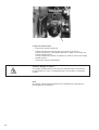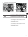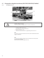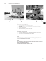
1
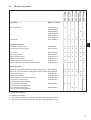
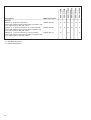
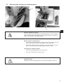
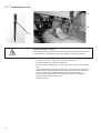
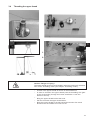
Manual, complete
580
Double-chainstitch buttonhole automat
Single-chainstitch automat for stitched eyelets
Operating Instructions
1
Installation Instructions
2
Service Instructions
3
Postfach 17 03 51, D-33703 Bielefeld • Potsdamer Straße 190, D-33719 Bielefeld
Telefon + 49 (0) 5 21 / 9 25-00 • Telefax + 49 (0) 5 21 / 9 25 24 35 • www.duerkopp-adler.com
Ausgabe / Edition: 09/2005
Printed in Federal Republic of Germany
Teile-Nr./Part.-No.: 0791 580001
580
Manual, complete
Contents
Operating Instructions
Installation Instructions
Service Instructions
Interconnection-diagram
9890 580001 B
All rights reserved.
Property of Dürkopp Adler AG and copyrighted. Reproduction or publication of the content in
any manner, even in extracts, without prior written permission of Dürkopp Adler AG, is
prohibited.
Copyright © Dürkopp Adler AG - 2005.
Foreword
This instruction manual is intended to help the user to become familiar
with the machine and take advantage of its application possibilities in
accordance with the recommendations.
The instruction manual contains important information on how to
operate the machine securely, properly and economically. Observation
of the instructions eliminates danger, reduces costs for repair and
down-times, and increases the reliability and life of the machine.
The instruction manual is intended to complement existing national
accident prevention and environment protection regulations.
The instruction manual must always be available at the machine/sewing
unit.
The instruction manual must be read and applied by any person that is
authorized to work on the machine/sewing unit. This means:
–
–
–
Operation, including equipping, troubleshooting during the work
cycle, removing of fabric waste,
Service (maintenance, inspection, repair) and/or
Transport.
The user also has to assure that only authorized personnel work on the
machine.
The user is obliged to check the machine at least once per shift for
apparent damages and to immediatly report any changes (including the
performance in service), which impair the safety.
The user company must ensure that the machine is only operated in
perfect working order.
Never remove or disable any safety devices.
If safety devices need to be removed for equipping, repairing or
maintaining, the safety devices must be remounted directly after
completion of the maintenance and repair work.
Unauthorized modification of the machine rules out liability of the
manufacturer for damage resulting from this.
Observe all safety and danger recommendations on the machine/unit!
The yellow-and-black striped surfaces designate permanend danger
areas, eg danger of squashing, cutting, shearing or collision.
Besides the recommendations in this instruction manual also observe
the general safety and accident prevention regulations!
General safety instructions
The non-observance of the following safety instructions can cause
bodily injuries or damages to the machine.
1. The machine must only be commissioned in full knowledge of the
instruction book and operated by persons with appropriate training.
2. Before putting into service also read the safety rules and
instructions of the motor supplier.
3. The machine must be used only for the purpose intended. Use of
the machine without the safety devices is not permitted. Observe all
the relevant safety regulations.
4. When gauge parts are exchanged (e.g. needle, presser foot, needle
plate, feed dog and bobbin) when threading, when the workplace is
left, and during service work, the machine must be disconnected
from the mains by switching off the master switch or disconnecting
the mains plug.
5. Daily servicing work must be carried out only by appropriately
trained persons.
6. Repairs, conversion and special maintenance work must only be
carried out by technicians or persons with appropriate training.
7. For service or repair work on pneumatic systems, disconnect the
machine from the compressed air supply system (max. 7-10 bar).
Before disconnecting, reduce the pressure of the maintenance unit.
Exceptions to this are only adjustments and functions checks made
by appropriately trained technicians.
8. Work on the electrical equipment must be carried out only by
electricians or appropriately trained persons.
9. Work on parts and systems under electric current is not permitted,
except as specified in regulations DIN VDE 0105.
10. Conversion or changes to the machine must be authorized by us
and made only in adherence to all safety regulations.
11. For repairs, only replacement parts approved by us must be used.
12. Commissioning of the sewing head is prohibited until such time as
the entire sewing unit is found to comply with EC directives.
13. The line cord should be equipped with a country-specific mains
plug. This work must be carried out by appropriately trained
technicians (see paragraph 8).
It is absolutely necessary to respect the safety
instructions marked by these signs.
Danger of bodily injuries !
Please note also the general safety instructions.
Index
Page:
Preface and general safety instructions
Part 1: Operating Instructions Cl. 580
1.
1.1
1.2
1.3
1.4
Product description
Designated use . . . . .
Brief description . . . . .
Subclasses . . . . . . . .
Structure of the product
2.
Technical data . . . . . . . . . . . . . . . . . . . . . . . . . . . . . . . . . . . . . . . . . . . . . . . . . 10
3.
3.1
3.2
3.3
3.4
3.5
3.6
Operation
Needles, threads and gimps . . . . . . . . . .
Removing and inserting the clamping plates
Changing the needle . . . . . . . . . . . . . .
Threading the upper thread . . . . . . . . . .
Threading the looper thread . . . . . . . . . .
Threading the gimp thread . . . . . . . . . .
4.
Swivelling the automat up and down . . . . . . . . . . . . . . . . . . . . . . . . . . . . . . . . . . 17
5.
5.1
Thread tension
Upper thread and looper thread tension . . . . . . . . . . . . . . . . . . . . . . . . . . . . . . . . . . 18
6.
Changing the cutting blocks and knives
6.1
6.1.1
6.1.2
Changing the cutting blocks and knives (580-312000 / 580-321000) “Multiflex” . . . . . . . . . . 22
Changing the knives. . . . . . . . . . . . . . . . . . . . . . . . . . . . . . . . . . . . . . . . . . . . . . 22
Changing the cutting blocks . . . . . . . . . . . . . . . . . . . . . . . . . . . . . . . . . . . . . . . . . 23
7.
Push buttons . . . . . . . . . . . . . . . . . . . . . . . . . . . . . . . . . . . . . . . . . . . . . . . . . 24
8.
Setting the fabric stops . . . . . . . . . . . . . . . . . . . . . . . . . . . . . . . . . . . . . . . . . . . 24
9.
9.1
9.2
9.3
Switching on - Switching off - Threading mode
Switching on . . . . . . . . . . . . . . . . . . . . . . . . . . . . . . . . . . . . . . . . . . . . . . . . . . 25
Switching off . . . . . . . . . . . . . . . . . . . . . . . . . . . . . . . . . . . . . . . . . . . . . . . . . . 25
Threading mode . . . . . . . . . . . . . . . . . . . . . . . . . . . . . . . . . . . . . . . . . . . . . . . . 25
10.
10.1
10.2
Control panel and control unit
General notes . . . . . . . . . . . . . . . . . . . . . . . . . . . . . . . . . . . . . . . . . . . . . . . . . 26
Control panel . . . . . . . . . . . . . . . . . . . . . . . . . . . . . . . . . . . . . . . . . . . . . . . . . 27
.
.
.
.
.
.
.
.
.
.
.
.
.
.
.
.
.
.
.
.
.
.
.
.
.
.
.
.
.
.
.
.
.
.
.
.
.
.
.
.
.
.
.
.
.
.
.
.
.
.
.
.
.
.
.
.
.
.
.
.
.
.
.
.
.
.
.
.
.
.
.
.
.
.
.
.
.
.
.
.
.
.
.
.
.
.
.
.
.
.
.
.
.
.
.
.
.
.
.
.
.
.
.
.
.
.
.
.
.
.
.
.
.
.
.
.
.
.
.
.
.
.
.
.
.
.
.
.
.
.
.
.
.
.
.
.
.
.
.
.
.
.
.
.
.
.
.
.
.
.
.
.
.
.
.
.
.
.
.
.
.
.
.
.
.
.
.
.
.
.
.
.
.
.
.
.
.
.
.
.
.
.
.
.
.
.
.
.
.
.
.
.
.
.
.
.
.
.
.
.
.
.
.
.
.
.
.
.
.
.
.
.
.
.
.
.
.
.
.
.
.
.
.
.
.
.
.
.
.
.
.
.
.
.
.
.
.
.
.
.
.
.
.
.
.
.
.
.
.
.
.
.
.
.
.
.
.
.
.
.
.
.
.
.
.
.
.
.
.
.
.
.
.
.
.
.
.
.
.
.
.
.
.
.
.
.
.
.
.
.
.
.
.
.
.
.
.
.
.
.
.
.
.
.
.
.
.
.
.
.
.
.
.
.
.
.
.
.
.
.
.
.
.
.
.
.
.
.
.
.
.
.
.
.
.
.
.
.
.
.
.
.
.
.
.
.
.
.
.
.
.
.
.
.
.
.
.
.
.
.
.
.
5
5
7
9
11
12
13
14
15
16
1
Index
Page:
10.3
10.4
10.4.1
10.4.1.1
10.4.2
10.4.2.1
10.4.2.2
10.4.3
10.4.4
10.4.5
10.4.6
10.4.7
10.5
10.5.1
10.5.2
10.5.3
10.5.4
10.6
10.6.1
10.6.2
10.6.3
10.6.4
10.6.5
10.6.6
10.7
Index of the control panel keys . . . . . . . . . .
Main level of menu system . . . . . . . . . . . . .
Altering the values of the main level directly . .
Selecting a buttonhole in the main level . . . .
Selecting a sequence or a buttonhole . . . . . .
Selecting a sequence (Sequence mode) . . . .
Selecting a buttonhole (Buttonhole mode) . . .
Adjusting the thread tension in the main level .
Adjusting the cutting length in the main level . .
Cutting mode . . . . . . . . . . . . . . . . . . . . .
The piece counter . . . . . . . . . . . . . . . . . .
Automatic or manual operation (can only be set
Buttonhole programming . . . . . . . . . . . . . .
Selection of a menu item . . . . . . . . . . . . . .
Editing of a value . . . . . . . . . . . . . . . . . .
Programming a buttonhole . . . . . . . . . . . .
List of menu and submenu items . . . . . . . . .
Sequences . . . . . . . . . . . . . . . . . . . . . .
General . . . . . . . . . . . . . . . . . . . . . . . .
Switching on / off the sequence mode . . . . . .
Programming a sequence . . . . . . . . . . . . .
Inserting a buttonhole at the end of a sequence
Deleting a buttonhole at the end of a sequence
Inserting a buttonhole in within a sequence . .
Sewing . . . . . . . . . . . . . . . . . . . . . . . .
. . . . . . . .
. . . . . . . .
. . . . . . . .
. . . . . . . .
. . . . . . . .
. . . . . . . .
. . . . . . . .
. . . . . . . .
. . . . . . . .
. . . . . . . .
. . . . . . . .
in sequence
. . . . . . . .
. . . . . . . .
. . . . . . . .
. . . . . . . .
. . . . . . . .
. . . . . . . .
. . . . . . . .
. . . . . . . .
. . . . . . . .
. . . . . . . .
. . . . . . . .
. . . . . . . .
. . . . . . . .
. . . . .
. . . . .
. . . . .
. . . . .
. . . . .
. . . . .
. . . . .
. . . . .
. . . . .
. . . . .
. . . . .
mode) .
. . . . .
. . . . .
. . . . .
. . . . .
. . . . .
. . . . .
. . . . .
. . . . .
. . . . .
. . . . .
. . . . .
. . . . .
. . . . .
.
.
.
.
.
.
.
.
.
.
.
.
.
.
.
.
.
.
.
.
.
.
.
.
.
.
.
.
.
.
.
.
.
.
.
.
.
.
.
.
.
.
.
.
.
.
.
.
.
.
.
.
.
.
.
.
.
.
.
.
.
.
.
.
.
.
.
.
.
.
.
.
.
.
.
.
.
.
.
.
.
.
.
.
.
.
.
.
.
.
.
.
.
.
.
.
.
.
.
.
.
.
.
.
.
.
.
.
.
.
.
.
.
.
.
.
.
.
.
.
.
.
.
.
.
.
.
.
.
.
.
.
.
.
.
.
.
.
.
.
.
.
.
.
.
.
.
.
.
.
.
.
.
.
.
.
.
.
.
.
.
.
.
.
.
.
.
.
.
.
.
.
.
.
.
.
.
.
.
.
.
.
.
.
.
.
.
.
.
.
.
.
.
.
.
.
.
.
.
.
.
.
.
.
.
.
.
.
.
.
.
.
.
.
.
.
.
.
.
.
.
.
.
.
.
.
.
.
.
.
.
.
.
.
.
.
.
.
.
.
.
.
.
.
.
.
.
.
.
.
.
.
.
.
.
.
.
.
.
.
.
.
.
.
.
.
.
.
.
.
.
.
.
.
.
.
.
.
.
.
.
.
.
.
.
.
.
.
.
.
.
.
.
.
.
.
.
.
.
.
.
.
.
.
.
.
.
.
.
.
.
.
.
.
.
.
.
.
.
.
.
.
.
.
.
.
.
.
.
.
.
.
.
.
.
.
.
.
.
.
.
.
.
.
.
.
.
.
.
.
.
.
.
.
.
.
.
.
.
.
.
.
.
.
.
.
.
.
.
.
.
.
.
.
.
.
.
.
.
.
.
.
.
.
.
.
.
.
.
.
.
.
.
.
.
.
.
.
.
.
28
29
29
30
32
32
32
33
33
34
34
35
36
36
36
37
38
41
41
41
42
43
43
44
45
11.
11.1
11.2
11.3
11.4
11.5
11.6
Information messages
Needle not in basic position
Threading mode . . . . . . .
Thread breakage . . . . . . .
Pressure monitor . . . . . .
Invalid cutting position . . .
Abnormal threading mode .
.
.
.
.
.
.
.
.
.
.
.
.
.
.
.
.
.
.
.
.
.
.
.
.
.
.
.
.
.
.
.
.
.
.
.
.
.
.
.
.
.
.
.
.
.
.
.
.
.
.
.
.
.
.
.
.
.
.
.
.
.
.
.
.
.
.
.
.
.
.
.
.
.
.
.
.
.
.
.
.
.
.
.
.
.
.
.
.
.
.
.
.
.
.
.
.
.
.
.
.
.
.
.
.
.
.
.
.
47
47
47
47
47
48
12.
Error messages . . . . . . . . . . . . . . . . . . . . . . . . . . . . . . . . . . . . . . . . . . . . . . . . 48
13.
13.1
13.2
13.3
Maintenance
Cleaning . . . . . . . . . . . . . . . . . . . . . . . . . . . . . . . . . . . . . . . . . . . . . . . . . . . . . 49
Lubricating . . . . . . . . . . . . . . . . . . . . . . . . . . . . . . . . . . . . . . . . . . . . . . . . . . . 50
Control . . . . . . . . . . . . . . . . . . . . . . . . . . . . . . . . . . . . . . . . . . . . . . . . . . . . . . 51
.
.
.
.
.
.
.
.
.
.
.
.
.
.
.
.
.
.
.
.
.
.
.
.
.
.
.
.
.
.
.
.
.
.
.
.
.
.
.
.
.
.
.
.
.
.
.
.
.
.
.
.
.
.
.
.
.
.
.
.
.
.
.
.
.
.
.
.
.
.
.
.
.
.
.
.
.
.
.
.
.
.
.
.
.
.
.
.
.
.
.
.
.
.
.
.
.
.
.
.
.
.
.
.
.
.
.
.
.
.
.
.
.
.
.
.
.
.
.
.
.
.
.
.
.
.
.
.
.
.
.
.
.
.
.
.
.
.
1.
Product description
1.1
Designated Use
The DÜRKOPP ADLER 580 is a sewing automat designed for the sewing
of buttonholes in light to medium-weight material.
Such material, which is generally made of textile or synthetic fibres, is
used in the clothing industry. Furthermore, this sewing automat can
possibly also sew so-called technical seams. However, in this case the
user has to evaluate the possible risks (preferably in cooperation with
DÜRKOPP ADLER) since such applications are rather rare and the
variety of possibilities is vast. According to the result of this evaluation
suitable safety measures are to be taken. Generally only dry fabrics must
be processed with this machine. The material must not be thicker than
8 mm when compressed by the lowered upper fabric clamps.
The material may not contain any hard objects. The person operating the
automat has to wear finger and eye protection. The sewing automat
must be installed and operated in dry and well-kept rooms only. If it is
operated in other rooms, that are not dry and well-kept further measures
which have to be agreed upon (see EN 60204-31:1999) can become
necessary. We as manufacturers of industrial sewing automats take it for
granted that at least semi-skilled operators are working with our products
so that we can assume that all usual operations and their risks are known
to them.
1.2
Brief description
The DÜRKOPP ADLER 580 is a double-chainstitch buttonhole
automat or a single-chainstitch automat for stitched eyelets with CNC
step motor technology for the material feed and the rotation of the
sewing mechanism.
The buttonhole automat works with two chainstitch loopers, the left one
being thread-guiding. For sewing of buttonholes with or without eye,
with taper tack, round tack, cross tack or without bartacks.
As eyelet automat it works with two chain stitch-blind-loopers for the
sewing of single stitched eyelets.
The automat is equipped with a upper thread trimmer and an
electronically regulated upper thread tension.
Depending on the subclass, the 580 comes with different types of
thread trimmer systems.
Technical features
The automat is driven by a positioning drive integrated in the machine
arm.
The drive for the motion of the axis X, Y and Z is effected by one step
motor for each axis. These drives are controlled via an electronic
control in conjunction with various pneumatic machine functions.
This drive and control system offers the following advantages:
– Variable sewing speed according to the sewing parameters
(e.g. upper thread, looper thread, material, seam width)
up to a maximum of 2200 stitches/min.
– Quiet running (no mechanical switching on and off).
Additional noise reduction by optimized needle bar and looper
drive.
– The use of step motors allows a very variable field of application.
No use of control cams.
– The control panel with membrane keyboard that is able to display
graphics is fitted on the right side of the sewing head within easy
reach of the operator.
5
1
–
–
–
–
–
–
–
–
–
–
–
The following functions are operated via manual switches:
- Closing and opening the clamp
- Activating the sewing operation
- Quick stop with needle position “up”
Pneumatic cutting of the buttonhole.
Automatic adaptation of the cutting power for the buttonhole knife
dependent on the programmed buttonhole length.
Due to the vertically working cutting system support no follow-up
work required in case of different cutting block heights.
Vacuum extraction of the eyelet cut wastes
Central oil wick lubrication from two oil reservoirs.
Switch at the head cover for moving to the ideal position for
threading in.
Electronically controlled upper thread tension.
In case of upper thread breakage the upper thread monitor
interrupts the sewing cycle, the fabric clamps remain closed and
hold the workpiece which can be removed at the touch of a button.
Covered, smooth design. The swivelling up of the automat is
supported by a gas-pressurized spring which also helps that the
machine head is swivelled back slowly.
The special design of the machine arm allows for a vertical
positioning of the fabric by using a different cloth detention device
(additional equipment).
Control
– Counter indicating the number of buttonholes sewn on the display.
– You can define up to 50 different buttonholes. Up to 25 buttonhole
sequences with up to 5 programmed buttonholes can be
memorized. One sequence may contain up to 9 different
buttonholes, every buttonhole can be 9 times repeated
consecutively within the sequence.
– Integrated test and monitoring system ”Multitest”. This system
allows not only for a monitoring of the sewing process but also for
a quick testing of the input and output elements as well as of the
motor functions without additional measuring instruments.
– By means of a setting provision on the display it is made possible
that the fabric support plate moves to the initial position of the next
buttonhole after releasing the workpiece. This allows for a better
view when positioning the fabric.
– According to the buttonhole type the following parameters can be
set at the control:
- with or without eye
- tack type
(with taper tack, round tack, cross tack or no tack)
- max. speed: 2200 min -1
- buttonhole length
- cutting before or after sewing
- no cutting
- stitch distance
- form of eye
- electronic setting of the stitch row gauge (+/- 0,5 mm)
- number of stitches in the eye
6
1.3
Subclasses
580-112000
With short trimmer for the upper and the looper thread.
The looper thread trimmer is integrated into the throat
plate so that the tread can be trimmed very close to the
fabric. To be used for buttonholes with taper tack, cross
tack, with or without eye.
In conjunction with the corresponding sewing
equipment, it can be also be used for double-stitched
eyelets.
An electropneumatic upper thread catcher is part of the
standard equipment.
The cut length is max. 38 mm, depending on the sewing
equipment.
Without a lower gimp.
580-121000
With short trimmer for the upper thread and long thread
trimmer (approx. 30 mm thread length) for the looper
thread and the gimp.
Looper thread and gimp can thus be pulled tight or
pulled through for the subsequent sewing of a lockstitch
tack.
After the sewing of a cross tack they are trimmed short
manually.
To be used for buttonholes with or without eye, for
cutting before or after sewing, with taper, round and
cross tacks or no tacks.
For cut lenghts of up to 38 mm.
An electropneumatic thread catcher and a lower gimp
guide are part of the standard equipment. It catches the
upper thread right after the trimming, holds it and lays it
when sewing the next buttonhole into the right
buttonhole seam. This guarantees:
- a safe seam beginning also with light and loose fabric .
- tightly pulled stitches from beginning of sewing.
- a proper buttonhole rearside, no more cleaning out.
580-141000
With short trimmer for upper and looper thread and lower
gimp.
To be used for buttonholes with or without eye, for cutting
before or after sewing, with taper, round and cross tacks or
no tack.
With these automats buttonhole length, cutting length and
taper tack length can be adjusted after insertion of
corresponding clamping plates.
Three set of clamping plates are designated:
L1 for sewing lengths of 12 - 24 mm
L2 for sewing lengths of 16 - 28 mm
L3 for sewing lengths of 24 - 36 mm
Different taper tack lengths are possible within these
groups.
An electropneumatic thread catcher and a lower gimp
guide are part of the standard equipment.
580-151000
With short trimmer for the upper thread.
Universal machine for cut lenghts of 10 - 50 mm and
buttonholes in fabric of different qualities and thickness,
depending on the sewing equipment optional with or
without lower gimp.
In conjunction with the corresponding sewing equipment
also to be used for single-chain stitch eyelets.
To be used for buttonholes with or without eye, for
cutting before or after sewing, with taper, round and
cross tacks or no tack.
7
1
8
580-312000
With short trimmer for upper and looper thread.
The looper thread trimmer is integrated into the throat
plate, so that the thread can be trimmed very close to
the fabric.
Equipped as standard with an electropneumatic upper
thread catcher and the buttonhole cutting system
“Multiflex”. The “Multiflex” system allows the cutting of
various buttonhole length, buttonhole shapes and round
eyelets without changing the cutting tools.
Equipped as standard with two cutting blocks and three
knives.
Cutting length from 16 mm up to 36 mm or from 9 mm
up to 31 mm can be set, depending on the cutting block.
Special cuttings like only the buttonhole eye, buttonhole
seam are possible with the standard equipment.
Without a lower gimp.
580-321000
With short trimmer for the upper thread and long thread
trimmer for the looper thread and the gimp.
Looper thread and gimp can thus be pulled tight or
pulled through for the subsequent sewing of a lockstitch
tack. After the sewing of a cross tack they are trimmed
short manually.
Equipped as standard with an electropneumatic upper
thread catcher and the buttonhole cutting system
“Multiflex”. The “Multiflex” system allows the cutting of
various buttonhole length, buttonhole shapes and round
eyelets without changing the cutting tools.
Equipped as standard with two cutting blocks and three
knives.
Cutting length from 16 mm up to 36 mm or from 9 mm
up to 31 mm can be set, depending on the cutting block.
Special cuttings like only the buttonhole eye, buttonhole
seam are possible with the standard equipment.
With a lower gimp guide and a gimp advancing device.
1.4
Structure of product
Equipment
Material number
Sewing automat
990001
990002
990004
990005
990021
990022
580501
X
Accessories
0580
0580
0580
0580
0580
0580
0791
X
X
Optional equipment:
Pneumatic connection set
Integral sewing lamp (LED)
0797 003031
0580 100344
O
X
Foot switch
Upper gimp guide
Upper thread catcher
Upper thread catcher
Fabric deflector for back trousers
Support table for operating while standing
9880
0580
0580
0580
0580
0580
580-151000
580-141000
580-321000
580-121000
580-312000
580-112000
Subclasses
X
X
X
X
X
X
X
X
X
O
X
O
X
O
X
O
X
O
X
O
O
O
O
O
O
O
X
X
X
X
X
1
580002
590804
590154
590144
590574
590504
O
O
O
O
O
O
O
O
Positioning aids
Spacer for the distance buttonhole to buttonhole (R+L) 0580 590294
Spacer (R+L) for the distance buttonhole to fabric edge 0580 590404
O
X
O
X
O
X
O
X
X
O
X
O
O
Ñ
O
O
O
Center stop guide
Laser marking lamp
Slide-on table for vertical positioning
Kit for vertical positioning
(left and right clamping plate)
Kit for vertical positioning
(left and right clamping plate)
Kit for vertical positioning
(left and right clamping plate)
O
591224
590564
590604
590554
D
O
O
0580 590384
O
O
0580
0580
0580
0580
0580 590374
O
O
O
X = Standard equipment
O = Optional equipment
D = Can only be ordered in connection with the sewing equipment E1151
Ñ = Can only be ordered in connection with the length package L1 or L2
9
10
580-121000
580-321000
580-141000
580-151000
O
O
O
O
O
O
O
O
O
O
O
O
Material number
Stands
MG58-13 (regular installation)
MG58 400104
Stand with fastening parts and table top 1060 x 750
incl. maintenance unit and rollers
MG58-13 (regular installation of a narrow stand)
MG58 400124
Stand with fastening parts and table top 620 x 750
incl. maintenance unit and rollers
MG58-13 (vertical positioning, narrow stand)
MG58 400114
Stand with fastening parts and table top 1060 x 600
incl. maintenance unit and rollers
X = Standard equipment
O = Optional equipment
580-312000
Equipment
580-112000
Subclasses
O
O
O
2.
Technical data
Machine head:
Class 580
Type of sewing stitch:
Double-chain stitch
Number of needles:
1
Needle system:
558 / 579
Attention!
When changing over from one needle system to the other the distance
between looper and needle and the adjustment of the needle
protection have to be checked imperatively (see service instructions).
Max. needle size:
Nm 80-120 (558) / Nm 90-125 (579)
Upper thread size:
max. Nm 50
Looper thread size:
max. Nm 30
Max. speed:
2200 min
Stitch length:
0,5 - 2 mm
Max. sewing length:
(depend. on sewing equip.)
38
38
38
50
38
38
mm
mm
mm
mm
mm
mm
(subclass
(subclass
(subclass
(subclass
(subclass
(subclass
580-11200)
580-12100)
580-14100)
580-15100)
580-31200)
580-32100)
Max. cutting length:
(depend. on sewing equip.)
38
38
32
50
36
36
mm
mm
mm
mm
mm
mm
(subclass
(subclass
(subclass
(subclass
(subclass
(subclass
580-11200)
580-12100)
580-14100)
580-15100)
580-31200)
580-32100)
Operating pressure:
6 bar ± 0,5 bar
Air consumption:
approx. 3 NL per working cycle
Rated load:
320 VA
Rated voltage:
1 x 190-240 V, 50/60 Hz
Dimensions
Machine head:
550 x 370 x 580 (L x W x H)
Table top (regular installation):
1060 x 750 x 1150 mm (L x W x H)
Table top (narrow stand):
620 x 850 x 1150 mm (L x W x H)
Working height:
730-900 mm
(upper edge of the table top)
upper edge of the machine table:
830-1000 mm
Weight with stand:
approx. 160 kg
Weight of head:
approx. 100 kg
Weight of control:
approx. 12 kg
-1
1
11
3.
Operation
3.1
Needles, threads and gimps
Needles
Needle system: 558 / 579
Needle sizes:
Nm 80-120 (558) / Nm 90-125 (579)
according to the type of sewing thread, fabric and
sewing equipment (E-No.).
Attention!
When changing over from one needle system to the other the distance
between looper and needle and the adjustment of the needle
protection have to be checked imperatively (see service instructions).
Threads
The look of the buttonhole is essentially influenced by the sewing
thread used.
Threads of synthetic fibre or silk threads can be used as needle and
looper threads.
The look of the buttonhole is essentially influenced by
– the thread used.
– the use of different upper and looper thread sizes.
Gimps
The gimp is meant to stabilize the buttonhole and to give it a relief-type
appearance at the same time.
It should have the following features:
– not too thick, but supple and tight
– even thickness
The threads mentioned in the following table are recommendations
only. Depending on the sewing equipment (E-No.) and the material
also other threads and thread sizes may be required.
Subclass
Type and size of upper
thread
Type and size of looper
thread
Type and size of lower
gimp
580-112000
Polyester fibre thread,
schappe-silk spun
70/3
80/3
Polyester fibre thread,
schappe-silk spun
70/3
70/3
not necessary
Poly-Poly 80/2
Poly-Poly 80/2
Poly-Schappe 15/3
580-312000
580-141000
580-151000
580-321000
12
3.2
Removing and inserting the clamping plates
1
3
1
Caution: Danger of injury !
The removing and inserting of the clamping plates 1 has to be done
with the sewing automat switched off or in the position “Threading
mode” (see chapter “Threading mode”).
Removing the clamping plate
– Lift the right clamping plate 1 slightly at the rear and pull it to the
back. Then remove the clamping plate to the right side.
– Lift the left clamping plate 1 slightly at the rear and pull it to the
back. Then remove the clamping plate to the left side.
Inserting the clamping plates
– Push the clamping plate into its front seat.
– Then snap it at the rear into the pin 3.
Important note!
Wrongly inserted clamping plates can lead to damage or injuries
13
3.3
Changing the needle
1
2
3
Caution: Danger of injury !
The needle has to be changed with the sewing automat switched off or
in the position “Threading mode” (see chapter “Threading mode”).
–
–
–
–
–
14
Loosen the screw 1 (Allen key in the accessories).
Pull the needle 2 out of the needle bar.
Push the new needle as far as it will go into the hole of the needle
bar.
Align the needle 2 so that the hollow groove points to the front and
the flat side 3 at the needle butt to the left (towards the fastening
screw 1). Only the needle system 579 has this flat side 3 !
When using needle system 558 align the needle 2 so that the
hollow groove points to the front.
Tighten screw 1.
3.4
Threading the upper thread
1
1
2
Caution: Danger of injury !
The upper thread must only be threaded in when the machine is switched
off or in the “Threading mode” (see chapter “Threading mode”).
–
–
–
–
–
Thread in the upper thread as shown in the illustrations.
In order to thread in the upper thread push the threading wire (part
of the accessories) through the hollow needle bar 1 from the
bottom to the top.
Bring the upper thread behind the hook.
Pull the wire with the upper thread down.
Bring the upper thread to the left behind the tension disc 2 and
thread it into the needle from rear to front.
15
3.5
Threading the looper thread
looper thread
gimp thread
Caution: Danger of injury !
The looper thread must only be threaded in when the machine is switched off
or in the “Threading mode” (see chapter “Threading mode”).
The automat must be in its final position, i.e. the looper turret with the
loopers has to point to the front.
– Remove the clamping plates (see chapter 3.2).
– Swivel the automat upwards.
– Thread in the looper thread according to the illustrations with the
help of the long threading wire included in the accessories.
– Leave an approx. 25 mm long looper thread end hang out of the
stitch hole of the throat plate.
– Insert the clamping plates (see chapter 3.2).
16
3.6
Threading the gimp thread
looper thread
gimp thread
Caution: Danger of injury !
The gimp thread must only be threaded in when the sewing machine is
switched off or in the “Threading mode” (see chapter “Threading mode”).
–
–
–
Thread in the gimp thread as shown in the illustrations, depending
on the subclass.
With the Subclass -141000: thread in the gimp as shown in
illustration A.
Leave a gimp end approx. 25 mm long hang out of the gimp hole of
the stitch plate.
Sew a buttonhole and check whether the gimp is pulled back
sufficiently.
With the Subclass -151000: thread in the gimp as shown in
illustration B.
A
B
Only for the subclass 580-141000
17
1
4.
Swivelling the automat up and down
Caution: Danger of injury !
The automat must only be swivelled up when the machine is
switched off or in the “Threading mode” (see chapter “Threading
mode”).
1
For various operations (e.g. for threading the looper thread or the gimp
thread) the automat has to be swivelled up.
Swivelling up:
– Pull the locking bolt 1 and lift the automat at the front.
– Let the locking bolt 1 go again and let it click into one of the
drill-holes (maybe you have to move the automat up and down a
little).
– You should not let the automat go before the locking bolt 1 has
snapped in.
Swivelling down:
– Keep hold of the automat and pull the locking bolt 1.
– Swivel the automat down slowly.
Important !
When the automat is swivelled up very high, the effect of the
gas-pressurized spring that is to slow down the downward
movement is rather low at first. Therefore keep hold of the automat
when you swivel it down.
Operating the automat when it is swivelled up can lead to injuries and
damage.
18
5.
Thread tension
5.1
Upper thread and looper thread tension
1
1
The thread tensions are dependent on the type and quality of the
threads and fabrics. The buttonhole looks best if it is sewn with the
lowest possible thread tension.
Too tight thread tensions can lead to undesired ruffling and thread
breakage, particularly when processing thin materials.
Upper thread tension
In general the upper thread tension has to be tighter than the looper
thread tension. The upper thread tension is designed as an electronic
tension. It consists of the main tension for the sewing process and a
remaining tension (cutting tension) for tightening the upper thread
during the cutting operation under the throat plate.
Depending on the elasticity of the upper thread used, the remaining
tension (cutting tension) has to be adjusted in such a way that the
upper thread end hanging out of the needle is long enough to ensure a
safe sewing start.
– Adjust the main tension for the sewing operation via the control
panel (see chapter 9.3.2 Adjusting the thread tension in the main
level).
– Adjust the remaining tension (cutting tension) via the control panel
(menu item 130).
19
1
Looper thread tension
– Swivel the machine head up.
– Adjust the looper thread tension by means of tensioner 1.
Turn the tensioner in clockwise direction in order to increase the
looper thread tension.
Turn the tensioner counter-clockwise in order to reduce the looper
thread tension.
– Swivel the machine head down.
Caution: Danger of injury !
The looper thread tension must only be adjusted when the machine
is switched off or in the “Threading mode” (see chapter “Threading
mode”).
Hint
The length of the starting thread can be adjusted by changing the
thread tension at the start.
20
6.
Changing of cutting blocks and knives
1
2
4
3
1
The cutting length can be altered by changing the cutting blocks.
Caution: Danger of injury !
Change the cutting block or the knife only when the buttonhole
automat is switched off!
Change the cutting block
– Loosen the Allen screw 1 (Allen key is part of the accessories).
– Pull the cutting block 2 to the front and remove it.
– Insert new cutting block and push it as far as it will go.
– Tighten the Allen screw 1 again.
Change the knife
– Loosen the Allen screw 3 (Allen key is part of the accessories).
– Pull the knife 4 to the front and remove it.
– Insert new knife and push it as far as it will go.
– Tighten the Allen screw 3 again.
21
6.1
6.1.1
Changing the cutting blocks and knives (580-312000 / 580-321000) “Multiflex”
Changing the knives
3
1
4
2
Caution: danger of injury
Knives may only be changed with the machine switched off .
–
–
–
Loosen the Allen screw 2 or 4.
(The Allen key is in the accessories).
Remove the knife 1 or 3.
Insert the new knife and fix it by tightening the screw 2 or 4.
Hint
If the knife cannot be removed, the screw of the second knife must be
slightly unfastened.
Hint
If a knife with a different shape has to be inserted, the control panel
has to be set accordingly.
(See service instructions chapter 29.4.8)
22
6.1.2
Changing the cutting blocks
2
1
4
3
1
Removing the cutting-block
– Disconnect the compressed-air supply
– Use a screwdriver 2 to push gently the cutting-block holder 1
downward.
– Loosen the screw 3.
– Pull out the cutting-block 4 to the left.
Fitting the cutting-block
– Insert the cutting-block 4 in the guide and tighten the screw 3.
– Connect the compressed-air supply again.
Hint
The cutting-block 1 will then move automatically upward, after the
compressed-air hose is connected.
Hint
If a cutting block with a different length has to be inserted, the control
panel has to be set accordingly.
(See service instructions chapter 29.4.8)
23
7.
Push buttons
By means of the push buttons it is possible to control the clamps and to
start the sewing operation. According to the setting in the service menu
(see service instructions) the function is different.
1. Setting
– Key 1: The clamps are opened or closed respectively.
– Key 2: The sewing operation starts when the clamps are closed.
2. Setting
– Key 1: The clamps are opened or closed respectively.
– Key 2: If the clamps are not lowered, they will be lowered now. The
sewing operation starts.
8.
Setting the fabric stops
Caution: Danger of injury !
Adjust the fabric stops only when the buttonhole automat
is switched off!
2
1
1
–
–
–
–
24
Place the sewing material until it touches the fabric stops 2 on both
sides (right and left).
Loosen the screws 1 on the right and left.
Adjust the sewing position by moving the fabric stops 2.
Tighten the screws 1 again.
9.
Switching on - Switching off - Threading mode
9.1
Switching on
1
–
Switch on the main switch 1.
The machine moves to the loading position and is ready for sewing.
1
9.2
Switching off
–
Switch off the main switch 1.
All drives and the control are immediately cut off the electric supply
lines.
Attention!
The main switch is also the emergency stop button! When the main
switch is turned off, the machine is separated from the power supply!
9.3
Threading mode
Attention!
The “Threading mode” must only be used for the operations necessary
for threading the upper thread, the looper thread and the gimp thread!
For all further operations (e.g. change of knife or cutting block) the
machine has to be switched off with the main switch!
Switching on the “Threading mode”
– Press key 2 in the front plate. The key must engage!
The sewing automat is in the ”Threading mode".
In the “Threading mode” the key is illuminated.
The cloth carrier plate moves to the position best for threading.
The cloth clamps remain in the same position as they were when
switching on the “Threading mode”.
The sewing drive is separated from the power supply.
The knife for cutting open is switched off.
Switching off the “Threading mode”
– Press key 2 again. The key must be released.
After a short stop the sewing automat is ready for sewing again. The
sewing operation is continued where the ”Threading mode" had been
activated.
2
25
10.
Control panel and control
10.1 General notes
The buttonhole automat of the class 580 is equipped with a
programmable control.
Up to 50 different buttonholes can be defined.
The buttonholes can be memorized in up to 25 sequences.
One sequence can consist of up to 9 different buttonhole, each single
buttonhole can be repeated within one sequence up to 9 times
successively.
When sewing the operator has the option to change automatically or
manually between the programmed buttonholes.
Among the following buttonhole types can be chosen:
– Buttonholes with taper tack
– Buttonholes with round tack
– Buttonholes with cross tack
– Buttonholes without tack
– Stitched eyelets
For all types of buttonholes the relevant characteristics of the
buttonhole e. g. buttonhole length and eye shape can be programmed
(see the chapter “Buttonhole programming”).
Attention!
Not all the different buttonhole types can be accomplished with each
subclass and sewing equipment.
26
10.2 Control panel
You can programme the control using the control panel and also set
the fucntion of each buttonhole.
This can be done through actuating directly the corresponding key or
by altering some parameters.
Entering the parameters should be done in the programming mode “P”.
The parameters and the allocated values will be shown at the display.
To avoid an accidental altering of the pre-set values, the operating of
the control panel is splitted in different levels (Operator, Technician,
Manufacturer).
The operator (seamstress) can directly access his/her level.
Accessing the other levels are possible through entering a code
number.
1
27
10.3 Index of the control panel keys
Key on control panel
Designation of key in this manual
“ESC”- key
“P”- key
“F”- key
“S”- key
“OK”- key
key ï
key ð
key ñ
key ò
28
10.4 Main level of the menu system
After switching on the automat and during sewing the display shows
the main level of the menu system.
In the main level the following values are displayed:
- Sequence number
Sequence mode
- Buttonhole sequence
or
- Buttonhole number
Single buttonhole mode
- Empty line
Sequence mode
and
– Upper thread tension
– Cut length
– Cut mode
(Depending on the sewing equipment the buttonhole can be cut
open before or after sewing or not cut open at all).
– Daily pieces counter
1
Single buttonhole mode
The following options are available in the main level:
- Direct editing of values in the main level
- Programming of buttonholes (”P”-key)
- Programming of buttonhole sequences (”S”-key)
- Service menu (”F”-key)
10.4.1
Altering the values of the main level directly
The values of the main level can directly be altered as follows:
keys ñò
Select the line that you want to alter with the ñò keys.
“OK”-key
Press the “OK”-key.
The cursor will blink in the selected line.
Select the digit that is to be altered with the ïð keys.
Alter the selected value with the keys ñò. With the key
ñ you increase the value, with the key ò you reduce it.
keys ïð
keys ñò
“OK”-key
Confirm the set value with the “OK”-key.
If you do not want to confirm the set value, press the
“ESC” key.
The previous value will be reestablished.
29
10.4.1.1
Selecting a buttonhole in the main level
Sequence mode
In the main level it is possible to change any time between the
memorized buttonholes of the sequence.
1
2
Keys ïð
With the ïð keys it is possible to select any buttonhole
of the displayed sequence.
The selected buttonhole will be highlighted with a bar.
To help you, the present buttonhole contour will be
displayed in the field 1 and in the field 2 the
corresponding values.
3
Monoflex mode
Two knife positions are possible with the subclasses
580-312000 and 580-321000 that is why the field 3
shows a bar in addition.
The bar position shows which knife position is allocated
to the buttonhole.
30
Single buttonhole mode
In the main level you can select a previously memorized buttonhole.
1
2
Keys ñò
Select the first line with the ñò keys. The selection of
buttonholes is only possible in line 1.
“OK”-key
Press the “OK”-key.
The cursor will blink.
Select the desired buttonhole number with the ñò keys.
To help you, the present buttonhole contour will be
displayed in the field 1 and in the field 2 the
corresponding values.
keys ñò
3
Monoflex mode
Two knife positions are possible with the subclasses
580-312000 and 580-321000 that is why the field 3
shows a bar in addition.
The bar position shows which knife position is allocated
to the buttonhole.
“OK”-key
Press the “OK”-key to confirm.
31
1
10.4.2
Selecting a sequence or a single buttonhole
Depending on the setting in the sequence menu either the sequence
mode or the single buttonhole mode is available
(see “Sequence programming”)
10.4.2.1
Selection of a sequence (Sequence mode)
After switching on the top line of the display appears white on black.
The sequence last sewn is displayed.
keys ñò
Skip with the ñò keys to the field “sequence number”.
“OK”-key
10.4.2.2
keys ñò
Press the “OK”-key.
The cursor blinks in the selected line.
Set the desired sequence with the ñò keys.
“OK”-key
Confirm the desired sequence by pressing the “OK”-key.
Selection of a buttonhole (single buttonhole mode)
If the sequence number appears in the top line after switching on
(e.g. “3”), the single buttonhole mode is activated in the sequence
menu.
In this mode no sequences can be activated anymore.
The last sewn buttonhole is displayed.
32
10.4.3
Adjusting the thread tension in the main level
The display indicates in field 2 the upper thread tension during the
sewing process. The tension can be adjusted in the main level.
2
Keys ñò
Skip with the ñò keys to field 2 “upper thread tension”.
“OK”-key
Keys ñò
Press the “OK”-key.
The cursor blinks.
Set the desired value with the òñ keys.
“OK”-key
Confirm by pressing the “OK”-key.
1
10.4.4
Adjusting the cut length in the main level
The display indicates in field 3 the cut length. The cut length can be
adjusted in the main levels.
3
Keys ñò
Skip with the ñò keys to field 3 “cut length”.
“OK”-key
Keys ñò
Press the “OK”-key.
The cursor blinks.
Set the desired value with the òñ keys.
“OK”-key
Confirm by pressing the “OK”-key.
33
10.4.5
The cutting mode
1
In the cutting mode, it is possible to switch between the following
parameters:
0 = no cut
CA = cut after sewing
CB = cut before sewing
10.4.6
Keys ñò
Skip with the ñò keys to field 1 “cutting mode”.
“OK”-key
Keys ñò
Press the “OK”-key.
The cursor blinks.
Set the desired value with the òñ keys.
“OK”-key
Confirm by pressing the “OK”-key.
The piece counter
The buttonhole automat 580 is equipped with a piece counter that
counts the number of buttonholes sewn.
After the “å“ sign the current figure is indicated.
The value of the piece counter is memorized also when the automat is
switched off.
The piece counter can count up to 9999 buttonholes. When this figure
is reached the counter restarts at 0.
2
Resetting the piece counter:
keys ñò
Skip with the ñò keys to field 2
“piece counter”.
34
“OK”-key
Press the “OK”-key.
The piece counter blinks.
“OK”-key
Press the “OK”-key for approx. 1.5 second.
The piece counter is set to 0 and the display changes
back to the main level.
10.4.7
Automatic or manual operation (only adjustable in the sequence mode)
The buttonhole automat functions in manual or automatic operation
mode depending on the setting.
Automatic operation
In the sequence indicated on the display, arrows are indicated between
the types of buttonhole programs.
After sewing one buttonhole the control automatically switches to the
next type of buttonhole. After sewing the last buttonhole, the control
switches to the first buttonhole within the sequence.
The current buttonhole is highlighted with a bar.
The type of the buttonhole being currently sewn is indicated in the left
half of the display.
Manual operation
In the sequence indicated on the display, instead of arrows, there are
hyphens between the types of buttonholes.
The control does not switch automatically from one type of buttonhole
to the other.
The current buttonhole is highlighted with a bar.
The type of the buttonhole being currently sewn is indicated in the left
half of the display.
Light barrier mode
If the kit “light barrier 0580 591524” is mounted, it is possible to
operate the machine in light barrier mode.
Two light barriers recognize automatically whether it is a lapel or a
jacket front edge and will call automatically the appropriate program.
Two programs must be listed in the sequence. The light barrier mode is
indicated by the symbol 1.
1
Switching between automatic, manual and light barrier operation
keys ñò
Select with the ñ and ò arrow keys the line that
indicated the current sequence.
“OK”-key
keys ñò
Press the “OK”-key.
Switch with the ñ and ò arrow keys between the two
operation modes.
The arrows between the buttonhole types appear or
disappear respectively.
“OK”-key
or
Press the “OK”-key to confirm the selection
“ESC”-key
Press the “ESC”-key to abort or cancel the selection.
Selecting the buttonhole to be sewn next in a sequence
When the sewing menu is visible on the display it is at any time
possible to switch from one memorized buttonhole to another.
Press the ïð keys or one of the arrow keys ï or ð.
Within the displayed sequence the next or
respectively the precedent buttonhole type
will be selected.
35
1
10.5 Buttonhole programming
The menu system 580 is divided into several levels.
In the main level the most important information for the sewing
operation are indicated.
From this main level it is possible to switch to the programming level in
order to program buttonholes.
A menu item can include further submenu items.
10.5.1
Selection of the programming level
“P”-key
Key ñò
“OK”-key
“ç”-key
10.5.2
Press the “OK”-key in order to alter the value of the
selected menu item.
If the selected menu item includes submenus, after
pressing the “OK”-key a menu item of the selected
submenu will be displayed. Skip in the same way with
the ñò keys to the desired submenu item and confirm
your selection by pressing the “OK”-key. Now you can
alter the value.
By pressing the “ç”-key you will get back to the
previous level.
“ESC”-key
By pressing the “ESC”-key you will always get directly
back to the main level.
Keys ïð
With the keys ïð you select the digit of the value you
want to alter.
The values can only be altered in certain steps. The
sewing speed for example can only be altered in steps
of 1000 or 100, i.e. the digits 10 and 1 cannot be selected.
With the key ñ the value of the selected digit is
increased.
With the key ò the value of the selected digit is
reduced.
All values have a defined minimum and maximum
that cannot be exceeded.
Altering a value
Keys ñò
36
Press the “P”-key in order to switch from the main level
to the menu for programming buttonholes. A menu item
will be displayed.
If the menu item has no submenus you will see a value
on the display that you can alter.
If the menu item does include submenus you will see
four dots on the display. The values to this menu item
are to be set in the submenus.
Skip with the ñò keys to the desired menu item.
“OK”-key
With the “OK”-key you confirm the altered values.
You return to the menu selection.
“ESC”-key
With the “ESC”-key you abort the value alteration.
The previous value is reestablished. You return to
the menu selection.
10.5.3
Programming of a buttonhole
“P”-key
Keys ñò
Press the “P”-key in order to switch from the main level
to the menu for programming buttonholes.
Select with the ñò keys the menu item “buttonhole
number.”
“OK”-key
Keys ñò
Press the “OK”-key to activate the menu item.
Select with the ñò keys the buttonhole that you want to
alter.
“OK”-key
Keys ñò
Press the “OK”-key.
Select with the ñò keys the menu item “tack type”.
“OK”-key
Keys ñò
Press the “OK”-key to activate the menu item.
Select with the ñò keys the tack type of the selected
buttonhole.
“OK”-key
Press the “OK”-key.
1
Important note!
When altering the tack type of a buttonhole program, all other values
of the buttonhole are reset to the standard value!.
Thus always select the tack type first, before you set all the
other values of a buttonhole!
–
Now adjust all the other parameters according to your needs.
37
10.5.4
List of menu and submenu items
Menu item
Description
Buttonhole number: up to 5 different buttonholes can be programmed.
Taper tack selection: buttonholes with taper tack (1), cross tack (2), round tack (3), and
without tack (0) can be programmed.
Length adjustments
Sewing length: the sewing length can be set from 6 to 42 mm, depending on the
equipment.
Eyelet diameter*: the internal diameter of the eyelet can be set from 2 to 7 mm, depending
on the equipment.
Stitch length in the lip: the distance from stitch to stitch within the lip (from 0,5 to 2 mm).
Number of stitches in the eyelet*: the number of the stitches that are evenly distributed
over the entire eyelet.
Eyelet overlap*: the overlapping of the seam beginning and the seam end.
Thread trimming length: with the Subclass 580-112000 / 0580-312000, it is possible to
alter the length of the needle thread on the underside of the buttonhole .
Length of the condensed stitches at the seam beginning: the distance from stitch to
stitch within the stitch condensation at the seam beginning.
Length of the condensed stitches at the seam end: the distance from stitch to stitch
within the stitch condensation at the seam end.
Number of condensed stitches at the seam beginning: the number of stitches within the
stitch condensation at the seam beginning.
Number of condensed stitches at the seam end: the number of stitches within the stitch
condensation at the seam end.
Upper thread tension
Sewing tension: the sewing tension regulated electronically during the sewing cycle.
Trimming tension: remaining upper thread tension for the upper thread trimmer .
Tension at the sewing start: upper thread tension at the seam beginning.
38
Menu item
Description
Eye settings
Eye type: up to 6 different eye types can be programmed.
Knife Shape
No.
0
1
2
3
4
5
(X x Y)
0,0x0,0
1,3x3,0
2,1x3,2
2,8x4,3
3,0x4,6
3,2x5,4
Buttonhole shape for
cutting after sewing/
no cutting
(X x Y)
0,0x0,0
1,6x3,5
2,4x3,9
3,3x4,6
3,6x4,8
3,6x6,1
Buttonhole shape for
cutting before sewing
(X x Y)
0,0x0,0
1,1x2,6
1,7x2,8
2,4x3,9
2,6x4,1
2,8x4,7
1
Number of stitches in the eye: the number of stitches to be set for the circle of the
buttonhole eye is min 4 to max 25 stitches.
Eye inclination: the buttonhole eye can be slightly inclined to the left or to the right.
Throw width: the mechanically regulated throw width (stitch width) can be enlarged or
reduced up to 0.5 mm.
Cut settings
Cutting mode: depending on the sewing equipment, the buttonhole can be cut after sewing
(1), before (2), or not cut at all.
0 = no cutting
CA = cutting after sewing
CB = cutting before sewing
Cutting area: the inner distance between the lips of the buttonhole is called cutting area.
Modus Multiflex 580-312000/ 580-321000
Cutting area: 1 = complete cut, 2 = medium cut, 3 = eye cut
Cutting length with complete cut : it is only possible to reduce the cutting length
about 2 mm.
Cutting position with medium cut: the position is changeable and can be given as
percentage, it rises from the eye (0%) to the rearmost (100%) position.
Cut correction in x-direction: the knife’s position can be moved to the right or to the left
within the buttonhole.
Cut correction in y-direction: the knife’s position can be moved to the front or to the rear
within the buttonhole.
Correction of cutting pressure: automatic adjustment (4 steps) of the cutting force of the
buttonhole knife depending on the buttonhole length.
-buttonhole length (eyelets) up to 14 mm
2 steps
-buttonhole length from 15 mm to 30 mm
3 steps
-buttonhole length from 31 mm
4 steps
In this menu item the preset cutting force can be increased or decreased, depending on the
buttonhole length.
39
Menu item
Description
Flexible cutting: Monoflex mode 580-312000 / 580-321000
Taper tack settings
Taper tack length: the taper tack length can be set from 2 mm to 36 mm, depending on the
sewing equipment and the buttonhole length.
Throw width in the taper bar: the mechanically regulated throw width (stitch width) can be
reduced. Attention! The reduction depends on the setting of the throw width in the menu item
150.
Overlapping in the taper bar: overlapping of the buttonhole seams in the taper tack.
Height of the taper slant: the length of the taper in the tack can be set.
Cross tack settings
Cross tack length: the overall length of the cross tack.
Stitch length in the cross tack: distance from stitch to stitch within the cross tack (from
0,5 mm to 2 mm).
Throw width in the cross tack: the mechanically regulated throw width (stitch width) can
be enlarged or reduced.
x-position of the cross tack: the whole cross tack can be shifted to the right/left.
Seam extension in the cross tack: the overlapping of the buttonhole seams with the
cross tack is called seam extension in the cross tack.
Round tack settings
Number of stitches in the round tack: the number of stitches to be set for the round tack
is min 6 to max 12 stitches.
Throw width in the round tack: the mechanically regulated throw width (stitch width) can
be reduced. Attention! The reduction depends on the setting of the throw width in the menu
item 150.
Seam beginning position: the seam beginning can be in the round tack (1) or
within the lip (2).
Overlapping in the lip: overlapping of the seam beginning and the seam end in the lip.
Seam beginning within the lip: the seam beginning can be altered to be at the beginning
of the lip (Value 100) or to the eye (Value 0).
Overlapping in the round tack: overlapping of the seam beginning and the seam end in
the round tack.
Speed: sewing speed (stitches per minute).
40
10.6 Sequences
10.6.1
General notes
Sequence mode
The operator (seamstress) will be able to sew several buttonholes with
different parameters successively without having to touch a key on the
control panel.
·
·
·
Each sequence can contain up to 9 different buttonholes. Each
different buttonhole within a sequence can be sewn repeatedly up
to 9 times.
25 different sequences can be created and memorized.
In general all buttonholes can be selected in a sequence.
Single buttonhole mode
You can select a buttonhole out of 50 preset buttonhole programs.
This buttonhole will be sewn until another buttonhole is selected.
10.6.2
1
Switching the sequence mode on or off
“S”-key
keys ñò
Press the ”S”-key to switch from the main menu to the
menu for programming the buttonhole sequences.
Select the menu item “sequence number” with the ñò
keys.
“OK”-key
keys ñò
Press the “OK”-key to activate the menu item.
Select the sequence number “0” with the ñò keys.
The sequence mode is switched off.
“ESC”-key
Press the “ESC”-key.
You will get back to the main level.
or
“ç”-key
Press the “ç”-key.
You will get one level back.
Important note!
With any other sequence number the sequence mode is switched on.
41
10.6.3
Programming of a sequence
“S”-key
Press the ”S”-key to switch from the main level to the
menu for programming a buttonhole sequence.
Selection of the sequence number
keys ñò
Select the menu item “sequence number” with
the ñò keys.
“OK”-key
keys ñò
Press the “OK”-key to activate the menu item.
Select the sequence number that is to be programmed
with the ñò keys.
“OK”-key
Press the “OK”-key to activate the menu item.
Programming a buttonhole sequence
1
7
6
Keys ñò
5
4
3
2
Select the field 1 with the ñò keys.
“OK”-key
Press the “OK”-key.
The first column indicates the buttonhole’s place within the sequence.
In the second column the desired buttonhole can be programmed for
the selected place. As an aid for programming you find indicated in
field 7 the shape and in field 4 the most important parameters. (5 =
cutting length, 2 = stitch length, 6 = throw width, 3 = cutting mode)
If the respective buttonhole is to be sewn several times successively
you can set the desired number of repetitions in the third column.
Keys ñò
Select the desired buttonhole sequence with
the ñò keys.
“OK”-key
Keys ñò
“OK”-key
Press the “OK”-key.
The buttonhole program will be selected.
Select the desired number of repetitions with
the ñò keys.
Press the “OK”-key.
The desired number will be selected.
Should it be necessary to insert more buttonhole programs, please
begin from the 1st step on. It is not possible to resume the sewing
process using the foot switch (pedal)! Resuming the sewing process is
only possible using the “OK”-key on the control panel or use the
manual switch.
42
10.6.4
10.6.5
Adding a buttonhole at the end of a sequence
keys ñò
Select the last line in the programmed buttonhole
sequence with the ñò keys.
“OK”-key
keys ñò
Press the “OK”-key.
Select the desired buttonhole program with the ñò
keys.
“OK”-key
Press the “OK”-key.
“ESC”-key
Press the “ESC”-key.
You will get back to the main level.
1
Cancelling a buttonhole within a sequence
Keys ñò
Select the line of the programmed buttonhole sequence
that is to be cancelled with the ñò keys.
“OK”-key
Keys ñò
Press the “OK”-key.
Select the buttonhole program “0” with the ñò keys.
“OK”-key
Press the “OK”-key.
By confirming the selected buttonhole is cancelled. Any
following buttonholes will move up.
“ESC”-key
Press the “ESC”-key.
You will get back to the main level.
43
10.6.6
Adding a buttonhole within a sequence
Important note
A single adding of a buttonhole program into a buttonhole
sequence is not possible.
Keys ñò
44
Note down the programmed buttonholes that are
following.
Select the desired line of the programmed buttonhole
sequence with the ñò keys.
“OK”-key
Keys ñò
Press the “OK”-key.
Select the desired buttonhole program with the ñò
keys.
Then alter the following buttonholes according to your
notes.
“ESC”-key
Press the “ESC”-key.
You will get back to the main level.
10.7 Sewing
The sewing operation can be controlled either with the manual
switches or with the pedal.
Sewing with the manual switches
With the manual switch the clamps can be controlled and the sewing
operation started. According to the setting in the service menu (see
service instructions) the function is different.
1. Setting (standard)
– Key 1: The clamps are opened or closed respectively.
– Key 2: The sewing operation starts when the clamps are closed.
2. setting
– Key 1: The clamps are opened or closed respectively.
– Key 2: If the clamps are not lowered, they will be lowered now. The
sewing operations starts.
Quick stop while sewing
- Press key 1 or 2. The sewing operation stops.
- Press key 1 for aborting the sewing operation.
- Press key 2 for continuing the sewing operation.
1
Sewing with pedal (optional equipment)
The pedal is a two-step pedal without backpedal function.
– When actuating the pedal to the first step, the clamps are closed.
The clamps open again when the first step is released.
– When actuating the pedal to the second step, the sewing operation
starts. The pedal can be released as soon as the sewing operation
has started.
Quick stop while sewing
– Step on the pedal. The sewing operation stops.
Step on the pedal once again in order to abort the sewing
operation.
It is not possible to continue the sewing operation using the pedal!
In order to continue the sewing operation you have to press the
“OK”-key on the control panel or use the manual switch.
45
1
2
Removing the finished workpiece with the subclass 580-151000
– In order to remove the finished workpiece pull the looper thread
and the gimp under the thread clamp 2. Pull both threads from the
right to the left along the blade 1.
The threads are cut.
Replacing the knife
– Loosen screw 1 and remove the fabric holder 4.
– Take out the old blade 2.
– Push the new blade 3 as far as it will go into the groove and snap it
off in the direction indicated by the arrow.
– Tighten the screw 1.
– Fix the holder by using the screw 4.
Hint!
The blade must not protrude
the holder.
1
4
46
3
1
2
11.
Information messages
11.1
Needle not in basic position
If the needle is not in its basic upper position at the sewing start, this
information code will appear.
Error Correction
– Turn the handwheel until the information disappears.
11.2
Threading mode
As long as the sewing automat is in the “Threading mode”, the
information code in the margin appears.
Error Correction
– Press the button at the head cover.
11.3
1
Thread breakage
Should the thread breaks during the sewing operation, the information
code in the margin appears in the display.
Correction
– Press the button at the head cover to get into the “threading mode”.
– Thread in the sewing automat.
– Press the button at the head cover again to exit the “threading
mode”.
11.4
Pressure monitor
The pressure monitor monitors the air pressure of the air supply. When
there is no compressed air or the pressure is too little this information
code will appear on the display.
Error correction
– Switch off the sewing automat.
– Supply sufficient compressed air.
– Switch the sewing automat on again.
11.5
Invalid cutting position
Hint
Appears only with the “Multiflex” setting
In case an invalid cutting position is chosen, the opposite hint appears.
Error correction
– Check and set the control unit and the data of the knives and
cutting blocks in use.
47
11.6
Abnormal threading mode
If the needle is in the “Threading mode” position at the sewing begin,
the information code in the margin appears.
Error Correction
– Press the button at the head cover à switch on the “Threading
mode”.
– Switch off/on the sewing automat.
12.
Error messages
see Error messages in the service instructions
48
13.
Maintenance
Caution: Danger of injury !
Carry out maintenance work only when the machine is switched off.
Whenever maintenance work has to be done with the machine running
practice utmost caution.
13.1 Cleaning
A clean sewing automat helps to avoid disturbances !
Daily cleaning:
– Clean the zone around looper, thread trimmer and throat plate as
well as the sewing head daily from sewing dust, thread tails and
cutting waste.
If a vacuum unit is available, it is best to evacuate the waste by
using it.
– Empty the vacuum waste container, if neccessary.
1
1
2
3
–
Check the water level in the pressure regulator daily.
The water level must not rise up to the filter insert 2.
Screw in the drain screw 3 and the let the water run under pressure
out of the water separator 1.
49
13.2 Lubricating
4
5
Check the oil level in the oil reservoirs 4 and 5 weekly !
Caution: Danger of injury !
Oil can cause skin eruption!
Avoid a longer contact with the skin!
Wash yourself thoroughly after a contact!
ATTENTION !
The handling and disposal of mineral oils is subject to legal
regulations.
Deliver used oil to an authorized collecting station!
Protect your environment. Take care not to spill any oil!
Fill up the oil reservoirs exclusively with lubricating oil DA-10 or an
equivalent oil with the following specification:
-
Viscosity at 40°C:
Ignition point:
10 mm²/s
150°C
The oil can be bought at the sales points of DÜRKOPP ADLER AG
under the following parts numbers:
- 250 ml container:
9047 000011
- 1 l container:
9047 000012
- 2 l container:
9047 000013
- 5 l container:
9047 000014
General notes
All the machine’s moving parts are lubricated by two oil reservoirs via
an oil-wick system.
Thus the lubricating actually consists of checking and filling up the oil
reservoirs, but from time to time it is necessary to oil the felts 2 of the
clamp arms 3, of the punch 1 and of the cam disc 6 .
50
13.3 Control
1
6
3
2
1
Caution: Danger of Injury !
Turn the main switch off.
The maintenance of the buttonhole automat must only be
carried out with the machine switched off!
ATTENTION !
After assembling and if the buttonhole automat has not been used
for a longer time, oil the wicks, felts, looper and needle bar
components (see installation instructions chapter 11).
Maintenance work to be done
Buttonhole automat
Clean the area under the throat plate of sewing dust
Check the oil level
Check and clean the toothed belts
Oil the cutting punch 1
Oil the clamp arms 3 and the felts 2
Oil the felt 6 on the cam disc
Pneumatic system
Check the water level in the pressure regulator
Clean the filter insert in the maintenance unit
Check the system for leakage
Operating hours
8
40
160 500
X
X
X
X
X
X
X
X
X
51