1
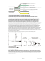
NEP9504G Shown
ANALITE
NEP9000 AND NEP9500 SERIES
TURBIDITY PROBE
USER MANUAL
V2.21 © 2007
ABN 56 007 28 96
58 Geddes Street, PO Box 298, Mulgrave
Victoria, AUSTRALIA, 70
Tel: (+6-) 9582-7, Fax: (+6-) 9560-64
E-mail: [email protected], Internet: www.mcvan.com
N827
Page V2.21 © 2007
V2.21 © 2007
Page ANALITE NEP9000 and NEP9500 Series Turbidity Probe User Manual
Introduction
Thank you for purchasing an ANALITE NEP9000 or NEP9500 series turbidity probe. It will give you years of service if
you install and maintain it according to guidelines set out in this Manual.
The ANALITE NEP9000 and NEP9500 series of turbidity probes are an enhanced version of our successful ANALITE
190 and 195 series probes. They offer better performance, more output options and greater ease of deployment yet
are available in the same mechanical package (G version).
The ANALITE NEP9000 and NEP9500 series turbidity probes are designed for monitoring and process applications
where turbidity levels of up to 3,000NTU may be encountered. Standard ranges are 100NTU, 400NTU and 1,000NTU,
but custom ranges are available.
Specifically, the ANALITE NEP9000 probes are designed for applications that will not allow bio-fouling to build up such
as short monitoring deployment or placement in fast and cold running water. The ANALITE NEP9500 probes however,
with their integral wiper assembly, are designed where bio-fouling or sedimentation buildup is likely. The ANALITE
NEP9000 and NEP9500 series of probes with a stainless steel case may be submerged to a depth of 100 meters
(approx. 330 feet). The composite case version is rated to 30 meters (approx 100 feet).
The ANALITE NEP9000 and NEP9500 probes use 90° optics and employs infrared light in accordance with ISO7027.
All probes use a unique modulation technique that ensures almost total rejection of ambient light conditions as well as
a unique microprocessor controlled differential sample and hold circuit for enhanced performance particularly at low
turbidity levels.
Applications
The applications that the ANALITE NEP9000 and NEP9500 probes are so extensive and too numerous to elaborate
on in this document but generally they include:
1) Monitoring of streams and rivers.
2) Monitoring of water storage bodies including stratification studies.
3) Intermediate and final effluent treatment monitoring.
4) Hydrological run off studies.
5) Ground and bore water analysis.
6) Drinking water filtration efficiency.
7) Industrial process monitoring.
8) Sludge and dredge monitoring.
9) Sediment load monitoring.
Which model is best used is dependent on the application, the measuring environment, the logging equipment and the
monitoring period (deployment times) required.
The ANALITE turbidity probes are not suitable in situations where they may be abraded by large particles such as
sand and under these circumstances the reading may become erratic due to the large particles passing the optic
sensor. Measuring turbidity under these circumstances will require a stilling well to allow the sand particles to settle
away from the optic sensor in the probe tip.
Page V2.21 © 2007
Specifications
Parameter
Measurement
NEP9001/9501
Technique
ISO7027 - 90°
Range
100NTU
Output Span
Response Time
Linearity
Zero Offset, 0 to 40°C
Repeatability @ 25°C
Temperature Coefficient
(0 to 40°C)
Calibration compliance
using APS AEPA
polymer solutions
NEP9004/9504
NEP9010/9510
NEP90xx/95xx
400NTU
1,000NTU
Custom to
3,000NTU max.
±2.5Volts or 4 – 20mA, where -2.5V or 4mA = 0NTU
0 to +1V and 0 to +2.5V outputs are also available. Specify output at time of order.
Approx 1 second to 99%.
1%
1%
3%
5%
±3mV max.
±1%
±1%
±2%
±2%
< ±0.05%/°C
4 points
0, 10, 40 and
100NTU
4 points
0, 40, 100 and
400NTU
4 points
0, 100, 400, and
1000NTU
3 points min.
0 and 2+ other
values.
Physical (Standard Version – see Physical Dimensions)
Probe Diameter
Probe only Length
Overall Length
Weight (probe only)
Cable
Connector
Cable Length
Environmental
Static Depth Rating
Operating Temp.
Storage Temp.
Wiper
Wiper Arrangement
NEP9500 series only
Actuation
NEP9500 series only
Actuation Pulse Duration
Actuation Pulse Current
Sink
Wiping Time
Power
Operating Voltage
Current Consumption
Power Settling Time
Wiping Current
Accessories
NEP19WIPE
NEP390-CA-xx
NEP19SHRD
NEP-CBL-xx
Note:
V2.21 © 2007
32mm for 316 stainless steel casing; 34mm for composite casing.
181mm without wiper, 188mm with wiper.
267mm without wiper; 274mm with wiper
120gms without wiper, 190gms with wiper.
5 core + shield. 6mm dia. PUR sheathed.
7 pin male waterproof to 100m when mated. Open face pressure of 50m
Specify at time of order. Cable part number is NEP-CBL.
100m (stainless steel casing), 30m (composite casing)
-5°C to +40°C
-20°C to +50°C
Disposable and consumable - Foam Pad on PVC or Acetal arm. Field replaceable.
Mounted on central shaft, fixed by hex set screw onto flat of wiper shaft.
1. By external TTL/CMOS active low pulse or momentarily contacting the wiper
actuation conductor (pin 5) to 0V (pin 3).
2. Automatic wipe every 2 hours if the wiper actuation conductor (pin 5) is
permanently connected to 0V (pin 3) and also when applying normal power to
the probe.
On NEP9500 series only.
>50mSec, <500mSec
On NEP9500 series only.
1mA max.
On NEP9500 series only. 8 second nominal.
During the wipe the output is held to the output value just prior to the wipe ±1% .
9.6 - 28V dc
15mA maximum when not wiping plus up to 20mA if current output fitted.
< 1 Sec
NEP9500 series only. Additional 25mA approx at less than 30m submersion.
Wiper Kit comprises 4 replacement wipers and hex fastening key for the ANALITE
NEP9500 series only. Also used on the ANALITE NEP195, 395 & 495 probes.
Shielded multi-core cable assembly including mating connector to suit the standard
version. Length xx to be specified at time of probe order.
Stainless protective shroud to suit the NEP9000 and NEP9500 series.
Cable only xx meters - specify at time of order. Required for G version.
The standard version utilises the water proof connector. The version utilising a fixed
and glanded cable includes the “G” suffix after the part number (eg NEP9504G).
Page Installation
There are two aspects to consider when preparing to install the ANALITE NEP9000 or NEP9500 series probes in the
field.
1) Installation of the probe proper into the environment where measurements are to take place.
2) Cabling considerations.
3) Connection of the probe into the data collection and control system.
Probe Installation
The probe is normally installed with the optics pointing downwards (but not vertical) or in a horizontal
alignment. In a simple application the probe is simply immersed into the water to the desired depth, but
within the depth rating of the probe. Please note the depth rating is based on static water. Allowances
must be made for the effect of flowing water to ensure the static depth rating is not exceeded. If the probe
is to be installed downwards then it is recommended to install it a few degrees away from the vertical to
allow bubbles to escape away from the optic face.
Probes with integrated wiping should be installed such that they can be easily retreived from time to time
to replace the wiper arm assembly.
It is important that the optic end of the probe is kept clear of obstruction such as the river bed. The
minimum distance between the optic head and any object should be 50mm (2”).
The standard casing of the ANALITE NEP9000 and NEP9500 series probes are made of 316 stainless
steel but the optic face is made of plastic materials and so should be protected from accidental scratching
or abrasion. The wiper arm assembly should be replaced periodically to avoid abrasive material build-up
in the pad that may eventually abrade the optic face. The optic face is partially protected from damage by
the protruding castellations in the probe casing.
To avoid crevice corrosion on the 316 stainless steel casing in salt and acidic water deployments it is
strongly recommended that the probe be thoroughly washed in clean water after deployment and prior
to storage. Failure due to crevice corrosion is not covered under warranty. A composite cased version is
available for corrosive and sea water environments but its pressure rating is limited 30m.
If the probe body is to be installed in a glanded fitting (for insertion into a pipe etc.) then care must be
taken to ensure the sealing surface pressures offered by the gland fitting are not excessive so as to not
cause distortion of the probe casing and force leakage. The ANALITE NEP9000 and NEP9500 series
probes are thin wall instrument and so glanding pressure must be minimal and spread over the largest
possible area. Do not cut or damage the outer sheath of the cable. Water may enter the probe through
holes or cuts in the cable sheath.
Where damage may occur due to river rocks striking or rolling over the probe body, a protective shroud
should be used which can be made of simple PVC piping or stainless steel which ever the situation
warrants. A shroud is available for the NEP9000 and NEP9500 as an accessory under the part number
NEP19SHRD. Such a shroud not only protects the probe but also assist in maintaining a minimum
distance between probe optics and any local obstructions.
Cabling Considerations
Physical
Cable normally supplied with the ANALITE NEP9000 and NEP9500 series probes is a specially selected
PUR sheathed and screened cable selected for strength, chemical resilience and exceptional resistance
to cuts, nicks and abrasion. The cable part number is NEP-CBL.
Never the less, care should be taken during the installation process of the probe and its cabling to ensure
that the cable is not subjected to persistent pulling, snagging, abrasion or severe compression. This is
particularly important for the probes with fixed and glanded cable as any water penetration through the
cable sheath may find its way into the probe proper affecting the accuracy of the readings and possibly
causing irreparable damage.
For probes fitted with connectors care must be taken to ensure the connectors are properly mated to
ensure a seal yet not screwed together too tightly so as to make their disconnection difficult after a long
deployment. Prior to mating make sure both the probe and cable connectors are dry in the termination
area otherwise erratic operation may occur due to moisture.
Page V2.21 © 2007
Electrical
Because long cable lengths are common some electrical factors should be taken into account and these
are discussed below.
Voltage Output Version
ANALITE NEP9000 and NEP9500 probes may have an analogue voltage output with a nominal output
impedance of 100 ohms. Conductor resistance is nominally 73 ohms/km or 7.3 ohms for 100 meter probe
cable and this may need to be taken into account in some configurations particularly with regards to
logger channels that have low input impedance (say less than 10,000 ohms). For particularly long cable
runs, the 4 – 20mA current output version is recommended.
4 – 20mA Current Output Version
ANALITE NEP9000 and NEP9500 probes may have an analogue 4 – 20mA current output with a
maximum load rating of 350ohms, consequently cable loop resistance should be taken into account. The
PUR cable normally supplied with the probes has a nominal loop resistance of 14.6 ohms per 100m. A
schematic of the probe and its load is shown below.
For very long cable runs (>200m), it may be advisable to connect the the NTU Return conductor to the
Supply Common conductor at the end of the cable to reduce the voltage drop along the run.
Surge and Lightning Considerations
Surge and lightning protection may also have to be considered given that many installations are “in the
wild”. It is important to note that the NEP9000 and NEP9500 series probes have the stainless steel casing
terminated only to the cable shield. There is no electrical contact between the casing and the probe
electronics. The signal ground (4) and power ground (3) are electrically bound together within the probe.
Probe Connection
The standard version of the NEP9000 and NEP9500 probes are fitted with a 7 pin male marine connector
with an open face pressure rating of 50m. This means that if the probe is accidentally submerged when
not connected, or improperly connected to its mating cable assembly, a pressure rating of only 50m is
offered. The mating female cable connector is supplied with the specifiied cable length. When the cable
connector is properly mated to the probe the overall pressure rating is 100m.
A fixed and glanded cable version is also available and these versions have the G suffix attached to the
part number.
The cable conductor assignment is as shown below:
Note that the Signal Common (yellow) and Supply Common (green) conductors are electrically connected
together within the probe. The stainless steel cover is connected only to the cable shield.
The probe is designed to operate with most data loggers, PLC and DAS systems available today. When
using the NEP9500 models some form of wiper actuation control may be required depending on the
wiping protocol selected. This is discuss later in this manual.
V2.21 © 2007
Page Pin 2 - BROWN
Pin - GREEN
Pin 5 - GREY
NEP90xx PROBE
OR
NEP95xx PROBE
SHIELD
Pin - WHITE
NO WIPE FUNCTION
ON NEP90xx PROBES
Pin 4 - YELLOW
9.6 - 28VDC SUPPLY +VE
0V SUPPLY COMMON
PROBE RESET- NEP9000
PROBE RESET/WIPE/AUTO WIPE - NEP9500 ONLY
NO CONNECTION WITHIN PROBE
NTU OUTPUT (V or I+)
NTU COMMON (V) or RETURN (I-)
There are two wiping protocols available on the NEP9500 probes:
1. A single wipe externally initiated by momentarily reseting the probe.
2. An automatic wipe every two hours by terminating the Reset/Wipe to the Power Common..
1. The wiper on the NEP9500 probes can be actuated by momentarily connecting the Reset/Wipe
conductor (5) to the Power Common conductor (3) for longer than 50msec but less than 0.5 second.
This has the effect of resetting the probe which then initiates a wipe immediately after the inbuilt
microprocessor has properly reset.This protocol can be implemented using a mechanical switch
arrangement or open collector (drain) output available on most loggers. For multiple wipes each
consecutive wipe must be actuated after the wiper has parked in its rest position (approx. 8 seconds after
a wipe actuation). Reset/Wipe pulses applied during a wipe action will be ignored. Note that during the
wipe period the NTU output will be held at the value measured just prior to the wipe (within 1%).
The recommended external wiper activation interface arrangements are shown schematically below.
2. Permenately connecting the Reset/Wipe conductor (5) to the Power Common (3) will force an
automatic wipe every two hours and when the probe power is applied. Note that during the wipe period
the NTU output will be held at the value measured just prior to the wipe (within 1%). Output from the
probe during the initial wipe on a power up should be disregarded and data treated as valid, say, about 12
seconds after the power is applied.
The termination arrangement for the 2 hourly auto-wipe is shown schematically below.
+5V
4k7
To
Wiper Actuation
Circuitry
470
Auto-wipe
every 2 hours
Grey
Single wipe activation
by external means
5
N.O.
R
>50mS, <500mS
0V
Green
NEP9500 SERIES PROBE
Switch
Actuation
Typical Semiconductor
Actuation
Current Output Arrangement
When a NEP9000 or NEP9500 series probe is ordered with the 4 – 20mA current output, the probe is
configured as a (high) current source. The load must be less than 350 ohms to ensure proper operation
over the probe’s specified power supply range. The connection arrangment for a probe with a current
output is shown below.
Page V2.21 © 2007
Pin 2 - BROWN
9.6 - 28VDC SUPPLY +VE
Pin - GREEN
0V SUPPLY COMMON
Pin 5 - GREY
NEP90xx PROBE
OR
NEP95xx PROBE
PROBE RESET- NEP9000
PROBE RESET/WIPE/AUTO WIPE - NEP9500 ONLY
SHIELD
NO CONNECTION WITHIN PROBE
Pin - WHITE
NO WIPE FUNCTION
ON NEP90xx PROBES
+
Note: Pins and 4 are
connected together within the
probe.
CURRENT OUT (4-20mA)
4-20mA Monitor/Display
50 ohm impedance
maximum
Pin 4 - YELLOW
-
CURRENT RETURN
Connection to the ANALITE TM5
The NEP9000 and NEP9500 series are readiliy interfacable to the
ANALITE TM5 Indicator/Controller unit the probe output must be
either ±2.5V or 4-20mA. The ANALITE TM5 is ideal for industrial
control and alarm applications. The ANALITE TM5 allows for the
selection of wiping intervals as well as allowing field calibration.
More information on the ANALITE TM5 can be downloaded from the
McVan Instruments website at www.mcvan.com.
Normal termination of a NEP9000 or NEP9500 series probe with ±2.5V output to an ANALITE TM5 is as
tabled below:
ANALITE NEP9xxx Probe
Pin
1
2
3
4
5
ANALITE TM5
Colour
White
Brown
Green
Yellow
Grey
Term No.
46
44
43
45
47
Circuit
NTU Vout Signal
+12Vdc Power
Power Common
NTU Vout Common
Clean (Wipe) – NEP95xx only
If the TM5 is fitted with the 4-20mA input option, a NEP9000 or NEP9500 series probe with current output
may be terminated as tabled below:
ANALITE NEP9xxx Probe
Pin
1
2
3
4
5
V2.21 © 2007
ANALITE TM5 with 4-20mA option
Colour
White
Brown
Green
Yellow
Grey
Term No.
50
44
43
51
47
Page Circuit
NTU I+ Signal
+12Vdc Power
Power Common
NTU I- Signal
Clean (Wipe) – NEP95xx only
Wiper Replacement
This applies to the NEP9500 versions only.
The effectiveness of the wiper in maintaining a clean optical surface will eventually be compromised, the time being
dependent on the water under investigation and the number of wiping cycles carried out. We recommend periodic
inspection of the wiper pad to determine if the material is deteriorating or is impregnated with material from bio-fouling.
Normally the wiper should be replaced every 4 to 6 weeks of deployment. In addition, as a precaution we recommend
changing the wiper prior to each deployment.
The wiper is a consumable item and a spare is provided with each NEP9500 series probe along with a hex key to
loosen and fasten the wiper set screw. Wiper packs containing four wipers and a hex key are available (Part Number
NEP19WIPE) as a standard accessory.
To change the wiper, loosen the set screw in the wiper arm until the wiper assembly can be removed from the
wiping shaft. Place a new wiper assembly on the shaft with the set screw aligned squarely with the flat on the wiping
shaft. Gently press the wiper arm down until the wiper arm hits the stop on the shaft. The wiper pad should now be
compressed to roughly one half its original thickness. Tighten the set screw - do not over tighten.
It is important that the wiper arm does not make contact with the probe face - only the pad should be in contact. A gap
of 0.5mm between the wiper arm and the optic face is typical when a new pad has been properly installed.
NOTE:
It is imperrative that the set screw be fastened squarely aligned onto the flat on the shaft otherwise
proper operation will be affected.
CAUTION: Do not over tighten the set screw or manually attempt to rotate the wiper arm once set onto
the shaft. Any attempt to manually rotate the wiper may cause gearbox damage and void the
warranty.
Calibration Confirmation and Turbidity Standards
The ANALITE NEP9000 and NEP9500 probes are factory calibrated using non-toxic neutral-density polymer-based
turbidity standards. Solution values up to 1,000NTU as USA EPA certified.
10NTU, 40NTU, 100NTU, 400NTU and 1,000NTU neutral-density polymer-based turbidity standards are available
from McVan Instruments and their distributors, or directly from the manufacturer for US customers only. We
recommend the use of one of these standards and pure water for a calibration confirmation. The standards should not
be diluted, as this will reduce the effect of the anti-fungal agent contained in the standard solutions.
Because a turbidity probe is inherently an optical device, care must be taken during a
calibration confirmation to ensure that external optical effects are kept to a minimum.
This is best implemented by placing calibration solutions in dark, leak proof bottles with
a non-reflective finish such as Nalgene® 2106 bottles in amber. These are available
from McVan Instruments with wide necks and a nominal capacity of 1,000ml and
carry the part number NEP-BTL. The calibration routine is best done under natural or
incandescent lighting (not fluorescent or arc).
Another critical factor is cleanliness. Any debris or water that makes its way into the
calibration solutions will affect its value. It is therefore a good practice to have an
ample supply of distilled de-ionized water and a means of properly drying the probe
end (clean compressed air is ideal). Wipers should always be removed prior to a
calibration routine. Probes should be flushed in two containers of distilled water with thorough drying in between and
before insertion into a calibration solution. Also where ever possible, a calibration confirmation should commence at a
lower value (usually zero) and work up in value to further minimize the effects of cross contamination.
CAUTION: ALWAYS REMOVE THE WIPER PRIOR TO CALIBRATION.
When inserting the NEP9000 or NEP9500 probe into a calibration solution ensure that the optic face of the probe is
at least 50mm from the base and all sides of the bottle. This is particularly important for low turbidity solutions below
200NTU. Hold the probe a few degrees from the vertical and gently tap it on the bottle rim so as to dislodge any air
bubble on the optic face. If the probe is properly placed the measurement value will not vary if the probe is gently
moved a few millimeters in any direction.
Page V2.21 © 2007
Physical Dimensions
NEP9000 and NEP9500 Probes
Warranty
The ANALITE NEP9000 and NEP9500 series turbidity probes are warranted against defects in material and
workmanship for one year from date of purchase, exclusive of the wiper assembly. The warranty does not cover the
wiper arm assembly, corrosion or leakage due to corrosion. Unauthorized service, tampering or abuse will void this
warranty. Damage as a result of improper installation will also void this warranty.
Should you require service (under warranty or otherwise) please contact the McVan Instrument distributor from whom
you purchased the probe, or our Service Centre. If the probe is being returned for service under warranty please
supply proof of purchase.
All support enquiries must include the serial number of the probe – labelled on the casing of the probe.
The shipping address for probe returns is:
McVan Instruments’ Service Centre
58 Geddes Street, Mulgrave
VIC 3170 AUSTRALIA.
Tel: (+61-3) 9582-7333, Fax: (+61-3) 9560-1164
E-mail: [email protected]
V2.21 © 2007
Page 10
Electrical Conformity
EC Declaration of Conformity
according to Council Directive 89/336/EEC
We, McVan Instruments Pty Ltd, declare under our sole responsibility that the product:
Analite NEP9000 and NEP9500 SERIES of turbidity probes and accessories,
Manufactured by:
McVan Instruments Pty Ltd
To which this declaration relates, are in conformity with the protection requirements of Council Directives 89/336/
EEC on the approximation of the laws relating to electromagnetic compatibly.
This Declaration of Conformity is based upon compliance of the product with the following harmonised
standards:
Emissions:
Immunity:
EN50081-1:1992
EN50082-1:1997
Signed by:
John Van de Vreede – Director
Date of Issue:1 DECEMBER 2002
Place of Issue:
McVan Instruments Pty Ltd
58 Geddes Street, Mulgrave
VIC 3170 Australia
N827
ABN 56 007 28 96
58 Geddes Street, PO Box 298, Mulgrave
Victoria, AUSTRALIA, 70
Tel: (+6-) 9582-7, Fax: (+6-) 9560-64
E-mail: [email protected], Internet: www.mcvan.com
Page 11
V2.21 © 2007
Protection Shroud
90 mm for NEP260 probe
20mm for NEP9xxx probes
9 mm
40 mm
5 mm
INSERT
PROBE
OD8.2mm
off M4 x 8 hex SS set-screws @ 20°
to fasten to probe end.
Flow through holes
(approx .5 dia)
FITTING
Insert the Analite turbidity probe into the shroud as shown.
Ensure end of probe is against internal stop at other end of shroud.
Rotate the probe in the shroud so as to give the
lowest possible (NTU) output when in clear water.
Fasten the M4 screws onto the probe end. (Do not over tighten).
Re-zero the instrument with the shroud fitted.
Approximate weight of the shroud alone is 400grams
Material: 6 Stainless Steel
© 999 - 2005 McVan Instruments Pty Ltd
File: NEP SHROUD for NEP60 and NEP9xxx.cdr
Product Identification Nomenclature
POLARITY
Omit = ±2.5v
U = Unipolar +1v or +2.5V
Omit = Current output
NEP9
OUTPUT
V = Voltage
I = Current
CASING
Omit = Stainless steel
P = Composite
X
Examples:
WIPING
0 = Non-wiping
5 = Wiping
RANGE
01 = 100NTU
04 = 400NTU
10 = 1,000NTU
30 = 3,000NTU
UNIPOLAR
A = 0 - 1v
B = 0 - 2.5v
Omit = ±2.5v
Omit = Current output
CONNECTOR
Omit = Connector
G = Fixed glanded
cable.
Omit means that character is completely left out of the product code if the indicated
parameter is required (see examples).
IS. C/N
NEP9010UBXVP
Probe without wiping, 1000NTU range with
standard connector and unipolar 0 - 2.5v voltage
output. Casing is composite.
NEP9501GXI
Probe with wiping, 100NTU range with glanded
cable fitted and 4-20mA current output. Casing is
stainless steel.
©
DATE
Tolerances:
Lin ±0.2mm,
Ang ±0.5°.
Unless otherwise stated.
ABN 56 007 28 96
58 Geddes Street, PO Box 298, Mulgrave
Victoria, AUSTRALIA, 70
Tel: (+6-) 9582-7, Fax: (+6-) 9560-64
E-mail: [email protected], Internet: www.mcvan.com
V2.21 © 2007
NEP9504GXV
Probe with wiping, 400NTU range with glanded
cable fitted and ±2.5v voltage output. Casing is
stainless steel.
Page 12
2005
Copyright
Status
P
NEP9xxx PRODUCT IDENTIFICATION
NOMENCLATURE
25/2/05
DRN KH
SHEET SCALE DWG No. ISS
TBA
NTS
1 OF 1
B
APP JVdV 25/2/05
File: NEP9xxxX Conductor Assignment.cdr, 2/05