1
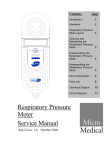
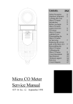
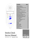
Contents
Safety Precaution
Important safeguards
Looking after your Baby CO meter
Introduction
Before you begin
Baby CO system overview
CO sensor
Baby CO meter exploded view
Disassembling the Baby CO
meter for servicing
Replacing the internal battery
Replacing the fuel cell
Reassembling the Baby CO meter
Calibrating the Baby CO meter
Circuit description
Power supply
Fuel cell amplifier circuit
Reset circuit
Display
Sounder
Indicator lights
RS232 interface
Specifications
Technical support
Parts List
Circuit Diagram
FCOHb
CO
OFF
Baby CO Meter
Service Manual
113-19 Iss. 1.0
page
Jan 2007
2
2
2
2
2
3
5
6
7
7
7
8
9
11
11
12
12
12
12
13
13
14
15
16
18
Baby CO Meter
Service Manual
Information in this document is subject to change without notice and does not represent a commitment
on the part of Micro Medical Limited. Only the parts supplied by Micro Medical Limited should be used
to complete the service operation described in this manual. If in any way you feel unsure about the
successful completion of the service operation you should contact Micro Medical Limited or its
appointed agent in your country or region and arrange the despatch of the product to a Micro Medical
Limited Service Centre.
Copyright 2005 by Micro Medical Limited All rights reserved
Drawing no. 113-19
Version 1.0
September 2007
All other products are trademarks or registered trademarks of their respective owners.
1
Safety Precaution
The servicing of this device is intended to be carried out by a properly trained and
competent electronics engineer, or experienced in the maintenance and servicing
of medical devices. Read this manual thoroughly before proceeding with the
service. If in any doubt please contact the service centre at Micro Medical Limited
or their accredited agent in your country or region.
Important Safeguards
ο Read all of the instructions.
ο Keep the instructions in a safe place for later use.
ο Follow all warnings and instructions marked on the product.
ο When replacement parts are required, be sure to use replacement parts
specified by Micro Medical that have the same characteristics as the original
parts. Unauthorised substitutions may result in fire, electric or other hazards.
ο Do not place on an unstable table.
ο The product should be operated only from the type of power source indicated
on the label.
Looking after your Baby CO Meter
ο Avoid exposing the Baby CO Meter to solvents including alcohol and
disinfectants.
ο Avoid operating the Baby CO Meter in dusty conditions or near to heating
appliances or radiators.
ο Do not keep the Baby CO Meter in a damp place or expose it to extreme
temperatures.
Introduction
This service manual provides you with information to carry out the servicing of the
Baby CO Meter. It is a process, which is relatively straightforward but must be
carried out in a logical sequence. Our advice is to familiarise yourself with the
contents of this manual before attempting to carry out the procedure of replacing
the parts supplied in the sensor replacement kit for the Baby CO Meter.
Before You Begin
Before you begin the servicing operation, please read the section on Circuit
description very carefully:
2
Baby CO Meter system overview.
The Micro Medical Baby CO meter consists of a hand held microcomputer
unit (1) incorporating a CO sensor and is supplied with a mouthpiece
adapter with integral one way valve (2) together with disposable cardboard
mouthpieces (5).
The microcomputer unit is powered by a single alkaline PP3 battery (4)
and is supplied with a reducing connector for calibration (3).
1
2
3
FCOHb
CO
OFF
4
5
6
3
The CO sensor is an electrochemical fuel cell, and works through the
reaction of carbon monoxide at one electrode and oxygen (from ambient
air) at the other. This reaction generates an electrical current proportional
to the concentration of CO exposed to the sensing surface of the fuel cell.
The current output signal from the sensor is conditioned using a current to
voltage converter and is applied to an analogue to digital (A/D) converter.
When the unit is first switched on the microprocessor records the baseline
reading on the A/D input and uses this value to auto zero the instrument.
The subject is requested to breathe in maximally, hold the breath for 10
seconds, and then to expire fully through the mouthpiece connected to the
microcomputer unit with the mouthpiece adapter. As an aid to timing the
breath holding period a countdown from 10 to 0 is displayed after the unit
is turned on.
The microprocessor then records the peak value obtained and displays
this on a 3½ digit LCD display.
The value can be displayed either as parts per million (ppm) concentration
in the expired air or as the equivalent percentage carboxyhaemoglobin
(%COHb) using the mathematical relationships described by Jarvis et al,
for concentrations below 90ppm and by Stewart et al for higher
concentrations.
Jarvis MJ, Belcher M, Vesey C, Hutchison DCS
Low cost carbon monoxide monitors in smoking assessment.
Thorax 1986; 41:886-887
Stewart RD, Stewart RS, Stamm W, Seleen RP
Rapid estimation of carboxyhaemoglobin levels in fire fighters
JAMA 1976; 235:390-392
As a quick guide to the estimated smoking level, red, amber and green
indicator lights are provided. The following levels of CO activate these
lights:
CO(ppm)
%COHb
Cigarette consumption
Indicator
0-5
0 - 0.8
Non smoker
Green
6 - 10
1 - 1.6
Light smoker
Amber
11 - 72
1.8 - 12
Heavy smoker
Red
>72
>12
Suspected poisoning
Red + alarm
4
CO Sensor
The sensor is an electrochemical micro fuel cell using gaseous diffusion
barrier technology resulting in a direct response to volume concentration
rather than partial pressure.
The cell consists of a working electrode and a counter electrode separated
by a thin layer of electrolyte. The gaseous diffusion barrier limits the flow
of gas to the sensing electrode and ensures the electrochemical activity of
the electrode is far in excess of the amount of gas with which it has to
deal.
Gas diffusing onto the working electrode reacts at the surface of the
electrode by oxidation.
CO reacts at the working electrode according to the equation:
CO + H2O → CO2 + 2H+ + 2eThe counter electrode acts to balance out the reaction at the sensing
electrode by reducing oxygen in air to water:
½O2 + 2H+ + 2e- → 2 H2O
5
Baby CO meter exploded view
Item 6 Item 5
Item 4
Item 3
Item 9
Item 10
Item 7 Item 8
6
Item 2
Item 1
Disassembling the Baby CO meter for servicing.
The Baby CO microcontroller unit comprises of a solid state electronic circuit
in a robust ABS housing and does not require any preventative maintenance.
Routine maintenance consists of replacing the fuel cell and internal lithium
battery when they are exhausted. The 3.6 volt lithium battery is continuously
monitored by the microcontroller and the message bt2 will be displayed when
the voltage falls below 3 volts. The fuel cell exhibits a gradual loss of
sensitivity with time and has effectively expired when the unit can no longer
be calibrated.
When either the fuel cell or the lithium battery has expired, replace by
following the procedure below.
1. Turn the unit face down and slide back the battery compartment.
2. Remove the PP3 battery.
3. Remove the 2 self tapping screws (Item 1) and put to one side.
4. Lift the top moulding (Item 6) from the bottom moulding (Item 2).
5. Remove the PCB (Item 3) from the bottom moulding.
6. If the fuel cell (Item 4) is exhausted carefully remove by gently pulling
away from the PCB.
7. If the battery (Item 8) has expired, then note the orientation and remove
from the PCB-mounted clips by pulling on the battery strap (Item 7) directly
away from the PCB. Put the battery strap to one side and discard the
battery.
Replacing internal battery of the Baby CO.
1 Place the battery strap over the new battery (Cat No: BAT5900) and push
into the PCB-mounted clips ensuring the correct orientation. (Take great
care not to short circuit the terminations even momentarily as the
low internal impedance of lithium batteries will result in a high
current consumption and greatly reduced life).
Replacing fuel cell of the Baby CO.
1 Remove the CO sensor (Cat No: CEL7300) from the plastic container.
2 Carefully insert the CO cell into the PCB with the correct orientation.
7
Reassembling the Baby CO meter
1. Place the PCB into the bottom moulding.
2. Tuck the battery strap between the battery and the side wall of the bottom
moulding, away from the slide switch.
3. Ensure that the slide switch (Item 9) and the switch plate on the top
moulding (item10) are both positioned at the bottom of their travel.
4. Ensure that the rubber gasket (Item 5) is in place in the top moulding.
5. Place the top moulding on top of the bottom moulding ensuring the rubber
gasket fits over the cell correctly and secure using the two self-tapping
screws.
6. Reconnect the PP3 battery ensuring correct polarity.
8
Calibrating the CO meter
Calibration will remain stable to within 2% over one month and typically to
within 10% over 6 months. Micro Medical supplies calibration gas (20ppm CO
in air) and recommends that the unit is recalibrated on a 6 monthly basis. See
page 13 for calibration accessories.
To carry out the calibration locate the calibration switch on the right hand side
of the instrument as shown below.
Serial
port
Calibration
Switch
Push the slide switch to the CO - PPM position and wait for the unit to display
zero.
9
Screw the control valve firmly onto the cylinder and connect the gas supply as
shown below:
Plastic Tubing
Control
valve
Flow
indicator
Reducing
Connector for
calibration
20 ppm carbon
monoxide in air
The plastic tubing supplied with the gas should be pushed firmly over the
reducing connector.
Slowly turn the control knob anti-clockwise until the ball in the flow indicator is
between the two marks. This will then supply a gas flow of approximately
0.25 l/min. Apply this flow for 25 seconds and if the meter does not read
20ppm use the calibration tool to push the calibration switch.
The unit will then beep 3 times, store the new calibration value, and display
the following:
The gas supply should then be turned off.
10
Circuit description
(Refer to the parts list and circuit diagram)
The circuit is based on the Hitachi one time programmable (OTP)
microcontroller HD64F3687FP (U5) operating at a clock frequency of
14.745MHz.
This processor contains EPROM, RAM, and eight 10-bit analogue to digital
(A/D) converters. The current output signal from the sensor is conditioned
using a current to voltage converter and is applied to an A/D input of the
microcontroller. Voltages derived from the external PP3 battery and the
internal lithium battery are also connected to the A/D converter inputs.
When the unit is first switched on the microprocessor records the baseline
reading from the A/D and uses this value to auto-zero the instrument. The
signal from the CO sensor is continuously monitored and the peak of the
calculated carbon monoxide concentration is displayed and transmitted
through the RS232 driver (U7).
Power Supply
The unit has two separate supplies. The externally accessible alkaline 9 volt
PP3 battery (BAT 1) provides the main supply. The instrument may be
switched on and off with the slide switch and may also be switched off by a
signal from the processor. This is done if the unit is left on, without use, for a
period of 4 minutes in order to conserve battery power. The supply is
controlled by gates U2 and U3 arranged in a bi-stable configuration, and
powered continuously from BAT1. When the slide switch is moved to the
‘CO-PPM’ position one end of R7 is pulled low. This transition is differentiated
by the action of C15 and R6 so that a momentary pulse appears on pin 2 of
U3. This pulse will toggle the bi-stable circuit so that pin 4 of U2 will go low,
turning transistor TR2 on, and supplying 9 volts to the low drop-out regulator,
U4. When the slide switch is returned to the ‘off’ position pin 1 of U2 is pulled
low, the bi-stable action is reversed, and TR2 will be turned off. If the unit is
left on without use for approximately 4 minutes then pin 44 of U5 is driven
high, under software control, turning on TR1 which will also turn the unit off
via the bi-stable circuit. When this happens the slide switch must be pushed
to the ‘off’ position and then to the ‘CO-PPM’ position in order to initiate
another pulse through C15 to turn the unit back on again. The output of the 5
volt regulator supplies the processor and associated circuitry. C13 and C14
smooth the input and output of U4.
BAT1 is monitored by an A/D input of the microcontroller, pin 62 through the
potential divider, R13 and R14. When this battery falls below 6.6 volts a
battery low warning is temporarily indicated on the display upon switch on.
When the battery falls below 6.1 volts the message is displayed permanently
and the unit cannot be used.
11
The secondary power supply is provided by a single 3.6 volt lithium cell,
BAT2, used to permanently power the fuel cell amplifier circuit consisting of
the op-amp U1 and associated passive circuitry. The amplifier circuit draws
less than 11uA from the 1000mA-Hr lithium battery giving a nominal
operational life of greater than 10 years.
BAT2 is buffered by U8B and monitored by an A/D input of the
microcontroller, pin 63. R27, between BAT2 and the inverting amplifier,
prevents the battery from discharging through the op-amp when the supply is
switched off. The battery has an end point of 3 volts and when this level is
reached the message bt2 will be displayed. When this happens follow the
procedure outlined in Servicing.
Fuel cell amplifier circuit.
The fuel cell provides an output current, from the counter electrode,
proportional to the concentration of target gas at the sensing surface. This
current is converted to a voltage by the action of U1 and the associated
passive components at a nominal transfer factor of 387mV/µA. This signal is
further amplified by U8A with a gain of 2.08 and applied the A/D input of the
microcontroller, pin 44, after being filtered by the action of R8 and C4. The
sensitivity of the CO fuel cell is 0.045 +/- 0.015µA giving a nominal amplified
output of 36mV/ppm CO.
Reset Circuit
This microcontroller has internal reset circuitry that requires C12 and D5 for
proper operation.
Display
The display is a custom 3½ digit low power LCD. The segments and
backplane are driven directly by microcontroller. The backplane is driven by a
square wave of nominally 60Hz. The individual segments are driven by a
similar square wave that is in phase with the backplane when the segment is
off and 180 degrees out of phase when the segment is on.
Sounder
The sounder is operated by a 1kHz square wave generated by pins 24 and 25
of U5.
12
Indicator lights
The three indicator LED’s are driven from pins 51, 52 and 53 of the
microcontroller through transistors TR3, TR4 and TR5.
RS232 interface
The transmit and receive ports for RS232 transmission are on pins 46 and 45
respectively of the microcontroller. The transmission is converted from logic
to RS232 levels by the U7.
13
Specifications
Type
Electro - chemical fuel cell
Range
0 - 100ppm
Resolution
1ppm
Green indicator light
0 to 6ppm (0 to 1% COHb)
Amber indicator light
7 to 10ppm (1.1 to 1.6% COHb)
Red indicator light
11 to 72ppm (1.8 to 12% COHb)
Flashing red light + alarm
>72ppm (>12% COHb)
Accuracy
+/-5% of full scale of 1ppm whichever
is the greater
Sensitivity drift
0.5%/°C
Sensor Life
>2 to 5 years
Response time
<15 sec (to 90% of reading)
Hydrogen cross sensitivity <15%
Operating temperature
15 to 25°C
Operating pressure
Atmospheric +/-10%
Pressure coefficient
0.02% signal per mBar
Relative humidity
15 – 90% continuous
(Non condensing)
(0 – 99% intermittent)
Baseline drift
0ppm (auto zero)
Long term drift
<2% signal loss per month
Power source
Single Alkaline 9 volt PP3
Main battery life
>30 hours of continuous use
Internal battery life
10 years
Weight
180g (Including battery)
Dimensions
170 x 60 x 26mm
Display
3½ digit LCD
Storage temperature
-20 to +70 deg Celsius
Storage humidity
30% to 90%
14
Technical Support
Great Britain and World Headquarters
Micro Medical Ltd
PO Box 6
Rochester
Kent ME1 2AZ
Telephone
+ 44 (0)1634 893500
Fax
+44 (0)1634 893600
Web Site
http://www.micromedical.co.uk
Email
[email protected]
Contact Micro Medical Ltd for the local agent in your region or
country for local service:
15
Parts List
Designation
U1
U2
U3
U4
U5
U6
U7
U8
D1
D2
D3
D4
D5
DISPLAY
TR1
TR2
TR3
TR4
TR5
R1
R2
R3
R4
R5
R6
R7
R8
R9
R10
R11
R12
R13
R14
R15
R16
R17
R18
R19
R20
R21
R22
R23
R24
R25
R26
R27
C1
C2
C3
C4
Description
OP90GS. Precision micro power surface mount
BU4S11. Single NAND gate
BU4S11. Single NAND gate
LM2931M5.0. Low drop-out 5 volt regulator
HD64F3687FP. Hitachi microcontroller
24LC00. 16 Byte surface mount serial EEPROM
MAX3221CAE. Maxim RS232 transceiver
MCP602-I/SN. Microchip dual rail-to-rail OP-AMP
ZHCS750 Schottky diode
3mm green LED
3mm red LED
3mm yellow LED
BAS21. Small signal diode
(LCD 016-03) 3½ Digit custom display
DTC114EKA NPN transistor
FMMT591 PNP transistor
DTC114EKA NPN transistor
DTC114EKA NPN transistor
DTC114EKA NPN transistor
330K Resistor
12K Resistor
1M Resistor
10K Resistor
10K Resistor
1M Resistor
1M Resistor
100K Resistor
10K Resistor
560R Resistor
560R Resistor
820R Resistor
100K Resistor
100K Resistor
100K Resistor
10K Resistor
1M Resistor
10K Resistor
10K Resistor
10K Resistor
27R Resistor
1K Resistor
10K Resistor
180K Resistor
360K Resistor
390K Resistor
1M Resistor
10µF Tantalum capacitor
22pF Ceramic capacitor
0.1µF Ceramic capacitor
1µF Ceramic capacitor
16
C5
C6
C7
C8
C9
C10
C11
C12
C13
C14
C15
C16
C17
C18
C19
C20
C21
TH1
SW1
SW2
BAT2
X1
CO CELL
22pF Ceramic capacitor
0.1µF Ceramic capacitor
0.1µF Ceramic capacitor
0.1µF Ceramic capacitor
0.1µF Ceramic capacitor
1µF Ceramic capacitor
0.1µF Ceramic capacitor
10nF Ceramic capacitor
0.1µF Ceramic capacitor
47µF Electrolytic capacitor
0.1µF Ceramic capacitor
33pF Ceramic capacitor
33pF Ceramic capacitor
1µF Ceramic capacitor
1µF Ceramic capacitor
0.1µF Ceramic capacitor
0.1µF Ceramic capacitor
NTC 47K thermistor
SLF2300. Double pole 3 position slide switch
Push switch
SL235 CVHZ Sonnenschein 1A-Hr ½ AA Lithium cell
14.745 MHz crystal
1000 ppm CO fuel cell
17
A
B
C
1
C10
1uF
R21
27R
5V
BAT1
PP3
2
3
1
2
C9
0.1uF
C7
0.1uF
C6
0.1uF
1
VIN
1
2
3
4
5
6
7
8
2
VOUT
U4
LM2931M-5.0
R16
10K
JP1
0.1uF
C13
8
10K
R4
C8
0.1uF
5V
100K
R14
100K
R13
FMMT591
TR2
1
ZHCS750
3
2
2
J1
JACK
MAX3221CAE
EN FOFF
C1+
5V
V+
C1 TO
C2+ FON
C2 - TIN
VINV
RIN RO
U7
CALIB_SWITCH
SW2
16
15
14
13
12
11
10
9
SPK1
+
5V
+
2
1
2
1
1uF
C18
2
1
C1
10uF
U2
5V
1
2
BU4S11
U3
BU4S11
5V
MODE
R5
10K
1
C14
47uF
4
4
5
3
5
3
C5
0.1uF
C3
10nF
C12
22pF
C2
22pF
R7
1M
18
1
3
ppm
D5
10K
R23
24LC00
SCL
SDA
U6
3
3
Vss
Vcc
2
5
5V
P37
P36
P35
P34
P33
P32
P31
P30
P67/FTIOD1
P66FTIOC1
P65/FTIOB1
P64/FTIOA1
P63/FTIOD0
P62/FTIOC0
P61/FTIOB0
P24
P76/TMOV
P75/TMCIV
P74/TMRIV
P72/TXD_2
P71/RXD_2
P70SCK3_2
P55/WKP5
P54//WKP4
P53//WKP3
P52//WKP2
P51//WKP1
P50//WKP0
P23
P85
P86
P87
SW1A
SLF2300
U5
H83687
1
OSC1
OSC2
RST
TEST
X2
X1
VCC
GND
VCL
AVCC
P17/IRQ3
P16/IRQ2
P15/IRQ1
P14/IRQ0
P12
P11/PWM
NMI
P22/TxD
P21/RxD
P10
P20/SCK3
PB0/AN0
PB1/AN1
PB2/AN2
PB3/AN3
PB4/AN4
PB5/AN5
PB6/AN6
PB7/AN7
P57/SCL
P56/SDA
P60/FTIOA0
BAS21
1
3
11
10
7
8
4
5V
5
12
9
6
3
54
LED3 53
LED2 52
LED1 51
25
24
35
46
45
percent
23
44
62
61
60
59
BATT2
63
64
1
2
27
26
36
RST
14.745
X1
0.1uF
R6
1M
C15
R17
1M
for MCU
C19
1uF
3
1
10K
R9
18
17
16
15
55
56
57
58
40
39
38
37
32
33
34
31
30
29
28
50
49
48
22
21
20
19
14
13
47
41
42
43
P85
P86
P87
SW1B
SWITCH_SLF2300
CELL
A3
F3
COHb
G3
B2
A2
F2
G2
B1
C1
D1
E1
DP2
E2
D2
C2
C3
D3
E3
G1
F1
A1
DP1
CO
FOETAL
B3
BLOW
F
BP
DTC114EKA
TR1
EcoSure-LXH
5
5V
2
4
D1
2
1
2
3
3
6
7
1
3
2
1
W
2
4
percent 20
19
18
17
16
15
14
13
12
11
10
9
8
7
6
5
4
3
2
1
R22
1K
4
C17
33pF
ppm
2
3
R20 10K
R19 10K
R18 10K
5V
DISPLAY_FOETAL
%
ppm
B1
C1
A1
COHb
F1
F
G1
D1
C2
E1
B2
DP1
A2
CO
F2
D2
G2
E2
C3
DP2
B3
BLOW
A3
D3
F3
E3
G3 FOETAL
NC
NC
NC
NC
NC
NC
NC
NC
NC
BP
DIS1
75K
0R
C21
0.1uF
R1
R2
0.1uF
C11
-
21
22
23
24
25
26
27
28
29
30
31
32
33
34
35
36
37
38
39
40
OP90
+
U1
10K
not used
R3
TH1
3.6V
7
4
1
5
8
D
1
7
6
R15
100K
5
1
Date:
File:
B
Size
R27
3
TR5
C4
1uF
+
-
1
LED2
7
LED3
1
D3
AMBER
R11
560R
5V
MCP602
U8B
DTC114KE
TR4
+
-
C20
0.1uF
DTC114KE
TR3
6
Revision
1.0
D4
RED
R12
820R
5V
6
9-Jan-2007
Sheet 1 of 1
G:\Development\113 - CO Meter with Foetal %COHb\Hardware\Foetal.ddb
Drawn By: D.G.Brown
Number
113-01
Foetal CO
5
6
BATT2
MCP602
1
U8A
390K
5V
R26
D2
GREEN
R10
560R
5V
1M
BAT2
BAT3.6V
33pF
C16
2
DTC114KE
3.6V
Title
LED1
R8
100K
360K
R25
180K
R24
5
1
2
8
4
C
6
8
3
2
3
2
3
2
A
B
C
D