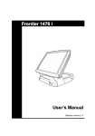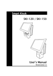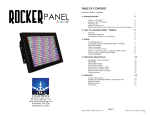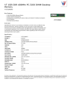
1
Flexible / Classy / High Performance
POS GT-150 Series
USER’S MANUAL
All-in-One Touch Screen POS System
Intel Pentium Mobile Motherboard, 15 inches LCD Monitor
Available in BLACK & SILVER colors
Preface
About this Manual
Thank you for purchasing POS GT-150 Series All-in-One system. This terminal offers all the
enhanced features and is easy to connect to various optional devices for optimal performance.
This user manual describes how you setup and connect your terminal.
Copyright
The information in this guide is subject to change without prior notice.
© Copyright 2008
All rights reserved. This product and related documentation are protected by copyright and are
distributed under licenses restricting their use, copying, and distribution. No part of this
documentation may be reproduced in any form by any means without prior written authorization
of the manufacturer and its licensors, if any.
ii
Preface
Federal Communications Commission (FCC)
Declaration of Conformity
This device complies with part 15 of the FCC Rules. Operation is subject to the following two
conditions:
1. This device may not cause harmful interference.
2. This device must accept any interference received, including interference that may cause
undesirable operation.
This equipment has been tested and found to comply within the limit of a Class A digital device,
pursuant to Part 15 of the FCC Rules. These limits are designed to provide reasonable protection
against harmful interference in a residential installation. This equipment generates, uses, and can
radiate radio frequency energy and, if not installed and used in accordance with the instructions,
may cause harmful interference to radio communications. However, there is no guarantee that
interference will not occur in a particular installation. If this equipment does cause harmful
interference to radio or television reception, which can be determined by turning the equipment off
and on, the user is encouraged to try to correct the interference by one or more of the following
z Reorient or relocate the interference receiving antenna.
measures:
z Increase the distance of separation between the equipment and interference receiver.
z Connect the equipment to a power outlet on a circuit different from that to which the
interference receiver is connected.
z Consult the dealer or an experienced radio/TV technician for help.
WARNING:
Use the included AC power cord so as not to interfere with radio and television reception.
If you use other cables, it may cause interference with radio and television reception.
WARNING:
TO PREVENT FIRE OR SHOCK HAZARD, DO NOT EXPOSE THIS APPLIANCE TO RAIN OR MOISTURE.
WARNING:
This is a equipment of Class A. This device could cause interferences in residential areas; in the case of interferences
it can be demand from the user to provide appropriate solutions for it.
WARNING:
The use of shielded cables for connection of the monitor to the graphics card is required to assure compliance with
FCC regulations. Changes or modifications to this unit not expressly approved by the party responsible for
compliance could void the user’s authority to operate this equipment.
RoHS
iii
Important Safety Information
BEFORE YOU PROCEED
z Read the safety notices and the User’s Manual carefully before using the product.
z Keep the box and packaging in case the product needs to be shipped in the future.
z Follow the product and warning label instructions.
z For safety reasons, only qualified service personnel should open the terminal.
z Any changes or modifications that do not follow the instructions in this manual will void
this product/s warranty.
! SAFETY PRECAUTIONS
In the interest of safety, please observe the following precautions:
Power Requirement:
This product is designed to operate on 230V AC 50/60Hz in Europe.
Never connect to any outlet or power supply having a different voltage or frequency.
! POWER SUPPLY SAFETY NOTICE
z Disconnect this terminal from the AC outlet before cleaning. Use only a moistened cloth for
cleaning.
z Check the voltage of the power source when connecting the equipment to the power outlet.
Make sure the voltage of the power outlet conforms within voltage range of the terminal.
Failure to comply may cause the electric shock or damage to the terminal. If you are not sure
of the electricity voltage that you are using, contact your local electricity company.
z To avoid electric shocks, disconnect the power cord from the electrical outlet before
relocating the system.
z Do not overload electric power outlets to avoid fire or electric shocks.
z Protect the power cord from being walked on or pinched particularly at plug.
z If the equipment is not used for a long time, disconnect the equipment from the mains to
avoid damage.
z Never allow liquid into ventilation openings. This could cause fire or electrical shock.
iv
Important Safety Information
! OPERATING INSTRUCTIONS
z Keep the User’s Manual for future reference.
z Follow the product label instructions.
z Lay this terminal on a stable surface when installing. Heavy objects placed on the product
can cause damage or obstruct proper ventilation.
z If one of the following situations arises, notify a qualified service technician immediately:
a. The power cord or plug is damaged.
b. Liquid has been split on to the terminal.
c. The terminal has been dropped and damaged.
d. The terminal does not function according to the user manual.
e. The terminal has obvious signs of damage.
z Ventilation slots and holes are provided on the sides of this unit. Do not block any
ventilation openings to prevent the equipment from overheat.
z Do not place the unit locations with high humidity and dust. They can cause extensive
damage. Avoid places where unit is likely to be exposed to oily fumes and vapors.
z Places exposed to direct sunlight, or near heating appliances can attain extremely high
temperatures, which may deform the cabinet, or can become a prime cause of damage.
z The operating ambient temperature range is 41 ゚ F - 104 ゚ F (0 ゚ C to 40 ゚ C), and humidity of
10% - 90%. When using the unit on the system rack, be sure to keep this ambient
temperature inside the range.
z Avoid shaky places or hot-springs areas where hydrogen sulfide and acidic ions are likely to
be generated.
z When transporting this unit, make sure it is not likely to be subjected to impacts. They can
be a prime cause for damage.
v
Table of Contents
CONTENTS
1. Introduction......................................................................................................................................1
Welcome.......................................................................................................................................1
1.1 How to Use This Manual ...............................................................................................1
1.2 A Visual Tour of POS GT-150 Series Terminal..............................................................2
1.2a What Comes With POS GT-150 Series Terminal.................................................4
1.2b Dimension 15” .....................................................................................................6
1.2c Adjustable LCD Operation Angle ........................................................................7
1.3 Features ..........................................................................................................................7
1.4 Connector Panels............................................................................................................8
1.5 Switch Panels .................................................................................................................9
2. Hardware Setup..............................................................................................................................10
Getting Started ...........................................................................................................................10
2.1 Pre-installation Notice..................................................................................................10
Hardware Assembly ................................................................................................................... 11
2.2a COM power selection................................................................................................. 11
2.2b Compact Flash Installation…… ................................................................................12
2.2c Magnetic Stripe Reader Installation……...................................................................13
2.2d 3-in-1 Card Reader Installation…..............................................................................16
2.2e VFD Customer Display Installation….......................................................................19
2.2f WiFi Installation…… .................................................................................................22
2.2g RFID Installation……................................................................................................25
2.2h Wall Mount Installation…..........................................................................................28
CMOS Setup ..............................................................................................................................28
2.3 LCD and Touch Panel Replacement ............................................................................29
3. Specification ..................................................................................................................................32
Technical Information ................................................................................................................32
Motherboard Configuration .......................................................................................................33
vi
Introduction
1. Introduction
Welcome
Congratulations on your purchase of POS GT-150 Series Terminal. Your easy-to-use POS terminal
is designed to help you enhance your business flexibility by offering a superior customer
experience.
1.1 How to Use This Manual
This manual contains all the information needed for setting up a POS GT-150 Series Terminal. In
addition, you can also consult the manual for the operation system and added peripheral hardware.
z Provides an introduction to POS GT-150 Series Terminal and this user’s manual.
z Provides all necessary information for all hardware setup.
z List all the specifications of POS GT-150 Series Terminal and information for the
motherboard configuration.
z Provides information for troubleshooting POS GT-150 Series Terminal.
1
Introduction
1.2 A Visual Tour of POS GT-150 Series Terminal
Before you start, take a few moments to become familiar with POS GT-150 Series Terminal.
Elegant, Solid, Fashionable Compact Design
Easy to reach I/O Connector Ports
(Back Side of Machine)
Main Unit
VFD Mounting Cover
I/O Connector Ports Cover
2
Introduction
Available in 15”
TFT LCD Touch
Monitor
3 in 1 MSR
+
Smartcard
+
i-Button Reader
WIFI
Air Vent
(on both left and right sides)
Finger print-Free
Front Bezel Design
Auto Power Switch,
Bright Control Cover
Speak Hole
3
Introduction
“Very easy to Maintain”
Take ONLY 4 Steps to reach all the POS inner components:
Step 1:
Slide out the rear plate
Step 2:
Unscrew this screw
Step 3:
Slide the case outwards
Step 4:
Remove the rear monitor cover
1.2a What Comes With POS GT-150 Series Terminal
The following items are standard with POS GT-150 Series terminal.
Before setting up your POS GT-150 Series terminal, check that the package contains the following
items. If any of the items are missing or damaged, contact your supplier immediately.
¾
¾
¾
¾
¾
Main system with LCD panel
User’s Manual
Touch screen and related POS peripherals driver and utility CD
Motherboard chipset driver and user’s manual CD
AC power cord
4
Introduction
Optional Items:
¾
¾
¾
¾
¾
3 in 1 MSR + Smartcard + i-Button Reader
VFD Customer Display
MSR
Second LCD monitor 8” 10”
Peripherals (Scanner, Cash drawer, Receipt printer)
POS GT-Series with 3 in 1 MSR +
Smartcard + i-Button Reader
POS GT-Series with Second Monitor
VFD Customer Display
Peripherals
Receipt Printer
Cash Register
5
Barcode Scanner
Introduction
1.2b Dimension 15”
15” POS GT-series Terminal
Dimensions:
15” POS GT-series Terminal
and MSR Dimensions:
15” POS GT-series Terminal
and VFD customer display:
15” POS GT-series Terminal
and second LCD monitor:
6
Introduction
1.2c Adjustable LCD Operation Angle
“ Super Firm and Perfectly Secured LCD display Angles from 0 ~ 70 degree”
1.3 Features
POS GT-150 Series terminal comes equipped with the following features:
z Low power consumption
LV (Low Voltage) design of the device is
embedded with a unique chip set and CPU
renders power saving function.
z Saving cost of ownership
Modular design provides the owner with the
following benefits:
(a) cost effectiveness,
(b) customization flexibility, and
(c) easy maintenance.
z Compact size/Aesthetic design
Slimmest in the POS industry standard [Open:
351(W) x 288(D) x 329(H) mm, Close: 351(W)
x 281(D) x 140(H) mm]. This elegant,
economic POS system feathers a sleek,
compact design base that saves counter space
and adds appeal to the service environment.
z Dust/water proof
GT-series features a highly durable, rigorously
tested design that is reliable and dependable in
rugged environments.
z Environment protection
Environmental friendly, RoHS compliant
product.
z High Stability
The GT-series has a longer overall system
MTBF to provide a higher stability during
operation.
7
Introduction
1.4 Connector Panels
The connector panel is located at the bottom of the main unit base. To clearly see the panel you
must open the base cover.
Chart of the connector panel:
I/O Port
PS/2
Mouse
PS/2
Keyboard
COM 1
COM 2
COM 3
COM 4
LPT
Connector Type
PS/2 Mouse
Connector
PS/2 Keyboard
Connector
DSUB Connector
Description
Use this port for an external mouse.
DSUB Connector
RJ12
VGA
RJ45
USB
RJ12 Cable
VGA Connector
10/100Mbps
Ethernet
USB
USB34
USB
Audio
Speaker Cable
Power
Connector
ATX_12V power
connector
The parallel port LPT can be used to connect parallel
devices, such as a printer.
The port is used to hook this device to a modem.
The VGA port is for the external LCD or CRT monitor.
The LAN port is used to hook this device to a local area
network.
The USB (Universal Serial Bus) port can be used to
connect USB devices.
The USB (Universal Serial Bus) port can be used to
connect USB devices.
After install onboard audio driver, you may connect
speaker to Lin Out jack, microphone to Mic In jack.
The ATX_12V power connector mainly supplies power to
the CPU. Caution! If the ATX_12V power connector is
not connected, the system will not start.
Use this port for an external keyboard.
The serial ports COM1/COM2/ COM3/ COM4 can be
used to connect serial devices such as a mouse or a
fax/modem.
8
Introduction
1.5 Switch Panels
The switch panel is located in the front of the device. To clearly see the panel you must open the
cover.
Button
Reset
USB
On/Off
Description
Press this button to reboot
the device.
The USB (Universal Serial
Bus) port can be used to
connect USB devices.
Power switch button.
9
Hardware Setup
2. Hardware Setup
Getting Started
This section describes how to install the optional accessories on your POS GT-series Touch
Terminal for optimal serviceability.
2.1 Pre-installation Notice
Before you start installing POS GT-series terminal, please read the following notices carefully.
1. The POS GT-series terminal does not support PCI slot.
2. Do not plug in or unplug any interior devices, such as memory module or any function card,
when the ATX PSU is powered on.
3. For installation and compatibility, using the DDR RAM Module from the original manufacturer
is recommended.
4. The USB device connector is Hot Swap. Do not plug in or unplug any connectors other than
USB devices when the power is on.
5. The spill proof design of POS GT-series conforms to IP-43 standard.
6. Do not insert or remove any devices or components from the POS GT-series terminal while the
power is on.
10
Hardware Setup
Hardware Assembly
Please make sure that the system power is turned off and the power supply is disconnected when
making any hardware changes to POS GT-series terminal.
2.2a COM power selection
Change the Jumper position
Before you start using the COM port, please make sure that JP1 (for COM 3), JP2 (for COM 2), JP4
(for COM4 ) and JP5 (for COM 1) on the main board are set correctly.
(COM3)
(COM2) (COM1)
(COM4)
The Power electricity on COM ports of GT-150 is 0 as default. If you want to change power
electricity to +5V or +12V, you have to follow the instruction below.
Prepare nippers to change the position of the jumpers from Ring-IN to +5V or +12V as the picture
shown below.
11
Hardware Setup
2.2b Compact Flash Installation……
Package Content
y A Compact Flash (CF) card
Installing a CF Card
1.
2.
3.
4.
5.
6.
Turn off the system power.
Turn over the GT series, the CF Card socket is found under the case.
Unscrew the metal piece and take it off.
Plug-in the CF Card.
Replace the metal piece and retighten the screw.
You may turn the system back on once the CF card is completely installed.
12
Hardware Setup
2.2c Magnetic Stripe Reader Installation……
An optional Magnetic Stripe Reader (MSR) can be installed on the right side of GT-150 Terminal.
Package Content
y An MSR
y A cable clip
y Screw x 2
Installing an MSR
1.
Turn off the system power.
2.
Using two screws to secure the MSR to the right side of the monitor.
3.
Loosen the two screws on both sides as the picture shown below.
13
Hardware Setup
4.
Slide out the rear plate (A) and take off the back plate (B). Loosen the screw (C) and slide the
unit outwards to reach the main board.
A
C
Loosen this
screw!
B
5.
On the main board, take off all the jumpers on INT_KBMS port.
14
Hardware Setup
6.
Trace the MSR cable into the unit using the cable clip on top of the fan to secure the cable.
Connect the MSR cable to the INT_KBMS port.
Cable clip
7.
Replace the case, back and rear plate.
Screw
8.
You may turn the system back on once the MSR is completely installed.
15
Hardware Setup
2.2d 3-in-1 Card Reader Installation…
An optional 3-in-1 Card Reader can be installed on the right side of GT-150 Terminal.
Package Content
y A 3-in-1 Card Reader
y A metal piece for securing 3-in-1 Card Reader
y A cable clip
y Screw x 4
Installing a 3-in-1 Card Reader
Note: Before installing a 3-in-1 Card Reader, please make sure the jumper is set correctly on the
main board (Please refer to 2.2a COM power selection). The supply voltage for the customer
display should be set to +5V.
1. Turn off the system power.
2. Using two screws to secure the 3-in-1 Card Reader to the metal plate.
3. Using two screws to secure the 3-in-1 Card Reader to the right side of the monitor.
4. Loosen the two screws on both sides as the picture shown below.
16
Hardware Setup
5. Slide out the rear plate (A) and take off the back plate (B). Loosen the screw (C) and slide the
unit outwards to reach the main board.
A
C
Loosen this
screw!
B
6. Trace the 3-in-1 Card Reader cable into the unit using the cable clip on top of the fan to secure
the cable. Connect the 3-in-1 Card Reader cable to the COM port.
Cable clip
17
Hardware Setup
7. Replace the case, back and rear plate.
Screw
8. You may turn the system back on once the 3-in-1 Card Reader is completely installed.
18
Hardware Setup
2.2e VFD Customer Display Installation…
Package Content
y A VFD
y VFD Pole x 2
y A cable clip
y A circular base
y A COM cable
y Screw x 2
Assemble and Disassemble the Circular pole
There are two standard pole heights that may be ordered. You can regulate the height of VFD for
your preference. To assemble the circular base:
1. On the circular poles, first aim the convex hole of one pole at the concave hole of another one.
2. Put the convex hole into the concave hole as the picture shown.
3. Fasten the two poles.
To disassemble the pole, revolve two poles with a counter power.
19
Hardware Setup
Installing a VFD
Note: Before installing a VFD, please make sure the jumper is set correctly on the main board
(Please refer to 2.2a COM power selection). The supply voltage for the customer display should be
set to +12V.
1. Turn off the system power.
2. Remove the rear plate (A). Tear off the seal on the hole and then use two screws to secure the
VFD Holder to the base.
A
3. Trace the COM cable through the VFD holder. If you are using poles, please also trace the COM
cable through the pole.
20
Hardware Setup
4. On VFD monitor, there are two cables. Please use the longer one to connect with the COM
cable.
5. Position the VFD display into the holder.
6. Connect the VFD COM cable to the COM port.
7. Turn on VFD power switch, and then turn on system power.
21
Hardware Setup
2.2f WiFi Installation……
An optional WiFi can be installed on the right side of GT-150 Terminal.
Package Content
y A Mini-PCI card
y A detachable antenna
y An Antenna line
y An U-shape base
y A cable clip
y Screw x 2
Installing WiFi
1. Turn off the system power.
2. Loosen the two screws on both sides as the picture shown below.
3. Slide out the rear plate (A) and take off the back plate (B). Loosen the screw (C) and slide the
unit outwards to reach the main board.
A
C
Loosen this
screw!
B
22
Hardware Setup
4. Unscrew HD and remove the HD cable. Screw the U-shape base to the unit, and then penetrate
the antenna inside.
Penetrate the Antenna line
into this hole!!
5. Trace the Antenna line into the unit using the cable clip on top of the LPT port to secure the
cable. Insert the WiFi card into the slot.
Buckle on the
line!
23
Hardware Setup
6. Replace the case, back and rear plate.
Screw
7. Broken the hole on the back panel and attach the antenna on.
8. You may turn the system back on once the WiFi is completely installed.
24
Hardware Setup
2.2g RFID Installation……
An optional RFID Card can be installed on the GT-150 Terminal.
Package Content
y A RFID card
y A RFID cable
y Screw x 2
Installing RFID
1. Turn off the system power.
2. Loosen the two screws on both sides as the picture shown below.
3. Slide out the rear plate (A) and take off the back plate (B). Loosen the screw (C) and slide the
unit outwards to reach the main board.
A
C
Loosen this
screw!
B
25
Hardware Setup
4. Remove the RAM card. Screw the RFID card to the system. After RFID card installation,
replace the RAM card.
5. On the main board, trace and connect the RFID cable to USB56 port.
Remove the RAM card!
RFID cable
26
Important Note:
Please face the
antenna outward.
The antenna is on
the side with
chips. Face the
chip-side to the
front. Or it may
cause poor
performance.
Hardware Setup
6. Replace the case, back and rear plate.
Screw
7. You may turn the system back on once the RFID card is completely installed.
27
Hardware Setup
2.2h Wall Mount Installation…
GT-150 Terminal can be wall-mounted on a flat surface.
Package Content
y A mounting plate
y Screw x 4
Wall mount Installation
1.
2.
3.
4.
5.
6.
Turn off the system power.
Select a location with access for cables and a power outlet.
Unplug the unit. Place it upside down on a flat surface and mark the four holes for anchors.
Installing the wall mount anchor into the wall with tools such as drill or hammer.
Insert the screws in each hole of the stand parts.
Attaches the unit to the anchors on the wall.
7. You may turn the system back on after installation.
CMOS Setup
POS GT-series systems have adopted the motherboard M3 that uses AMI BIOS.
Please refer to the M3 M/B User’s Manual chapter 3 for a detailed description of the BIOS CMOS
setup.
28
Hardware Setup
2.3 LCD and Touch Panel Replacement
1. Loosen the screw on the back of the monitor and open the cover.
2. Slide the unit outwards.
3. Unplug all the cables on the rear of the monitor.
Power connector
(for inverter)
LVDS connector
(for LCD panel)
Inverter
Board
Touch control board to
touch panel cable (connect
with touch panel)
Touch
Control
Board
LCD power
cables
(connect with
LCD panel)
29
Hardware Setup
4. Loosen the two screws from the bracket and the other two screws on the bottom of the device.
5. Loosen the six screws to depart the front cover from the monitor.
30
Hardware Setup
6. Loosen the four screws (marked in red) to depart the back cover from the monitor. Then, loosen
the other four screws (marked in blue) to depart the touch panel from the bracket.
Note: Please reverse the steps from step 6 to step 1 to replace the LCD and touch panel. Pay
attention to the position of each cable during re-plug (step 3). The wrong cable connection may
cause the device malfunction. Be careful!!
31
Specification
3. Specification
Technical Information
System
GT-150
Model Name
Motherboard
Intel Celeron M 1.2 GHz (Socket 478)
CPU
400 MHz
System Frequency
Intel 852GM + ICH4
Chipset
One 184PIN DDR DIMM socket up to 1GB
Memory
(Support DDR 200/266 unregistered non-ECC)
10/100Mbps Ethernet
Ethernet
AGP 8X hardware 2D/3D Video Graphic Accelerators Onboard
Graphic
(Support 2nd VGA Output)
Display
15" XGA TFT LCD
LCD Size
Brightness
250 - 350 cd /㎡
351(W) x 288(D) x 329(H)
Dimension (mm)
1024 x 768
Resolution
TW 5-wire or ELO Resistive
Touch Screen Type
(RS-232 or USB Interface)
0 - 70 degree
Tilt Angle
Storage Device
1 x 2.5" IDE/SATA HDD (Support Ultra DMA 100)
HDD
1 x Compact Flash II Socket
Flash Memory
I/O Ports
Total 6 COM port on board
Serial Port
2 x Internal
4 x External
1 x Parallel port
Parallel
Total 6 USB port (USB 2.0) support.
USB
5 External - located 1 on the front and 4 on the rear panel
1 Internal
1 x Mini-Din Keyboard port
PS/2 Keyboard
1 x Mouse port
1 x VGA port (for second screen)
VGA Port
1 x RJ-45
Ethernet Port
2 x RJ-12
Cash Drawer
1 x Audio Line-out port
Audio
1 x Mic-in port
1 x Mini PCI Slot
Expansion Slot
Power Supply
ATX 200W power supply
Power Supply
32
Specification
Others
Optional Integrated
Device
Second 8"/10" LCD Screen without Touch Monitor
VFD Customer Display
MSR Card Reader
3 in 1 (MSR + Smart Card + iButton Reader)
WiFi
RFID
Sound Speaker
*There is LVDS chip onboard M3 M/B which is responsible for connecting the primary LCD display. However the
motherboard it self has one VGA port which then can be responsible for connecting the second LCD display.
Motherboard Configuration
33
Specification
34