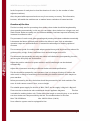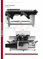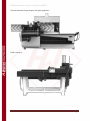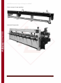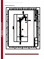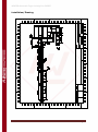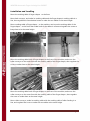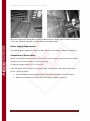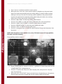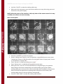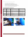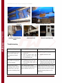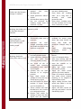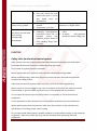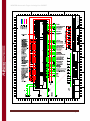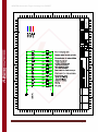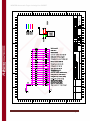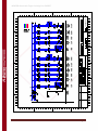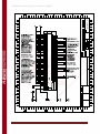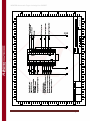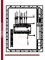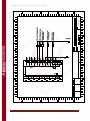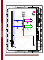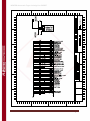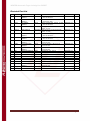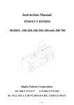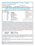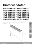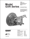
1
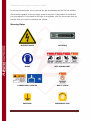
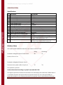
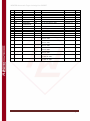
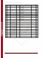
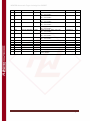
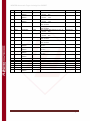
USER MANUAL
WINTER automatische Keilzinkenanlage
Finger Jointing Line Typ EXPERT
Henrik Winter Holztechnik GmbH
Druckereistr. 8
04159 Leipzig
Tel: +49 (0)341/ 4619021 Fax: +49 (0)341/4618358 Funk: +49 (0)171/2820443
Em@il: [email protected] Internet: www.winter-holztechnik.de
WINTER Automatic Finger Jointing Line EXPERT
CONTENTS
Safety Instruction ...................................................................................................................................................... 3
Safety Regulation ................................................................................................................................................. 3
Warning Plates ...................................................................................................................................................... 4
Specification ............................................................................................................................................................... 5
Specification ........................................................................................................................................................... 5
Machine Noise ...................................................................................................................................................... 5
Function of the Line ............................................................................................................................................ 6
Legend of the Machine ...................................................................................................................................... 7
Machine Dimensions ........................................................................................................................................ 10
Installation ................................................................................................................................................................. 11
Safety Rules for Machine Movement ......................................................................................................... 11
Lifting the Machine/Drawing ......................................................................................................................... 11
Selection of Location ........................................................................................................................................ 11
Installation/ Drawing ........................................................................................................................................ 12
Installation and Levelling ................................................................................................................................ 13
Power Supply Requirement............................................................................................................................ 14
Connection of Power Wires ........................................................................................................................... 14
Pneumatic / Power Supply Connection ..................................................................................................... 15
Hydraulic Pressure Supply Connection...................................................................................................... 16
Operation................................................................................................................................................................... 16
Control Panel ....................................................................................................................................................... 16
Emergency Stop.................................................................................................................................................. 19
Adjustment for the Machine/Parts .............................................................................................................. 19
Maintenance ............................................................................................................................................................. 20
Day/Week/Month/Year Maintenance ........................................................................................................ 21
Lubrication ............................................................................................................................................................ 21
Troubleshooting ................................................................................................................................................. 22
Electric ......................................................................................................................................................................... 24
Safety rules for electrical control system .................................................................................................. 24
Electrical Plan ....................................................................................................................................................... 25
Electrical Part List ............................................................................................................................................... 36
Pneumatic/ Hydraulic Plan .................................................................................................................................. 42
Pneumatic ............................................................................................................................................................. 42
Hydraulic ............................................................................................................................................................... 45
Winter Holztechnik GmbH
Page 2
WINTER Automatic Finger Jointing Line EXPERT
SAFETY INSTRUCTION
Any operator must be trained before operating the line, and he must understand the
structure and performance for the line thoroughly.
Before operation, the operator must be familiar with the manual for the line and keep the
safety essentials by heart.
Wear protective clothes before operation and in avoid occurring any accident from running
parts.
This line only can be used within the designed applicable range. It can’t be used overload in
avoid of effecting the useful life for motors and other parts
During operation, it’s strictly forbidden to approach or touch the running parts of the line by
hand without any protection in avoid occurring any accident.
Keep good light for working site, and make sure there are no obstacles to affect the operator.
Don’t leave any tools and material on the line.
Safety Regulation
Make sure there is steady air pressure and power supply. Otherwise, electric appliance
elements might be damaged seriously.
Work object:
This line only be used for process wood material, and it’s not permitted to process any metal
or plastic material by this line.
Depositary:
It’s strictly forbidden to keep this line outdoor and the places with high temperature and
explosive easily.
It’s not allowed to make operation until the complete line has been fixed on the ground.
Before operation, ensure the oil pressure system is in good condition, and the rotary
direction for finger joint cutters and all of saw blades are correct and have been locked
tightly; otherwise, it’s not permitted to operate the line.
During operation, in accord to avoid damage in human body, it’s strictly forbidden to put
your hands on gantry of the conveyor belt, saw blades, cutters and working tables for timber
thrusting.
Winter Holztechnik GmbH
Page 3
WINTER Automatic Finger Jointing Line EXPERT
In case any unusual noise occurs, you stop the line immediately and find out the troubles
Check the air regulator for the air supply system at any time. If the pressure is insufficient,
you must adjust it. It’s consisted of two cups of air regulator, one is to store water from air,
and the other is to add oil to lubricate the cylinder.
Warning Plates
ELECTRIC SHOCK
ROTATION
NOISE
KEEP HANDS AWAY
LUBRICATION / ADD OIL
DON’T TOUCH
EARTHING
EMERGENCY STOP
Winter Holztechnik GmbH
Page 4
WINTER Automatic Finger Jointing Line EXPERT
SPECIFICATION
Specification
SN
1
2
3
4
5
6
7
8
9
10
11
12
13
14
15
Parameter
Table size
Min. working size L*H
Max. working size L*H
Max. working width of table
Cutter spindle diameter
Cutter spindle motor
Cutter spindle speed
Feeding motor
Hydraulic pump power
Drive of hogger and scoring saw
Hogger spindle diameter
Scoring saw spindle diameter
Max. thrust force of working table
Scoring saw specification
Hogger specification
16
Cutter specification
Typ EXPERT
630*800mm
150*20mm
900*150mm
590mm
Ø50mm
15kw
6750rpm
0.75kw
2.2kw
5.5kw
Ø30mm
Ø25.4mm
840kg
Ø110*2.2mm*30T
Cut-off saw: Ø255*Ø50*4.0mm*80T
Hogger: Ø238*Ø30*20mm *12T
Finger Joint Cutter: Ø160*Ø50*4.0mm*2T
Bottom Cutter: Ø160*Ø50*10.0mm*2T
Machine Noise
DECLARED NOISE EMISSION VALUES in accordance with ISO 7960.
Declared A-Weighted Sound Power Level
Idling
Operating
89
91
76
78
Lward, in Db re 1 Pw.
Declared A-Weighted Emission Sound
Pressure Level, 1pAd, in dB re 20 μPa, at
The operator’s position.
Values determined according to specific test code ISO 3746.
The figures quoted are emission levels and are not necessarily safe work levels. Whilst there is
a correlation between emission levels and exposure levels. This can’t be used reliably to
determine whether or not further precautions are required. Factors that influence the actual
Winter Holztechnik GmbH
Page 5
WINTER Automatic Finger Jointing Line EXPERT
level of exposure of work piece in clued the duration of noise (i.e. the number of other
adjacent machines).
Also, the permissible exposure levels can very from country to country. The information,
however, will enable the machine user to make a better evaluation of hazard and risk.
Function of the Line
The line is mainly used for processing short timber, short timber should be lengthened by
glue-spreading automatically, in this way you can make a short timber into a longer one, and
made inferior timber as quality one, the timber availability has been improved efficiently and
increased its utilization value.
The processes of comb-tooth, glue spreading and pressing have been realized automatically.
It decreases the labour efficiently and rectifies the defects in past, such as redundant
operation steps and artificial faults etc. it stressed the advantages of working rapid and
accurate.
The movement guide for working table adopts precise linear guide imported from abroad. Its
guide accuracy is high, friction coefficient is low and with longer service life.
The automatic glue spreading not only can realize well-distributed glue spreading, but also
can save glue and purify the environment.
Adjust the position switches for press machine, and an ideal length can be obtained
automatically.
Adjust the oil pressure according to different timber sorts and specifications.
This line should be operated by two operators. One is in charge of letting off timber; the
other one is in charge of monitoring and controlling the timber condition from shapers to
press machine.
Before processed by this line, the timber should be processed by four-side moulders. The
error of width cannot exceed 1.5mm, so as to height.
The suitable power supply for this line is 380V, 50HZ, and air supply is 6kg/cm2~8kg/cm2.
There must be an electrician who understands electric appliance diagrams.
This line
is suitable for working timber only. Timber with extra-length or extra-big size, or too small or
too short timber can’t be processed by this line. The suitable timber for this line:
Max: 700*150*80mm
Min: 180*30*20mm (L*W*H)
Dust collection system must be equipped for line.
Winter Holztechnik GmbH
Page 6
WINTER Automatic Finger Jointing Line EXPERT
Legend of the Machine
Belt conveyor:
First automatic finger shaper:
Winter Holztechnik GmbH
Page 7
WINTER Automatic Finger Jointing Line EXPERT
Second automatic finger shaper with glue applicator:
Roller conveyor:
Winter Holztechnik GmbH
Page 8
WINTER Automatic Finger Jointing Line EXPERT
Chain conveyor for pre-pressing:
Automatic finger press:
Winter Holztechnik GmbH
Page 9
WINTER Automatic Finger Jointing Line EXPERT
Machine Dimensions
Winter Holztechnik GmbH
Page 10
WINTER Automatic Finger Jointing Line EXPERT
INSTALLATION
Safety Rules for Machine Movement
Pay special attention to carry the machine to avoid occurring any accident, such as: collision,
falling down and intense vibration, which will affect the accuracy of the machine.
Machines need installed in such environment with well ventilation and dry. Also the ground
must be firm and flat. And the machines must be horizontal level and fill up.
Clean all oil foul, impurities and dust before operation after finishing installation.
Connect the main power supply and air supply passages as well as the lighting and
lubrication, etc.
Make sure all moving and running elements are in good condition before connecting the
power and air supplies. Guarantee that the hold-down lock devices are firm and reliable
without any obstacles.
Lifting the Machine/Drawing
When transiting the machine, keep it balance.
Use a forklift with sufficient loading capacity to lift the machine.
Ask another person for help to guide the way when lifting the machine.
The forks of the forklift must protrude from the machine underside.
The forklift must only be driven by an experience forklift drive.
The cushion should be used between metal rope and machine.
Install the base of the machine on the ground, then level the working table.
Selection of Location
Please use the line in the following condition.
Ambience temperature
-10℃~45℃ (no ICE)
Ambience temperature
Below 90% RH (NO DEW)
Depositary temperature
-20℃~+65℃
Environment
Indoor (no causticity gas, combustible gas, oil gas etc.)
Altitude
Below 1000m
Winter Holztechnik GmbH
Page 11
WINTER Automatic Finger Jointing Line EXPERT
Installation/ Drawing
Winter Holztechnik GmbH
Page 12
WINTER Automatic Finger Jointing Line EXPERT
Installation and Levelling
Move the working table of finger shaper to the front.
Move belt conveyor, and make its working table and the finger shaper’s working table in a
line, then regulate the foundational screw to make the two tables in the same height.
Move working table of finger shaper to the machine, and move the working table of the
finger shaper to the front then make both of the tables in a line and regulate the screw to
keep them at in the same height.
Move the working table both of finger shaper to the front of the machine, and move the
roller conveyor to the same line with the working table of the finger shaper, then regulate the
screw to make them at the same height.
Move the working table both of finger shaper to the front of the machine, and move the
roller conveyor to the same line with the working table of the finger shaper , then regulate
the screw to make them at the same height.
Move chain conveyor, make its working table with the working table of roller feeding in a
line, and regulate the screw to make the two tables at the same height.
Winter Holztechnik GmbH
Page 13
WINTER Automatic Finger Jointing Line EXPERT
Move the finger press and make its working table with the working table of chain conveyor in
a line, then regulate the screw to make them at the same height.
Power Supply Requirement
The suitable power supply for this line is 380V, 50HZ, and air supply is 6kg/cm2~8kg/cm2.
Connection of Power Wires
Before connecting the power wires to your factory power supply, reconfirm that the voltage
of the line is the same as that of your power supply.
Connect the power wires to L1, L2, L3 and PE.
After the power wires have been connected, make sure they are connected to the correct
points. Shown as follow:
•
The line should be properly grounded to prevent the danger of electrical shock.
•
All electrical connections should be performed by qualified operators.
Winter Holztechnik GmbH
Page 14
WINTER Automatic Finger Jointing Line EXPERT
?12
?10
?12
?12
11
?10
Pneumatic / Power Supply Connection
Winter Holztechnik GmbH
Page 15
WINTER Automatic Finger Jointing Line EXPERT
Hydraulic Pressure Supply Connection
OPERATION
Control Panel
Finger shaper-station (first and second)
Winter Holztechnik GmbH
Page 16
WINTER Automatic Finger Jointing Line EXPERT
•
Press “source” to make the machine connect power.
•
When press the “auto. Run” button and the button is brighten up, the press board
clamp the timber automatically and the working tables go forward. When working
table get to the tip of the rail, the inducing switch installed on the pressure board
receives the signal and the material-pushing board will push timber, then working
tables return to the start position automatically.
•
Press the “FWD TABLE” to make the working table forward.
•
Press the “FEV TABLE” to make the working table back off to the start position.
•
Press the “PANEL-HOLD-DOWN” to make the panel clamp the timber.
•
Press the “RELEASE WORK” to make the panel release the timber.
•
Press the “STOP” to make the moving parts stop.
•
Press the “emergency stop” to make the whole machine to stop and disconnect from
the power.
NOTE: after the power of the machine is on, only if all motor must be in stop position,
the motor can start normally.
Finger jointing machine-station 3
•
Rotate “POWER SWITCH” button to the ON ( I ) position to connect the power and the
“POWER INDICTOR” is brightening up.
•
Press the “oil pump start” button to make oil pump start, and press the “oil pump
stop” oil pump stop.
•
When press the “AUTO START” button and the button is brightening up, the pressure
boards clamp the timber automatically and the working table goes forward.
Winter Holztechnik GmbH
Page 17
WINTER Automatic Finger Jointing Line EXPERT
•
Hold the “PAUSE” to make the working table stop.
•
When press the emergency stop, the whole machine must stop all moving parts and
disconnect with power supply.
NOTE: After the power of the machine is ON, only when all the motors must be in stop
condition, the motors can start normally.
Main control panel
•
Press the “SOURCE” to connect the power.
•
Rotate “milling cutter” button to the ON position, cutter spindle motor start; rotate
“butting saw” button to the ON position, the saw start; rotate “oil pump start” button
to ON position, oil pump start.
•
Press “top saw” to make top saw motor to start.
•
Press “bottom saw” to make bottom scoring saw motor start.
•
When press the “auto run” button and the button is brightening up, the pressure
board clamps the timber automatically and working table goes forward. When
working table gets to the tip of the rail, the inducing switch installed on the pressure
board received the signal and the pushing board will push out the timber, their
working table return to the start position automatically.
•
Press the “FWD TABLE” to make the working table forward.
Winter Holztechnik GmbH
Page 18
WINTER Automatic Finger Jointing Line EXPERT
•
Press the “FEV TABLE” to make the working table back off to the start.
•
Press the “PANEL-HOLD-DOWN” to make the panel clamp the timber.
•
Press the “RELESE WORK” to make the panel release the timber.
•
Press the “stop” to make the moving parts stop.
•
Press the “emergency stop” to make the whole machine to stop and disconnect from
the power.
NOTE: After the power of the machine is on, only if all motors must be in stop position,
the motor can start normally.
Emergency Stop
Emergency stop is located on following locations:
•
Station 1
•
Station 2
•
Station 1&2
•
Finger jointing assembler-station3
•
Finger joint system
•
Chain conveyor
Function it to cut off the power and make the machines stop.
The total numbers of emergency stop are 10 pieces.
Adjustment for the Machine/Parts
Adjustment for conveyor belt
It consists of table, rotating roller, motor, chain, conveyor belt, adjust screws etc. if conveyor
belt moves towards left or right, adjust the screws at two sides of roller until the conveyor
belt fixed in the middle of table..
Adjustment for hogger (butting saw)
It consists of motor, saw blade, moving drag board, lead screw, inlaid strip and screws etc. if
the length of teeth of timber is too long or too short, loosen the inlaid strip screws and adjust
the adjusting lead screw by hand wheel to make the drag board forward or backward accord
with the requirements
The adjustment method for top scoring saw and bottom scoring saw are the same as
hogger’s. Mainly as long as adjust top scoring saw and bottom scoring saw to 90°to hogger.
Winter Holztechnik GmbH
Page 19
WINTER Automatic Finger Jointing Line EXPERT
Adjustment for cutter spindle
It consists of spindle, internal and outer sleeves, lift/lower hand wheel, locking screw, and
motor, motor base, fix screw, adjusting screw etc. if the finger joints uneven for its top and
bottom surfaces, loosen the locking screws of the outer sleeve and turn the lift/lower hand
wheel, rise or descend the spindle until the finger joints smoothly and neatly. Then, lock the
outer sleeve screw. If the belt for spindle is too loose, loosens the fix screw of motor base,
adjust screws with wrench, move motor forward or backward to tense or loosen the belt.
After adjustment, lock the fix screws. (When belt slides you can coat some belt glue on
contact surface of it)
Adjustment for guide retainer for gantry frame
Guide retainer is close relation with the angle of the finger of timber. If any error occurs,
loosen the top and bottom fix screws on guide
retainer of the gantry frame, and adjust
the guide retainer according to the angle error direction.
Ultra- pressure protection setting for oil pressure system
According to the pressure relay index to adjust the rated pressure close to 150kg/cm2, and
then start the oil pump. In the middle of manual, press down oil pressure button, adjust
pressure valve and make the oil pressure is just up to 150kg/cm2 to stop machine for
protection. (it has been set to 150kg/cm2 when it is sent out of our factory)
Adjustment of cylinder pressure
During operation, the normal pressure should be 6kg/cm2~8kg/cm2, if the pressure is too
low, turn the pressure-adjusting knob on air regulator until it is up to normal pressure.(The
pressure has been set to 6kg/cm2 when the machine is sent out of our factory)
Adjustment for side panel-hold-down for working table
When side panel-hold-down is un-smoothly, you should adjust the rolling bearing for the
working table or check the air passage whether there are some troubles for two double
directional guiding valves. If yes, adjust or replacement.
Adjustment for conveyor belt
If the conveyor belt is too loose or too tense, it should adjust the screws at both sides of
conveyor belt wheel.
MAINTENANCE
Everyday check of the safety system before machine start:
Winter Holztechnik GmbH
Page 20
WINTER Automatic Finger Jointing Line EXPERT
•
The emergency stops are available or not.
•
The joint of hydraulic does have leakage of oil or not.
•
The lubricating oil of air regulators are enough or not.
•
The screw of the frequently moving parts is loosened or not.
•
The nuts of pneumatic cylinders are fastened or not.
Day/Week/Month/Year Maintenance
Periodic
add oil
position
Method
Type
Every day
Linear guide
block
Guide oil ( SH/T03611992)
Every day
Bearing of
cutter spindle
Every day
Bearing of
linear guide
Every day
Chain, gear
Press the handle of the lubricating
oil pump
Use oil gum to make the
lubricating grease inject the hole of
spindle
Make the lubricating oil spreading
the guide directly
Make lubricating oil spreading the
gear or chair
Lubricating grease of
machine tool spindle
Normal gear oil (
SH/T0363-1992)
Normal gear oil
(SH/T0363-1992)
Lubrication
MXB3515B-A/MXB3515B-B conveyor belt
Winter Holztechnik GmbH
RC2X800 transmission chain
Page 21
WINTER Automatic Finger Jointing Line EXPERT
SC3000 Fluctuation wheel of feeding
machine
MHB1560B-C
Feeding material press
wheel
SC3000 moving haul board
Side board rack
Material-pushing rack
Troubleshooting
Trouble
Cause
Power supply indicating
1. Power supply hasn’t been 1. switch on power supply switch
switch on.
2. One or more fuse FU1, 2. replace the burnt fuse
FU2, FU3.FU4, FU5, FU6,
FU7 has been out.
lamp doesn’t light up,
and machine doesn’t
start.
Working start indicating
lamp flash and machine
can’t be started.
Resolving method
1. Air pressure is insufficient. 1. Increase air pressure.
2. Overload protection FR1~ 2. press down reset button FR1
~FR9 by hand and make the
FR9 among them one or
more act.
working thermal relay reset
In the mode of auto.
CK1 release panel check
Adjust the position for CK1 and
Working, motor can be
occurs shift and signal has not
make CK1 just can check out the
started, but it can’t get
been checked out by CK1.
signal under the state of release
into auto. Working state.
panel(indicating lamp on CK1
lights up)
Winter Holztechnik GmbH
Page 22
WINTER Automatic Finger Jointing Line EXPERT
In the mode of auto.
1. C machine has not
entered
into
auto.
Working start.
2. check protection without
timber
3. this machine memory feed
has not received the
working signal from B
machine “ to clear”
F machine has not been
Working, the timber can’t
started to work
In the mode of auto.
Timber can’t be fed pass
through C machine.
1. Start B machine and enter
into auto. Working start
2. Press down the “working
start” for a long time (2
seconds)
and
make
protective reset.
3. Press down “working start”
for this machine for a long
time (2 seconds) to clear.
Start F machine to work
be fed pass through C
machine
Power supply indicating
lamp (finger joint
machine) lights up, but
can’t enter into any
working mode.
In the mode of auto.
Working, feed holddown roller doesn’t work.
Winter Holztechnik GmbH
1. Overload protection FR1~ 1. Eliminate the cause of
overload for motor, press
FR8 among them one or
down the reset button by
more act.
hand,
and
make
the
2. misadjust
the
ultraprotective thermal relay re
voltage protection switch
set.
and make the check of the
2. Reset
ultra-voltage
machine occurs error
protection
switch
to
2
150kg/cm
1. Working start button has 1. press down working start
not been pressed down.
button
2. timber has been clamped 2. move off clamped timber
and can’t enter into 3. After stop running, take off
trimming check position
the timber with too much oil.
3. too much oil dirt on 4. reset the cylinder to its
timber
and
trimming
original position
photoelectric can’t check 5. adjust the check switch
out its signal
position for cylinder
4. cylinder has not been 6. adjust the check switch
retraced to its original
position for thrust retainer
position
7. Clean off unusual substance
5. reset check switch of
and make thrust retainer
cylinder is loose and can’t
retracing to its original to
check out any signal
induced limit switch.
6. rear limit switch for thrust 8. adjust sawing bottom limit
retainer is loose, signal
switch and make it can be
can’t be checked out
checked by signal
7. Thrust retainer has been 9. adjust real limit switch for
blocked and can’t retrace
side clip and make it can be
checked by signal
to its original position.
8. Bottom limit switch for
sawing is loose and limit
signal can’t be checked
Page 23
WINTER Automatic Finger Jointing Line EXPERT
9.
Jointed timber can’t be
thrust out by cylinder
Once cylinder hold-down
the timber and machine
stop running
automatically
immediately
1.
2.
1.
2.
out.
rear limit switch for side
panel-hold-down is loose
and signal can’t be
checked out
Oil pump has not been
started.
oil pressure is too low
Oil pressure is too high
misadjust extra-pressure
protection switch for oil
pressure
system
and
machine protect ahead of
time reaching finger joint
pressure
Start the oil pump. Adjust oil
pressure to a higher value.
1. adjust oil pressure to a lower
value
2. re-adjust
extra-pressure
protection switch 150kg /cm2
ELECTRIC
Safety rules for electrical control system
Only operator who are properly trained and have adequate knowledge and skill should
undertake all electrical. Electronic troubles shooting and repair.
Do not alter or bypass protective interlocks
Before operate this line, operators must read and observe all warning labels.
When trouble shooting, make sure the power source has been disconnected and main
switches have been locked.
Take extra precautions in damp areas to protect you from accidental grounding.
Before switch on power supply for any unit of machines for this line, the machine must be
fixed steadily on ground. Make sure there are no other people near the machine.
Do not open the electrical control panel unless it is necessary to check the electrical
equipment.
It’s not permitted to alter the electrical circuits without authorized by the manufacture.
When replacing electrical components, make sure they conform to the manufacture’s
specifications, including proper colour coding.
Do not wear metal frame glasses, metallic necklaces or chains while working on any electrical
equipment. Also do not wear any ring, watch or bracelet while operating electrical
equipment.
Winter Holztechnik GmbH
Page 24
WINTER Automatic Finger Jointing Line EXPERT
Electrical Plan
Winter Holztechnik GmbH
Page 25
20060401-2
WINTER Automatic Finger Jointing Line EXPERT
Winter Holztechnik GmbH
Page 26
20060401-3
WINTER Automatic Finger Jointing Line EXPERT
Winter Holztechnik GmbH
Page 27
20060401-4
WINTER Automatic Finger Jointing Line EXPERT
Winter Holztechnik GmbH
Page 28
20060401-5
WINTER Automatic Finger Jointing Line EXPERT
Winter Holztechnik GmbH
Page 29
20060401-6/1
WINTER Automatic Finger Jointing Line EXPERT
Winter Holztechnik GmbH
Page 30
20060401-6/2
WINTER Automatic Finger Jointing Line EXPERT
Winter Holztechnik GmbH
Page 31
Over-road protection for motor
20060401-6/3
WINTER Automatic Finger Jointing Line EXPERT
Winter Holztechnik GmbH
Page 32
20060401-6/4
WINTER Automatic Finger Jointing Line EXPERT
Winter Holztechnik GmbH
Page 33
20060401-7
WINTER Automatic Finger Jointing Line EXPERT
Winter Holztechnik GmbH
Page 34
0
220V
AC
L19
20060401-8
WINTER Automatic Finger Jointing Line EXPERT
Winter Holztechnik GmbH
Page 35
WINTER Automatic Finger Jointing Line EXPERT
Electrical Part List
SN
1
SYNBOL
PPS1
MAKER
SICK
KM1
NAME
PROXIMITY
SWITCH
PROXIMITY
SWITCH
PROXIMITY
SWITCH
REED SWITCH
2
PPS2
3
PPS3
4
5
KM2-9
REED SWITCH
NORGEN
6
PRS4
SICK
7
PRS5
8
PHS1
9
PHS2
10
PHS3
11
12
13
14
15
16
17
18
SP1
SB6
SB7
SB8
SB9
SB10
SB11
PHS4
19
20
SB15
SB16
PROXIMITY
SWITCH
PROXIMITY
SWITCH
PHOTOELECTRIC
SWITCH
PHOTOELECTRIC
SWITCH
PHOTOELECTRIC
SWITCH
PRESSURE SWITCH
PUSH BUTTONS
PUSH BUTTONS
PUSH BUTTONS
PUSH BUTTONS
PUSH BUTTONS
SELECTOR SWITCH
PHOTOELECTRIC
SWITCH
SELECTOR SWITCH
Winter Holztechnik GmbH
SICK
SICK
NORGEN
SICK
SICK
SICK
SICK
SMC
APT
APT
APT
APT
APT
APT
SICK
APT
SPECIFICATION
IM12-04NNS-ZW1 300mA 10-30V
-25℃ TO DC 70℃
IM12-04NNS-ZW1 300mA 10-30V
-25℃TO DC 70℃
IM12-04NNS-ZW1 300mA 10-30V
-25℃ TO DC 70℃
M150/LSU/2V 0.18A AC24 10W 20℃ TO 80℃
M150/LSU/2V 0.18A AC24 10W 20℃ TO 80℃
IM12-04NNS-ZW1 300mA 10-30V
-25℃ TO DC 70℃
IM12-04NNS-ZW1 300mA 10-30V
-25℃ TO DC 70℃
WT100-N1439 0.1A DC10-30 25℃ TO 55℃
WT100-N1439 0.1A DC10-30 25℃ TO 55℃
WT100-N1439 0.1A DC10-30 25℃ TO 55℃
IS3000-02 4A 30V DC
LA39 10A 660V AC 10W
LA39 10A 660V AC 10W
LA39 10A 660V AC 10W
LA39 10A 660V AC 10W
LA39 10A 660V AC 10W
LA39 10A 660V AC 10W
WT100-N1439 0.1A DC10-30 25℃ TO 55℃
LA39 10A 660V AC 10W
STANDARD
EN80947-4-1
APP
CE
EN80947-4-1
CE
EN80947-4-1
CE
EN80947-4-1
CE
EN80947-4-1
CE
EN80947-4-1
CE
EN80947-4-1
CE
EN80947-4-1
CE
EN80947-4-1
CE
EN80947-4-1
CE
EN80947-4-1
EN80947-4-1
EN60947-5-1
EN60947-5-1
EN60947-5-1
EN60947-5-1
EN60947-5-1
EN60947-5-1
CE
CE
CE
CE
CE
CE
CE
CE
EN60947-5-1
EN60947-5-1
CE
CE
Page 36
WINTER Automatic Finger Jointing Line EXPERT
SN
1
2
3
4
5
6
7
SYNBOL
KA1-6
KA7-21
KA22-23
KA24
KA25
KA26-27
KM1
MAKER
IDCC
IDCC
IDCC
IDCC
IDCC
FUJI
FUJI
SPECIFICATION
RY4S-U 5A 240V AC
RY4S-U 5A 240V AC
RY4S-U 5A 240V AC
RY4S-U 5A 240V AC
RY4S-U 5A 240V AC
RY4S-U 5A 240V AC
SC-03 20A 380V AC 4KW
STANDARD
IE255
IE255
IE255
IE255
IE255
IE255
EN60947-4-1
APP
CE
CE
CE
CE
CE
CE
CE
KM2
KM3
KM4
KM5
KM6
KM7
YV4
NAME
REED RELAY
REED RELAY
REED RELAY
REED RELAY
REED RELAY
REED RELAY
MAGNETIC
CONTACTOR
MAGNETIC
MAGNETIC
MAGNETIC
MAGNETIC
MAGNETIC
MAGNETIC
VALVE
8
9
10
11
12
13
14
FUJI
FUJI
FUJI
FUJI
FUJI
FUJI
NORGEN
SC-03 20A 380V AC 4KW
EN60947-4-1
EN60947-4-1
EN60947-4-1
EN60947-4-1
EN60947-4-1
EN60947-4-1
EN12266-2
CE
CE
CE
CE
CE
CE
CE
15
YV5
VALVE
NORGEN
EN12266-2
CE
16
YV6
VALVE
NORGEN
EN12266-2
CE
17
YV7
VALVE
NORGEN
EN12266-2
CE
18
YV8
VALVE
NORGEN
EN12266-2
CE
19
YV9
VALVE
NORGEN
EN12266-2
CE
20
YV10
VALVE
NORGEN
EN12266-2
CE
Winter Holztechnik GmbH
SC-03 20A 380V AC 4KW
SC-03 20A 380V AC 4KW
SC-03 20A 380V AC 4KW
SC-03 20A 380V AC 4KW
V61B513A-A2 10-24V -20℃ TO
80℃ AC 10W
V61B513A-A2 10-24V -20℃ TO
80℃ AC 10W
V61B511A-A3 10-240V -20℃ TO
80℃ AC 10W
V61B511A-A3 10-240V -20℃ TO
80℃ AC 10W
V61B511A-A3 10-240V -20℃ TO
80℃ AC 10W
V62B511A-A3194 10-240V -20℃
TO 80℃ AC 10W
V62B511A-A3194 10-240V -20℃
TO 80℃ AC 10W
Page 37
WINTER Automatic Finger Jointing Line EXPERT
SN
1
SYNBOL
YV11
NAME
VALVE
MAKER
NORGEN
2
YV13
VALVE
NORGEN
3
YV14
VALVE
NORGEN
4
YV15
VALVE
NORGEN
5
YV16
VALVE
NORGEN
6
7
8
YV17
YV18
YV19
VALVE
VALVE
VALVE
KINGST
KINGST
NORGEN
9
YV20
VALVE
NORGEN
10
YV21
VALVE
NORGEN
11
FR1
12
FR2
13
FR3
14
FR4
15
FR5
16
FR6
17
FR7
18
FR8
19
FR9
20
SB15.115.6
THREMAL
OVERLOAD RELAY
THREMAL
OVERLOAD RELAY
THREMAL
OVERLOAD RELAY
THREMAL
OVERLOAD RELAY
THREMAL
OVERLOAD RELAY
THREMAL
OVERLOAD RELAY
THREMAL
OVERLOAD RELAY
THREMAL
OVERLOAD RELAY
THREMAL
OVERLOAD RELAY
PUSH BUTTONS
Winter Holztechnik GmbH
STANDARD
EN12266-2
APP
CE
EN12266-2
CE
EN12266-2
CE
EN12266-2
CE
EN12266-2
CE
EN12266-2
EN12266-2
EN12266-2
CE
CE
CE
EN12266-2
CE
EN12266-2
CE
FUJI
SPECIFICATION
V62B511A-A3194 10-240V -20℃ TO
80℃ AC 10W
V62B511A-A3194 10-240V -20℃ TO
80℃ AC 10W
V61B511A-A3 10-240V -20℃ TO
80℃ AC 10W
V61B511A-A3 10-240V -20℃ TO
80℃ AC 10W
V61B511A-A3 10-240V -20℃ TO
80℃ AC 10W
DSG-3C4-N-02-A25 220V AC
DSG-3C4-N-02-A25 220V AC
V61B511A-A3 10-240V -20℃ TO
80℃ AC 10W
V61B511A-A3 10-240V -20℃ TO
80℃ AC 10W
V61B511A-A3 10-240V -20℃ TO
80℃ AC 10W
TR-ON/3 6-9A 380V AC
EN80947-4-1
CE
FUJI
TR-ON/3 6-9A 380V AC
EN80947-4-1
CE
FUJI
TR-ON/3
1.7-2.6A
240V AC
EN80947-4-1
CE
FUJI
TR-ON/3
1.7-2.6A
240V AC
EN80947-4-1
CE
FUJI
TR-ON/3
1.7-2.6A
240V AC
EN80947-4-1
CE
FUJI
TR-ON/3
1.7-2.6A
240V AC
EN80947-4-1
CE
FUJI
TR-ON/3
2.8-4.2A 240V AC
EN80947-4-1
CE
FUJI
TR-ON/3
1.7-2.6A
240V AC
EN80947-4-1
CE
FUJI
TR-ON/3
1.7-2.6A
240V AC
EN80947-4-1
CE
APT
LA39 10A 660V AC 10W
EN80947-4-1
CE
Page 38
WINTER Automatic Finger Jointing Line EXPERT
SN
1
SYNBOL
QF1
NAME
CIRCUIT-BREAKER
MAKER
CHNT
2
QF2
CIRCUIT-BREAKER
CHNT
3
QF3
CIRCUIT-BREAKER
CHNT
4
QF4
CIRCUIT-BREAKER
CHNT
5
QF5
CIRCUIT-BREAKER
CHNT
6
QF6
CIRCUIT-BREAKER
CHNT
7
QF7
CIRCUIT-BREAKER
CHNT
8
QF8
CIRCUIT-BREAKER
CHNT
9
10
11
12
13
14
15
TC
HL1
HL2
HL3
HL4
EV
GS
REED SWITCH
RED
RED
RED
RED
COOL FAN
POWER SUPPLY
TENGEN
APT
APT
APT
APT
SUNON
OMRON
Winter Holztechnik GmbH
SPECIFICATION
DZ47-60 C60 60A 400V 0.75-0.8A
AC -5℃ TO 40℃
DZ47-60 C60 60A 400V 0.75-0.8A
AC -5℃ TO 40℃
DZ47-60 C60 60A 400V 0.75-0.8A
AC -5℃ TO 40℃
DZ47-60 C3 3A 400V 0.65-0.7A
AC -5℃ TO 40℃
DZ47-60 C3 3A 400V 0.65-0.7A
AC -5℃ TO 40℃
DZ47-60 C3 3A 400V 0.65-0.7A
AC -5℃ TO 40℃
DZ47-60 C3 3A 400V 0.65-0.7A
AC -5℃ TO 40℃
DZ47-60 C3 3A 400V 0.65-0.7A
AC -5℃ TO 40℃
BK300 180mA 380V AC
AD16-22D/S 20mA 380V AC 10W
AD16-22D/S 20mA 380V AC 10W
AD16-22D/S 20mA 380V AC 10W
AD16-22D/S 20mA 380V AC 10W
220-240V 50/60HZ 0.14A
S8JC-05024 1.0A 185-264V AC 50W
-25℃ TO 65℃
STANDARD
EN60947-2
APP
CE
EN60947-2
CE
EN60947-2
CE
EN60947-2
CE
EN60947-2
CE
EN60947-2
CE
EN60947-2
CE
EN60947-2
CE
EN60747
EN60947-4-1
EN60947-4-1
EN60947-4-1
EN60947-4-1
EN60947-4-1
EN60947-4-1
CE
CE
CE
CE
CE
CE
CE
Page 39
WINTER Automatic Finger Jointing Line EXPERT
SN
1
SYNBOL
PRS1
MAKER
SICK
KM1
NAME
PROXIMITY
SWITCH
PROXIMITY
SWITCH
PROXIMITY
SWITCH
REED SWITCH
2
PRS2
3
PRS3
4
5
KM2-9
REED SWITCH
NORGEN
6
PRS4
PROXIMITY
SICK
7
PRS5
PROXIMITY
SICK
8
KM11
REED SWITCH
NORGEN
9
KM12
REED SWITCH
NORGEN
10
PHS1
SICK
11
PHS2
12
PKS3
13
SP1
14
15
16
17
18
19
20
SP2
SB6
SB7
SB8
SB9
SB10
SB11
PHOTOELECTRIC
SWITCH
PHOTOELECTRIC
SWITCH
PHOTOELECTRIC
SWITCH
PRESSURE
SWITCH
VALVE
PUSH BUTTONS
PUSH BUTTONS
PUSH BUTTONS
PUSH BUTTONS
PUSH BUTTONS
SELECTOR
SWITCH
Winter Holztechnik GmbH
STANDARD
EN60947-4-1
APP
CE
EN60947-4-1
CE
EN60947-4-1
CE
EN60947-4-1
CE
EN60947-4-1
CE
EN60947-4-1
CE
EN60947-4-1
CE
EN60947-4-1
CE
EN60947-4-1
CE
EN60947-4-1
CE
EN60947-4-1
CE
EN60947-4-1
CE
SMC
SPECIFICATION
IM12-04NNS-ZW1 300mA 10-30V -25
℃ TO DC 70℃
IM12-04NNS-ZW1 300Ma 10-30V -25
℃ TO DC
70℃
IM12-04NNS-ZW1 300Ma 10-30V -25
℃ TO DC
70℃
M150/LSU/2V 0.18A AC24 10 W
-20℃ TO 80℃
M150/LSU/2V 0.18A AC24 10 W
-20℃ TO 80℃
IM12-04NNS-ZW1 300mA 10-30V -25
℃ TO DC 70℃
IM12-04NNS-ZW1 300mA 10-30V -25
℃ TO DC 70℃
M150/LSU/2V 0.18A AC24 10 W
-20℃ TO 80℃
M150/LSU/2V 0.18A AC24 10 W
-20℃ TO 80℃
WT100-N1439 0.1A DC 10-30 -25℃
TO 55℃
WT100-N1439 0.1A DC 10-30 -25℃
TO 55℃
WT100-N1439 0.1A DC 10-30 -25℃
TO 55℃
IS3000-02
4A 30V DC
EN60947-5-1
CE
KINGST
APT
APT
APT
APT
APT
APT
JCS-02
LA39
LA39
LA39
LA39
LA39
LA39
EN60947-5-1
EN60947-5-1
EN60947-5-1
EN60947-5-1
EN60947-5-1
EN60947-5-1
EN60947-5-1
CE
CE
CE
CE
CE
CE
CE
SICK
SICK
NORGEN
SICK
SICK
3A
10A
10A
10A
10A
10A
10A
250V AC
660V AC
660V AC
660V AC
660V AC
660V AC
660V AC
10W
10W
10W
10W
10W
10W
Page 40
WINTER Automatic Finger Jointing Line EXPERT
SN
1
2
3
4
5
6
7
SYNBOL
KA1-5
KA10-21
KA22-23
KA24
KA25
KA26-27
KM1
MAKER
IDCC
IDCC
IDCC
IDCC
IDCC
IDCC
FUJI
SPECIFICATION
RY4S-U
5A
240V AC
RY4S-U
5A
24V AC
RY4S-U
5A
240V AC
RY4S-U
5A
24V AC
RY4S-U
5A
240V AC
RY4S-U
5A
24V AC
SC-03
20A 380V AC 4KW
STANDARD
EN60947-4-1
EN60947-4-1
EN60947-4-1
EN60947-4-1
EN60947-4-1
EN60947-4-1
EN60947-5-1
APP
CE
CE
CE
CE
CE
CE
CE
FUJI
SC-03
20A 380V AC
4KW
EN60947-5-1
CE
FUJI
SC-03
20A 380V AC
4KW
EN60947-5-1
CE
FUJI
SC-03
20A 380V AC
4KW
EN60947-5-1
CE
FUJI
SC-03
20A 380V AC
4KW
EN60947-5-1
CE
FUJI
SC-03
20A 380V AC
4KW
EN60947-5-1
CE
FUJI
SC-03
20A 380V AC
4KW
EN60947-5-1
CE
Y4
NAME
REED RELAY
REED RELAY
REED RELAY
REED RELAY
REED RELAY
REED RELAY
MAGNETIC
CONTACTOR
MAGNETIC
CONTACTOR
MAGNETIC
CONTACTOR
MAGNETIC
CONTACTOR
MAGNETIC
CONTACTOR
MAGNETIC
CONTACTOR
MAGNETIC
CONTACTOR
VALVE
8
KM2
9
KM3
10
KM4
11
KM5
12
KM6
13
KM7
14
NORGEN
EN60947-5-1
CE
15
Y5
VALVE
NORGEN
EN60947-5-1
CE
16
Y6
VALVE
NORGEN
EN60947-5-1
CE
17
Y7
VALVE
NORGEN
EN60947-5-1
CE
18
Y8
VALVE
NORGEN
EN60947-5-1
CE
19
Y9
VALVE
NORGEN
EN60947-5-1
CE
20
Y10
VALVE
NORGEN
V61B513A-A2 10-24V -20℃ TO
80℃ AC
10W
V61B513A-A2 10-24V -20℃ TO
80℃ AC
10W
V61B511A-A3 10-240V -20℃ TO
80℃ AC
10W
V61B511A-A3 10-240V -20℃ TO
80℃ AC
10W
V61B511A-A3 10-240V -20℃ TO
80℃ AC
10W
V62B511A-A3194 10-240V -20℃ TO
80℃ AC
10W
V62B511A-A3194 10-240V -20℃ TO
80℃ AC
10W
EN60947-5-1
CE
Winter Holztechnik GmbH
Page 41
WINTER Automatic Finger Jointing Line EXPERT
PNEUMATIC/ HYDRAULIC PLAN
100
45
20051115-2
Pneumatic
Winter Holztechnik GmbH
Page 42
100
50 250
70
20051115-3
WINTER Automatic Finger Jointing Line EXPERT
Winter Holztechnik GmbH
Page 43
Winter Holztechnik GmbH
40
63
63
63
63
40
50
130
230
20051115-1
WINTER Automatic Finger Jointing Line EXPERT
Page 44
WINTER Automatic Finger Jointing Line EXPERT
.1
20060329-1
Hydraulic
Winter Holztechnik GmbH
Page 45
.1
20060329-2
WINTER Automatic Finger Jointing Line EXPERT
Winter Holztechnik GmbH
Page 46