1
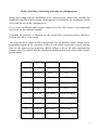
XS 2000 HT User Manual
INDEX
Before the installation
Introduction to the use
pag. 3
pag. 4
1 Remote control functions
2 Input panel and keys
3 Connections inputs
- Possibilities of connection to the VGA input
4 Adjustment via remote control and control rear panel
5 Banks memorizations
- Guide: how to use the bank
- Pre-memorization (factory pre-set)
- Example of personalization
- Chart of the prememorized banks
6 List of the menu regulations
7 Menu ADJUSTMENT
- Brightness, Contrast, Color, Hue, Black Plus, Gamma
8 Menu QUALITY
- Peaking, CTI, NTSC matrix
9 Menu WHITE BALANCE
- R G B dark , R G B bright
10 Menu SERVICE
- Cut-off
- White peak
- W. P. Mode
- B Plus
- Language
11 Menu SOURCE
- Input Select, Standard, Comb Filter, VCR/TV
12 Menu SIZE ADJ.
- V. size, H.size, H. fase, Keystone, Pincushion
13 Menu CONVERGENCE
- SHIFT R G B é ê R G B ç è
- Corner Adjust, Blanking Top Left Right
14 Test: internal crosshatch
15 Function of key "A" of the remote control
(invert keystone V)
16 Function of key "B" of the remote control
(non standard VGA versions)
pag. 5
pag. 6
pag. 7
pag. 9
pag. 11
pag. 14
pag. 15
pag. 17
pag. 18
pag. 18
pag. 19
pag. 20
pag. 22
pag. 22
pag. 24
pag. 25
pag. 25
2
Before installing, connecting and using the videoprojector
Before proceeding with the installation of the videoprojector, please read carefully the
handbooks supplied which contain all information you need for the installation, initial
set-up and the use of the videoprojector.
For a correct installation and a proper connection of the video sources, we recommend
you to ask for the technical support.
Originally the projector is adjusted for the frontal floor projection and by default it
projects on a 2m x 1.5m screen.
The projector has a initial default configuration for the memory banks, which can be
programmed again as the customer wishes to, and which represents a goods starting
base for the initial set-up operations. Below follows a list of all main configuration
features saved by default and the installation handbook describes some further details
on this matter.
KEY
INPUT
STANDARD
FORMAT
1
VIDEO1
PAL
4:3
2
VIDEO2
PAL
4:3
3
S-VHS
PAL
4:3
4
VIDEO1
PAL
16:9
5
S-VHS
PAL
16:9
6
VGA IN
640 x 480
VGA 31.5 KHZ
7
VGA IN
800 x 600
VESA 36 KHZ
8
VGA IN
1024 x 768
XGA 35.5KHZ
9
VGA IN
640 x 480
CUSTOM
0
VIDEO1
TEST
3
INTRODUCTION TO THE USE OF THE VIDEOPROJECTOR
The commands of the XS 2000 HT are designed for using the videoprojector in the
easiest and the most straightforward way possible, still maintaining the possibility of
acting on all parameters, also the specifically technical ones, by means of a infrared
remote-control.
After having correctly performed the installation and the initial set-up, the user can
display the image as he wishes, optimally adjusting it by simply pressing one of the
selection buttons from 0..to 9 on the remote control.
During the initial adjustment each one of the 10 buttons is matched, by saving, to the
video source and its wide range of functions and adjustments.
The user may save a new condition or retrieve the last one he saved for each button
any time he likes.
From the remote control the user may also adjust the Brightness, Colour, Contrast and
the Chroma control (for the NTSC standards).
The operations for selecting the inputs, the standards, the options, and to fix the
dimensions and the quality of the image may be performed directly from the remote
control and can be reached by scrolling the menu options displayed (OSD).
When pressing any of the four “arrow” buttons, the menu is made active on the screen
With the é and ê buttons you can select the option or the "SUB-MENU" you wish.
With the ç and è buttons you may change the function you wish.
The "OSD" disappears automatically after about 10 seconds from the last operation.
A control panel on the projector grants the possibility of controlling the projector in
case the remote control is not working (batteries empty).
To modify or add the configurations, you may temporarily or permanently change the
options and the adjustments, read the rest in this handbook, which describes all
possible operations and adjustments in detail.
4
// Activate test signal in service mode
1. THE REMOTE CONTROL
Control and Functions
12.- VGA 1. - Stand-by / On//- On su bank R
2. - Memory
3. - Enter menu - Move menu cursor down ê
4. - Quit menu ç - Decrease selected function
5. - Enter menu è - Increase selected function
6. - Move menu cursor up é
7. - Recall memory bank
8. - Switch off OSD
9. - **//Force autosync
10.-**// Invert TRV
11.- Activate test signal select button
13.- Video1 select button
14.- Video2 select button // SVHS select button
15.- Tint +/- (NTSC)
16.- Brightness +/17.- Colour +/18.- Contrast +/-
NOTE
Functions preceded by the // symbol are
activated by pressing the button for a
few seconds.
Functions preceded by the **// symbol
are activated only when using test in the
service mode.
5
2. INPUT SOCKET AND CONTROLS
19.- Recall memory bank from 0 to 9.
20.- Stand-by / On
- Recall Bank R. (when switching on after pressing button 29)
21.- Save current configuration in the required Bank.
22.- Standard VGA input socket.
23.- Standard S-VHS input socket.
24.- Video 2 BNC input socket.
25.- Video 1 BNC input socket.
26.- Video 1 output socket crossover (closed 75 Ohm Jumper on board).
27.- Main fuse.
28.- Power socket 220V AC (110V AC).
29.- Power switch.
30.- Adjustment control using “OSD” menu functions.
31.- Infrared receiver.
6
3. INPUT CONNECTIONS
VGA Input
pin1 red signal - pin2 green signal – pin3 blue signal – pin4-5-6- void –
pin6-7-8-ground – pin9 void – pin10 ground – pin11-12 void – pin13 H.
sync –pin14 V.sync- pin15 void
On this input can be connected standard VGA signal from PC graphic video boards,
whose specifications are compatible with the below chart:
SYSTEM
TITLE
VGA 640x350
VGA 640x400
VGA 640x480
XGA (8514/A)
VESA VS901101
VESA 480 75Hz
VESA VG900601
VESA VG900602
NEC 3D PGC
NEC 8514/A
NEC VGA350
NEC VGA400
NEC VGA480
NEC EVGA350
NEC EVGA400
NEC EVGA480
NEC 31khz
NEC 38 Khz
NOKIA 447X 8
NOKIA 447X 9
SONY 20-SE 1
SONY 20-SE 2
SONY 20-SE 10
MTBI PC96XA
MTBI TEST50
MTBI 31khz
RES
(H xV)
640 x350
640 x 400
640 x 480
1024 x 768
640 x 480
640 x 480
800 x 600
800 x 600
640 x 398
1024 x 768
720 x 350
720 x 400
720 x 480
720 x 350
720 x 400
720 x 480
720 x 240
782 x 600
640 x 480
640 x 350
624 x 468
720 x 400
624 x 468
120 x 780
640 x 576
738 x 500
Hfreq
(Khz)
31.500
31.500
31.500
35.522
37.861
37.500
35.156
37.879
30.303
35.52
31.47
31.47
31.47
37.86
37.86
37.86
31.00
38.00
31.472
31.472
31.469
31.469
37.500
32.840
31.469
31.500
Vfreq
(Hz)
70.000
70.000
60.000
86.851
72.809
75.000
56.250
60.317
60.000
86.96
70.09
70.09
59.94
84.13
84.13
72.81
100.00
60.703
59.947
70.094
59.940
70.087
75.000
80.000
50.000
60.000
Sync Sync
H
V
+
+
+
+
+
+
+
+
+
+
+
+
+
+
+
+
+
+
+
+
-
Interl
N
N
N
Y
N
N
N
N
N
Y
N
N
N
N
N
N
N
N
N
N
N
N
N
Y
N
N
7
Video 1, Video 2 Input Socket
Composite Video Input
1 Vpp +/- 3dB on 75 Ohm
Video 1 Output (crossover)
Video 1 crossover output.
open
If the socket is connected to a input with a 75 Ohm impedance
jumper "J6" (on pcb 07/U board).
Signal "C" 250 m Vpp +/- 3dB on 75 Ohm
Signal "C" earth
8
4. USING THE REMOTE CONTROL AND THE CONTROL PANEL.
Press the "arrow" button ê ( 3 ) on the remote control or ê (30) on the control
panel. The main "OSD" menu will be displayed. This menu contains those
functions that can be adjusted and saved in ten different memory Banks.
All function selections and adjustments are carried out by simply using the four
"arrows" ê( 3 ),ç( 4 ),è ( 5), é( 6 ). Thus you can can easily and clearly scroll
through all the funcions in the menu and sub-menus.
A number of rules have been adopted to make the remote control easy to use. Once
these rules have been acquired, operations will be simple and istinctive.
MENU
When one of the four "arrow" buttons is pressed "Up, Down, Rt (Right), Lt (Left),"
the main menu will be displayed on the "OSD".
Approximately 20 seconds after the last operation the menu will automatically
disappear.
To switch off the "OSD" before it automatically switched off itself press the "Menu
off" button ( 8 ).
A cursor ( n ) will appear on the left of the menu. This cursor can be moved using the
é ( 6 ) and ê ( 3 ) buttons, depending on the menu item required.
Using the è ( 5 ) and ç (4 ) buttons you can:
enter and quit the sub-menus
adjust the selected functions +/go to the selected function
To return to the previous menu go to the top item in the menu (title) and then press
ç.
The following examples describe the main OSD messages.
Bank: 1
Example 1:
(Bank: 1 recalled bank information)
(MAIN MENU
menu title)
(ADJUSTMENT title of selected sub-menu)
-MAIN MENUn ADJUSTMENT
QUALITY
SOURCE
SIZE ADJ.
CONVERGENCE
9
32
Bank : 1
|||||||||||||||||||||||||||||----------------n
-ADJUSTMENTBRIGHTNESS
CONTRAST
COLOR
HUE
BLACK PLUS
GAMMA
ON
Bank : 1
-ADJUSTMENTBRIGHTNESS
CONTRAST
COLOR
HUE
n BLACK PLUS
GAMMA
Example 2:
(Bank :1 recalled bank information)
(32
current function value)
(||||||||----graphic function value)
(ADJUSTMENT
sub-menu title)
(BRIGHTNESS
selected function)
Example 3:
(Bank :1 recalled bank information)
(ON
current state of function)
(ADJUSTMENT
sub-menu title)
(BLACK ADJ.
selected function)
Example 4:
Bank : 1
PAL
(Bank :1 recalled bank information)
(PAL
information on selected function)
(SOURCE
sub-menu title)
(STANDARD name of selected function)
-SOURCEINPUT SELECT
n STANDARD
COMB FILTER
VCR /TV
10
5. SAVING DATA TO A MEMORY BANK
All the functions and adjustments, whether displayed on the "OSD" or not, can be
saved in any of the ten available "Banks" using the remote control panel.
To save:
-Switch on the "OSD" (though not necessary, this is advisable so that you can
follow the steps better) .
-Press "M" ( 2 ) on the remote control ore "M" (21 ) on the control panel. The
Bank number will be cancelled.
-Press any number from 0 to 9 to correspond to the Bank number you want to
save all the current configuration data in
( the following messages will be displayed:“Bank : ....”,“Saving “, “ Bank:
....”.)
NB : All the current configuration data for the functions and adjustments will be
saved. All the previous data will be completely substituted.
GUIDE FOR USING THE BANKS
Before dealing directly with the use of the Banks, it might be useful to analyse some
of their pre-saving features. The "Banks" represent a precious tool for personalising
and optimising the performance of the videoprojector. This is because they allow you
to save not only those parameters used in common, regarding the image used, but all
the working conditions available from the OSD menu, such as dimensions,
convergence, performance.
For this purpose, all “Banks” are previously saved by the manufacturer, with the
optimising parameters matching the different inputs and the most widely used
implementation forms.
11
PRE MEMORIZATION (FACTORY PRE-SET)
BANK
R
0
1
2
3
4
5
6
7
8
9
INPUT
VGA IN
VIDEO 1
VIDEO 1
VIDEO 2
S-VHS
VIDEO 1
S-VHS
VGA IN
VGA IN
VGA IN
VGA IN
STANDARD
640 x 480
PAL
PAL
PAL
PAL
PAL
PAL
640 x 480
800 x 600
1024 x 768
640 x 480
NOTE
CUT OFF MODE ON
TEST – CROSSHATCH
COMP. VIDEO - MAIN
COMP. VIDEO – SECOND
VGA 31.5 KHZ
VESA 36 KHZ
XGA 35.5 KHZ
CUSTOM
FORMAT
4:3
4:3
4:3
4:3
4:3
16:9
16:9
4:3
4:3
4:3
4:3
The "0" and "9" Banks may present more frequently some pre-setting changes,
because these are the ones used for the personalisation.
The "R" Bank cannot be used, even if active, as any other Bank, because it resides in
the permanent memory and it was designed for recovering, during the starting phase,
a standard configuration (VGA) for service. This Bank is controlled by the st/by (1)
button on the remote control or by st/by (20) on the control panel and it is retrieved
only pressing such button after activating the network switch. In all other conditions,
by pressing the button, you may perform the normal stand-by function.
For all details on the default adjustments, see the table at page 13 of this handbook.
EXAMPLE OF PERSONALISATION
To obtain better results, we suggest to personalise the performance by starting from a
standard Bank which uses the input you mean to work with.
EX1: To modifie the size of the picture, in vertical direction, relative to the video
signal connected to the input video 1.
1. Select Bank 1 (input video 1)
2. Go to the main menu
3. Select the submenu“SIZE ADJ.”
4. Select the item “V. SIZE” and regulate the right amplitude with the proper
cursor.
5. Execute the "Bank memorization" procedure relative to bank 1 (see pag. 11).
12
CHART OF THE PARAMETERS MEMORIZED IN THE BANKS
(The projector is factory preset with the memorized banks in accordance with the details listed in
the following chart).
FUNCTIONS
BANK BANK BANK BANK BANK BAN BANK BANK BANK BANK
R
0
1
2
3
K4
5
6
7
8
VGA VID 1 VID 1 VID 2 S-VHS VID 1 S-VHS 640x 800x 1024x
1 INPUT
480
600
768
N/A
PAL
PAL
PAL
PAL
PAL
PAL
N/A
N/A
N/A
2 STANDARD
ON
ON
N/A
N/A
ON
N/A
N/A
N/A
N/A
3 COMB FILTER N/A
VCR/TV
OFF
ON
ON
ON
ON
ON
ON
ON
ON
ON
4
23
10
20
20
20
20
20
23
23
23
5 BRIGHTNESS
CONTRAST
63
63
50
50
50
50
50
63
63
63
6
50
50
50
50
50
50
50
50
50
50
7 COLOR
HUE
0
0
0
0
0
0
0
0
0
0
8
OFF
ON
ON
ON
ON
ON
ON
ON
ON
ON
9 BLACK PLUS
0
0
0
0
0
0
0
0
0
0
10 GAMMA
PEAKING
4
2
2
2
2
2
2
N/A
N/A
N/A
11
3
1
1
1
1
1
1
N/A
N/A
N/A
12 CTI
NTSC
MATRIX
OFF
OFF
OFF
OFF
OFF
OFF
OFF
OFF
OFF
OFF
13
10
10
30
30
30
30
30
30
30
30
14 R DARK
G
DARK
30
30
30
30
30
30
30
30
30
30
15
30
30
30
30
30
30
30
30
30
30
16 B DARK
R
BRIGHT
15
15
10
10
10
10
10
10
10
10
17
30
30
30
30
30
30
30
30
30
30
18 G BRIGHT
30
30
30
30
30
30
30
30
30
30
19 B BRIGHT
V
SIZE
15
15
15
15
15
45
45
15
28
28
20
10
15
20
20
20
20
20
20
20
20
21 H SIZE
H
PHASE
32
23
30
30
30
30
30
40
30
40
22
38
38
40
40
40
40
40
40
40
40
23 KEYSTONE
PINCUSHION
30
30
15
15
15
40
40
15
25
25
24
50
50
50
50
50
50
50
50
50
50
25 SHIFT R V
SHIFT
G
V
50
50
50
50
50
50
50
50
50
50
26
50
50
50
50
50
50
50
50
50
50
27 SHIFT B V
SHIFT
R
H
50
50
50
50
50
50
50
50
50
50
28
50
50
50
50
50
50
50
50
50
50
29 SHIFT G H
50
50
50
50
50
50
50
50
50
50
30 SHIFT B H
CORNER
ADJ
40
40
40
40
40
40
40
40
40
40
31
OFF
ON
ON
ON
ON
ON
ON
OFF
OFF
OFF
32 BLANKING
BLANK
TOP
0
0
30
30
30
30
30
0
0
0
33
0
5
15
15
15
15
15
5
5
5
34 BLANK LEFT
BLANK
RIGHT
63
50
36
36
36
36
36
50
50
50
35
ON
OFF
OFF
OFF
OFF
OFF
OFF
OFF
OFF
OFF
36 CUT OFF
WHITE
PEAK
63
63
63
63
63
63
63
63
63
63
37
ON
ON
ON
ON
ON
ON
ON
ON
ON
ON
38 W P MODE
OFF
OFF
OFF
OFF
OFF
OFF
OFF
OFF
OFF
OFF
39 B PLUS
ENGL ENGL ENGL ENGL ENGL ENGL ENGL ENGL ENGL ENGL
40 LANGUAGE
BANK
9
VID 1
PAL
ON
ON
10
63
50
0
ON
0
2
1
OFF
30
30
30
15
30
30
15
15
23
38
30
50
50
50
50
50
50
40
ON
0
5
50
OFF
63
ON
OFF
ENGL
13
6. LIST OF THE MENU REGULATIONS
-MAIN MENUADJUSTMENT
BRIGHTNESS
CONTRAST
COLOR
HUE
BLACK PLUS
GAMMA
QUALITY
PEAKING
CTI
NTSC MATRIX
-WHITE BALANCE
R DARK
G DARK
B DARK
R BRIGHT
G BRIGHT
B BRIGHT
- SERVICE
CUT OFF
WHITE PEAK
W. P. MODE
B PLUS
ITALIAN
SOURCE
INPUT SELECT
STANDARD
COMB FILTER
VCR /TV
SIZE ADJ.
V SIZE
H SIZE
H PHASE
KEYSTONE
PINCUSHION
CONVERGENCE
SHIFT
v R
v G
v B
< R
< G
< B
CORNER ADJ.
BLANKING
- TOP
- LEFT
- RIGHT
^
^
^
>
>
>
14
7. MENU ADJUSTMENT
Brightness
32
Bank : 1
|||||||||||||||||||||||||||||----------------n
-ADJUSTMENTBRIGHTNESS
CONTRAST
COLOR
HUE
BLACK PLUS
GAMMA
To adjust the brightness select the menu
function and then press the è button to
increase it or the ç button to decrease it.
If you press buttons ( 16 ) on the remote control
you can immediately activate brightness control
without having to use the "OSD" menu.
Contrast
32
Bank : 1
|||||||||||||||||||||||||||||-----------------ADJUSTMENTBRIGHTNESS
n CONTRAST
COLOR
HUE
BLACK PLUS
GAMMA
To adjust the contrast select the menu function
and then press the è( 5 ) button to increase it or
the ç ( 4 ) to decrease it.
If you press buttons ( 18 ) on the remote control
you can immediately activate contrast control
without having to use the "OSD” menu.
Color ( Saturation )
32
Bank : 1
|||||||||||||||||||||||||||||-----------------ADJUSTMENTBRIGHTNESS
CONTRAST
n COLOR
HUE
BLACK PLUS
GAMMA
To adjust the color saturation select the menu
function and then press the è (5) button to
increase it or the ç (4) button to decrease it.
If you press buttons ( 15 ) on the remote control
you can immediately access tint control without
having to use the “OSD” menu.
15
Hue
32
Bank : 1
|||||||||||||||||||||||||||||-----------------ADJUSTMENTBRIGHTNESS
CONTRAST
COLOR
n HUE
BLACK PLUS
GAMMA
To adjust the tint in standard NTSC select the
menu function and then press the è ( 5 ) button
to increase it or the ç ( 4 ) button to decrease it.
If you press button (15) on the remote control
you can immediately access tint control without
having to use the "OSD” menu.
Black plus ( adjustment )
ON Bank : 1
-ADJUSTMENTBRIGHTNESS
CONTRAST
COLOR
HUE
n BLACK PLUS
GAMMA
When switched on, this function will activate a
special circuit, "adaptive black stage", which
automatically adjusts the darker parts of the
picture, as analysed during the scanning stage, to
the nominal black level. Thus better contrast is
achieved.
When you have selected this function in the
menu it can be switched on or off by using the
è ( 5 ) ON or the ç ( 4 ) button OFF .
Gamma correction
32
Bank : 1
|||||||||||||||||||||||||||||-----------------ADJUSTMENTBRIGHTNESS
CONTRAST
COLOR
HUE
BLACK PLUS
n GAMMA
This function allows for a non-linear increase in
the video signal; thus amplifying the darker areas
of the picture. The darker scenes of the picture
will be clearer.
To adjust the gamma correction select the menu
function and then press the è ( 5 ) button to
increase it or the ç ( 4 ) button to decrease it.
16
8. MENU QUALITY
Peaking
2
Bank : 1
||--------------------------n
-QUALITYPEAKING
CTI
NTSC MATRIX
WHITE BALANCE
SERVICE
Use this function to adjust the amplifier video
signal response curve to sharpen or enhance
image details.
To adjust peaking select the menu function and
then press the è ( 5 ) button or the ç ( 4 )
button to make the required adjustment.
CTI (Color Transient Improvement)
3
Bank : 1
|||---------------------------QUALITYPEAKING
n CTI
NTSC MATRIX
WHITE BALANCE
SERVICE
This function controls a circuit that enhances the
color signal communication fonts; thus the
picture colors will be sharper.
To adjust CTI select the menu function and then
press the è ( 5 ) button or the ç ( 4 ) button to
make the required adjustments..
NTSC matrix
ON
Bank : 1
-QUALITYPEAKING
CTI
n NTSC MATRIX
WHITE BALANCE
SERVICE
This function is to decode the signal to and from
the NTSC signal.
To activate or deactivate select the menu
function and then press the è ( 5 ) button or the
ç ( 4 ) button to choose the required mode..
17
9. MENU WHITE BALANCE
These six functions allow you to adjust the
32 Bank : 1
colour temperature to your requirements.
|||||||||||||||||||||||||||||----------------When using this function you must observe
certain criteria that are linked to the pre-set
WHITE BALANCE
parameters Particularly, if the Cut-off function in
R DARK
the "Service" menu is set to "ON" then the
G DARK
n B DARK
"R,G,B,
R BRIGHT
dark" function cannot be activated.
G BRIGHT
To adjust the white balance select the menu
B BRIGHT
function and then press the è ( 5 ) button or the
ç ( 4 ) button to increase or decrease the
required colour temperature alignment in the dark-grey areas of the picture, whereas
"R,G,B, bright" work mainly in the white areas of the picture.
To correctly adjust these parameters temporarily lower the color saturation to zero
and then adjust the black-and-white picture.
10. MENU SERVICE
This menu contains certain functions that are mainly required when initially settingup the projector. Please do not change these parameters if you are not 100% sure of
the results. To avoid accidental and changes to important parameters, such as the
manual or automatic cut-off, a safety device has been build in to stop access to the
"SERVICE" menu. Thus, if you want to enter this menu you must select the
"SERVICE" function and then press the è (5) button for about 10 seconds, until the
required menu list is displayed.
(While this button is pressed the cursor ”n“ must not flash.)
CUT OFF (automatic/ manual)
! This function should be used by the installation technician only.
ON Bank : 1
n
-SERVICE
CUT OFF
WHITE PEAK
W.P. MODE
BLUE PLUS
ITALIANO
To change the power circuit that controls
cathode ray tube cut-off from the automatic to
the manual mode, select the required item and
then press è ( 5 ) “ON” and ç ( 4 ) “OFF”.
Change over from one function mode to another
means that linked parameters will have to be
adjusted; brightness, contrast, white balance,
black adj.
The cut-off function mode con also be saved in
any Bank you want.
18
White peak (limiter) and
W. P. mode (white peak limiter absolute/ relative to cut-off)
! This
function should be used by the installation technician
only!
These two functions are tied to each other.
When the "W.P. MODE" function is switched
60
Bank : 1
"ON" / "OFF" the "white peak" adjustment mode
|||||||||||||||||||||||||||||||||||||||||||||||||||||---is set.
When "W.P. MODE" is in the "ON" position the
-SERVICE
signal white peaks, as controlled by the "white
CUT OFF
n WHITE PEAK
peak", are limited with due consideration to the
W.P.MODE
amount of black.
BLUE PLUS
When "W.P. MODE" is in the "OFF" position
Italian
the signal white peak, as controlled by the "white
peak", are unlimited, i.e. without taking into
consideration the amount of black in the picture.
To activate or deactivate this function, select the specific menu function and the press
the è( 5 ) button or the ç( 4 ) button to choose the required mode.
NB: A decrease çin “white peak” in the limited function may cause te whole picture
to disappear. If so, return to the higher values using the è button, even if the picture
has totally disapperared, and wait until the picture returns. This will occur an
automatic warming-up cycle. Alternatively, you may recall the previous values by
recalling the current Bank.
BLUE PLUS ( STRETCH)
ON Bank : 1
-SERVICE
CUT OFF
WHITE PEAK
W.P. MODE
n BLUE PLUS
ITALIANO
This function activates a special circuit that, if
the amount of blue in the picture exceeds 80% of
the nominal signal, will increase the blue circuit
power so that the color temperature rises, thus
increasing the brightness of the white areas of
that picture. To activate or deactivate select the
menu function and then press the è( 5 ) button
“ON” or the ç ( 4 ) button “OFF” to choose the
required mode.
19
LANGUAGE
ON Bank : 1
-SERVICE
CUT OFF
WHITE PEAK
W.P. MODE
BLUE PLUS
n ITALIAN
The menus are in two languages.
You can select either of the languages for each
memorized Bank.
To select the languages use the è ( 5 ) button
and the ç ( 4 ) button.
Menu item will be update when the "OSD"
buffer is refreshed..
11. MENU SOURCE
Selecting the inputs
After the selection of “INPUT SELECT” then
switch, in sequence, with the è ( 5 ) and ç ( 4 )
buttons, all the input signals displayed on the screen:
IN1 IN2 SVHS VGA
With the ( 12 ), ( 13 ), ( 14 ) buttons on the remote
control you may directly switch the VGA, IN 1, IN
2 inputs respectively, while holding for some
seconds button (14) pressed, you switch on the
SVGA input without the support of the "OSD"
menu.
After choosing one input, you need to select the standards and adjust all the other
possible parameters to obtain the best screen result.
Bank : 1
IN 1
-SOURCEn INPUT SELECT
STANDARD
COMB FILTER
VCR /TV
In each Bank...is also saved the information regarding the selected input, you may
therefore match any input you like and the whole corresponding configuration, to
each Bank... .
When choosing the connections to the video inputs, it is important to consider their
features, that is:
IN1 video in 1 BNC composite video (PAL/NTSC/ SECAM forced)
COMB FILTER executable for PAL and NTSC
IN2 video in 2 BNC composite video (PAL/NTSC/ SECAM forced)
S-VHS
Y /C
(PAL/NTSC/ SECAM forced)
VGA standard "SUB-D 15 pin "
20
STANDARD SELECTION
Bank : 1
PAL
-SOURCEINPUT SELECT
n STANDARD
COMB FILTER
VCR /TV
The standard selection is adjusted by default to
manually set one of the following standards, by
acting in sequence on the è ( 5 ) or ç ( 4 ) buttons:
- SELECT è - PAL - NTSC - SECAM
When selecting a standard, all functions needed for
decoding the signals in the standard chosen are
automatically adjusted.
When the –SELECT è message is displayed, the
program invites you to manually select the proper
standard. The decoder recognises automatically the PAL and NTSC standards,
however, for a reliable performance, under any signal condition, we suggest to
choose and save in the Bank the right standard.
COMB FILTER
ON
Bank : 1
-SOURCEINPUT SELECT
STANDARD
n COMB FILTER
VCR /TV
The COMB FILTER may be activated only for the
input signals from " IN 1 " and in the PAL or NTSC
standards. In all other cases the ' "OSD" will report
the writing " N / A " ( not available).
For activating and deactivating the COMB FILTER,
always act on the è ( 5 ) "ON", and ç ( 4 ) "OFF"
buttons.
VCR / TV (time costant)
ON
0
Bank : 1
-SOURCEINPUT SELECT
STANDARD
COMB FILTER
n VCR /TV
For the function with signals coming from the VCRs,
the " VCR/TV" function must be switched to “ON”.
In this way you may obtain a more rapid and flexible
linking of the synchronism signals
21
12. MENU SIZE ADJ.
SIZE ADJ.
32 Bank : 1
|||||||||||||||||||||||||||||-----------------SIZE ADJ
n V SIZE
H SIZE
H PHASE
KEYSTONE
PINCUSHION
The adjustment values in this menu act
respectively on the image geometry and the size:
- vertical size
- horizontal size
- horizontal phase
- keystone
- pincushion (E W)
The parameters are adjusted by choosing the
option wished from the menu and by acting on
the è ( 5 ) and ç ( 4 ) buttons to increase or
decrease the function you wish.
All parameters may be saved in the Banks. You may therefore save any different
format you like in the different Banks ( for example 4:3 or 16:9 ).
NB: We would like to remind you that sensible vertical size variations need a
variation in the correction of the "corner adj." corner convergence.
13. CONVERGENCE
SHIFT
50 Bank : 1
|||||||||||||||||||||||||||||||||||||||||||||||||------nê
ê
ê
ç
ç
ç
-SHIFT
R é
G é
B é
R è
G è
B è
By adjusting these six functions you may correct
the static convergence from the remote control.
The adjustment is performed by choosing in
sequence the option you wish from the menu
and acting on the * ( 5 ) or * ( 4 ) buttons to
adjust the function you like.
NB: The value "50" on the "OSD" corresponds
the zero value of the correction.
In order to avoid any contrasting adjustment overlapping, with an useless energy
waste, during the installation we suggest you to compensate any possible shift
problem using the magnetic centring rings, so that the optimal regulations from the
remote control remain near value "50".
22
CORNER ADJUSTMENT COMPENSATION
The dynamic convergence adjustments to the
40 Bank : 1
image corners are globally performed by this
||||||||||||||||||||||||||||||||||||||||||||||||--------function which allows you to dose the correction
needed according to the variation of the image
CONVERGENCE
format (particularly for the vertical size).
SHIFT
The adjustment is made by choosing the option
n CORNER ADJ.
BLANKING
desired from the menu and acting on the è ( 5 )
-TOP
button to increase or ç ( 4 ) button to decrease
-LEFT
the correction.
-RIGHT
We recommend to perform the adjustment when
installing the new image formats.
During the installation the convergence is performed after having set the "Corner
adj." on "40"
BLANKING
OFF Bank : 1
CONVERGENCE
SHIFT
CORNER ADJ
n BLANKING
-TOP
-LEFT
-RIGHT
The image margins are off when the blanking
function is "ON ", while when it is "OFF" the
image margins are visible.
The blanking function acts as function switch:
- TOP ,(adjustment of the top margin)
- LEFT, (adjustment of the left margin)
- RIGHT,(right, adjustment of the right margin)
To activate and deactivate the blanking function
act on the è ( 5 ) or ç ( 4 ) buttons.
23
40 Bank : 1
||||||||||||||||||||||||||||||||||||||||||||||||---------
CONVERGENCE
SHIFT
CORNER ADJ.
BLANKING
-TOP
n -LEFT
-RIGHT
- TOP ,(adjustment of the top margin)
- LEFT, (adjustment of the left margin)
- RIGHT,(adjustment of the right margin)
The image quantity when off can be adjusted as
wished by selecting the option desired and acting
on the è ( 5 ) or ç ( 4 ) buttons.
NB: When adjusting the "right and left"
functions in "VGA" mode you may improperly
switch the screen off because of the great
adjustment excursion to contain the difference in
the scanning intervals, that must be considered as
normal, as long as in the adjustment range the screen is switched off as desired.
In case of "computer" signals, considering the precision of the image margins and the
absence of noises during the scanning return intervals , the blanking function is very
often useless, therefore it might be convenient to deactivate it.
14. TEST SIGNAL GENERATOR
Press button (11) on the remote control to activate the white test signal field. Press
the button again and the test signal will disappear.
If button (11) is kept pressed for a few seconds the test signal generator will be
activated in a second mode, "service test mode". If the same button (11) is pressed in
this mode it will normally change the field color one at a time from the most useful
colors to the convergence operation. To quit this particular mode keep button 11
pressed until the test field disappears.
24
Function of key “A” (10) on the remote control
(invert keystone V)
(See also installation manual)
This button can only be used when the test signal generator has been activated (11 in
the second function mode "service test mode"). This function is used when installing
the projector to make any correction to the keystone, based on the kind of fixing base
(ceiling-floor).
When the projector is installed and set up the best function, based on the kind of
projection, must be saved in all the Banks.
NB
So as not to lose the setting in the various Banks while updating the keystone
function only proceed as follows:
Recall Bank 1 , select the second test mode, press button “A” (10) on the
remote control and select the correct keystone phase, quit the test signal mode,
press button "M" (2) and then button Bank 1.
At this point the pre-existing data in Bank 1 will be saved along with any
adjustment made to button "A" only.
Recall Bank 2, select the second test mode, press button "A" (10) on the
remote control and select the correct keystone phase, quit the test signal mode,
press button "M" (2) and then button Bank 2.
At this point the pre-existing data in Bank 1 will be saved along with any
adjustment made to button "A" only.
..........carry out the same operation for all the other 8 Banks.
16. Function of key “B” ( 9 ) of the remote control.
This button forces the horizontal synchronise circuit into the "autosync" mode.
The button will only be activated when the second test mode has been activated.
Forcing in the "autosync" mode is useful to synchronise video signals from graphic
boards that, even though they work with parameters within the standard VGA range,
do not meet the specifications.
25