1
User Manual
Programming with TSwin
Part Number:
80 860.055
Version:
4
Date:
01.02.2007
Valid for:
TSwin .net 4.1x + SP3
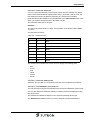
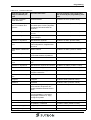
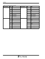
Version
1
2
Date
29.07.2005
30.11.2005
3
4
01.03.2006
01.02.2007
Modifications
First Edition
Validation changed, new script class and methods, new
system variables, IP settings, transparency buttons, new
options settings, data set names for recipes, project
names, new library functions, transfer of project files, USB
printer, chapter "Switching On" revised
Remedying of general faults, design changes
Working with scripts removed, modifications concerning
SP2 and SP3 added
This manual, including all illustrations contained herein, is copyright protected. Use of this manual by any third
party in departure from the copyright provision is forbidden. No part of this manual may be reproduced, translated or electronically or photographically archived or altered without the express written consent from Sütron
electronic GmbH. Violations shall be cause for damage liability.
Sütron electronic reserves the right to make any changes that contribute to technical improvement.
Overall Table of Contents
Overall Table of Contents
1
2
Important Notes ....................................................................................................... 1-1
1.1
Symbols .................................................................................................... 1-1
1.2
Safety Notes ............................................................................................. 1-1
1.3
Intended Use............................................................................................. 1-1
1.4
Target Group............................................................................................. 1-1
Programming ........................................................................................................... 2-1
2.1
Programming Interface ............................................................................. 2-1
2.2
File Menu .................................................................................................. 2-3
2.2.1
File Menu, Open a Project Folder ........................................................ 2-3
2.2.2
File Menu, New Project Folder ............................................................ 2-3
2.2.3
File Menu, Save Project Folder ........................................................... 2-5
2.2.4
File Menu, Close Project Folder .......................................................... 2-5
2.2.5
File Menu, Exit ..................................................................................... 2-5
2.3
View Menu ................................................................................................ 2-5
2.4
Tools Menu ............................................................................................... 2-6
2.4.1
Tools Menu, Options............................................................................ 2-6
2.4.2
Tools Menu, Defining the Interface .................................................... 2-12
2.4.3
Tools Menu, Application ID ................................................................ 2-12
2.4.4
Tools Menu, Firmware Update .......................................................... 2-13
2.4.5
Tools Menu, Transmit S3 File, Download .......................................... 2-14
2.4.6
Tools Menu, Transmit S3 File, Upload .............................................. 2-15
2.4.7
Tools Menu, Transmit Recipe Data Sets ........................................... 2-16
2.4.8
Tools Menu, TSDiag+ ........................................................................ 2-17
2.4.9
Tools Menu, Documentation .............................................................. 2-17
2.4.10
Tools Menu, Translation Support....................................................... 2-19
2.4.11
Tools Menu, Import ............................................................................ 2-21
2.4.12
Tools Menu, Export............................................................................ 2-25
2.4.13
Tools Menu, Optimizing a Database.................................................. 2-25
2.5
Help Menu............................................................................................... 2-26
2.5.1
Help Menu, Contents ......................................................................... 2-26
2.5.2
Help Menu, Index............................................................................... 2-26
2.5.3
Help Menu, Browse ........................................................................... 2-26
2.5.4
Help Menu, About .............................................................................. 2-26
2.5.5
Help Menu, Sütron Homepage .......................................................... 2-27
2.5.6
Help Menu, Netviewer ....................................................................... 2-27
2.5.7
Help Menu, Tip Of The Day ............................................................... 2-27
2.6
Terminal Type ......................................................................................... 2-28
2.6.1
Terminal Type, Change ..................................................................... 2-28
2.6.2
Terminal Type, Memory Size ............................................................. 2-28
i
Overall Table of Contents
2.6.3
Terminal Type, Touch Parameters .................................................... 2-29
2.6.4
Terminal Type, Color Palette ............................................................. 2-29
2.6.5
Terminal Type, Fonts ......................................................................... 2-29
2.6.6
Terminal Type, Terminal Orientation ................................................. 2-30
2.7
Comment................................................................................................. 2-30
2.8
Demomode.............................................................................................. 2-30
2.9
Communication ....................................................................................... 2-31
2.9.1
Protocol Selection .............................................................................. 2-31
2.9.2
PC >> Terminal .................................................................................. 2-31
2.9.3
Terminal >> Printer & Scanner .......................................................... 2-32
2.9.4
Protocol, Loop-through Operation...................................................... 2-34
2.9.5
Encoding of Alphanumerical Strings .................................................. 2-35
2.10
Languages .............................................................................................. 2-35
2.10.1
System Defaults ................................................................................. 2-35
2.10.2
Screens .............................................................................................. 2-37
2.10.3
Subscreens ........................................................................................ 2-41
2.10.4
Help Screens ..................................................................................... 2-41
2.10.5
Global Function Keys ......................................................................... 2-42
2.10.6
Message System ............................................................................... 2-43
2.10.7
Recipes .............................................................................................. 2-51
2.10.8
Print Logs ........................................................................................... 2-55
2.10.9
Subprint Logs ..................................................................................... 2-58
2.10.10
Language Resources ......................................................................... 2-58
2.11
2.11.1
User Management, Passwords .......................................................... 2-68
2.11.2
User Management, Parameters ......................................................... 2-69
2.12
Scripts ..................................................................................................... 2-69
2.12.1
Scripts, General ................................................................................. 2-69
2.12.2
Variable List ....................................................................................... 2-70
2.12.3
Planned Tasks ................................................................................... 2-70
2.13
Supplementary Functions ....................................................................... 2-71
2.13.1
Supplementary Functions, Polling Times........................................... 2-71
2.13.2
Supplementary Functions, Polling Area ............................................. 2-71
2.13.3
Supplementary Functions, Transfer Date & Time .............................. 2-72
2.13.4
Supplementary Functions, Receive Date & Time .............................. 2-72
2.13.5
Supplementary Functions, Reset Running Time Meters.................... 2-72
2.13.6
Supplementary Functions, Set Running Time Meters ....................... 2-73
2.13.7
Supplementary Functions, Unicode ................................................... 2-73
2.13.8
Supplementary Functions, Status Information ................................... 2-76
2.13.9
Supplementary Functions, Data Input................................................ 2-77
2.13.10
Supplementary Functions, Screensaver ............................................ 2-77
2.14
2.14.1
ii
User Management................................................................................... 2-68
Resources ............................................................................................... 2-78
Images and Symbols ......................................................................... 2-78
Overall Table of Contents
2.14.2
2.15
3
Image Lists ........................................................................................ 2-80
Project Management............................................................................... 2-81
2.15.1
Project Management, Activating a Project ......................................... 2-81
2.15.2
Project Management, Languages ...................................................... 2-81
2.15.3
Project Management, Communication............................................... 2-81
2.15.4
Project Management, Terminal File ................................................... 2-81
2.15.5
Terminal Ethernet Settings ................................................................ 2-84
Tutorial..................................................................................................................... 3-1
3.1
Working with Program Call Parameters.................................................... 3-1
3.2
Working with Screens ............................................................................... 3-3
3.2.1
Screen Structure .................................................................................. 3-3
3.2.2
System Screens................................................................................... 3-3
3.2.3
Input/Output Screen............................................................................. 3-4
3.3
Working with Screen Objects.................................................................... 3-5
3.3.1
Static Text ............................................................................................ 3-5
3.3.2
Text Field ............................................................................................. 3-5
3.3.3
Variables .............................................................................................. 3-6
3.3.4
Background Image............................................................................. 3-32
3.3.5
Buttons............................................................................................... 3-33
3.3.6
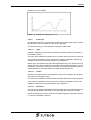
Set of Curves (Graph)........................................................................ 3-43
3.3.7
Recipe Field ....................................................................................... 3-47
3.3.8
Table Field ......................................................................................... 3-47
3.3.9
Message Field ................................................................................... 3-48
3.3.10
Creating System Icons / Button Display ............................................ 3-49
3.3.11
Creating Navigation Buttons .............................................................. 3-49
3.3.12
Output Variables ................................................................................ 3-49
3.3.13
Input Variables ................................................................................... 3-51
3.3.14
Dynamic and Static Attributes............................................................ 3-51
3.3.15
Aligning Selected Elements to the Grid ............................................. 3-54
3.3.16
Aligning Selected Elements ............................................................... 3-54
3.4
Working with System Variables .............................................................. 3-55
3.4.1
Basic Functions ................................................................................. 3-55
3.4.2
Communication SER1 ....................................................................... 3-60
3.4.3
Error Statistics SER1 ......................................................................... 3-64
3.4.4
Communication SER2 ....................................................................... 3-65
3.4.5
Real-Time Clock ................................................................................ 3-67
3.4.6
Serial Message System ..................................................................... 3-70
3.4.7
Parallel Message System .................................................................. 3-76
3.4.8
Printer Control.................................................................................... 3-79
3.4.9
Menu Control / Keys .......................................................................... 3-80
3.4.10
Password ........................................................................................... 3-88
3.4.11
Recipes .............................................................................................. 3-90
3.4.12
Running Time Meters ........................................................................ 3-97
iii
Overall Table of Contents
3.4.13
Loop-through Operation ..................................................................... 3-97
3.4.14
Loadable Character Set ..................................................................... 3-98
3.4.15
Maintenance (Service) ....................................................................... 3-98
3.4.16
Editors .............................................................................................. 3-101
3.4.17
Help.................................................................................................. 3-103
3.4.18
Print Logs ......................................................................................... 3-105
3.4.19
Compact Flash Card ........................................................................ 3-106
3.4.20
Set of Curves (Graphs) .................................................................... 3-108
3.4.21
Image Parameters ........................................................................... 3-109
3.4.22
Script Processing ............................................................................. 3-109
3.5
Working with Libraries........................................................................... 3-110
3.6
Working with Edit Screens .................................................................... 3-111
3.7
Working with Recipes............................................................................ 3-113
3.7.1
Structure of a Recipe ....................................................................... 3-115
3.7.2
Working with Recipes and Data Sets............................................... 3-115
3.7.3
Data Set Transfer to/from Controller ................................................ 3-117
3.8
3.8.1
Internal Messages............................................................................ 3-124
3.8.2
System Icon ..................................................................................... 3-124
3.8.3
Suppressing the Display of Terminal Messages .............................. 3-127
3.8.4
Error Messages................................................................................ 3-127
3.8.5
External Messages .......................................................................... 3-136
3.8.6
Serial Message System ................................................................... 3-141
3.8.7
Parallel Message System (Status Messages) ................................. 3-142
3.8.8
Settings for Status Messages .......................................................... 3-142
3.8.9
Memory Requirement for Messages and Data Sets ........................ 3-144
3.9
iv
Working with Messages ........................................................................ 3-123
Working with Password Protection........................................................ 3-145
3.9.1
Reactivate Password Protection ...................................................... 3-147
3.9.2
Password Screen and Password Functions .................................... 3-147
3.10
Working with Running Time Meters ...................................................... 3-147
3.11
Working with Control Codes.................................................................. 3-149
3.11.1
Delete Data Logger .......................................................................... 3-150
3.11.2
Trigger Data Logger ......................................................................... 3-150
3.11.3
Write Values of Running Time Meters to Controller......................... 3-150
3.11.4
Switch to Another Language ............................................................ 3-151
3.11.5
Activating Recipe and Data Sets from the Controller....................... 3-151
3.11.6
Automatic Data Release for Scanner Module .................................. 3-151
3.11.7
Reload Event-Controlled Variable Values........................................ 3-151
3.11.8
Transfer Single Data Set from Operating Device to Controller ........ 3-151
3.11.9
Delete Acknowledged Messages from Serial Message Memory ..... 3-152
3.11.10
Cancel Printing the Print Log ........................................................... 3-152
3.11.11
Printing a Print Log .......................................................................... 3-152
3.11.12
Printing a Data Set ........................................................................... 3-153
Overall Table of Contents
3.11.13
Set Clock in Operating Device ......................................................... 3-153
3.11.14
Data Set Transfer from Controller to Operating Device
(Block Mode).................................................................................... 3-153
3.11.15
Data Set Transfer from Operating Device to Controller ................... 3-153
3.11.16
Send Keyboard Image to Controller ................................................ 3-154
3.11.17
Data Set Transfer from Controller to Operating Device
(Single Mode) .................................................................................. 3-154
3.11.18
Erase Serial Message Memory........................................................ 3-154
3.11.19
Refresh Message System................................................................ 3-154
3.12
Working with a Real-Time Clock in the Operating Device .................... 3-155
3.12.1
Date and Time Image ...................................................................... 3-155
3.12.2
Setting the Real Time Clock from the Controller ............................. 3-156
3.12.3
Transferring the Real-Time to the Controller ................................... 3-156
3.13
Working with the Help Function ............................................................ 3-156
3.13.1
Help Screen for Screens.................................................................. 3-157
3.13.2
Help Screen for Input Variable......................................................... 3-157
3.13.3
Help Screen for Message Screens .................................................. 3-157
3.14
Working with Function Keys / Softkey Functions .................................. 3-158
3.14.1
Direct Selector Keys ........................................................................ 3-158
3.14.2
Function Keys in the Controller........................................................ 3-158
3.14.3
Softkeys ........................................................................................... 3-159
3.14.4
Reaction Time of Function and Soft Keys ....................................... 3-160
3.14.5
Using Control Keys as Function Keys ............................................. 3-160
3.14.6
Status LEDs of Function Keys ......................................................... 3-160
3.15
Working with the Cyclic Polling Area .................................................... 3-161
3.15.1
Byte-Oriented Polling Area .............................................................. 3-162
3.15.2
Word-Oriented Polling Area ............................................................. 3-163
3.15.3
Serial Message Channel.................................................................. 3-164
3.15.4
Image of Status LEDs ...................................................................... 3-164
3.15.5
Polling Time ..................................................................................... 3-164
3.15.6
Size of the Polling Area ................................................................... 3-165
3.15.7
Read Coordination Byte................................................................... 3-165
3.15.8
Write Coordination Byte ................................................................... 3-168
3.16
Working with Scanners ......................................................................... 3-170
3.16.1
Parameters for Scanner CLV410 from Sick..................................... 3-170
3.16.2
Parameters for Scanner DL 80-11 from Data Logic ........................ 3-171
3.16.3
Parameters for Scanner DL910 from Data Logic............................. 3-172
3.16.4
Parameters for Scanner DLL 5012-M1 from Data Logic ................. 3-174
3.16.5
Parameters for Scanner DLL 6010-M1 from Data Logic ................. 3-175
3.16.6
Parameters for Scanner BB Snapshot ST from Percon .................. 3-176
3.17
How do I Configure the Contrast/Brightness Setting for the Operating
Device? ................................................................................................. 3-177
3.18
Renaming Objects ................................................................................ 3-178
3.19
Image of the User-Mode Switch............................................................ 3-178
v
Overall Table of Contents
3.20
Image of the Screen Number ................................................................ 3-178
3.21
Image of the Keyboard.......................................................................... 3-178
3.21.1
Keyboard Image for the BT03AM .................................................... 3-179
3.21.2
Keyboard Image for the BT05AM .................................................... 3-181
3.21.3
Keyboard Image for the BT07AM .................................................... 3-183
3.21.4
Keyboard Image for the BT21AM .................................................... 3-185
3.22
3.22.1
Boot Process.................................................................................... 3-187
3.22.2
Loading Procedure on Windows CE Operating Procedure.............. 3-188
3.22.3
Function of the AppStarter.exe Program ......................................... 3-196
3.22.4
Function of the TSvisLD.exe Program ............................................. 3-196
3.22.5
Memory Media Used ........................................................................ 3-196
3.22.6
Important Files and Directories ........................................................ 3-197
3.23
Communication With a Controller ......................................................... 3-197
3.24
Working on Older Projects With TSwin .net 4.xx .................................. 3-197
3.24.1
A
vi
Starting the Operating Devices ............................................................. 3-187
Download of Old Projects (S3 Files) ................................................ 3-198
Index ....................................................................................................................... A-1
Important Notes
1
Important Notes
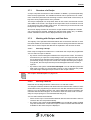
1.1
Symbols
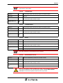
The symbols in this manual are used to draw your attention on notes and dangers.
Danger
This symbol is used to refer to instructions which, if ignored or not carefully followed
could result in personal injury.
Note
This symbol indicates application tips or supplementary notes.
Reference to source of information
This symbol refers to detailed sources of information on the current topic.
1.2
Safety Notes
–
Read this manual carefully before using the software. Keep this manual in a
place where it is always accessible to all users.
–
The user manual, in particular the safety notes, must be observed by all personnel working with the software and the programmed device.
–
Observe the accident prevention rules and regulations that apply to the operating
site.
–
Installation and operation must only be carried out by qualified and trained personnel.
1.3
–
Intended Use
The software has to be used for programming operating devices exclusively. Every other use is not permitted.
1.4
Target Group
All configuration and programming work in connection with the automation system
must be performed by trained personnel only (e.g. qualified electricians, electrical engineers).
The configuration and programming personnel must be familiar with the safety concepts of automation technology.
1-1
Important Notes
1-2
Programming
2
Programming
2.1
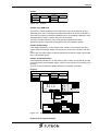
Programming Interface
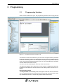
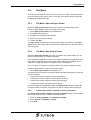
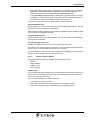
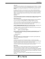
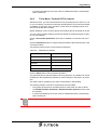
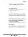
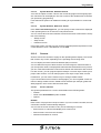
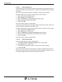
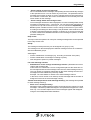
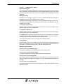
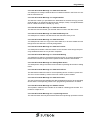
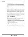
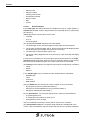
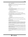
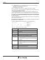
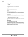
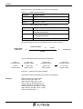
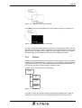
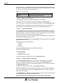
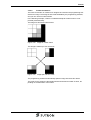
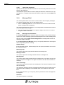
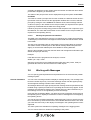
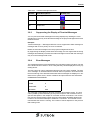
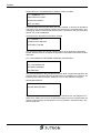
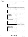
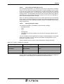
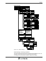
When all of the windows are open, the programming interface looks roughly like this:
Figure 2-1
Complete overview of TSwin .net
The interface consists of windows that you can dock at a required location (dockable
windows) or position anywhere you like (floating windows). The remaining free space
is used as the working area. In this working area, the programming software displays
screen, list, recipe and graphic editors that you can use to edit objects (for example,
a screen editor for the main screen).
The menu bar and toolbar appear at the top of the main window.
The status bar appears at the bottom of the main window. It displays the particular
properties of the elements currently selected in an editor (position and size, for example).
Project Folder window
The Project folder window displays the entire project in the form of a tree structure.
You can expand any branches within the tree structure that are marked with a plus
sign. Additional branches or objects may appear below the branches.
2-1
Programming
Within the project folder, you can move or copy objects using the drag & drop function
(for example, to add a language and a controller to a project).
Properties window:
The Properties window always displays the properties of the particular branch or object that is currently selected in the project folder. Any changed properties are transferred directly by the programming software.
Output window:
The Output window shows all messages that may be generated during compilation
of the terminal file. You may print out the window content by clicking the printer symbol.
Tools window:
You can choose screen objects or library in the tools window.
Screen objects:
To create screen objects, first select a tool from the Tools window. The object icon
is then displayed on the mouse pointer while you work with a tool.
Library:
You put screen objects into the library to use them again in other projects. To call a
library function perform a right-click on the title bar of the library window.
See chapter “Working with Screen Objects“ on page 3-5.
See chapter “Working with Libraries“ on page 3-110.
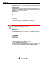
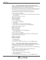
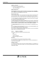
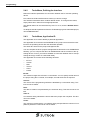
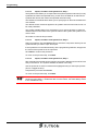
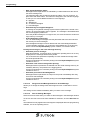
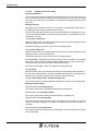
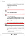
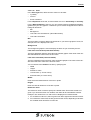
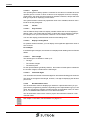
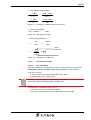
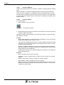
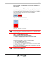
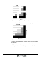
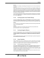
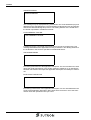
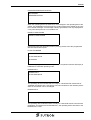
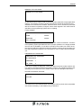
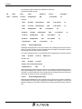
Hiding windows:
Using the Autohide attribute from the context menu, you automatically minimize a
window to the size of an icon when it is not in use. This icon is then displayed at the
very bottom of the main window. If you move the mouse pointer over the icon, the
window reopens in its original location.
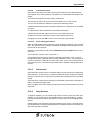
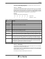
Figure 2-2
Window displayed as icon
To dock a window, follow these steps:
1. Using the mouse, right-click the title bar of the window.
2. Select Dockable from the context menu.
Keeping the left-hand mouse button depressed, drag the window to the edge of the
main window until the window dimensions match the size of the main window.
Release the mouse button.
To undo the dock operation, select Floating from the context menu.
2-2
Programming
2.2
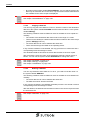
File Menu
The File menu contains all of the functions you require to create a new project folder,
open an existing project folder, save or close the active project folder and quit the
programming software package.
2.2.1
File Menu, Open a Project Folder
Select the Open project folder menu item to open an existing project folder.
Follow the steps below to open an existing project folder:
1. Select Open project folder from the File menu.
2. The Open dialog appears.
3. Navigate to the project folder required.
4. Select the project folder required.
5. Confirm with OK.
The Open dialog closes and the selected project folder is opened. In the Project
folder window, the project folder is entered as a single folder icon with the name of
the terminal type.
2.2.2
File Menu, New Project Folder
Select the New project folder menu item to create a new project folder. You can
start by using an empty or predefined template.
Use predefined templates if you want to save time, especially for programming operating devices equipped with touch screens. When using these templates, all you
need to do is adapt the design and implement your own additions.
You can choose to create the new project folder as a project, template or library.
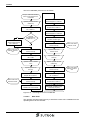
Follow the steps below to create a new project folder:
1. Select New project folder from the File menu.
The wizard used for creating a new project folder now opens and guides you through
a series of dialogs:
–
Create project folder, template or library (templates)
–
Create project folder, template or library (place to store)
–
Create project folder, template or library (terminal type)
–
Create project folder or template (protocol type)
Once the wizard has completed all steps, the Project folder window contains the
new project folder as at least one project icon with the name of the terminal type.
2.2.2.1
Create Project Folder, Template or Library (Templates)
The Create project folder, template or library (templates) dialog is the first dialog
that the wizard shows you to create a new project folder.
1. Select an empty template or a predefined template.
2. Select Project or Template or Library.
3. Click Next.
2-3
Programming
2.2.2.2
Create Project Folder, Template or Library (Place to Store)
The Create project folder, template or library (place to store) dialog is the second
dialog that the wizard shows you to create a new project folder.
Select the directory where you want to save the new project folder. If you do not select a directory, the programming software’s root directory is automatically used.
The storage location last entered is automatically offered again.
A list with the last 8 project folders is shown beneath the input field.
Follow the steps below (variant 1):
1. Enter a name for the new project folder into the input field (overwrite existing entry, if necessary).
Make sure the file extension is correct:
Template = File name.tst
Project = File name.tsw
Library = File name.tsb
2.
Click the Next >button.
Follow the steps below (variant 2):
1. Click Select.
2. Select a directory in the dialog window that appears.
3. Enter a name for the new project folder in the File name field.
Make sure the file extension is correct:
Template = File name.tst
Project = File name.tsw
Library = File name.tsb
4. Confirm your actions by clicking the Save button.
5. Click the Next >button.
Follow the steps below (variant 3):
1. Select the name of an existing project folder from the bottom display field.
Make sure the file extension is correct:
Template = File name.tst
Project = File name.tsw
Library = File name.tsb
2. Change the name.
3. Click the Next > button.
You can also return to the previous page. To do so, click the Back < button.
2.2.2.3
Create Project Folder, Template or Library (Terminal Type)
The Create project folder, template or library (terminal type) dialog is the third
dialog that the wizard shows you to create a new project folder.
If you have already created a project folder, the last selection is automatically highlighted.
The icons illustrate the graphical capabilities of the individual devices.
Follow the steps below to specify the terminal type:
1. Select a terminal type from the list.
2. Select the memory size of your device (if possible).
3. Click the Next >button.
You can also return to the previous page. To do so, click the Back < button.
2-4
Programming
2.2.2.4
Create Project Folder or Template (Protocol Type)
The Create project folder or template (templates) dialog is the fourth and final dialog that the wizard shows you to create a new project folder.
If you have already created a project folder, the last selection is automatically highlighted.
The icons indicate whether this is a field bus connection or a point-to-point connection.
Follow the steps below to specify the protocol type:
1. Select a protocol type from the list.
2. Click the Finish button.
You can also return to the previous page. To do so, click the Back < button.
2.2.3
File Menu, Save Project Folder
Select the Save project folder menu item to save the current project folder. This action overwrites the existing file rather than creating a new one.
2.2.4
File Menu, Close Project Folder
Use Close project folder from the menu to complete processing of the current
project folder.
If you have made additional changes to the project folder since the last time you
saved, the system asks you whether you want to save the project folder before closing.
2.2.5
File Menu, Exit
To quit the programming software, use the Exit menu item.
If a project folder is still open, this is closed first. If you have made changes to the
current project folder before closing, the system asks you whether you want to save
the project folder.
2.3
View Menu
The view menu offers the following menu items:
–
Zoom out
–
Zoom in
–
Restore workspace
–
Close all windows
–
Project folder
–
Properties
–
Tools
–
Output
Zoom in:
If an editor is open (i.e. screen editor) the view on the screen is zoomed out by one
step each per click on the menu item.
2-5
Programming
Zoom out:
If an editor is open (i.e. screen editor) the view on the screen is zoomed in by one
step each per click on the menu item.
Restore workspace:
Select the menu item Restore workspace to get back the previous arrangement,
size and number of opened windows.
Close all windows:
Select the menu item Close all windows to watch the work space without any other
windows.
Project folder:
Opens and closes the Project folder window. The check beside the menu item indicates that the window is open.
Properties:
Opens and closes the Properties window. The check beside the menu item indicates that the window is open.
Tools:
Opens and closes the Tools window. The check beside the menu item indicates that
the window is open.
Output:
Opens and closes the Output window. The check beside the menu item indicates
that the window is open.
2.4
Tools Menu
The Tools menu offers you a number of different functions, depending on the particular element within the project tree that is currently selected.
2.4.1
Tools Menu, Options
These are the options you use to define the default settings for the programming software.
You can change these settings at any time. These options are saved together with
the project.
2.4.1.1
Options, Project Management
The project management options are divided into the following areas.
–
Backup databases
–
Current database
–
Template directory
–
Undo (single-step undo).
Backup Databases area:
Select one of three possible backup variants.
–
2-6
If you select None, no backup is generated when you reopen a database.
Programming
–
If you select One (single backup), a backup file is generated when you reopen a
database. The backup file is then overwritten every time this database is reopened. This backup file is always called DATABASENAME.000.
–
If you select Many (multiple backup), a backup file is generated when you reopen
a database. Another backup file is created every time this database is opened.
These files are assigned ascending numbered file extensions.
If you wish, you can also store the backup files in compressed form.
Current Database area:
Decide whether you want to compress the current database after exiting it. This will
reduce the memory requirement considerably.
Always make sure that you have enough memory available on your hard disk to allow
you to unpack a compressed file again.
Template Directory area:
Select the path to be used for the templates. You can then create a new database
on the basis of a template.
Undo (single-step undo) area:
Activate the Single-Step Undo check box to cancel the last action.
The undo function does not apply to all actions. To check whether a particular action
can be undone, view the status of the button in the tool bar.
You must enable the undo function before opening or creating a file. The undo function can not be reversed while you are programming.
2.4.1.2
Options, Graphic Editors
The graphic editor functions are divided into the following areas.
–
Capture
–
Representation
–
Capture / Grid
–
Status display.
Capture area:
You can define separate settings for the horizontal and vertical capture function. Elements that are not aligned by means of a grid can be positioned more easily in a
screen using the capture function.
You can choose between the following options:
–
Deactivate the capture function
–
Adopt the standard font (norm font) values for the capture function
–
Apply the numerical values to the horizontal and vertical direction.
2-7
Programming
Capture / Grid area:
In this area you can specify whether
–
You want to display a grid in screens,
–
The color of the grid.
Status Display area:
Decide whether you want to display the position of the mouse cursor using Pixel
units or Grid units in the status bar. The Grid unit corresponds to the area taken up
by one character of the standard font (norm font).
Representation area:
You can assign separate colors to the input and output variables to differentiate between them more clearly. A colored frame is then displayed around the variable.
This area also lets you choose the zoom factor to be used when displaying a screen.
To display Background images with a frame in screens (so they are more apparent), select the corresponding check box.
The Brief info about screen element variable check box activates a small window
with a brief explanation for the element in the screen selected by the mouse. If the
element is linked to a controller variable, the full controller address is displayed. If the
element is linked to a system variable, the name of the variable is displayed.
To display subscreens that are linked, you must select the corresponding check
box.
With the Display referenced image list check box, you can decide whether to display the default image in selection image variables.
By activating the Fit working area to editor size check box, you can ensure that the
graphic editor is maximized in the window.
2.4.1.3
Options, List Editors
The list editor options are divided into the following areas.
–
Font
–
Variable list
–
Text and image list
–
Default text length for text lists
Font area:
This area displays the font used in the list editors by default.
To change a font, click Select. Any existing entries in a list are automatically converted to the selected font.
Variable List area:
To activate an automatic syntax check for the address definition in a variable list, select the appropriate check box in this area. The check is performed after a line of the
variable list is exited.
2-8
Programming
Text and Image List area:
When the Display values hexadecimally check box is selected, you can also display and enter the values in text and image lists in hexadecimal format. Always precede the hexadecimal value with the letter H.
Default Text Length for Text Lists area:
This area allows you to determine whether the length of texts entered in text lists is
to be unlimited or limited. If you do not want texts to exceed a specific length, enter
a maximum length in the Single character field.
2.4.1.4
Options, Global Settings
The global settings options are divided into the following areas.
–
Representation,
–
Options for S3 file generation,
–
While starting,
–
Open editors,
–
When inserting from a library.
Representation area:
To display flashing elements in a screen in the strike through format, select the Display Attribute Flashing check box.
Options for S3 File Generation area:
You only need this entry field if a project cannot be compiled without errors and you
call on help from our hotline. In this case you will get option codes with whose help
you will find out further information about the compilation error.
While starting area:
Check the checkbox if the previous opened file should be loaded automatically.
Display only existing project files within the project files list by checking the corresponding check box.
Open editors area:
Since now you had to open an editor by a double-click onto the item of the project
folder. Now you only need to perform a single click as default. To open the editors
with an double-click again, uncheck the checkbox with single click.
When Inserting from a Library area:
Determine the steps the programming software should take if there is already an element with a particular name in the project and you want to add an element with the
same name from a library.
Choose one of the options below:
1. The element from the library is assigned a different name when it is added to the
project.
2. The element from the library is not added.
3. A prompt is displayed. This must be confirmed before you can add the element.
Regarding 1: The date and time are appended to the name of the element being
added. This clearly differentiates the element from the existing element.
2-9
Programming
2.4.1.5
Options, Message Editor
Using the message editor options, you can make basic settings for the editor that you
use to create messages. The message editor options are divided into the following
areas.
–
Grid
–
Status display
–
Representation
–
Message number
Grid area:
You can display a grid for character boundaries as an input help. Select the Display
check box to activate this function. You can also select a Color for the grid.
Status Display area:
The status bar at the bottom of the screen in the message editor shows the current
cursor position, displayed in either Dots (pixel) or Grid units.
Representation area:
With the Output variables field, you can select the Color of output variables in the
message editor from a list provided. This makes it easier for you to identify the output
variable within a message text.
With the Zoom field, select the default zoom factor to be used for displaying a message in the message editor.
You can also choose to display a brief description of the variables (name and address) while the mouse cursor is pointed at the variables area.
In addition, you can display the width of the terminal display using markers in the
message editor.
Message Number area:
The area displays the default font to be used to display the message numbers. To
change the default font, use the mouse to click the Select font button.
To have messages automatically numbered in sequence when created, activate the
Automatic message number(ing) check box.
When the Display values hexadecimally check box is selected, you can also enter
and display the message numbers in hexadecimal format. Always precede the hexadecimal value with the letter H (example: H001A).
2.4.1.6
Options, Print Log Editors
The print log editor options provide a number of settings that you can use to define
the appearance of the print log in the editor.
You can define settings in the following areas:
2-10
–
Font
–
Grid
–
Representation.
Programming
Font area:
This area shows the default font used to edit the print logs in the editor. To change
the default font, use the mouse to click the Select font button. You can only select
fonts that are non-proportional (OEM fonts). The size of the characters is also restricted.
By setting up the printer to use the same font, you create a WYSIWYG display.
Provided that your print logs do not contain characters that are reserved in the ASCII
table for control characters, you can authorize conversion to ASCII for translation
support. If you are using these reserved characters, this information would be lost
during conversion.
Grid area:
You can display a grid for character boundaries as an input help. Select the Display
check box to activate this function. You can also select a Color for the grid.
Representation area:
You can use different colors to differentiate between elements in the print log that
have been assigned the Non-printable and Output variables properties.
Select a zoom factor to increase the screen segment in the print log editor.
You can also choose to display a brief description of the variables (name and address) while the mouse cursor is pointed at the variables area.
Select the Display subprint log check box if you want to be able to distinguish subprint log elements from elements belonging to the main print log.
To adjust the display of the print log editor when opened to the size of the working
field, select the corresponding check box.
2.4.1.7
Options, Translation Support
For the translation support function, you can decide in general whether or not to use
an extended functionality. The following areas are provided for these options.
–
While Exporting and
–
While Importing
Export area:
With While Exporting, you can define whether to use pixels or grids (characters)
when specifying the position of an element.
Sorting area:
Possible sorting options are Horizontally-Vertically or Vertically-Horizontally.
Horizontally-Vertically means you want to sort text items using the horizontal position
as the main criterion and the vertical position as the sub-criterion.
Vertically-Horizontally means you want to sort text items using the vertical position
as the main criterion and the horizontal position as the sub-criterion.
Import area:
Specify whether you want the programming software to notify you if the position of a
translated element has changed in relation to the original element position.
You can also determine whether you want a warning to be displayed if the translated
text is longer than the original text. If this is the case, you can double-click the corresponding message to open the text editor (screen editor, message editor, text list editor) and reposition or check the text.
However, any changes to position or text length made here will not be reflected in the
export file.
2-11
Programming
2.4.2
Tools Menu, Defining the Interface
Define the interface parameters for connection between the PC and the operating
device.
First, select the COM interface whose values you wish to change.
The Interface Parameters area contains default values. To change those values,
simply select other values from the appropriate lists.
The default values can be restored at any time. To do so, click the Default values
button.
To adopt the interface parameters from the S3 file belonging to the translated project,
click the S3 file button.
2.4.3
Tools Menu, Application ID
The application ID is used to identify a particular application.
The application ID is stored in the S3/SB/CB file of a project and is therefore transferred to the operating device after the download operation.
The same ID is stored in the project management file.
You can compare the ID of a project management file and the ID of an S3/SB/CB file.
Similarly, you can compare the IDs of an S3/SB/CB file and the contents of the operating device. For this, you need to establish a connection between the PC and operating device (by means of a download cable).
The application ID consists of the following elements:
–
ID Text
–
Version
–
Date
–
Time of
–
Count
–
Postfix
ID text:
The maximum length of the ID text is 13 characters. You can specify the file name of
the project using the 8.3 format, for example, and edit the ID text as required.
Version:
The version of the programming software is identified by a 5-character string. This
text can not be edited.
Date:
The date of creation is represented by a 6-character string. This text can not be edited.
Time of:
A 6-character string indicates the time at which the project was compiled. This text
can not be edited.
Count:
The counter is represented by a 4-character string and specifies the number of compilations performed. This text can not be edited.
2-12
Programming
Postfix:
The Postfix is a random number consisting of 2 characters. This number can not be
edited.
Use the Refresh button to update the entries in all fields.
The File name area allows you to select an S3/SB/CB file created using the programming software and output its application ID.
To do this, select the file and then click the Refresh button in the S3/CB file area.
In the Operating device area, you can read the application ID from the connected
operating device. You can either define the interface parameters for the connection
separately or use the parameters from the selected S3/SB/CB file. To define the interface parameters, click the Parameters button.
2.4.4
Tools Menu, Firmware Update
You can easily replace the firmware for the operating devices by using the option that
allows you to load the firmware together with the programming software on the operating device. If the firmware is no longer up-to-date it is possible to easily exchange
it with a newer version. This applies only to terminals containing the firmware in
FLASH memory. This relies to all operating devices with 386EX processor and all operating devices with 25 pin universal interface.
If the firmware is loadable you can read the firmware version while initialization of the
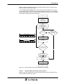
terminal takes place.
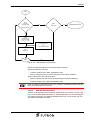
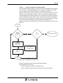
Firmware download process:
1.
Select the directory and the file name for the S3 file of the firmware.
2.
Select the terminal.
3.
Select the firmware version.
4.
Create the firmware file (S3 file).
5.
Download the firmware to the device
Enter a target directory and a file name for the firmware file. Alternatively, select an
existing directory and file.
Select the check box to start a download immediately after the firmware file has been
created.
Then click Next > to continue.
2.4.4.1
Firmware Update, Terminal Type
Select a terminal type from the left list box.
If the device can be equipped with memories of different sizes, select the appropriate
memory size value from the right list box.
Then click Next > to continue. Alternatively, click < Back to return to the previous
window.
2.4.4.2
Firmware Update, Version
Select a firmware version.
Note that the listed firmware versions only apply to the previously selected device.
Then click Next > to continue. Alternatively, click < Back to return to the previous
window.
2-13
Programming
2.4.4.3
Firmware Update, Generate
The last window of this wizard illustrates the progress of the file creation process.
Once the firmware file has been created successfully, you can either
–
Immediately load the file into the device (download cable required) or
–
Load the file into the device at a later stage.
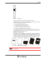
Follow the steps below to load the file into the operating device immediately:
1. Connect the device with the PC using the download cable.
2. Set the user mode switch of the operating device to Delete Application Memory.
3. Connect the device with the supply voltage.
4. Once the message Flash is Erased (or a similar message) is displayed, reset the
user mode switch to the normal position (leave operating device switched on).
5. When the device displays DOWNLOAD 1, click the Download button.
The download is complete when the device reboots.
2.4.5
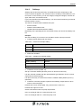
Tools Menu, Transmit S3 File, Download
You can load an S3 file (compiled project) into an operating device with serial interface individually. To do so, you directly connect the PC with the operating device using a download cable or a modem. In this case, the operating device must also be
connected with a modem.
Enter the S3 file in the File area.
In the Download Type area, choose between the following:
–
Default, if you want to download directly from a PC to the operating device (baud
rates automatically adjusted).
–
Modem (fixed parameters), if you are using modems for the connection (fixed
baud rate setting).
–
Adjustable parameters (configurable parameters) if you want to work with special
interface settings.
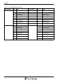
To change the parameters for the serial interface, click the Parameters button.
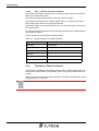
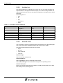
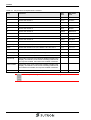
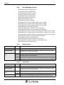
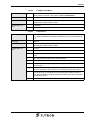
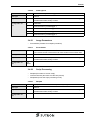
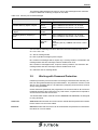
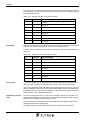
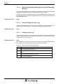
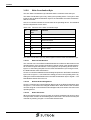
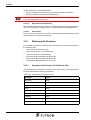
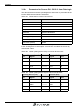
The parameters for the modem are assigned fixed values:
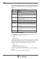
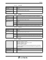
Table 2-1
Parameters for Modem
Parameter
Value
Baud rate
19200 Baud
Parity
Odd
Data bits
7
Stop bits
1
Handshake
Software handshake
In the Interface area, select the COM interface that you want to use to connect the
operating device.
To check and, if necessary, edit the application ID settings, click the App-ID button.
The following modem connection requirements must be fulfilled:
2-14
–
The system parameters for the SER2 interface must match the above values.
–
The Enable automatic download or Enable automatic upload check box must
be activated.
Programming
–
A modem (transparent) connection must be established before a download/upload is carried out.
2.4.6
Tools Menu, Transmit S3 File, Upload
With this function, you can load the S3 file from an operating device to the PC. To do
so, you can directly connect the PC with the operating device using a download cable
or establish a connection using a modem. In this case, the operating device must
also be connected with a modem.
Before uploading, enter a name for the S3 file so that the file can be stored on the PC.
You can use the interface settings stored in the S3 file for the S3 file transfer or specify your own settings.
Click the Use modem parameters check box to establish a connection with a modem.
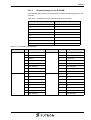
Click the Parameters button to configure the parameters of the serial interface or the
connected modem.
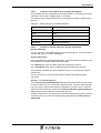
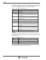
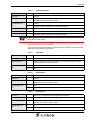
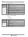
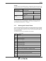
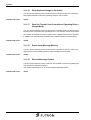
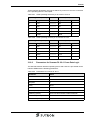
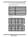
The following values must be set as modem parameters:
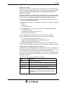
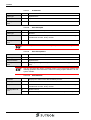
Table 2-2
Parameters for Modem
Parameter
Value
Baud rate
19200 Baud
Parity
Odd
Data bits
7
Stop bits
1
Handshake
Software handshake
Click the Start button to start the upload operation.
The upload function is primarily used for archiving purposes. The S3 files can not be
reloaded into the programming software (to make changes to the project, for example).
The cable used for uploading is the same as that used for downloading.
The following modem connection requirements must be fulfilled:
–
The system parameters for the SER2 interface must match the above values.
–
The Enable automatic download or Enable automatic upload check box must
be activated.
–
A modem (transparent) connection must be established before a download/upload is carried out.
See chapter “Download of Old Projects (S3 Files)“ on page 3-198.
2-15
Programming
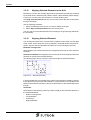
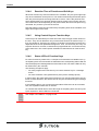
2.4.7
Tools Menu, Transmit Recipe Data Sets
The data set transfer tool (DSTT) is a tool for exchanging recipe data sets.
It uses two tree views to represent the structure of the recipes and data sets.
The structure of the data sets in a file or on an operating device is displayed on the
left side. The right side shows the structure of the data sets in a file.
You can exchange the data sets between the files and the operating device.
Highlighted data sets can be copied or deleted. You can change the write-over identifier of data sets in files.
To copy data sets, use the >> and << copy buttons.
The following menu items are available in a popup menu or via the keyboard:
–
Refresh structure
–
Copy
–
Paste
–
Delete
–
Select All
–
Overwriteable (Make over-writable)
–
Non-overwriteable (Make not overwriteable)
Note:
Data in a recipe data set can only be edited using the programming software.
You can use a popup menu to delete the messages in the status window of the data
set transfer tool.
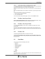
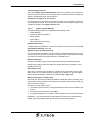
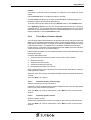
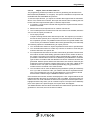
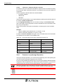
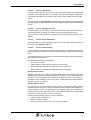
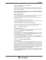
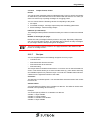
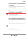
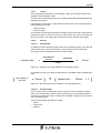
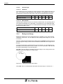
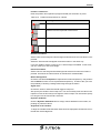
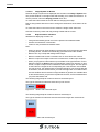
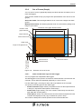
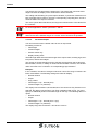
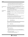
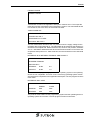
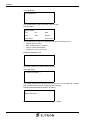
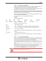
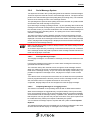
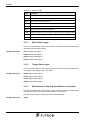
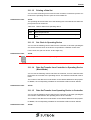
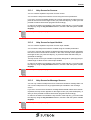
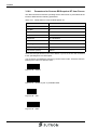
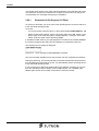
The parameters for the serial interface of the PC are displayed to the bottom left of
the dialog.
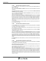
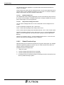
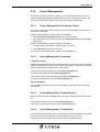
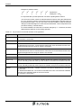
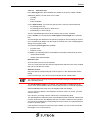
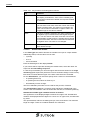
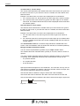
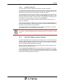
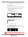
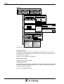
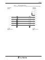
Figure 2-3
Interface parameters for data set transfer tool
These parameters are used to transfer a data set both to and from the operating device.
Meaning of the parameters:
2-16
–
COM 2 = Number of the serial interface
–
19200 Baud = Baud rate of transmission
–
7 = Number of data bits
–
1 = Number of stop bits
–
Odd = Not even parity
Programming
2.4.8
Tools Menu, TSDiag+
With TSDiag+ you get access to any operating device with Windows CE operating
system that is available within the connected ethernet.
With TSDiag+ you have the possibility of looking at the content of the display of the
operating device and interacting with the control unit so as if you would operate it directly.
In addition, you can transfer files to the operating device such as updated project
data or software updates.
See User Manual TSDiag+.
2.4.9
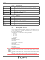
Tools Menu, Documentation
You can document the content of a project in an RTF file. To determine the scope of
documentation, select the required project elements arranged in a tree structure.
You can further adjust the documentation layout by selecting and deselecting different documentation parameters.
The following options are available:
–
Checking/unchecking a documentation element
–
Starting documentation for the selected element
–
Document from selected element downward
2.4.9.1
Documentation Parameters, Global Settings
In the Screen reference lists area, choose between two options: either display the
screen reference lists in the documentation with their name only or specify the current screen for a variable value.
If the screen reference list is specified by name only, the documentation includes a
reference to the list. The contents of the list are not output.
You can also specify the current screen to be switched to if a variable assumes the
value that you enter in the field next to the appropriate radio button.
2.4.9.2
Documentation Parameters, Projects
If you activate the Document general project information check box, the documentation support function takes account of all entries provided under general
project information.
2-17
Programming
2.4.9.3
Documentation Parameters, Screens
In the Variables area, choose whether you want to specify the variable positions in
pixels or grid units.
Select the Include numbers in graphic check box to have the variables of a screen
numbered.
The variable description function of a screen is only activated if the With variable description check box is activated.
Select the Empty documentation value for variables check box if you want only to
display a frame for the variable.
Select the Include text list strings in variable description check box in the Text
list area if you want to list the text strings of text lists linked to selection text variables.
For the text strings to be listed, the value entered in the Max. number of text list
strings field must be greater than the actual number of text list strings. This option
allows you to selectively document the text lists that have a limited number of text
string entries.
In the Function keys area, decide whether you want to document the functions of
function keys of a screen.
2.4.9.4
Documentation Parameters, Recipes
In the Variables area, choose whether you want to specify the position of variables
in recipes in pixels (dots) or grid units.
The variables in a recipe are displayed in a numerical sequence when you activate
the corresponding check box.
The description of the variables in a recipe only appears when you select the With
variable description check box.
Select the Include text list strings in variable description check box in the Text
list area if you want to list the text strings of text lists linked to selection text variables.
For the text strings to be listed, the value entered in the Max. number of text list
strings field must be greater than the actual number of text list strings. This option
allows you to selectively document text lists that have a limited number of text string
entries.
In the Data sets area, define whether you want to document the data set values for
the recipe.
2.4.9.5
Documentation Parameters, Help Screens
In the Variables area, choose whether you want to specify the position of variables
in help screens in pixels (dots) or grid units.
The variables in a help screen are displayed in a numerical sequence when you activate the corresponding check box.
The description of the variables in a help screen only appears when you select the
With variable description check box.
Select the Include text list strings in variable description check box in the Text
list area if you want to list the text strings of text lists linked to selection text variables.
For the text strings to be listed, the value entered in the Max. number of text list
strings field must be greater than the actual number of text list strings. You can thus
selectively document all text lists in a help screen that contain fewer than a particular
number of entries.
2-18
Programming
2.4.9.6
Documentation Parameters, Terminal Messages
In the Variables area, you can choose to specify the position of variables in system
messages using either pixel (dots) or grid units.
The variables in a system message are displayed in a numerical sequence when you
activate the corresponding check box.
The description of the variables in a system message only appears when you select
the With variable description check box.
Select the Include text list strings in variable description check box in the Text
list area if you want to list the text strings of text lists linked to selection text variables.
For the text strings to be listed, the value entered in the Max. number of text list
strings field must be greater than the actual number of text list strings. You can thus
selectively document all text lists in a system message that contain fewer than a particular number of entries.
2.4.9.7
Documentation Parameters, Messages
You can select the following functions from the Output format area:
–
Activate the tabular display of messages if you want to display the messages in
text format, rather than graphically.
–
Activate the Include Numbers in Graphic option if you want to display the variables so that they are numbered consecutively for graphical output.
–
Activate the With Variable Description option to display a short description below
the message for each variable it contains.
–
Activate the Empty Documentation Value for Variable option to display a frame
for graphical outputs and a line instead of the documentation value for text outputs.
In the Variable position in area, you can choose to specify the position of variables
in messages using either pixel (dots) or grid units.
The description of the variables in a message only appears when you select the With
variable description check box.
Select the Include text list strings in variable description check box in the Text
list area if you want to list the text strings of text lists linked to selection text variables.
For the text strings to be listed, the value entered in the Max. number of text list
strings field must be greater than the actual number of text list strings. You can thus
selectively document all text lists in a message that contain fewer than a particular
number of entries.
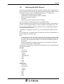
2.4.10
Tools Menu, Translation Support
The translation support function allows the user to export all text elements of a language so that they can be translated externally. The text is exported to a Unicode
file. This file can easily be imported and edited in any editor that supports Unicode
(such as Editor or Wordpad). When saving the file, make sure that 'text file' has been
selected as the file type and that Unicode is specified as the code type. After translation, you can import the text elements again.
Translation support applies to texts in:
–
Screens, subscreens, help screens, terminal messages, edit screens
–
Messages
–
Recipes
–
Text lists
2-19
Programming
Follow the steps below to export the text items of a language:
1. Select the language in the left column (project languages).
2. From the Edit menu select the menu item Export texts
3. Enter a storage location and a file name in the dialog that next appears and confirm with Save.
An output window displaying the current export status appears.
Once the export is complete, the directory path and file name of the export file are
shown in the Export file path names column of the Translation support window.
The display of the directories and file names indicates whether a language has already been translated.
The export file can be translated into another language using any text editor. Make
sure not to edit the first two lines in the file!
Translation support (import)
Translation support (export)
Managing multilingual applications
Structure of the export/import file
2.4.10.1
Translation Support, Export
Use this function to export all of the project text elements and translate them externally.
Follow the steps below to start the translation support tool, export function:
1. Select a language in the project tree.
2. From the Tools menu, select Translation support, Export texts.
The Save text elements of the language to a file dialog appears. You can change
the predefined path, which is saved for each specific language to the database. The
same path is proposed if you want to import the texts at a later stage.
3. Confirm with OK.
The output window appears. Any problems that have occurred during the export are
displayed here.
You can edit the ASCII file using any editor.
Make sure that the formatting is not damaged and that the first two lines and object
IDs are not changed.
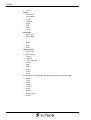
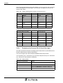
Structure of the ASCII file:
Column 1 = Object ID for the language
Column 2 = Membership
Column 3 = Horizontal position
Column 4 = Vertical position
Column 5 = Length
Column 6 = Font
Column 7 = Text
Each time an export file is created, a new identification code is created and also
stored in the database. A message is displayed to the user if the entries do not match
when the file is imported; the user can then either terminate or continue the import
process.
2-20
Programming
The following applies to the maximum length of the individual text types:
–
Static texts = Unlimited (<4096)
–
Message texts = Constant defined for message texts (currently 255)
–
Texts in text lists = Unlimited (<4096)
2.4.10.2
Translation Support, Import
Use this function to import texts that you have first exported and then translated.
Follow the steps below to start the translation support tool, import function:
1. Select a language in the project tree.
2. From the Tools menu, select Translation support, Import texts.
The Import text elements of the language from a file dialog appears. The same
path and file used for the export are proposed.
3. Confirm with OK.
2.4.11
Tools Menu, Import
Use this function to import variables from symbol files that you created while programming the controller. These variables are then transferred to the programming
software's variable list and can be used in programming.
You can also import text entries from external files. To do this, first select a text list
where you want to enter the texts.
2.4.11.1
Import, Variables from Symbol File
A variable list must be open before variables can be imported from a symbol file.
The programming software provides a function for importing symbol files from other
manufacturers. At present, the Bosch SXS format is supported (as of WINSPS 2.11):
To carry out the import, you require the protocol type/controller BUEP19E. Select this
as the active controller and open the variable list. Follow the steps below:
1. If necessary, create a new controller (BUEP19E).
2. Open the variable list editor.
3. The Tools/Import/Variables from symbol file menu item is now enabled; activate
it.
You can use the import function to perform the following tasks:
–
Fill an empty variable list
–
Compare existing variable list entries with the import file. In this case, you must
select the variable entries in the variable list for comparison. Only selected lines
are included in the comparison process. Any additional entries that are recognized at data read-in time as not yet created are then added to the variable list
(provided they were selected). This step occurs regardless of whether or not the
entries are already contained in the variable list.
2-21
Programming
2.4.11.2
Import, Variables from Symbol File, Step 1
The Symbols area allows you to import either all symbols (without restrictions) or only
symbols that contain the specified string. In this case, the SXS file is searched for
symbols with names that contain the specified character string.
The Default Access Mode area allows you to specify Byte or Word as the default access method.
The default access method is applied to all symbols whose access method can not
be clearly identified.
The Create Variable Name From area allows you to choose whether to create the
variable names on the basis of the symbolic name of the symbol, the symbol's comment or both.
Click Next to continue this procedure.
2.4.11.3
Import, Variables from Symbol File, Step 2
Select a symbol file. Use the Select button to search the computer's directory for the
symbol file that you want to open and import.
If the symbol file is in the same directory as the programming software, simply enter
the name of the symbol file in the input field.
Click Next to continue this procedure.
To return to the previous step, click Back.
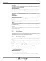
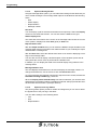
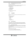
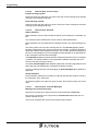
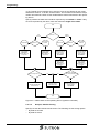
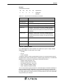
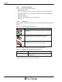
2.4.11.4
Import, Variables from Symbol File, Step 3
Step 3 lists all symbols that can be imported. A symbol is displayed to the left of each
entry in the list box. The symbols indicate the status of the entry.
Use the space bar to select or deselect the highlighted entry for the import process.
(This is a toggle function).
Complete the procedure with Finish.
To return to the previous step, click Back.
The data in the list are compared in one direction only. The comparison is always restricted to import data >> variable list data. For this reason, the status always refers
to the variable list entry.
2-22
Programming
2.4.11.5
Import, Text List Items from File
The programming software provides a function for generating text list items from
Bosch SXS files (WINSPS 2.11 or higher). This option is available in conjunction with
the BUEP19E and PROFIBUS-DP protocols.
To use the import function, you require a controller that supports the formats listed
above. First, activate this controller; then open the text list editor containing the text
list into which the import will take place. Follow the steps below:
1. If necessary, create a new controller that supports the required format. Now activate this controller.
2. Edit the text list to be imported into or create a new text list.
3. The Tools/Import/Text List Items from File menu item is now enabled; activate it.
You can use the import procedure to
–
Fill an empty text list.
–
Compare existing text list items with the import file. This requires you to select
the text list items (entries) to be compared. Only selected lines are included in
the comparison process. Any additional items that are recognized at data readin time as not yet created are added to the text list (provided they were selected).
The following options are available during an import process:
1. You can determine whether to import sequential function texts or operand texts.
2. You can determine whether to create only one item or whether to scan and generate the data from one specific file.
3. For sequential function texts: the number of items to be generated. There are two
fixed values and two automatically generated values for the number of items to
be created. The option From Directory Name (Automatically) creates 32 items,
provided the selected file is located in a subdirectory that identifies the controller
type CL200 in accordance with the WINSPS convention. Otherwise 64 items are
generated. With this option and the two fixed values, this number of items is generated even if the scanned file contains fewer items. In this case, a blank is generated as a text. The option From Data (Automatically) only generates the
number of items contained in the scanned data.
4. You can select a file or enter an address (using the Bosch syntax) and a description. If you wish to read from a file, you need an SXS file for sequential function
texts. The operand texts can only be generated from a cross-reference list file
that has been created using the WINSPS software version 2.11.
Once the data are scanned, all items are displayed in a list. A legend below the list
indicates whether the items are unchanged, new or modified. An arrow pointing upwards in the icon center indicates the items to be imported. Press the space bar to
highlight and select any items you do not want to import. The import arrow will disappear. If the space bar is pressed again, the import arrow will reappear.
Two additional items with the values 0 and 8224 are created when operand texts are
generated. In this case, the text consists of a blank.
2-23
Programming
2.4.11.6
Import, Importing into a Text List, Step 1
During step 1 of the import process, you should specify whether to import
–
Sequential function texts for diagnosis purposes in screens showing the sequential function status or
–
Operand texts for diagnostic purposes in screens showing sequential function diagnostic information.
The Number of Entries To Create area allows you to choose whether you want to create:
1. 32 entries
2. 64 entries
3. 32 entries automatically from the directory. For directories with fewer than 32 entries, the remaining entries are represented by blanks.
4. as many entries as possible automatically from the data.
In addition, you can decide to import the entire contents of a file or one line only.
Click Next > to continue this procedure.
2.4.11.7
Import, Importing into a Text List, Step 2
Importing from one line:
Enter the information using the Bosch syntax into the input fields of the Entry of a Single Address with Comment area.
Importing from a symbol file:
Select a symbol file. Use the Select button to search the computer's directory for the
symbol file that you want to open and import.
If the symbol file is in the same directory as the programming software, simply enter
the name of the symbol file in the input field.
Click Next > to continue this procedure.
To return to the previous step, click < Back.
2.4.11.8
Import, Importing into a Text List, Step 3
In the Length of symbolic description area, you can specifically limit the length of
the entry for import to a specific length or decide to ignore the symbolic identifier (description) during import.
By default, no limit applies to the length of the symbolic identifier during import.
In the Gap (character between symbol land comment) area, enter a character to be
inserted between the symbolic identifier and the comment to separate them visually.
If you do not enter a character, the identifier and comment are joined together.
The conditions that apply to the Length of comment area are the same as those
that apply to the symbolic identifier.
It is not necessary to specify additional settings when importing the contents of only
one line.
Click Next > to continue this procedure.
To return to the previous step, click < Back.
2-24
Programming
2.4.11.9
Import, Importing into a Text List, Step 4
Step 4 displays all importable symbols in a list. A symbol is displayed to the right of
each entry in the list box. The symbols indicate the status of the entry.
Use the space bar to select or deselect (toggle function) the highlighted entry for the
import procedure.
Complete the procedure with Finish. To return to the previous step, click < Back.
The data in the list are compared in one direction only. This comparison direction is
always: import data >> text list data. For this reason, the status always refers to the
text list entry.
2.4.12
Tools Menu, Export
Copy an image of the current window to the clipboard.
2.4.12.1
Export, Exporting the Window Contents
You can use the Export window contents function to copy an image of the current
window contents to the clipboard.
The data copied to the clipboard can then be used as required: for example, the obtained images can be inserted into a document.
This function can not be used to create a copy from an image because the data copied to the clipboard are in a bitmap format. For this purpose, use the function Copy/
Cut/Paste instead.
2.4.13
Tools Menu, Optimizing a Database
Frequent changes made to a project can result in unnecessary expansion of the
project database.
However, it is possible to optimize a database that has been extensively fragmented
in this way. Before doing so, ensure no project is open.
Before optimizing a database, you may want to create a backup of the database on
a secure data medium.
If a copy has not yet been created, you can terminate the procedure with the No button. Otherwise, start the procedure with the Yes button.
The process can not be stopped. If the computer crashes or becomes no longer operable for some reason while the optimizing procedure is running, the project database will be damaged.
Enter the name of the project database to be optimized in the dialog displayed and
confirm with OK.
2-25
Programming
2.5
Help Menu
The help for the programming software is context-sensitive. This means by pressing
the F1 key, a help topic related to the item hat has focus is invoked.
2.5.1
Help Menu, Contents
This menu item allows you to display help for the programming software. The Contents tab appears on the left-hand side.
On the Contents tab, you can navigate through the help topics just as you would with
any file browser (Explorer).
Chapters are displayed as books and single topics are displayed as pages.
To display a topic, simply click the corresponding page.
To print a chapter or a topic, select it and click the Print button. In the dialog that appears, specify whether you want to print the selected topic or print the selected topic
and all related subchapters.
2.5.2
Help Menu, Index
This menu item allows you to display help for the programming software. The Index
tab appears on the left-hand side.
Enter a keyword into the Index tab. All matching index entries are automatically listed
below the input box.
Double-click an index entry in the list to view the associated topic.
2.5.3
Help Menu, Browse
This menu item allows you to display help for the programming software. The Search
tab appears on the left-hand side.
Enter a keyword into the Search tab. If you click the List Topics button, the entire help
system is searched and all topics that include the keyword are listed below the input
box.
Double-click a topic in the list to view it.
2.5.4
Help Menu, About
Displays the software version level.
Please have this information on hand whenever you contact the hotline.
The Internet: www.suetron.de button brings you to the homepage of Sütron electronic.
By clicking the File list button, you obtain a list of all programming software files installed.
2-26
Programming
2.5.5
Help Menu, Sütron Homepage
This menu item opens your default Internet browser and the homepage of Sütron
electronic is automatically loaded.
2.5.6
Help Menu, Netviewer
This menu item starts the Netviewer software. This software provides the support
person the following capabilities enabling him to better assist you:
–
The support person can see your screen contents.
–
The support person can use a flashing pointer to draw your attention to a particular item on your screen.
–
The support person can remotely control your PC.
–
The support person is capable of exchanging files with you.
–
You can see the screen contents of the support person.
In the start dialog, enter a support person number which is given to you by telephone
by the support person. Next, a dialog appears where you can grant/revoke data
transfer, screen display and remote control rights.
2.5.7
Help Menu, Tip Of The Day
This menu item opens the Tip of the day dialog. This dialog presents you helpful tips
on the software each time the programming software is started.
2-27
Programming
2.6
Terminal Type
A project is always created on the basis of a terminal type. This means that parameters such as display size, number of function keys and so on, are predefined in advance.
However, you can also port a project to another terminal type, taking into account any
restrictions due to the changed hardware conditions.
Based on the terminal type, you can create a project by creating contents in the
project tree branches and defining parameters.
Table 2-3
Project tree contents
Branch
Contents
Communication
Parameters for the interfaces on the PC and
on the operating device.
Parameters for the protocols used by the operating device to communicate with controllers.
Controller variables
Languages
Screens, function keys, messages, recipes,
print logs, text lists
User management
Passwords
Script management
Scripts and script variables
Supplementary functions
Parameters for the polling area, date & time,
running time meters, Unicode, status information, date input options, screen saver
Resources
Symbols, images, image lists
Project management
Projects with startup language, project languages, project controller
2.6.1
Terminal Type, Change
If you want to port a project from one terminal type to another, select the required
terminal from the Type field.
Depending on the model, you can select one of the procedures below for grayscale
display.
–
16
–
8
–
4
–
4 + Dithering
2.6.2
Terminal Type, Memory Size
Select the appropriate memory size for operating devices with different memory capabilities.
2-28
Programming
2.6.3
Terminal Type, Touch Parameters
You can define the following default settings for touch-sensitive terminals:
Default sound:
This is the default setting for the signal tone that sounds when the button is pressed.
The following options are available:
–
No beep (no sound)
–
Beep when pressed (sound for press touch)
–
Beep when released (sound for release touch)
–
Beep when pressed and released (sound for press and release)
–
Continuous tone while pressed (sound during press touch)
Enter the duration of the beep in seconds under Time.
Default Image for System Icon:
Enter the image to be displayed if a system icon is not available.
See chapter “System Icon“ on page 3-124.
2.6.4
Terminal Type, Color Palette
You can change the color combination used in operating devices that can display
grayscale or color. The changed color combinations are then available throughout
the project.
The list has two columns: color 1 and color 2.
Since an element is usually displayed with one color, color 1 and color 2 are identical
in this case. If you have a flashing element, you must use a color combination where
color 1 is not the same as color 2. The color of the element then changes from one
color to the other.
Use the numerical values for Red, Green and Blue to combine new colors or edit existing colors.
The color combinations with the number 16 to 63 are supplied for flashing elements.
The default flashing frequency is 1 Hz.
2.6.5
Terminal Type, Fonts
Any WINDOWS fonts can be used for programming purposes. You must however
specify the fonts in advance.
Each font specified is listed with its font size (in points) and font style (bold or italic).
Text elements of the project are linked to the font name listed. If you change the font
or only an attribute of a font by clicking Edit font it affects all corresponding text elements of the project.
2-29
Programming
2.6.6
Terminal Type, Terminal Orientation
Check the checkbox Twisted by 180° to represent the screens upside-down.
This setting is only valid for operating devices with touch screen which have a display
that allows twisting the representation by 180°!
2.7
Comment
You can enter comments of any length about the database created.
Example of some useful details you might include:
–
Database version
–
Last changed on (date)
–
Database created by (name)
–
Machines and machine variants for which the project has been created.
2.8
Demomode
Check the checkbox Demomode to create a project which supports testing the operating device without having a controller connected.
Translate the project with this setting and download the project to the operating device. Start the operating device again if it doesn’t boot automatically.
During the boot process the text DEMOMODE is displayed for two seconds.
Without a controller no realistic values are displayed. The entered values are not
saved.
Please check
–
the navigation,
–
the function of the keys or buttons,
–
the input editors,
–
the script performance,
–
the design of the project.
To operate the operating device in standard mode uncheck the checkbox Demomode and compile the project once again. Download the project into the operating
device. After download is complete the operating device reboots automatically and
operates in standard mode.
2-30
Programming
2.9
Communication
The operating device can communicate with the PC, a controller, a logging printer or
a scanner.
To add a controller as a communication partner to the project, follow the steps below:
1. Right-click with the mouse on the Communication branch.
2. Select New controller from the menu.
The Protocol selection dialog opens.
3. Select the name of a controller.
4. Confirm with OK.
The Create controllers dialog appears.
5. Enter a new name, if necessary.
6. Confirm with OK.
The name of the controller is added as an element in the Communication branch.
2.9.1
Protocol Selection
Choose the protocol that you want to use for your project to exchange data between
the operating device and PLC.
For this purpose, select the name of the protocol to be used and confirm with OK.
The next dialog allows you to assign another name to the selected protocol; that is,
the name to be displayed for the protocol in the list box of the Controllers tab.
To ensure smooth exchange of data between the PLC and the operating device, you
must define the protocol parameters.
In addition, you need to create a system of allocation (in the variable list) between
the variables, their addresses and the type of data.
The type of addressing used depends on the PLC.
2.9.2
PC >> Terminal
This function is available for all terminals with an SER2 serial interface.
Define identical communication parameters on both ends.
You can exchange the following information by means of this connection:
–
Recipes
–
Data sets
–
Terminal files
2.9.2.1
PC >> Terminal, Enable Transfer
By selecting the Enable automatic download check box, you instruct the operating
device to recognize and start a download automatically. This also applies to the Enable automatic upload check box.
2-31
Programming
2.9.2.2
PC >> Terminal, Interface Parameters
The interface parameters defined for the connection between the PC and terminal
influence the download process.
First, select the COM interface whose values you wish to change.
The Interface Parameters area contains default values. To change those values,
simply select other values from the appropriate lists.
The default values can be restored at any time. To restore the values, click the Default Values button.
To adopt the interface parameters from the S3 file belonging to the compiled project,
click the S3 File button.
The PC interface is set up with these default values.
Table 2-4
Default settings for the RS232 interface
Parameter
Value
Baud rate
19200 Baud
Parity
Odd
Data bits
7
Stop bits
1
Handshake
Software handshake
Port (interface)
COM2
2.9.3
Terminal >> Printer & Scanner
This function is available for all operating devices with an SER2 serial interface. Operating devices with Windows CE operating system only use the USB interface for
printing.
Define the communication parameters required to connect the operating device with
a logging printer or a scanner.
See chapter “Working with Scanners“ on page 3-170.
2-32
Programming
2.9.3.1
Terminal >> Printer& Scanner, Interface Parameters
The operating device is equipped with an RS232 interface. This interface is used to
connect the device with a logging printer or a scanner.
The interface uses default values when the programming system is started for the
first time.
Table 2-5
Default settings for the RS232 interface
Parameter
Value
Baud rate
19200 Baud
Parity
Odd
Data bits
7
Stop bits
1
Handshake
Software handshake
2.9.3.2
Terminal >> Printer & Scanner, Scanner Parameters
Scanner extension:
To run a scanner on the SER2 interface of the operating device, you must first activate the use option for scanner parameters.
Scanner parameters:
Enter the default and initialization parameters. These parameters initialize the scanner and define the specific data transfer information.
In the Default field, enter an ASCII string that activates the scanner.
In the Initialization field, enter an ASCII string that configures the scanner.
The parameters entered can not be validated since you can not select a specific
scanner type.
You can connect any scanner with an RS232 interface that transmits ASCII
characters.
Scanner <--> Terminal protocol:
Press Transfer data with ENTER key (Data take-over with ENTER key) if you want
to press the Enter key every time a bar code is scanned, in order to enter the data.
If you are using a scanner that requires confirmation of receipt once the scanned
value has been transferred, activate the Terminal sends ACK signal following receipt (Terminal sends ACK after receive data) function.
To allow the terminal to recognize when a scanned value begins and ends, enter the
characters sent by the scanner beforehand and afterward as the data prefix and
data postfix.
2-33
Programming
2.9.3.3
Terminal >> Printer & Scanner, Unicode
For printer control, the characters intended for output must be converted according
to a conversion table. Characters that are not contained in the conversion table are
not printed.
Three recognized character tables are used worldwide.
–
European standard
–
GB2312-80
–
GB18030
Choose the character table for your requirements by selecting the relevant radio button from the Printer standard area.
In the Language switching area, you can enter a string in the Activation code
area. This string is sent to the printer in order to activate the correct character set before every print operation.
Refer to the printer's user guide for information on entering the correct activation
code.
Example:
–
Switch to GB2312-80 character set = FS & (Hex: 1C 26)
–
Switch to European standard = FS. (Hex: 1C 2E)
In China, the built-in standard code type is used. The table below shows the difference between this character set and GB2312-80:
Table 2-6
Conversion table for the built-in standard character set
Unicode
GB2312-80
Built-in standard
0x3000
0x2121
0xA1A1
0x5509
0x3026
0xB0A6
0x54C0
0x3027
0xB0A7
0x7691
0x3028
0xB0A8
0x9F44
0x777E
0xF7FE
... 0xH
0xL 0x(H+0x80)
0x(L+0x80)
2.9.4
Protocol, Loop-through Operation
Using loop-through operation, you can link the programming unit to the operating device that connects through the signals to the controller.
If you are using the BRC-Symbolic protocol, loop-through operation allows automatic
recognition of the programming unit. With point-to-point connections, you must activate/deactivate and monitor loop-through operation using system variables.
While loop-through mode is activated, the terminal's COM1 interface can not be used
for other applications (such as a scanner, printer, transfer of recipe data sets).
See chapter “Loop-through Operation“ on page 3-97.
2-34
Programming
2.9.5
Encoding of Alphanumerical Strings
Text character identification:
For alphanumeric strings read by the operating device from the controller, you must
specify the standard code to be used to interpret the characters.
For 8-bit characters:
–
ISO 8859-1 (Latin-1)
–
IBM OEM CP437
–
ANSI (MS Windows)
For 16-bit characters:
–
16-bit Unicode
For characters of variable bit length:
–
Unicode UTF-8
2.10
Languages
The Languages category combines all of the elements that belong to a national language.
The elements are as follows:
–
Global function keys
–
Message system
–
Recipes
–
Print log
–
Subprint logs
–
Language resources
2.10.1
System Defaults
In system defaults, you define parameters that are valid for the current language.
Starting with the number for the current language, you can set specific fonts to be
used for texts, the screen displayed at the start of the user interface and much more.
2.10.1.1
System Defaults, Identifier
In the Language number area, you can specify a number for the current language
in the range of 1 to 16. You will reuse this language number if you create a language
selection using a text list.
These settings you can assign a number for the customer version to serve as a reference.
The valid range of values is 0 to 255.
The value is saved in the UserVersion system variable.
You can output this system variable in any input/output screen.
2-35
Programming
There is no other functional link in the operating device. You can not change the
value in the operating device.
See chapter “UserVersion“ on page 3-56.
2.10.1.2
System Defaults, Base Screens
Within a project, you have five screens whose functions differ from a standard screen
for input and output.
Startup:
The startup screen is the first one displayed after the electrical supply to the operating device is switched on. It is only displayed for 5 seconds. During this time, all LEDs
on the operating device are turned on so that they can be checked for proper functioning. The operating device then switches to the main screen. If you press the Enter
key or Setup button while the startup screen is displayed, the operating device
switches to the setup screen.
Setup:
You can only access the setup screen if you press the Enter key or the Setup button
during the initialization phase (the startup screen is displayed for five seconds).
On the setup screen, it may be useful to include the following functions:
–
Activate/deactivate download function
–
Set protocol parameters
–
Select PLC protocol
–
Set date and time
–
Display firmware level of the operating device
If you program these functions using system variables, the operator can select the
corresponding parameter from text lists.
Password:
If you wish to use the same screen for each password query, create a password
screen and specify its name here.
It may be useful to allow all function keys go to the main screen so that the operator
does not get stuck on the password screen.
Main:
The main screen is always displayed after the initialization phase has been completed.
The user interface must start from here. Starting from this screen, branches can be
created to all other screens. The main screen can contain all of the elements of a
standard input/output screen.
Default help:
The default help screen is always displayed if no specific help screen has been set
up for the current screen. It is also displayed if no help screen is available for the variable and current screen.
2-36
Programming
2.10.1.3
System Defaults, Standard Format
You have the option to select a font for the current language so that language-specific characters can be displayed. This font is used as the standard font for all texts
you input during programming.
Fonts selected in Options can disable this setting for representation in various editors.
2.10.1.4
System Defaults, Reference Screen
In the Time-controlled target area, you can specify a base screen that is displayed
if the operating device is not used for a set period of time.
You can choose all of the user interface screens as the base screen with the exception of the following:
–
Startup screen
–
Setup screen
–
Password screen
In the base screen, note that you may need to reactivate password protection. Enter
a value between 10 sec. and 9999 sec. for the time.
2.10.2
Screens
Screens refer to the contents of a page on the operating device display. This means
that screens vary in size, depending on the operating device being used.
You can display and enter texts and variables (250) in screens.
You can define the layout of these screens and use images to customize them to
your own specific needs. To display basic elements that are identical in every screen,
you can create these elements in subscreens and link the subscreens with screens.
For each screen, you can program specific softkeys or function keys to allow you to
jump to other screens. You can also program cursor keys to open other screens.
Furthermore, you can use the function keys to change variable values.
If you use the same screen names in all languages, you can use global screen elements to design similar screens. Global screen elements (for example, global variables) appear in each screen with the same name.
2.10.2.1
Screen, General
The general parameters for a screen are divided into the following areas:
–
Number
–
Value of the ScreenOffset system variable
–
Options
Number:
Each screen of a project has a unique number. If you do not enter a number, the next
consecutive number is automatically assigned.
You can use the screen number to carry out the following for screens:
–
Enter screens in a text list and display as a screen menu
–
Switch screens over from the controller
–
Write documentation for screens
2-37
Programming
Value of the ScreenOffset variable:
Enter a value to be used to multiplex controller variables.
If a screen is called up with screen offset, the offset value is entered in the
ScreenOffset system variable. At run time, the offset value is added to the address
of a controller variable in this screen that is multiplexed with the ScreenOffset system variable.
Example:
If the screen offset is 20 and the basic address of the controller variable to be multiplexed is MW100, the result is a controller address of MW120 when the screen is
called up.
Options area:
Choose the direction in which the next variable is accessed when you press the Enter
key after editing a variable value.
Activate automatic data release if you wish to have the option to edit variable values
immediately after changing to the current screen. Otherwise, you will need to press
the Data Release key.
Automatic data release can not be used with operating devices that use a touch
screen.
See chapter “ScreenOffset“ on page 3-109.
2.10.2.2
Screen, Password-Protection
The parameters to password-protect a screen are divided into the following areas:
–
Access level
–
Reset password
Access Level area:
The access level corresponds to a threshold value for password management. You
use it to determine if and when operators must enter a password.
Table 2-7
Access level
Configurable Values
Default Value
0 to 255
0
The initial access level default value for each screen is 0. This corresponds to the
status general release.
If the threshold value is above the view level, the operator can only display this
screen by entering the correct password.
If the threshold value is above the edit level, the operator can only change the variables contained in the screen by entering the correct password.
Reset Password area:
If you activate the Reset Password parameter, password-protection is reactivated after you exit this screen. If you return to this screen, you must enter your password
again.
2-38
Programming
2.10.2.3
Screen, Help Screen
You can create a specific help screen for each screen and display it by selecting the
Help key, a corresponding button or clicking a free area of the display background.
If you wish to provide a help screen for the current screen, select an existing help
screen.
You can not use the Activate help screen parameter for operating devices equipped
with a keyboard. You activate a free area of the display background to call up the help
screen.
2.10.2.4
Screen, Background Color
For each screen, you can select a separate color for the entire screen area. All elements that may be contained in a screen cover over the background color!
You can only use this parameter for operating devices that use gray scales or color
display.
2.10.2.5
Screen, Script Parameters
At the same time a screen is displayed, you can execute a script. Enter the name of
the script in the Display script field.
2.10.2.6
Screen, Function Keys
You can redefine the functions of the keys (function keys and special function keys)
for each screen. Keys defined for one screen specifically are also referred to as softkeys.
The specific function of a key within a screen takes precedence over the global function assigned to the same key.
Possible definitions are as listed below:
–
Direct jump to screen
–
Indirect jump to screen (Screen reference list required)
–
Write a value to a variable (0 to 255) when a key is pressed
–
Write a value to a variable (0 to 255) when a key is released
Direct jump to screen:
Setting up a function key to call up a screen directly allows the operator to access a
specified screen quickly by simply pressing this function key. The authorization to access the screen is checked by the password management function; if necessary, a
password screen is displayed first. In this case, a valid password must be entered
before the screen is called up.
Indirect jump to screen:
The controller can effect an indirect jump to a screen. The operator always presses
the same function key. At run time, the controller writes a value to the variable for
screen reference control. The operating device reads this value and compares it to
the values in the screen reference list. The screen that is assigned the corresponding
value in the screen reference list is then accessed.
Follow the steps below to jump to a screen indirectly:
–
Create a screen reference list
–
Define a transfer variable
–
Specify a screen reference list in the function key table.
2-39
Programming
2.10.2.7
Linking with Screen
First decide whether the operator should be able to press a key and jump to a screen
directly or whether he/she should switch to a screen whose number can be controlled
by the PLC.
All of the screens already created are available in a list for direct selection.
Follow the steps below to select a screen for direct screen change:
1. Select a field from the Screen column.
2. Select Edit from the context menu.
3. Select the Reference to screen (direct) selection button.
4. Select the required screen from the list.
5. Confirm with OK.
The name is then entered in the table field.
To select screens indirectly, you must first create screen reference lists. Screen reference lists already created are provided in a list.
Follow the steps below to select a screen reference list for an indirect screen change:
1. Select a field from the Screen column.
2. Select Edit from the context menu.
3. Select the Reference to screen list (indirect) selection button.
4. Select the name of the required screen reference list in the list.
5. Confirm with OK.
The name is then entered in the table field.
2.10.2.8
Linking with Variable
Follow the steps below to select a variable name:
1. In the Press variable or Release variable column, select a field.
2. Select Edit from the context menu.
3. In the dialog box that opens, select the name of the required variable.
4. Confirm with OK.
The name is then entered in the table field. To transfer a variable value to the controller only for the time the key remains pressed, select the same variable name for
the release variable and enter a value of 0 (zero) for this action.
2-40
Programming
2.10.2.9
Linked Subscreens
Subscreens are linked to screens to ensure screen elements are identical and always appear in the same positions. This allows you to standardize the design of the
project.
The left list box displays all of the existing subscreens.
The right list box shows all of the subscreens linked to the current screen.
You can use the buttons in-between to perform the following actions:
> Adds the selected subscreen to the linked subscreens. A subscreen can be added
only once.
>> Adds all of the listed subscreens to the linked subscreens.
< Removes the selected subscreen from the list of linked subscreens.
<< Removes all of the subscreens from the list of linked subscreens.
Complete your entry with OK to return to the previously used function.
2.10.2.10
Screen Background Color
Static text and variable screen elements can be displayed in different color combinations. The selected screen element is assigned a background and foreground color
from the list for this purpose.
Select the screen element and choose Parameters screen element from the context menu.
The list has two columns: color 1 and color 2.
The background for the screen element is generally displayed in color 1. For the
background to flash, a different color must be selected for color 2. The background
color then switches to and from one color to the other. If color 2 is now the same as
the foreground color, it creates the impression that the element is being switched on
and off.
2.10.3
Subscreens
Subscreens are used to ensure a consistent design across all screens containing the
same elements. To achieve this, you define a subscreen which contains the required
elements, and then link it to each of the screens that are supposed to have the same
design.
Subscreens can contain all the elements of a standard screen with the exception of
tables, recipe and message fields.
When compiled, the screen and linked subscreens are joined to become one resulting screen.
2.10.4
Help Screens
To optimize usability, you can create a help screen for each screen and each input
variable. To call up this help on the operating device, press the Help key, a button
that has been programmed for this purpose or click a free area of the display background.
If data release is not requested, a help text appears for the screen. The help text for
the variable that is currently selected appears, provided the editor for entering a variable value has been activated.
2-41
Programming
The default help screen appears if no specific help screen has been linked to a
screen or a variable.
A help screen is the same size as a standard screen. You can enter static texts, background images, output variables and tables in a help screen. To ensure consistent
design, help screens can also be linked to subscreens.
2.10.4.1
Default Help Screen
The default help screen is always displayed if you have not linked any help screen to
the screen or input variable. The default help screen is always available and only displays a blank page if it is not programmed.
2.10.4.2
Help Screen, Background Color
You can select a background color or color combination for the background of a
screen.
A color combination comprises color 1 and color 2.
Color 1 means that the background usually has this color.
Color 2 means that the background alternates between color 1 and 2 in flash mode.
Selecting contrasting colors for color 1 and color 2, e.g. no. 17 for the background
and no. 16 for the foreground, will ensure that the element remains legible when
flashing.
However, if you select color no. 1 for the background and color no. 16 for the foreground, the element will 'disappear' when it is flashing.
2.10.5
Global Function Keys
Global function keys can perform a function from any part of the project. Any settings
defined for global keys apply to screens only if no other functions have been assigned to the keys within that screen.
Possible functions are listed below:
2-42
1.
Jump to a screen
2.
Transfer variable value when a key is pressed
3.
Transfer variable value when a key is released
4.
Activate the LED in a function key when a message has been received from the
serial or parallel message system
Programming
2.10.6
Message System
The message system is an integral part of the user interface. Messages are reactions
to events that are communicated to the operator in an intelligible form. A distinction
is made between internally and externally generated messages, depending on
where the event occurred. The diagram below shows the structure of the message
system.
Message system
Internal messages
Figure 2-4
External messages
Terminal messages
Serial message
system
Error messages
Parallel message
system
Structure of the messages system
The areas shown in gray color can be freely designed during programming.
2.10.6.1
Messages
The message editor assigns texts to message numbers that may be transmitted from
the PLC to the operating device.
Messages are distinguished by their priority. The priority is determined by a combination of message number and message group where the following applies:
The lower the message number and group number, the higher the message priority.
Messages can be created on the basis of the following specifications:
–
A maximum of 3000 messages
–
A maximum of 8 message groups
–
A maximum of 255 characters per message
–
A maximum of 2 variables per message
–
A maximum of 255 line breaks per message
The message editor is in tabular form.
The table consists of two columns allowing you to enter the message numbers and
message contents.
For automatic assignment of numbers to messages, the appropriate check box must
be selected, in the Message Editor options dialog. Existing messages can automatically be numbered consecutively later.
A scale is displayed above the column for the message contents. The scale is displayed with Pixel or Grid as the unit depending on the setting in the message editor
options dialog.
2-43
Programming
Any text can be entered in the column for the message contents. Up to two output
variables and up to 255 line breaks can also be included in the message. Line breaks
are displayed within the row as a gray rectangular. Every line break counts as a message character, thereby reducing the total number of displayable characters for the
message.
Within the input field of the message editor, marks indicate the width of the display
of the selected operating device. The marks can be activated or deactivated in the
message editor options dialog.
The messages can be displayed on the operating device with the font defined for the
message field. This font can be selected freely depending on the operating device
type.
The font used to display the message numbers in the message editor can be
changed individually in the Tools menu, Options menu item, Message editor tab.
Any of the Windows fonts can be selected.
You can either display all of the messages in the message field of a screen or display
them individually using the system variables.
Any messages received are acknowledged with either the Acknowledge special key
or a function key. The function key must control the value of the RepmanQuitKey
system variable.
2.10.6.1.1
Import Messages from a Message File
To call this feature click on the item Message system with the right mouse button and
select the identically named menu item form the context menu.
Select a file which must have the following structure:
Message number_1;“Message text 1“
Message number_2;“Message text 2“
Message number_n;“Message text n“
Check the check box delete already existing messages if they do not exist in the
message file, if you import the same message file again, but with less messages in
it and you want these messages to be deleted in the message system, too.
To import the messages with a message number + offset, enter a value for offset for
message numbers from the message file.
At the import only messages are taken into account with numbers from 1 to 9000.
2.10.6.1.2
Message Parameters
Colors:
Displays the background color and foreground color assigned to the message. These
colors are used to display the message on the operating device.
To replace with other colors, click Assign.
The setting can be viewed immediately after you return to the message.
Screen change:
If a message is called up, a screen of the operator's choice can be called up at the
same time.
The screen does not have to be called up immediately when the message is received, but can be called up once a message is selected within the message field.
2-44
Programming
–
Screen change on arrival of message:
If the controller transmits a message, the operating device automatically changes
to the specified screen. You can select any screen here. The parameter when a
message arrives does not apply to screen changes that have been enforced by
the controller. Furthermore, the screen accessed does not necessarily have the
same number as the message.
–
Screen change within the message screen:
Once messages arrived have been displayed in a screen's message field, the top
message is indicated by the > cursor arrow. You can select other messages using the Cursor Up and Cursor Down keys. You can activate the RepmanChgScreen system variable to effect a screen change to the screen of your choice
according to the settings for the message. This parameter can therefore be used
to design a message-based user interface. It allows you to access screens faster, which contain more detailed information on the message in question, to allow
particular settings etc.
Help screen:
The help screen the operator can call up for message management can be specified
in the Help Screen area.
Group:
The message entered previously can be assigned to a group (1 to 8).
The messages can then be displayed in different message screens in accordance
with the established groups.
Advantages:
–
Further classification of messages (e.g. according to the area of the plant)
–
Further classification of messages according to priority
–
New assignment option for parallel messages
For serial message channel:
–
Simultaneous screen change and message transfer: (Simultaneous screen
change and message call)
If this check box is selected, a screen change takes place at the same time as
the message transfer and the message is stored in the serial message memory.
This only applies to messages transmitted by the serial message channel and
messages to which 8000H was previously added.
Example: The value 800AH is written to the serial message channel.
In this case, screen number 10 is called up and the message with the number 10
assigned is stored in the serial message memory.
Transfer from the parallel to serial message memory: (Put message from parallel
to serial message memory)
–
Store in ser. message memory:
Messages of the parallel message system can be stored in the memory for serial
messages. This allows parallel messages to be captured that appear for a short
time only. You can also capture the moment messages appear and disappear
using the arrived/departed status identifiers.
2-45
Programming
–
With appear/disappear status:
Messages with this parameter are identified by a status attribute at the start of
the entire message text.
The following letters are provided to identify the status. You can, however, replace them with other letters. The letters are assigned to the relevant language
so that you can choose different letters for each language.
K = Appears
G = Disappears
Q = To be acknowledged
q = Acknowledged.
–
Automatically clear appear/disappear:
A message of the parallel message system with this parameter is stored in the
memory for serial messages when it appears. The message is first labeled with
the Arrived (appear) status here.
Once the parallel message is no longer active, it is removed from the serial message memory once again.
–
Acknowledgment of message:
You can acknowledge messages with this parameter that have been stored in
the memory for serial messages.
Acknowledged messages are then labeled with the Acknowledged identifier.
To acknowledge messages, you require the Acknowledge key, a function key
which controls the RepmanQuitKey system variable, or a relevant button.
Printing the message in the serial message memory:
–
Automatic print of message:
With this parameter, a message which reaches the operating device is not only
displayed in the message field but also printed.
You must select this parameter separately for each individual message which
should be printed directly.
A further requirement for automatic printing is that the RepmanRepPrint system
variable be set to 1.
–
Automatic clear of the message after printing:
Messages with this parameter are deleted from the serial message memory immediately after they are printed on the logging printer.
A further requirement for automatic printing is that the RepmanRepPrint system
variable be set to 1.
–
Automatic print after acknowledgement:
Messages with this parameter are output on the printer immediately after they
have been acknowledged.
A further requirement for automatic printing is that the RepmanRepPrint system
variable be set to 1.
2.10.6.1.3
Foreground and Background Color of the Message
Allows you to assign the background and foreground color combination to a message.
The setting can be viewed immediately after you return to the message.
2.10.6.1.4
Font for Editing Messages
Select a font to be used when you create or edit messages in the Messages window.
To save a new font in the list of fonts available for selection, click the New font button.
The selected font only applies when messages are displayed within the programming
software, not on the operating device.
2-46
Programming
2.10.6.2
Controller Area, Activate Messages
Representation (option):
Select either reduced or extended representation of the parallel message system.
With the reduced representation you define the parallel message system with start
address, size and polling time.
With the extended representation you define up to 8 sections of the parallel message
system with start address, acknowledge areas, sizes, offsets, starts of message areas and ends of message areas.
Parallel message system
For the parallel message system, you must enter a starting address of the data area
where the messages are stored in the controller in bit-coded form.
You specify the number of bytes to define the size of the area for the status messages in the controller.
You can specify a maximum of 256 bytes for this area.
By entering the polling time, you specify the interval at which the operating device
reads the status messages' data area from the controller.
You can enter values from 0 to 25.5 seconds for the polling time.
The active messages are displayed in a screen with a message field for parallel messages. The status messages can be sorted according to various criteria.
2.10.6.3
Controller Area, Options
Parallel message system:
You specify a name for a variable with the same size as the variable for status messages in the field start address acknowledgement area.
Serial message system:
From the controller, you can delete all acknowledged messages if you write the bit
pattern E216h to the controller address Delete variable to messages and write the
control code 7FF5h to the serial message channel.
If you want to delete all messages, you need to write the control code 7FFEh to the
serial message channel. If you want to use this function of the operating device, you
must assign a 'variable for deleting messages'.
2.10.6.4
Terminal Area, Memory & Message
General parameters:
You can enter a message number to display a message directly (direct representation). The message number also indicates its priority. The lowest message number has the highest priority and the highest message number has the lowest priority.
All messages that have a higher priority than the message number specified here are
handled using a special procedure in the operating device when they appear. These
messages are indicated by the status LED flashing in the direct selection key of the
message screen or are signaled by a terminal message.
Using the Size of message buffer, you define how many messages can be stored
in the operating device. Specify the maximum number of messages to be managed
by the operating device.
2-47
Programming
2.10.6.5
Terminal Area, Function Keys
Parallel message system
Select a function key with which you wish to have the current message of the parallel
message system displayed directly.
Serial message system:
Select a function key with which you wish to have the current message of the serial
message system displayed directly.
2.10.6.6
Terminal Area, Identifier
Status identifiers
Status identifiers can be used to reflect the status of a message in the message system.
Any character of the standard font can be used for status identification.
Status identifiers are only appended to messages stored in the serial message system.
The history starts at the time the message arrives. The Arrived (appears) status
identifier is appended to the most recently arrived message. This status identifier is
appended to both serial and parallel messages. In the case of parallel messages that
have to be acknowledged, the Arrived (appears) status identifier is not appended until the messages have been acknowledged.
The Departed (disappears) status identifier marks the point of time when a message
is cleared. This status identifier is only appended to parallel messages that were
stored in the serial message memory.
The To be acknowledged status identifier (rather than Arrived) is appended to messages with the Acknowledgment of Message parameter enabled.
Once the message has been acknowledged, the Acknowledged status identifier is
appended.
Group identifiers:
Group identifiers classify the messages in 8 groups And thereby assign a priority to
the messages, at the same time.
The following applies: the higher the group number, the lower the priority of the message.
2.10.6.7
Terminal Area, Terminal Messages
Messages for terminal messages:
Specify the message to be output when the terminal indicates a fatal error.
Also specify a message to be output when a communication error with the connected controller occurs.
These error messages are stored in the serial message system.
2-48
Programming
2.10.6.8
Output Format, Status
General parameters:
You can have the messages displayed in indented format. To do so, specify the number of characters by which the lines are to be indented after the first line. The value
you enter here refers only to the display of messages in the operating device's message field.
Message sorting:
Messages can be sorted for output. You can use the corresponding radio button in
the Message Sorting area to define the sort criterion.
Using the corresponding check boxes in the representation of message area, you
can mark which parameters of a message are also output. The parameters can be
combined in any way.
Sort by time, newest first:
With this sorting order, the message that arrived last in the serial message memory
appears at the top of the message field.
Sort by time, oldest first:
With this sorting order, the message that arrived first in the serial message memory
appears at the top of the message field.
Sort by priority: If messages are sorted by priority, they are sorted in the message
field in such a way that the message with the highest priority is at the top and the
messages below are listed according to descending priority.
The lower the message number, the higher the message priority.
Sort by group:
With this sorting order, the message that has the lowest group number appears at
the top of the message field. If several messages belonging to the same group are
listed, they are sorted according to time, with the newest ones first.
Message representation:
Representation with message group:
The system outputs the group identifier before the message text.
Representation with message number:
The system outputs the message number before the message text.
Representation with message date:
The system outputs today’s date before the message text. In the date, the year can
either be output as two digits or four digits. The value of the date is frozen with the
message.
Representation with message time:
The system outputs the time before the message text. The value of the time is frozen
with the message.
2-49
Programming
2.10.6.9
Output Format, Recording
General parameters:
You can have the messages displayed in indented format. To do so, specify the number of characters by which the lines are to be indented after the first line. The value
you enter here refers only to the display of messages in the operating device's message field.
Message sorting:
Messages can be sorted for output. You can use the corresponding radio button in
the Message Sorting area to define the sort criterion.
Using the corresponding check boxes in the representation of message area, you
can mark which parameters of a message are also output. The parameters can be
combined in any way.
Sort by time, newest first:
With this sorting order, the message that arrived last in the serial message memory
appears at the top of the message field.
Activate this sorting if you like to print out the messages online.
Sort by time, oldest first:
With this sorting order, the message that arrived first in the serial message memory
appears at the top of the message field.
Activate this sorting if you like to print out the messages online.
Sort by priority: If messages are sorted by priority, they are sorted in the message
field in such a way that the message with the highest priority is at the top and the
messages below are listed according to descending priority.
The lower the message number, the higher the message priority.
Sort by group:
With this sorting order, the message that has the lowest group number appears at
the top of the message field. If several messages belonging to the same group are
listed, they are sorted according to time, with the newest ones first.
Sort by acknowledge status, unacknowledged first:
This sorting brings the unacknowledged messages to the top of the message field.
Message representation:
Representation with message group:
The system outputs the group identifier before the message text.
Representation with message number:
The system outputs the message number before the message text.
Representation with message date:
The system outputs today’s date before the message text. In the date, the year can
either be output as two digits or four digits. The value of the date is frozen with the
message.
Representation with message time:
The system outputs the time before the message text. The value of the time is frozen
with the message.
2-50
Programming
2.10.6.10
Output Format, Printer
Printer:
You can have the messages printed in indented format. To do so, specify the number
of characters by which the lines are to be indented after the first line. The value you
enter here refers only to printing messages on a logging printer.
You can choose from the following variants for outputting to the printer.
1. No output.
2. Formatted message - message output with preset formatting parameters.
3. Entire message - entire message output.
Indention (in characters):
The messages will be printed in indented format by the number of characters entered
here.
Number of messages per page:
Define how many messages shall be printed on one page. Especially USB printer
can only print out page by page. The operating device collects as many messages
as you assign and then starts printing them all together.
The less messages shall be printed on one page the faster is the reaction of the
printer on message events.
2.10.7
Recipes
You can set parameters in the following categories for every recipe:
–
Transfer active
–
Data set transfer from the terminal
–
Data set transfer to the terminal
–
Data set sorting
The recipes editor is divided into two halves. You have a view on the left similar to a
screen. This section allows you to enter the static texts (e.g. item names and units)
and variables specific to a particular recipe. You enter the variable values stored in
a data set in the right-hand section of the editor.
Controller:
The data set is controller-specific. You must therefore select the name of the controller from a list.
Variable offset:
You must assign an offset to every variable in a data set. This offset is used to store
the data in the operating device memory.
Example:
You should specify offsets for 4 variables in a data set.
Variable 1 = Byte variable
Variable 2 = Word variable
Variable 3 = Double-word variable
Variable 4 = Byte variable
2-51
Programming
The offsets are as follows:
Variable 1 = Offset 0
Variable 2 = Offset 1
Variable 3 = Offset 3
Variable 4 = Offset 7
Data set name:
In the Data Set Name column, enter the names of all data sets that should be used
for the current recipe. Transfer to and from the controller is coordinated using this
data set name.
Data set number:
In the Data Set Number column, enter a unique number to be used to identify the
data set. Transfer to and from the controller is coordinated using this data set number.
Variable value:
In the left view, first select the variable and then enter a value that this variable should
have in the relevant data set.
Storage location:
For each data set, you can specify whether it is stored in the operating device's Flash
or RAM. Flash data sets are protected against direct access while you can change
data sets in RAM directly.
See chapter “Working with Recipes“ on page 3-113.
2.10.7.1
Recipes, Transfer Active
Variable:
Specify the starting address of controller variable for the Write Coordination byte. It
contains the Data Set Download Release bit. The controller releases data set transfer with this bit.
Enter the size of the controller variable. The size can vary depending on the operating device as this controller variable is often identical to that for the entire polling
area.
Polling time:
Enter the value for the polling time in seconds.
The polling time is based on the total system load. Note the cycle times for other variables!
See chapter “Working with Recipes“ on page 3-113.
See chapter “Write Coordination Byte“ on page 3-168.
See chapter “Data Set Download Release“ on page 3-170.
See chapter “Size of the Polling Area“ on page 3-165.
See chapter “Polling Time“ on page 3-164.
2.10.7.2
Recipes, Data Set Transfer from the Terminal
You can load the data sets from the terminal to the controller. You can also load (any
changed) data sets from the controller to the terminal. In this context, the data set
transfer is always initiated by the terinal, but only when the controller has activated
the corresponding release (DDR bit in the WCB).
2-52
Programming
Before a transfer is performed, the communication partner must be advised of the
recipe number and data set number.
In the Transfer from Terminal area, enter the name of the variable for the recipe
and data set number. To do this, click the button beside the input box. The operating
device automatically enters the recipe number and data set number into this variable
before data are transferred to the controller.
Start
Initiation of the transmission by the
operator via the system variable
DSDownload
1 = transfer to recipe buffer
2 = transfer to single addresses
Terminal initializes transfer
variables
transfer from the terminal
with the values of the system
variables SelectRezeptNr and
SelectDSNr
No
DDR-bit in WCB = 1?
No
Abort by operator via
system variable
DSDnloadBreak
WCB in the poll area
Write Co-ordination Byte
free
free
free
DDR
LF
DP
RA
Yes
EDR
Yes
DDR-bit in RCB is set by the
terminal
RCB
Read Co-ordination Byte
free
free
free
DDR
LF
DP
RA
EDR
Start of data transmission
Abort of data transmission by
loss of voltage or abort of
communication?
Ja
No
DDR-bit in the RCB is
reset by the terminal
Initialization of transfer variables
transfer from the terminal
by the terminal
recipe no. = 0
data set no. = FF
PLC resets the DDF-bit in the WCB
End
Figure 2-5
Data transfer to the controller (operator-controlled)
2.10.7.3
Recipes, Data Set Transfer to the Terminal
Before a transfer is performed, the communication partner must be advised of the
recipe number and data set number.
2-53
Programming
In the Transfer from Controller area, enter the name of the variable for the recipe
and data set number. To do this, click the button. The controller must write the recipe
number and data set number to this variable before data is transferred to the operating device.
Specify whether the data sets should be requested by the number or name. If they
are to be requested by the name, enter the maximum length of the name.
Start
new
data set
PLC single
address
Recipe buffer
Initialization of the
system variable
StartUpload
with the value 3 by
the operator
Input of the
destination data set
number via the
system variable
UploadDSNr
Input of the
destination data set
number via the
system variable
UploadDSNr
Initialization of the
system variable
StartUpload
with the value 2 by
the operator
Initialization of the
system variable
StartUpload
with the value 1 by
the operator
Upload from .. ?
Recipe buffer
Initialization of the
system variable
StartUpload
with the value 4 by
the operator
existing
data set
Upload to ...?
Not enough memory?
Yes
Yes
No
Data transmission to the next
free data set within the
terminal memory
PLC single
address
Upload from .. ?
Not enough memory or
data set is protected?
No
Indication of the error
message via the
status-LED "Help"
Data transmission to the data
set which is defined in the
system variable
UploadDSNr
End
Figure 2-6
Data transfer to the operating device (operator-controlled)
2.10.7.4
Recipes, Data Set Sorting
Specify how the data sets should be sorted. The following are the sorting options:
2-54
–
By data set number
–
By data set name
Programming
2.10.7.5
Recipes, Number
Specify any recipe number, provided it is unique, to use as an identifier for the recipe.
2.10.7.6
Recipes, Controller Target Address
Specify the controller address for the recipe buffer which can be used to replace the
recipe data sets.
You do not need to create a recipe buffer if you can write the data set values to individual controller variables!
2.10.7.7
Recipes, Font
The Font area shows the font used to display recipe elements in the programming
software. To display the recipe in a different font, click the New font button.
2.10.8
Print Logs
A print log comprises the printer page layout, static texts, and output variables. Print
logs can not contain graphical elements.
The print logs can not be displayed on the operating device. They are merely managed by the operating device and output using the SER2 or USB (only for Windows
CE) interface.
The logs do not necessarily have to be output to a printer. The data sent can also be
read in by a higher-level system (host computer) and processed further in any way.
A prefix and a postfix can be selected for each individual print log.
Prefixes and postfixes are escape sequences that are transferred before and after
the actual print log. The sequences are stored in a list.
To ensure that print logs have a uniform layout, and to simplify the input of elements
that are always the same, you can create subprint logs, and link them with the print
log.
You can use the following options to select default settings in the programming software for the print log editor.
–
Font
–
Grid/grid color
–
Color of non-printable elements
–
Color of output variables
–
Zoom factor when opening the log editor
To customize the print log to your own requirements, adjust settings in the following
categories for each parameter:
–
Adjust printer
–
Format
–
Controller
2-55
Programming
2.10.8.1
Print Logs, Adjust Printer
You can have one or several escape sequences sent to the printer before (prefix)
and/or after (postfix) each print log. You can use these to:
–
Generate a line feed
–
Generate a page feed
–
Change font
–
Change font size
–
Change font style
See the printer documentation for more information on the escape sequences you
can define for your logging printer.
Enter the escape sequences with a unique name in the list.
2.10.8.2
Print Logs, Format
For the printer Page Settings, you can specify the Lines in Page and Characters in
Line.
For detailed information on defining the page size, please refer to your printer manual.
2.10.8.3
Print Logs, Controller
A variable must be defined to be able to transfer the print log number from the controller to the operating device. If the controller transmits a command to print a print
log, the operating device uses the log number currently stored in this variable.
To initialize the print log from the controller, the control code 7FF7h must be written
to the polling area.
The operating device writes the status of the print process to the same controller address. This status is output as a signed decimal number.
Table 2-8
Parameters for print logs
Value
Status
0
Printing complete
-1
Printer in use
-2
Print log not found
-3
Print log stopped
2.10.8.4
Print Logs, Number
Specify any number, provided it is unique, as an identifier for the current print log.
2.10.8.5
Print Logs, Escape Sequences
Prefix escape sequence:
Select an escape sequence to be sent to the printer before the current print log is
output.
Postfix escape sequence:
Select an escape sequence to be sent to the printer after the current print log is output.
2-56
Programming
Page feed:
Select this parameter if a page feed should be executed before the current print log
is printed.
2.10.8.6
Print Logs, Subprint Logs
To link a print log with one or more subprint logs, select the desired subprint logs from
the left list box (Available Subprint Logs).
You use the > button to transfer the selected entries to the right list box (Linked Subprint Logs).
Using the >> button will transfer all of the entries to the right list box.
To remove entries from the right list box, mark them and use the < button.
You use the << button to remove all entries from the right list box.
2.10.8.7
Print Log, Text
Text:
You can use static text both for printable and non-printable comments in a print log .
Select the Non-printable element check box if you only wish to display and not print
the static text.
2.10.8.8
Print Log, Representation
Representation:
You can use attributes to influence how print log elements are displayed.
From the Prefix and Postfix fields, select escape sequences if you do not wish to
have an element output in the standard way.
You can only select escape sequences already defined.
You can select/deselect standard attributes using the check box in the Output attributes field.
2.10.8.9
Print Log, Variable Type
Select a representation type for the variable.
Click the Edit type button if you wish to define its representation more specifically.
2.10.8.10
Print Log, Variable Reference
Double-click the name of a variable in the tree structure to select it.
A red flag beside the name indicates that it is correctly selected!
2-57
Programming
2.10.9
Subprint Logs
Subprint logs contain static texts and/or variables that are to be used repeatedly in
several print logs - always in the same position and in the same form.
Print logs can be linked with any number of subprint logs.
There must be no overlap between elements of different subprint logs. If overlapping
occurs, an error message is generated when the project is compiled.
2.10.10
Language Resources
All elements of a national language are considered language resources that you can
use in various places within the current project.
2.10.10.1
Text Lists
A text list is an assignment of texts to numerical values. It is used wherever a text is
to be displayed in screens instead of a numerical value from the controller.
In the left column of this table, enter the numerical value to which the text is assigned
that will be entered into the right column.
To enable entry of hexadecimal numerical values, select Options from the Tools
menu and select the Display Values Hexadecimally check box in the List Editors tab.
The letter H must always precede hexadecimal numerical values!
The elements in a row are not entered into the system until you press the Enter key
or use the Tab key to move to the next (blank) line.
The length of texts in the right column can be limited. This allows you to ensure that
texts can also be displayed on operating devices equipped with smaller-sized displays.
2.10.10.1.1 Text Lists, Parameters
As a parameter for a text list, you can set the length of an individual text to be unlimited or limited to a specific value.
You can only enter a length if you first select the Limited to option.
If you wish to limit the length of a text subsequently, while existing texts will retain
their full length, new ones added will need to be of the specified length.
The Font area shows the font used to display the texts of the text list in the programming software. Click the button if the texts are to be displayed in a different font.
When using proportional fonts, it is possible that more characters can be displayed
in the selection text variable than the limit specified for the text length.
The value specified in the Options menu item of the Tools menu appears as the default value.
See chapter “Options, List Editors“ on page 2-8.
2-58
Programming
2.10.10.1.2 Text Lists, Selection
You can control the selection of texts from a text list with the contents of a variant
buffer. Each variant buffer bit represents the entry in a text list. If the bit is set, the
text within the text list is enabled for selection (in a selection text variable).
Enter the name of the variable for the variant buffer in the Variant buffer area. In addition, you need to specify the size of the buffer in bytes.
The maximum buffer size is 32 bytes.
Example:
The size of the variant buffer is 1 byte. The bit pattern is as follows (LSB to MSB):
11110011.
The text list is as follows:
Table 2-9
Sample text list
Number
Value
Text
0
0
Blue
1
10
Green
2
20
Red
3
30
White
4
40
Black
5
50
Orange
6
60
Yellow
7
70
Brown
The selection text variable in a screen can thus display the following texts:
–
Blue
–
Green
–
Red
–
White
–
Yellow
–
Brown
2.10.10.1.3 Text Lists, Editing Font
Select the font you wish to use to edit the text lists in the programming software.
2.10.10.1.4 Text Attributes of the Text List
You can select the foreground and background colors as text attributes of the text list.
You can also select the attributes Underline, Flashing and Inverse attributes using
the check boxes.
The available text attributes depend on the selected operating device type.
The Attributes are valid check box is used to activate the selected attributes.
2-59
Programming
2.10.10.2
Terminal Messages
Terminal messages are generated by the operating system as a result of internal
plausibility checks. It is activated immediately after the corresponding event has occurred.
Pending terminal messages are signaled to the operator
–
by a flashing Help key status LED and
–
setting the StateHelp system variable to the logical value „1“.
The text of the terminal message is displayed if you
–
press the Help key or
–
press a corresponding button or
–
press on a free area of the display background.
For key-operated devices, the terminal message is displayed for the length of time
the key is pressed. For operating devices with a touch screen, you can program an
input/output screen specifically for displaying terminal messages. The button in
which the StateHelp system variable is configured can be used to change to this
screen at the same time.
If several terminal messages are pending at the same time, they will be displayed in
the order of their numbers. The terminal message number „1“ represents the highest
priority.
You can change the text of the terminal messages to suit your needs. The size of one
screen is available for each terminal message text. The terminal message text can
be freely designed using the terminal-specific fonts. Additional character attributes or
graphics are not possible.
Icons are available for terminal message display on operating devices equipped with
a touch screen. This allows terminal messages to be displayed graphically.
Output of the texts is language-specific, i.e. if the user interface is multilingual, the
terminal messages are displayed in accordance with the selected language. The terminal messages are assigned by means of terminal message numbers. The terminal
message number stands for a predefined event.
A brief description consisting of 20 characters is used to provide an explanation of
the system number. The length of the texts is designed to allow them to be displayed
on one line, even on the smallest operating device display.
2-60
Programming
A newly created system contains the following terminal messages with brief descriptions:
Table 2-10
Terminal messages and icons
Number
Brief Descriptions
1
Wrong format
2
Value too large
3
Value too small
4
Replace battery
5
Message overflow
6
New message
7
Message buffer full
8
Invalid screen no
9
Invalid message no.
10
Print log invalid
11
Interface in use
12
Invalid password
13
Password unchanged
14
Overvoltage
15
Data set protected
16
Illegal data set
17
Data set unknown
18
Data set memory full
19
Data set active
System icon
2-61
Programming
Table 2-10
2-62
Terminal messages and icons
Number
Brief Descriptions
20
Data set transfer
21
Password missing
22
Editing mode active
23
Data set file error
24
Data set format
25
Number invalid
26
Loop-through active
27
No data set address
28
Recipe unknown
29
Data set download
30
Scanner error
31
Print log unknown
32
Language switching error
33
Flashcard information
34
New application
35
Format error
36
Script error
System icon
Programming
2.10.10.2.1 Terminal Messages, Parameters
Background color:
Select a color for the background on which the terminal message should be displayed.
Status line:
Specify a text as status line. This text will be displayed in any screen by means of the
Status text system variable as long as the terminal message is displayed.
See chapter “StatusText“ on page 3-104.
2.10.10.2.2 Terminal Messages, Memory
You can store important terminal messages in the serial message memory. To do
this, select the number to be used to enter the terminal message in the serial message memory.
2.10.10.2.3 Terminal Messages, Touch Screen Terminals
System icon:
Select the system icon to be displayed instead of the terminal message.
Symbol colors:
Select a color combination for both the system icon foreground and background
color.
See chapter “Terminal Type, Color Palette“ on page 2-29.
2.10.10.2.4 Terminal Message 1 - Wrong Format
You are attempting to enter an invalid data format into a variable field of the numerical editor. For example, the number of places entered before the decimal point exceeds the setting specified in the user interface.
2.10.10.2.5 Terminal Message 2 - Value Too Large
You are attempting to enter a value into a variable field of the editor that exceeds the
variable's upper limit. The upper limit is defined in the user interface.
If you delete the terminal message text from the user interface, no terminal message
will be issued, but the maximum permitted value will be entered instead.
2.10.10.2.6 Terminal Message 3 - Value Too Small
You are attempting to enter a value into a variable field of the editor that is below the
variable's lower limit. The lower limit is defined in the user interface.
If you delete the terminal message text from the user interface, no terminal message
will be issued, but the minimum permitted value will be entered instead.
2-63
Programming
2.10.10.2.7 Terminal Message 4 - Replace Battery
A test performed on the battery indicated that its capacity has fallen below the limit
value. This test is repeated every 60 minutes. To avoid loss of data when replacing
the battery, the information in the respective operating device's user manual must be
complied with.
The same message appears when you remove the battery; switching the device off
at this point will, however, result in the battery-backed data being lost!
2.10.10.2.8 Terminal Message 5 - Message Overflow
Indicates that the system is unable to process the external messages quickly
enough. On display of this message, one message has already been lost.
2.10.10.2.9 Terminal Message 6 - New Message
This text is displayed when the operating device has received a new external message whose priority exceeds the programmed threshold value and no direct selector
key has been assigned to the message screen.
2.10.10.2.10 Terminal Message 7 - Message Buffer Full
This text is displayed as a warning that the next external messages may overwrite
the oldest or lowest-priority messages (depending on the configuration).
2.10.10.2.11 Terminal Message 8 - Invalid Screen Number
This text is displayed to indicate that a non-existent screen number has been transmitted by the controller via the serial message channel.
2.10.10.2.12 Terminal Message 9 - Invalid Message No.
This text is displayed to indicate that the controller has transmitted a message number that does not exist in the user interface.
2.10.10.2.13 Terminal Message 10 - Print Log Invalid
The operator or the controller attempted to start a print log that does not exist in the
user interface.
2.10.10.2.14 Terminal Message 11 - Interface in Use
Interface X3 is already being used by another print job. You are attempting to transmit different types of data to the printer at the same time (e.g. to print recipes and
messages).
2.10.10.2.15 Terminal Message 12 - Invalid Password
You entered a password which does not exist in the password management function.
With this message, the previous access authorizations (view and edit level) are reset.
2.10.10.2.16 Terminal Message 13 - Password Unchanged
The operator did not enter the same new password the first and second time.
2.10.10.2.17 Terminal Message 14 - Overvoltage
The operating device has detected that the supply voltage is too high. Switch the device off immediately to avoid damage. Check the supply voltage.
2-64
Programming
2.10.10.2.18 Terminal Message 15 - Data Set Protected
You attempted to modify individual values of a data set stored in the Flash or to delete the entire data set.
2.10.10.2.19 Terminal Message 16 - Illegal Data Set
The data set number you specified as the destination for the data set copy process
exists already or is outside the valid range (for example, Flash). The upload destination for a data set transfer is invalid (e.g. zero).
2.10.10.2.20 Terminal Message 17 - Data Set Unknown
The data set with the number you selected does not exist in the data set list.
2.10.10.2.21 Terminal Message 18 - Data Set Memory Full
You attempted to create a new data set but the data set memory is full.
2.10.10.2.22 Terminal Message 19 - Data Set Active
You attempted to erase or to copy to the active data set, or to select a data set even
though the active data set is currently being edited.
2.10.10.2.23 Terminal Message 20 - Data Set Transfer
You attempted to initiate a data set transfer to the controller even though the previously initiated transfer has not yet been completed.
2.10.10.2.24 Terminal Message 21 - Password Missing
You attempted to switch to a password-protected screen or to edit a password-protected screen without having entered a password with sufficient authorization.
2.10.10.2.25 Terminal Message 22 - Editing Mode Active
You attempted to change to another screen while the operating device was in editing
mode.
2.10.10.2.26 Terminal Message 23 - Data Set File Error
The data set file loaded from the PC to the operating device contains a syntax error.
The error can be located by means of the line number system variable.
2.10.10.2.27 Terminal Message 24 - Data Set Format
The size or internal version identifier of a data set loaded from the PC to the operating
device and the corresponding values in the programming software do not match.
2.10.10.2.28 Terminal Message 25 - Number Invalid
The bit pattern read from the controller is not valid for a floating point number. The
number is output as 0.0.
2.10.10.2.29 Terminal Message 26 - Loop-through Active
The selected action was not performed because the loop-through operation is active.
2-65
Programming
2.10.10.2.30 Terminal Message 27 - No Data Set Address
The addresses for the data set transfer did not exist at the time of the controller's request.
2.10.10.2.31 Terminal Message 28 - Recipe Unknown
You attempted to select a recipe that does not exist in the operating device.
2.10.10.2.32 Terminal Message 29 - Data Set Download
You initiated a data set transfer to the controller (download), but the Data Set Download Release bit in the Write coordination byte (bit 4) has not yet been set by the controller.
2.10.10.2.33 Terminal Message 30 - Scanner Error
Three different types of errors may have occurred:
1. A value was scanned, but the editor required was not open yet.
2. The scanner does not support this variable type.
3. The parameter settings for the scanner (prefix and postfix) are not correct.
2.10.10.2.34 Terminal Message 31 - Print Log Unknown
You selected a print log that does not exist.
2.10.10.2.35 Terminal Message 32 - Language Change Error
Changing the language is not possible during other running processes.
2.10.10.2.36 Terminal Message 33 - Flash Card Information
The following errors may have occurred:
–
Data error while downloading a project from the Compact Flash card.
–
You inserted the Compact Flash card into the operating device.
–
You removed the Compact Flash card from the operating device.
You can use the CFCardError system variable to display the type of error.
See chapter “CFCardError“ on page 3-108.
2.10.10.2.37 Terminal Message 34 - New Application Necessary
The project in the operating device or the project in the controller has been modified
and the operating device is trying to access variables that meanwhile have been
modified.
2-66
Programming
2.10.10.2.38 Terminal Message 35 - Format Error Time/PLC
The controller transmits an incorrect format for time and date.
See chapter “Date and Time Image“ on page 3-155.
2.10.10.2.39 Terminal Message 36 - Script Error
An error occurred when a script was being edited.
2.10.10.3
Screen Reference Lists
Screen reference lists allow you to assign values to the screen names of your choice.
This allows you to design a user interface that can be controlled by the controller. The
controller can do this by transferring a value to the operating device. You must specify a transfer variable for Global control for this purpose.
If the operator presses a key that is linked with a screen reference list, the value is
read from the transfer variable and compared with the screen reference list. Then,
the screen corresponding to the specified value is called up.
Screen reference lists enable different user interfaces in the case of machines with
different versions for example.
2.10.10.3.1 Screen Reference Lists, Global Control
In the Screen Reference List Control area, enter the name of the transfer variable
for global control of all screen reference lists. The controller writes the screen number
that should be displayed on the operating device to this variable.
If a screen reference list is linked with its own control variable, global screen reference list control is not valid for this purpose.
2.10.10.3.2 Screen Reference Lists, Local Control
In the Screen Reference List Control area, enter the name of the transfer variable
for control of the current screen reference list. The controller writes the screen number that should be displayed on the operating device to this variable.
Global control is thus disabled for the current screen reference list.
2-67
Programming
2.10.10.4
Edit Screens
If input variables are configured for an operating device with a touch screen, these
variables are edited in the relevant edit screen. The editor is activated by clicking the
input variable.
Five different types of edit screens are available:
–
Decimal
–
Hexadecimal
–
Binary
–
Increment
–
Alphanumeric
See chapter “Working with Edit Screens“ on page 3-111.
2.10.10.4.1 Edit Screens, Background Color
From the list, select a color combination for the edit screen background.
See chapter “Terminal Type, Color Palette“ on page 2-29.
2.10.10.4.2 Edit Screens, Cancelling
If you enable the Close if free area of edit screen is pressed (Close at print in free
edit screen area) parameter, you can close the Editor by pressing a free area of the
edit screen display and the current screen reappears; the data is not saved in this
case.
2.11
User Management
In the user management function, create an access profile for every operating device
user. This profile consists of passwords and the related authorization levels.
See chapter “Working with Password Protection“ on page 3-145.
2.11.1
User Management, Passwords
In the password management function of the programming software, you can define
any number of passwords, each with a length of 11 characters. When you are allocating the different passwords, think of how you want to structure access authorizations.
Example:
2-68
–
Password for the manufacturer of the plant, machine, and so on
–
Password for on-site service
–
Password for the person setting up the machine, foreman, overseer
–
Password for the operator of the system
Programming
The passwords are stored in the operating device’s Flash memory. These passwords
are the basic setting that is active when you first start up the system after each download. The passwords are also stored in the operating device’s RAM.
You can reactivate the passwords stored in the Flash memory by writing to the system variable FlashPasswd.
You can change all passwords from the operating device, except for the master
password (first password in the list). To do this, write the password to be changed to
the system variable MskchgPasswd.
You must then write the new password twice to the system variable ChangePasswd.
The new password is valid immediately, provided you enter the same new password
twice.
If this is not the case, a corresponding terminal message is issued and the password
is reset.
Passwords are stored and compared as 11-character strings. Use the alphanumeric
editor to enter the passwords in the operating device.
Program passwords globally, and not on a language-specific basis.
See chapter “FlashPasswd“ on page 3-89.
See chapter “ScrchgPasswd“ on page 3-88.
See chapter “ChangePasswd“ on page 3-88.
See chapter “Working with Password Protection“ on page 3-145.
2.11.2
User Management, Parameters
Activate the Deactivate password functionality in case of control screen change
parameter if you want the controller to switch to password-protected screens.
A change to a password-protected screen would be preceded by a password query
without the operator knowing what to expect next.
2.12
Scripts
Organize the script variables in a variable list and all created scripts. Plan tasks
which start the scripts.
See User Manual Scripting with TSwin .net.
2.12.1
Scripts, General
Newly created scripts are automatically numbered sequentially. The Number field
shows you the number of the current script.
2-69
Programming
2.12.2
Variable List
The script variable list is in tabular form. In each line, you can enter the name of a
script variable, its data type and also the length, in the case of string variables. All
script variables that you enter into this table exist globally in all scripts and are stored
retentively.
Permitted types are:
Table 2-11
–
bool
–
int
–
uint
–
double and
–
string.
Example of a script variable list
Name
Type
0
SkriptVar1
bool
1
SkriptVar2
int
2
SkriptVar3
uint
3
SkriptVar3
double
4
SkriptVar4
string
Length
12
New>>
2.12.3
Planned Tasks
You can assign at least four scripts that should start after boot from the operating device or start cyclically to a starting behavior and a time span in a table.
The table for planned tasks consists of the columns
–
Script,
–
Behavior,
–
Time span and
–
Time unit.
Column Script:
Select an already existing script.
Column Behavior:
Select cyclically to apply a continually returning task.
Select after booting to start a task after booting from the operating device.
Column Time span:
Enter a time that is applied as delay between cyclically returning tasks or as delay
after booting of the operating device.
2-70
Programming
Column Time unit:
Select a multiplier for the entered time span. You can select:
–
100 msec.
–
1 sec.
–
10 sec.
–
1 min.
–
1 hour
2.13
Supplementary Functions
The supplementary parameters which you can specify in the programming software
are saved in the operating device.
2.13.1
Supplementary Functions, Polling Times
Set the polling times to the intervals at which the respective elements are to be
polled. When entering the polling times, pay attention to the total load being placed
on the communication path.
Choose times as long as possible, to minimize the communication load, and as short
as possible, to avoid missing any events!
See chapter “Communication With a Controller“ on page 3-197.
See chapter “Polling Time“ on page 3-164.
See chapter “Working with Running Time Meters“ on page 3-147.
2.13.2
Supplementary Functions, Polling Area
The polling area consists of three segments:
1. Write coordination byte (1 byte or 1 word)
2. Serial message channel (2 bytes or 1 word)
3. Segment for controlling the status LEDs in the function keys (up to 12 bytes or 6
words)
You can
–
operate the entire polling area with a single field variable OR
–
operate each segment of the polling area with separate variables.
If you operate the polling area with 1 variable:
1. Specify the name of the variable for the polling area.
2. Specify the polling time.
3. Specify the size of the polling area.
2-71
Programming
If you operate the polling area with 3 variables:
1. Specify the name of the variable for the write coordination byte.
2. Specify the name of the variable for the serial message channel.
3. Specify the name and the size of the variable for controlling the status LED in the
function keys.
See chapter “Working with the Cyclic Polling Area“ on page 3-161.
See chapter “Write Coordination Byte“ on page 3-168.
See chapter “Serial Message Channel“ on page 3-164.
See chapter “Status LEDs of Function Keys“ on page 3-160.
2.13.3
Supplementary Functions, Transfer Date & Time
Send to control:
Here you can specify the name of the variable used for the data associated with the
date, time and day of the week in the controller as well as the polling time for data
exchange.
Transfer of:
Select the elements to be transferred. If no element is selected, no data transfer will
take place. For the date, choose whether you want the year to be transmitted as a 2
or 4-digit value.
See chapter “Working with a Real-Time Clock in the Operating Device“ on page 3155.
See chapter “Set Clock in Operating Device“ on page 3-153.
See chapter “Date and Time Image“ on page 3-155.
See chapter “Setting the Real Time Clock from the Controller“ on page 3-156.
See chapter “Transferring the Real-Time to the Controller“ on page 3-156.
2.13.4
Supplementary Functions, Receive Date & Time
Receive from control:
Here you can specify the name of the variable used for the data associated with the
date, time and day of the week in the controller.
See chapter “Working with a Real-Time Clock in the Operating Device“ on page 3155.
See chapter “Set Clock in Operating Device“ on page 3-153.
See chapter “Date and Time Image“ on page 3-155.
See chapter “Setting the Real Time Clock from the Controller“ on page 3-156.
See chapter “Transferring the Real-Time to the Controller“ on page 3-156.
2.13.5
Supplementary Functions, Reset Running Time Meters
Eight running time meters are available in the operating device.
For the Start/stop variable (control byte), enter the variable name which constitutes
the address where the controller can influence the running time meters in the operating device.
If bit X is set in the control byte when polling is carried out, the running time meter X
is incremented.
2-72
Programming
Using the address of the Reset variable (Reset Byte), you can reset the running time
meters in the operating device.
The polling time specifies the time intervals at which the operating device is to increment the running time meters.
The running time meters are activated in the operating device as soon as you have
entered a variable name for the control byte and specified a value for the polling time.
If the polling time is 0 or if there is no address for the control byte, the Running Time
Meter function in the operating device is off.
You can specify an address in the controller for each running time meter. The operating device stores the value of the corresponding running time meter to this address
when requested by the controller to do so. For this purpose, the controller needs to
write the hexadecimal code 7FCFh into the serial message channel of the polling
area.
For each variable, you must provide a 32-bit memory area in the controller!
See chapter “Working with Running Time Meters“ on page 3-147.
See chapter “Write Values of Running Time Meters to Controller“ on page 3-150.
2.13.6
Supplementary Functions, Set Running Time Meters
Specify a variable name for each running time meter. The value of the running time
meter is placed into these variables.
See chapter “Working with Running Time Meters“ on page 3-147.
See chapter “Write Values of Running Time Meters to Controller“ on page 3-150.
2.13.7
Supplementary Functions, Unicode
Subareas (subrange) list:
Unicode fonts are split up into code ranges that are assigned to specific character
types or languages. In order to save memory in the operating device, not all Unicode
subranges are used. Instead, you can choose the subranges that you need to create
text elements.
The Memory needs for each font field indicates how much memory the operating
device needs for the selected subranges.
The subranges available in the programming software are not the same as those of
www.unicode.org.
2-73
Programming
In the following table you find an assignment of the software program's subranges to
the original Unicode subranges.
Table 2-12
Unicode subranges
Name for Unicode subrange in software program
Unicode chart name
Unicode character code range taken
into account by the programming software
C0 Controls and Basic Latin; C1
Controls and Latin-1 Supplement
U+0000 to U+00FF (0 to 255)
Latin Extended
Latin Extended-A; Latin ExtendedB; IPA Extensions; Spacing Modifier
Letters; Combining Diacritical Marks
U+0100 to U+036F (256 to 879)
Griechisch / Greek
Greek
U+0370 to U+03FF (880 to 1023)
Kyrillisch / Cyrillic
Cyrillic; Cyrillic Supplementary
U+0400 to U+052F (1024 to 1327)
Armenisch / Armenian
Armenian
U+0530 to U+058F (1328 to 1423)
Hebräisch / Hebrew
Hebrew
U+0590 to U+05FF (1424 to 1535)
Arabisch / Arabic
Arabic; Syriac; Thaana
U+0600 to U+08FF (1536 to 2303)
Devanagari / Devanagari
Devanagari
U+0900 to U+097F (2304 to 2431)
Bengali / Bengali
Bengali
U+0980 to U+09FF (2432 to 2559)
Gurmukhi / Gurmukhi
Gurmukhi
U+0A00 to U+0A7F (2560 to 2687)
Gujarati / Gujarati
Gujarati
U+0A80 to U+0AFF (2688 to 2815)
Oriya / Oriya
Oriya
U+0B00 to U+0B7F (2816 to 2943)
Tamil / Tamil
Tamil
U+0B80 to U+0BFF (2944 to 3071)
Telugu / Telugu
Telugu
U+0C00 to U+0C7F (3072 to 3199)
Kannada / Kannada
Kannada
U+0C80 to U+0CFF (3200 to 3327)
Malayalam / Malayalam
Malayalam; Sinhala
U+0D00 to U+0DFF (3328 to 3583)
Thai / Thai
Thai
U+0E00 to U+0E7F (3584 to 3711)
Laotisch / Lao
Lao
U+0E80 to U+0EFF (3712 to 3839)
Tibetanisch / Tibetan
Tibetan; Myanmar
U+0F00 to U+109F (3840 to 4255)
Georgisch / Georgian
Georgian
U+10A0 to U+10FF (4256 to 4351)
Koreanisch(Hangul) /
Hangul
Hangul Jamo
U+1100 to U+11FF (4352 to 4607)
Ethiopic; Cherokee; Unified Canadian Aboriginal Syllabics; Ogham;
Runic; Tagalog; Hanunóo; Buhid;
Tagbanwa; Khmer; Mongolian;
Limbu; Tai Le; Khmer; Symbols;
Phonetic Extensions; Latin Extended Additional
U+1200 to U+1EFF (4608 to 7935)
-(Latin-1; always available)
Latin erweitert /
2-74
Programming
Table 2-12
Unicode subranges
Name for Unicode subrange in software program
Unicode chart name
Unicode character code range taken
into account by the programming software
Griechisch erweitert /
Greek Extended
Greek Extended
U+1F00 to U+1FFF (7936 to 8191)
Interpunktion und Symbole / Punctuation and
Symbols
General Punctuation; Superscripts
and Subscripts; Currency Symbols;
Combining Diacritical Marks for
Symbols
U+2000 to U+20FF (8192 to 8447)
Symbole 2 / Symbols 2
Letterlike Symbols; Number Forms;
Arrows
U+2100 to U+24FF (8448 to 9471)
Symbole 3 / Symbols 3
Box Drawing; Block Elements; Geometric Shapes
U+2500 to U+25FF (9472 to 9727)
Symbole 4 / Symbols 4
Miscellaneous Symbols
U+2600 to U+26FF (9728 to 9983)
Mathematik 1 / Mathematical 1
Dingbats; Miscellaneous; Mathematical Symbols-A; Supplemental
Arrows-A
U+2700 to U+27FF (9984 to 10239)
Braille Muster / Braille Patterns
Braille Patterns
U+2800 to U+28FF (10240 to 10495)
Symbole 5 / Symbols 5
Supplemental Arrows-B; Miscellaneous Mathematical; Symbols-B
U+2900 to U+29FF (10496 to 10751)
Mathematik 2 / Mathematical 2
Supplemental Mathematical Operators
U+2A00 to U+2AFF (10752 to 11007)
Symbole 6 / Symbols 6
Miscellaneous Symbols and Arrows
U+2B00 to U+2BFF (11008 to 11263)
CJK-Radicals
CJK Radicals Supplement
U+2C00 to 2EFF (11264 to 12031)
KangXi Radicals
KangXi Radicals; Ideographic Description Characters
U+2F00 to 2FFF (12032 to 12287)
CJK Symbole / CJK Symbols
CJK Symbols and Punctuation
U+3000 to 303F (12288 to 12351)
Hiragana
Hiragana
U+3040 to 309F (12352 to 12447)
Katakana
Katakana
U+30A0 to 30FF (12448 to 12543)
Bopomofo; Hangul Compatibility;
Jamo; Kanbun; Bopomofo; Extended; Katakana Phonetic Extensions
U+3100 to 31FF (12544 to 12799)
CJK Zusätze / CJK Extras
Enclosed CJK Letters and Months;
CJK Compatibility; CJK Unified
Ideographs Extension A; Yijing
Hexagram Symbols
U+3200 to 4DFF (12800 to 19967)
CJK Ideogramme
CJK Unified Ideographs
U+4E00 to 9FFF (19968 to 40959)
Yi Syllables; Yi Radicals
U+A000 to ABFF (40960 to 44031)
Hangul Syllables
U+AC00 to D7FF (44032 to 55xxx)
Koreanisch (Hangul)
Spezial (Special)
U+D800 to U+F8FF
2-75
Programming
Table 2-12
Unicode subranges
Name for Unicode subrange in software program
Unicode chart name
Unicode character code range taken
into account by the programming software
CJK-Kompatibilitäts-Ideogramme
CJK Compatibility Ideographs
U+F900 to FAFF (63744 to 64255)
Sonderformen 1 (Special
forms 1)
Alphabetic Presentation Forms; Arabic Presentation Forms-A
U+FB00 to FDFF (64256 to 65023)
Sonderformen 2 (Special
forms 2)
Variation Selectors; Combining Half
Marks; CJK Compatibility Forms;
Small Form Variants; Arabic Presentation Forms-B; Halfwidth and
Fullwidth Forms; Specials
U+FE00 to U+ FFFF (65024 to 65535)
2.13.8
Supplementary Functions, Status Information
Specify a variable name for every status element you want to use in the current
project.
Image of screen number:
The image of the screen number corresponds to the number of the screen currently
shown by the operating device.
Read coordination byte:
The Read coordination byte consists of 8 bits whose states are written by the operating device and read by the controller at cyclic intervals.
Table index:
If tabular data can be displayed and edited on the operating device, you have the
possibility of receiving the current position of the cursor in the table as the table index.
In this case, the row number is stored in the variable for the table index during the
next polling procedure.
Keyboard image:
In a chain of bytes, there is one bit that displays the status of each key of an operating
device. If the bit for a key is set to logical 1, this means that the key is pressed. Once
the key is released, the bit is set to logical 0 again.
To enable the keyboard image to be read, request code 7FFCh must first be written
into the cyclical polling area. The operating device then writes the current keyboard
image into the agreed variable in the controller.
Each operating device can have a specific number of keys and therefore has its own
keyboard image.
Image of language number:
The image of the language number corresponds to the screen number as an integer
value.
Fractional digit control:
The variables for the fractional digit control enable you to define the number of decimal places (fractional digits) to be used to change the representation of decimal
numbers. This variable is read once when you boot the operating device and can not
be refreshed during runtime!
2-76
Programming
Example:
A decimal number has 7 digits: Two of these digits are defined as global fractional
digits + offset. The value -12345 is to be displayed.
–
Fractional digit control 0 = Result -123.45
–
Fractional digit control 1 = Result -12.345
–
Fractional digit control 2 = Result -1.2345
See chapter “Image of the Screen Number“ on page 3-178.
See chapter “Read Coordination Byte“ on page 3-165.
See chapter “Send Keyboard Image to Controller“ on page 3-154.
See chapter “Image of the Keyboard“ on page 3-178.
2.13.9
Supplementary Functions, Data Input
Screen change:
Activate the parameter Allow screen change with active editor if, despite having
an active editor e.g. for a variable value, you want to exit from the current screen without first withdrawing the data release.
You can not normally change to another screen while an editor, e.g. for a variable
value, is still active. You must first withdraw the data release before changing
screens.
Input variables:
Activate the parameter Edit reverse if the element that you are currently editing is to
be displayed using an inverse color assignment.
Use the parameter Change input variable with Enter key to ensure that the editor
automatically changes to the next input variable of the screen after you have entered
the data and pressed Enter or an equivalent key.
Table editor:
Choose whether the table editor is to advance row-by-row or column-by-column
after you press Enter.
2.13.10
Supplementary Functions, Screensaver
For operating devices that support the screensaver function, enter the wait time. If
no operation has occurred by the time this period has expired, the screensaver is activated.
As an option, you can choose
–
whether you want to use a screensaver.
–
whether you only want to use the screensaver for screens without cyclical variables.
–
whether you want to allow the screensaver for screens with cyclical output variables.
2-77
Programming
2.14
Resources
Elements that you can reuse and apply to different projects are described as resources. These elements are not assigned to a language and should therefore, if
possible, not contain any language-specific parts, e.g. a graphic should not contain
any text.
2.14.1
Images and Symbols
Images:
You can use images as:
–
Background images in screens
–
Content for image lists that represent variable values
–
Icons for internal error messages
–
Images for buttons
–
A frame for buttons
You can import images or insert them as objects (OLE).
All images that you create are available in the programming software at the location
where you can work with images.
If you insert an image as an embedded object (OLE), it is associated with the image
creation program. Double-click the embedded object to open the application program
that you used to create the object. You can now edit the object directly. The system
enters the changes to the object into the programming software after you close the
application.
Icons:
Icons are images with two colors and are available for touch screen operating devices.
The advantage of using icons is that you can customize the foreground and background color. If icons are used in buttons, the colors of the icon are determined depending on the color settings of the button (for example, you can program a button
to change color when it is pressed).
In addition, you can reuse icons conveniently since the color is determined by the
button or the background.
2.14.1.1
Inserting New Images
Enter a name for the new image into the Image Name field.
Decide if you want to insert the image as an OLE object or insert the image from a
file.
Images inserted as OLE objects can be edited in the server program by simply double-clicking the image.
If the image is inserted from a file, the link to the original image is lost. The programming software saves a copy of the image which you can not edit.
2-78
Programming
Follow the steps below to insert an image from an existing file:
1. Enter a name for the image into the Image name column.
2. Complete the entry with Enter.
3. In the Insert new image dialog box, select the Insert image from a file button.
The Open dialog appears.
4. Navigate to the desired file.
5. Click the file, to select it.
6. Click Open to confirm your selection.
On the right side of the window, the image is now displayed in original size.
You can use the sizing handles to resize the image. The new numeric values for
height and width are automatically entered in the table on the left. You can also enter
values in the table and view the resulting image displayed on the right.
The image is completed and you can now insert another image into the table.
Follow the steps below to use another program to insert a new image (OLE).
The image file already exists.
1. Enter a name for the image into the Image name column.
2. Complete the entry with Enter.
3. In the Insert new image dialog box, select the Insert image as OLE object button.
The Insert object dialog appears.
4. Select the radio button Create from File.
5. Click Browse.
The Browse dialog appears.
6. Navigate to the desired file.
7. Click the file, to select it.
8. Click Open to confirm your selection.
You are returned to the Insert Object dialog.
9. Confirm with OK.
The image is now displayed on the right side of the window using the set width and
height.
Follow the steps below to use another program to insert an image (OLE). The
image has not been created yet.
1. Enter a name for the image into the Image name column.
2. Complete the entry with Enter.
3. In the Insert new image dialog box, select the Insert image as OLE object button.
The Insert object dialog appears.
4. Select the Create new radio button.
5. Select an image application.
6. Click OK.
2-79
Programming
The image application opens.
7. Create an image in the image application.
8. Close the image application by selecting Exit and return to OLE image in the
File menu.
The image is now displayed on the right side of the window using the set width and
height.
2.14.2
Image Lists
An image list is a table which assigns images to numerical values. It is used wherever
an image is to be displayed in a screen instead of a numerical value from the PLC.
The window for image lists consists of two sections. The left section of the window
displays a table, the right section displays a blank screen.
The screen located on the right allows you to specify the size of the image, and to
control the representation in the process.
The table on the left consists of four columns and at least two rows.
The first row of the column Value contains the word Default. „Default“ indicates, that
the image in this row is displayed as long as no valid value is read from the controller.
Otherwise, enter the numerical value in the column Value that the controller must
transmit to the terminal for the corresponding image to be displayed.
2.14.2.1
Inserting a New Image
The following example is used to illustrate how to insert an object (an image in this
case).
All types of objects can be inserted including documents, tables or charts, etc.
1. Enter a name for the image into the Image Name column.
2. Click Enter to complete your entry.
3. Click the program want to use to create an object (image) (example: CorelDraw
(1)).
4. Click OK to confirm your selection.
5. Create the object using the selected program.
6. Return to the programming software (using the menu item which exits the program)
On the right side of the window, the image is now displayed in screen size.
You can use the sizing handles to resize the image. The new numeric values for
height and width are automatically entered in the table on the left. You can also enter
values and view the result on the right side.
The image is completed and you can now insert another image into the table.
(1) CorelDraw is a registered trademark of the Corel Corporation
2-80
Programming
2.15
Project Management
The project management function allows you to assemble the elements from the
communication and language categories that are to be compiled as a project. The
name of the TSwin file is used for the name of the project automatically.
2.15.1
Project Management, Activating a Project
If you have created more than one project, you must activate the project that you currently want to work with.
Follow the steps below to activate a project, possibility 1:
1. Mark the Project management branch in the project folder.
2. Select the name for the active project in the Active project area of the Properties window.
Follow the steps below to activate a project, possibility 2:
1. Using the right mouse-button, click the name of a project.
2. Select Activate from the context menu.
The name of the activated project is then shown in bold print.
2.15.2
Project Management, Languages
Language selection:
Select the languages that are to be included in the current project. The list on the left
displays all languages contained in the current project folder. The list on the right displays the languages contained in the current project.
> copies the selected language(s) into the active languages list.
>> copies all languages into the active languages list.
< removes the selected language(s) from the active languages list.
<< removes all languages from the active languages list.
Start-up language:
The operating device must start with one language. Select the start-up language
from the list.
2.15.3
Project Management, Communication
Select a protocol that the operating device can use to communicate with the controller.
> copies the selected protocol into the active protocol list.
< removes the selected protocol from the active protocol list.
2.15.4
Project Management, Terminal File
For the terminal file the name of the current project is used automatically. A terminal
file is the result of the compilation process and has the extension CB.
Load this file into the terminal. You can carry this out in different ways:
2-81
Programming
–
by CompactFlash card
–
by USB stick
–
by ethernet
Click on the Download button to open the dialog of the transmission.
2.15.4.1
Create INI File And Transfer Files
TSvisRT .INI file settings:
Along with the terminal file (.CB), also transfer the protocol driver (.DLL) and the
runtime (.EXE). The storage location settings in the terminal is predefined but can be
changed as required.
The default is
–
for devices with ARM9 processor: file:\\\FlashDrv\TSvisRT\Project name\
–
for devices with Xscale processor: file:\\\StorageCard\TSvisRT\Project name\
For each further project a directory with the name of the project is set under
..\TSvisRT\.
–
If you enter a file address (file:\\\FlashDrv\...), the files are stored in this folder
and the operating device accesses the files in its own Flash memory.
–
If you enter a URL address (http:///MyServer.NET/...), the files are stored on this
server and the operating device accesses the centrally stored files via the Ethernet.
Transfer of .CB, .DLL, .EXE and .INI files:
In the Source directory of the terminal file (.CB) area the selected project file for
transfer is indicated.
If you want to transfer the files to a removable storage medium, select the relevant
PC drive from a list of available drives.
The TSvisRT subdirectory is automatically created on the storage medium and the
files are stored there.
Start the transfer by clicking the Start button.
For transmission to an operating device with internal FTP server please enter the IP
address. If you already assigned an IP address of the operating device in the project,
you may automatically insert the address by clicking on the Take from project button.
To shorten the transmission you have the choice to suppress the transmission of the
TSvisRT_CE runtime if this file has no changes.
Click on the Extended button to open an extended FTP transfer dialog. This dialog
contains more functionality for FTP transmissions.
Start the transfer by clicking the Start button.
For operating devices with integrated FTP server you have the possibility to display
the content of the internal flash file system by means of a browser.
2-82
Programming
Figure 2-7
Flash file system in the operating device (example)
The browser shows the content of a FTP server likely as shown in the above figure.
If it´s not you may change the settings under Tools/Internet options, tab Extended
by checking the check box Activate folders for FTP sites.
The browser allows to copy and delete files on the FTP server (operating device). If
this is not possible you may change the settings under Tools/Internet options, tab
Extended by checking the check box Use passive FTP.
If problems occur while FTP transmission, please check these possibilities first:
1. Close the dialog and restart.
2. Reboot the operating device.
3. Check if the operating device has enough space of free memory.
2.15.4.2
FTP Transfer
Terminal parameters:
Enter a name for the operating device in the Station name field. In the Description
field you may enter a description for the station name.
Enter the IP address of the operating device to which the transfer should take place
into the IP address field. Click the arrow beside the input field to select an already
existing IP address out of the list.
Project data:
In this area you may select other project files for transmission. The .CB and the .INI
files have to fit to each other. Otherwise the project cannot be started.
Due to this fact you have to select the device type for the selected project file and
create a new INI file. Check if the INI file should contain a subdirectory for the selected project file.
To shorten the transmission you have the choice to suppress the transmission of the
TSvisRT_CE runtime if this file has no changes.
FTP login:
Enter the User name and the password for FTP login. If you don´t need authorization
check the log in as anonymous check box.
Status:
The status area indicates the current connection status and the currently used IP address. If you are connected to the operating devices‘ FTP server is simultaneously
indicated by a green respectively red radio button.
2-83
Programming
All data regarding the connections are logged in a file and displayed in a window. To
clear the log file click the corresponding button.
Click the Open log file button to open the log file with the Windows own editor (Edit).
FTP server:
This area shows all directories and files the FTP server of the operating device offers.
Directories can be opened and closed by double clicking.
On file level you can perform
–
open,
–
add,
–
delete,
–
rename,
–
create new directory,
–
copy to directory and
–
refresh the view.
With add you can transmit several files at once to the operating device.
With copy to directory you can store several files, respectively directories simultaneous on the local PC.
2.15.5
Terminal Ethernet Settings
Enter the parameters for the ethernet connection that must be available in the operating device as default values. With this it is only necessary to make changes to the
parameters at the operating device if changes to the net environment occur.
Obtain IP address automatically:
The IP address is assigned automatically by a server or router. In this case you cannot enter an IP address, subnet mask and default gateway.
Use fixed IP address:
The IP address is not given by a server or router automatically. In this case assign
an IP address for the operating device. Eventually you have to assign a subnet mask
and a default gateway, too.
IP address:
Assign an IP address in decimal notation that is used to address the operating device
in the network.
Subnet mask:
Assign a subnet mask in decimal notation. The operating device must be in the scope
of the assigned subnet mask.
Default gateway:
Assign an address in decimal notation for the default gateway if you use a gateway
in your network.
Preferred DNS server:
Assign the address of the preferred DNS server in decimal notation if you use a DNS
server. The DNS server resolves names in IP addresses and reversed.
Alternative DNS server:
Assign the address of an alternative DNS server in decimal notation. The alternative
DNS server resolves names in IP addresses if the preferred DNS server is not available.
2-84
Programming
Preferred WINS server:
Assign the address of the preferred WINS server in decimal notation if you use a
WINS server. The WINS server resolves NetBIOS names in IP addresses and reverse.
Alternative WINS server:
Assign the address of an alternative WINS server in decimal notation. The alternative
WINS server resolves NetBIOS names in IP addresses if the preferred WINS server
is not available.
2-85
Programming
2-86
Tutorial
3
Tutorial
3.1
Working with Program Call Parameters
You can start the program from the console and submit call parameters. You use the
following syntax for it:
[Program directory]TSwin.exe [–n/N [Template directory]Template name] [-o/O Output directory] [Project directory]Project name
Directory names which contain blanks must be put into apostrophes!
For example: "C:\Programme\suetron\TSwin .net 4.1 [EN]"
Table 3-1
Call parameters
Parameter
Meaning
[Program directory]TSwin.exe
Name of the directory where the
TSwin.exe file is located.
[–n/N [Template directory]Template
name]
A new project is generated from a
template.
You have to assign the template file
with the complete directory, but
without the file extension.
Without a directory name the current directory is used.
[-o/O Output directory]
Name of the directory where the output file is written to.
[Project directory]Project name
Name of the directory where the
project is written to with the assigned name.
You have to enter the name of the
project without the file extension.
Without a directory name the current directory is used.
Example 1:
[Program directory]TSwin.exe
TSwin starts.
In case of having already generated a project and having checked the checkbox load
automatically the last opened file in the global settings this project is opened.
Example 2:
[Program directory]TSwin.exe [Project directory]Project name
TSwin starts with the assigned project.
If the assigned project is not existing TSwin starts and shows an error message.
3-1
Tutorial
Example 3:
[Program directory]TSwin.exe [-o/O Output directory] [Project directory]Project
name
TSwin starts with the assigned project.
If the assigned project is not existing TSwin starts and shows an error message.
In case of projects for TesiP@n or "A" devices the subdirectory "TSvisRT\Project
name" is generated automatically. In this directory the output files (TSvisRT_CE.exe,
TSvisRT.ini, SPSTxxxx.dll, Projectname.CB) are copied after compilation of the
project.
In case of projects for "E" devices the output file (Projectname.CB) is copied to the
output directory without subdirectory.
Example 4:
[Program directory]TSwin.exe [–n/N [Template directory]Template name] [Project
directory]Project name
TSwin starts and generates a new project from the assigned template.
If the assigned template is not existing TSwin starts and shows an error message.
The name of the project is automatically used as the project name in the project management, for the application ID and for the output file (Projectname.CB).
Example 5:
[Program directory]TSwin.exe [–n/N [Template directory]Template name] [-o/O Output directory] [Project directory]Project name
TSwin starts and generates a new project from the assigned template.
If the assigned template is not existing TSwin starts and shows an error message.
The name of the project is automatically used as the project name in the project management, for the application ID and for the output file (Projectname.CB).
In case of projects for TesiP@n or "A" devices the subdirectory "TSvisRT\Project
name" is generated automatically. In this directory the output files (TSvisRT_CE.exe,
TSvisRT.ini, SPSTxxxx.dll, Projectname.CB) are copied after compilation of the
project.
In case of projects for "E" devices the output file (Projectname.CB) is copied to the
output directory without subdirectory.
3-2
Tutorial
3.2
Working with Screens
3.2.1
Screen Structure
Screens with specific functions form the basic components of the screen structure.
System screens:
–
Setup screen
–
Start-up screen
–
Password Screen
–
Main screen
User screens:
–
Input/output screens
The screen structure is made up of a network of input and output screens. There is
no hierarchy. Input and output screens are located at nodes of the network. These
screens contain a selection field from which you can choose the names of other
screens.
In each input/output screen you can use control keys, function keys and buttons to
access all other screens.
You can select different system screens for each language of a project.
3.2.2
System Screens
System screens are based on the input/output screen type. Some restrictions apply,
due to the compulsory initialization phase and the fact that no communication has yet
taken place with the controller.
System screens facilitate programming, and allow the system to become directly operable. In this way, the initialization phase becomes a fixed component of the project.
You can select any screen as the system screen.
As all screens are created on a language-specific basis, you can define other
screens as system screens for each language.
As no communication has yet been established with the controller during the initialization phase, the following restrictions apply to system screens.
–
The setup screen and startup screen can not be accessed by selecting a screen
externally
–
No controller variables can be displayed on the setup screen and startup screen
3.2.2.1
Setup Screen
You can only access the setup screen if you select the Enter key or the Setup button
during the initialization phase (the startup screen is displayed for five seconds).
On the setup screen, it may be useful to include the following functions:
–
Activate/deactivate download function
–
Set protocol parameters
–
Set date and time
–
Display firmware level of the operating device
If you program these functions using system variables, the operator can select the
corresponding parameter from text lists.
3-3
Tutorial
3.2.2.1.1
Password Protection for Setup Screen
A special procedure applies to password protection on the setup screen.
If you set the system variable ScrchgPasswd as the first editable variable on the
setup screen, you can enter the password independently of the access level (exception 255). This also allows you to set password protection for the setup screen.
For the setup screen, the access level only impacts at the edit level, meaning the
content is always visible to the operator.
3.2.2.1.2
Suppressing the Setup Screen
You can choose to hide the setup screen if you do not need to display it.
To do this, set the access level for this screen to the value 255. The setup screen can
then not be accessed from the startup screen (using the Enter key or the Enter button).
3.2.2.2
Startup Screen
The startup screen appears for about five seconds after you switch on the operating
device. This time is fixed, and this can not be changed.
On the startup screen, you can only display static texts and system variables. Due to
the time sequence used, it is not possible to enter variables here.
When the startup screen is being displayed, you can press the Enter key to go to the
setup screen. You can not go to the setup screen if the access level of the setup
screen is set to 255.
On the startup screen, you can display the following information, for example:
–
Service address
–
Machine type
–
Program version
3.2.2.3
Password Screen
In a project in which specific screens or variables are to be protected from unauthorized access, you must create a password screen.
In your password screen, you must create the system variable ScrchgPasswd.
Select the name of the password screen in the language properties, to activate the
password screen.
You can create your own password screen for each language used in the project.
3.2.3
Input/Output Screen
The user interface of a project is primarily made up of input and output screens. You
can display the following contents in these screens:
3-4
–
Static text
–
Text fields
–
Variables
–
System variables
–
Background images
–
Set of curves (graph)
–
Buttons
–
Recipe fields
–
Table fields
Tutorial
–
Message fields
You can also assign the following functions to an input/output screen:
–
Sub-screens
–
Help screens
–
Background color
–
Key functions (softkey function)
3.3
Working with Screen Objects
You can use the following objects to configure a screen. You can use a wide range
of parameters to adjust these objects to suit your requirements.
3.3.1
Static Text
Static texts are displayed using a font of your choice. Depending on the operating device that you are using, you can set the following static text attributes:
–
Inverse
–
Flashing
–
Underline
–
Font
–
Dynamic attributes
–
Foreground color
–
Background color.
3.3.2
Text Field
It makes sense to use a text field if you want to insert more than two words as contiguous text in a screen. A wizard will guide you step-by-step through the individual
dialogs required to create a text field.
3.3.2.1
Text Field (Position / Size / Color)
Specify the following parameters for the text field: position, dimension, text spacing
and text size. The unit for these specifications is pixels.
Furthermore, you can select the foreground and background colors and define dynamic attributes.
The preview for the text field becomes active only when you modify an existing text
field. Select the Display check box to activate this function.
3-5
Tutorial
If you have created a new text field, click the Next > button.
Table 3-2
Icon
Position, size and color of the text field
Description
Enter the distance of the text field from the left edge of the
screen.
Enter the horizontal dimension of the text field.
Enter the distance of the text field from the upper edge of the
screen.
Enter the vertical dimension of the text field.
Enter the distance of the text from the left edge of the text field.
Enter the horizontal dimension of the text.
Enter the distance of the text from the upper edge of the text
field.
Enter the vertical dimension of the text.
Select a foreground color.
Select a background color.
See chapter “Dynamic and Static Attributes“ on page 3-51.
3.3.3
Variables
All operating devices support standard usage variable types. The connected controller determines the number of variable types permitted.
The variable type determines the range of values and the number of significant
places.
Table 3-3
3-6
Variable types
Type
Size
Range of Values
Bit
1 bit
0, 1
Byte
1 Byte
–128 to +127
Byte
1 Byte
0 to 255
Word
2 Bytes
–32768 to +32767
Word
2 Bytes
0 to 65535
Tutorial
Table 3-3
Variable types
Type
Size
Range of Values
LWord
4 Bytes
–2147483648 to +2147483647
LWord
4 Bytes
0 to 4294967295
LWord
4 Bytes
±1,2 x 10-38 to ±3,4 x 10+38
ASCII
42 Bytes
0 to 255
In the programming software, you define a variable as a screen element. The screen
element Variable is made up of the:
–
Symbolic name
–
Controller address
–
Representation type
–
Field type
–
Field length
–
Format
–
Documentation value
–
Limits
–
Scaling
–
Communication type
–
Access type
–
Editor
–
Variable type
–
Attributes (static or dynamic)
–
Character set
–
Help screen.
See chapter “Working with System Variables“ on page 3-55.
3.3.3.1
Symbolic Names
In the programming software, you assign a symbolic name to each variable. This
name can have up to 255 characters.
3.3.3.2
Controller Address
You use the controller address to specify the storage location in the controller.
Depending on the protocol selected, the system carries out a syntax check. To avoid
incorrect input, you can call a syntax diagram for each protocol in the online help for
the programming software.
Note whether a variable will be accessed on a byte, word, or double-word basis.
3.3.3.3
Representation Type
You can choose from the following options for displaying variables on the operating
device
–
Decimal number
–
Alphanumeric
3-7
Tutorial
–
Selection text
–
Selection image
–
Floating point number
–
Hexadecimal number
–
Binary number
–
Bars
–
Curves
3.3.3.3.1
Decimal Number
In the Field Type field, define whether the variable is an input or output variable. If
Password is selected, output is suppressed on the operating device or replaced by
an asterisk (*).
Additionally define, how the value is to be read:
–
cyclically
–
once or
–
event-controlled.
The representation format comprises four main details:
1. The field length, that is, the total length including signs and decimal point.
2. The number of fractional digits, that is, the places that should be displayed after
the decimal point (for example, two places for currencies).
3. The restriction to permit positive values only.
4. The option of filling digits that can not be used up by a low value (with few digits)
with zeros.
In case of input variables you can enter upper and lower limit values for the range
monitoring (area supervision) which are not to be exceeded. Assign a color to every
limit value to indicate that the upper or the lower value has been exceeded.
The Scaling function allows you to adjust the input value to meet specific conditions:
–
Factor
–
Divisor
–
Addend.
In the Variable type area, you define how the variable value is interpreted:
–
Standard type
–
Timer
–
Counter or
–
BCD Number.
Select an Editor that is to be used to enter the values of an input variable:
–
By using the numeric keys (standard editor) or
–
Using the PLUS and MINUS keys only (Increment editor) or
–
Using both variants (Mix-mode editor).
For the data transfer, you must also specify when a value is to be transferred:
–
on pressing Enter only
–
on pressing the Plus, Minus or Enter key or
–
automatically on each change.
The PLC handshake procedure can be used for this process, if desired.
The documentation value is a character string that fills the variable field in the
screen. If the documentation value is shorter than the field, it is entered repeatedly.
3-8
Tutorial
If you want to start a script after entering the variable value, select the name of a
script from the Post editing script field.
3.3.3.3.2
Standard
The significance of the displayed digits increases from right to left. You can display
places either with leading zeros and/or a decimal point. The representation refers to
the data types bit, byte, word, and Lword. The maximum length depends on the data
type. There are no blanks between the characters. The variable appears in the controller either in binary format or in special timer or counter formats.
Example:
A decimal number with two decimal places.
Table 3-4
103
102
101
100
10-1
10-2
Significance
0
1
2
3
4
5
Displayed = 123,45
Key functions for decimal numbers of the type Standard
Key
Function
0 to 9
Enters the numbers 0 to 9.
Decimal point
Enters the decimal point.
Cursor Right
Moves the cursor one position to the right.
0 to 9
Enters the numbers 0 to 9.
Decimal point
Enters the decimal point.
Cursor Right
Moves the cursor one position to the right.
Cursor Left
Moves the cursor one position to the left.
Cursor Up
Moves the cursor to the next highest, editable variable in the display, and selects it. If the
cursor is already positioned at the top-level variable, the lowest-level variable is selected.
Cursor Down
Moves the cursor to the next lowest, editable variable in the display, and selects it. If the
cursor is already positioned at the lowest-level variable, the top-level variable is selected.
Plus
1st case: Variable is selected. The value is deleted and you can enter a new value. 2nd
case: Cursor was moved within a positive value. The value is not changed. 3rd case:
Cursor was moved within a negative value. The negative sign for the value is deleted.
Minus
1st case: Variable is selected. The value is deleted, and a negative sign is inserted at the
least-significant position. You can enter a new value. 2nd case: Cursor was moved within
a positive value. A negative sign is placed in front of the value. 3rd case: Cursor was
moved within a negative value. The value is not changed.
Delete
Deletes the position where the cursor is located, and also deletes the sign.
3.3.3.3.3
BCD Format
The significance of the displayed digits increases from right to left. You can display
integers as BCD numbers with leading zeros.
The representation refers to the data types bit, byte, word, and Lword. The maximum
length is 8 digits. There are no blanks between the characters. The variable appears
in BCD format in the controller.
For one byte, the range of values spans from 00 to 99.
3-9
Tutorial
Example for a BCD number:
103
102
101
100
10-1
10-2
Significance
0
1
2
3
4
5
Displayed = 1234D
It is important that you take particular care when inputting BCD numbers.
You can enter numeric values as standard decimal numbers using the Standard editor. You can also increment or decrement each individual digit of the BCD value using the Mixmode editor. You can only use the Increment editor to make incremental
changes to individual digits in a value with decimal transfer. This corresponds to the
procedure used by a decade switch.
For scaled variables, the value in the controller changes by +/- 1. However, the value
displayed also depends on the scaling specified.
Table 3-5
Key functions for decimal numbers of the type BCD
Key
Function
0 to 9
1. Standard and Mixmode - Enter the numbers 0 to 9
2. Increment - No function
Decimal point
Enters the decimal point.
Plus
1. Standard - No function
2. Mixmode and Increment - Increments the value at the cursor and influences the more
significant digits when the range of values is exceeded.
Minus
1. Standard - No function
2. Mixmode and Increment - Decrements the value at the cursor and influences the more
significant digits when the range of values is not reached.
Cursor Right
Moves the cursor one position to the right.
Cursor Left
Moves the cursor one position to the left.
Cursor Up
Moves the cursor to the next highest, editable variable in the display, and selects it. If the
cursor is already positioned at the top-level variable, the lowest-level variable is selected.
Cursor Down
Moves the cursor to the next lowest, editable variable in the display, and selects it. If the
cursor is already positioned at the lowest-level variable, the top-level variable is selected.
Delete
1. Standard and Mixmode - Variable is selected: The value is deleted and you can enter
a new value.
2. Standard and Mixmode - Cursor was moved within the value: The character is deleted
and the more significant digits are moved to the left.
3. Increment - No function
3-10
Tutorial
3.3.3.3.4
Alphanumeric
In the Field Type field, define whether the variable is an input or output variable. If
Password is selected, output is suppressed on the operating device or replaced by
an asterisk (*).
Additionally define, how the value is to be read:
–
cyclically
–
once or
–
event-controlled.
If you want to start a script after entering the variable value, select the name of a
script from the Post editing script field.
For the data transfer, you must also specify when a value is to be transferred:
–
on pressing Enter only
–
on pressing the Plus, Minus or Enter key or
–
automatically on each change.
The PLC handshake procedure can be used for this process, if desired.
The documentation value is a character string that fills the variable field in the
screen. If the documentation value is shorter than the field, it is entered repeatedly.
For the format of the variable, define the following information:
–
Field length
–
Display size and
–
Display height.
The field length determines the data length to be stored in the controller.
The display size determines how many characters can be displayed at maximum
width.
With display height you can reserve enough space to be able to display characters
using larger font types.
Alphanumeric type variables function as follows:
For alphanumeric display, ASCII strings are read in byte format from the controller,
and displayed in the operating device. The number of characters displayed varies,
depending on the options offered by the operating device. A variable of the type Alphanumeric can not be longer than one display line. Longer texts are truncated.
The controller address specifies the start of the string. It does not contain a length
byte, as this is not required.
You can use the plus and minus keys to input alphanumeric characters. The system
variables Shift and ShiftCase are also available for upper case (Shift) and lower case
(ShiftCase) respectively. You can use these keys to enter the additional characters
displayed on the numeric keys.
To use the system variables, link the system variables as press and release variables
with a function key to the screen. During input, the operator must press the function
key and the corresponding numeric key.
You can use the Password field type to enable concealed password entry on the operating device. However, you can only enter numbers here. An “X” appears for each
digit you enter.
3-11
Tutorial
Table 3-6
Key functions for alphanumeric variables
Key
Function
With
Shift
With ShiftCase
0
Enters the number 0
()°0
()°0
1
Enters the number 1
STU1
STUstu1
2
Enters the number 2
VWX2
VWXvwx2
3
Enters the number 3
YZ%3
YZ%yz%3
4
Enters the number 4
JKL4
JKLjkl4
5
Enters the number 5
MNO5
MNOmno5
6
Enters the number 6
PQR6
PQRpqr6
7
Enters the number 7
ABC7
ABCabc7
8
Enters the number 8
DEF8
DEFdef8
9
Enters the number 9
GHI9
GHIghi9
Decimal point
Enters the decimal point.
:?!.
:?!:?!.
Plus
Enters the numbers 0 to 9, the letters A to Z and a to z
<=>+
<=><=>+
Minus
Enters the numbers 0 to 9, the letters A to Z and a to z
\*/–
\*/\*/-
Cursor Right
Moves the cursor one position to the right.
Cursor Left
Moves the cursor one position to the left.
Cursor Up
Moves the cursor to the next highest, editable variable in the
display, and selects it. If the cursor is already positioned at
the top-level variable, the lowest-level variable is selected.
Cursor Down
Moves the cursor to the next lowest, editable variable in the
display, and selects it. If the cursor is already positioned at
the lowest-level variable, the top-level variable is selected.
Delete
Deletes the character at the cursor position.
See chapter “Working with Password Protection“ on page 3-145.
3-12
Tutorial
3.3.3.3.5
Selection Text
In the Field Type field, define whether the variable is an input or output variable.
Additionally define, how the value is to be read:
–
cyclically
–
once or
–
event-controlled.
For the data transfer, you must also specify when a value is to be transferred:
–
on pressing Enter only
–
on pressing the Plus, Minus or Enter key or
–
automatically on each change.
The PLC handshake procedure can be used for this process, if desired.
For the format, you can specify the field length and field height of the selection
text.
The field length also determines the maximum length for the text strings in the text
list. If the field length differs from the length of the texts in the list, a dialog appears
asking which length is valid.
The following access types are available:
–
normal access
–
selective access
In addition, the following options are available for the DIN measurement protocol:
–
Article Administration
–
Delete Article Administration
Normal access:
All of the texts in the list can be selected.
To do so, create a text list, fill it with the required texts and then link it to the variable
that you are just about to create.
Selective access:
Only texts whose corresponding bit is set to logical 1 in the variant buffer are displayed.
For this access type, you need to create a variable for the variant buffer.
The variant buffer is read only once from the controller during the initialization phase
of the operating device.
The documentation value is a character string that fills the variable field in the
screen. If the documentation value is shorter than the field, it is entered repeatedly.
Select a text list whose texts are to be displayed with the variable.
You can choose to display a text instead of a numeric value. To do this, you must
create a text list.
In the text list, you assign numeric values to the corresponding texts.
The operating device reads the value of the variable from the controller, replaces the
numeric value with text, and displays this text. If a value is read from the controller,
and you have not defined a corresponding text for this value, the system displays a
number of question marks.
If the Selection Text type is used for an input variable, you can choose to limit the
field height to one or several lines.
3-13
Tutorial
If you specify a field height of 1, the system always only displays one text from the
text list. If the field height is greater than 1, a correspondingly higher number of texts
from the text list is displayed. The active text is displayed inversely.
Table 3-7
Key functions for selection texts
Key
Function
0-9
No function
Decimal point
No function
Plus
Selection in ascending order (after the final value in the
text list is reached, the value at top of the text list is selected next).
Minus
Selection in descending order (after the first value in the
text list is reached, the value at the bottom of the text list
is selected next).
Cursor Right
Moves the cursor one position to the right.
Cursor Left
Moves the cursor one position to the left.
Cursor Up
Moves the cursor to the next highest, editable variable in
the display, and selects it. If the cursor is already positioned at the top-level variable, the lowest-level variable
is selected.
Cursor Down
Moves the cursor to the next lowest, editable variable in
the display, and selects it. If the cursor is already positioned at the lowest-level variable, the top-level variable
is selected.
Delete
Deletes the character at the cursor position.
Example:
For the parity of an interface the text items „none“, „odd“ and „even“ should be displayed instead of the respective values 0,1 and 2. Therefore you create a text list with
the following entries:
Table 3-8
Example of a text list
Value
Text
0
none
1
odd
2
even
Select the name of the text list in the selection text dialog window. This links the field
which should display the variable values to the textlist.
3-14
Tutorial
3.3.3.3.6
Selection Image
In the Field Type field, define whether the variable is an input or output variable.
Additionally define, how the value is to be read:
–
cyclically
–
once or
–
event-controlled.
For the data transfer, you must also specify when a value is to be transferred:
–
on pressing Enter only
–
on pressing the Plus, Minus or Enter key or
–
automatically on each change.
The PLC handshake procedure can be used for this process, if desired.
For the format you can specify the field length and height of the selection image.
The following access types are available:
–
normal access
–
selective access
In addition, the following options are available for the DIN measurement protocol:
–
Article Administration
–
Delete Article Administration
Normal access:
All of the texts in the list can be selected.
To do so, create a text list, fill it with the required texts and then link it to the variable
that you are just about to create.
Selective access:
Only texts whose corresponding bit is set to logical 1 in the variant buffer are displayed.
For this access type, you need to create a variable for the variant buffer.
The documentation value is a character string that fills the variable field in the
screen. If the documentation value is shorter than the field, it is entered repeatedly.
Select an image list whose images are to be displayed with the variable.
Selection image type variables function as follows:
You can choose to display images instead of numeric values, in the same way as you
can use text to represent numeric values. In an image list, first of all assign individual
images to the numeric values. The numeric values do not need to be contiguous or
sorted consecutively. Then, in a screen create a variable field for the selection image
variable. In the dialog field for the representation type "Selection Image" link the variable with the image list. The corresponding image will then be displayed in the operating device, depending on the controller values used. The default image will be displayed for controller values that have not been specified in the image list.
3-15
Tutorial
Note that all of the images in an image list must be the same size, to ensure that they
cover each other completely. Furthermore, make sure that the images used are not
too large, to avoid slow display buildup. You may need to modify the polling time accordingly.
Table 3-9
Key functions for selection images
Key
Function
0-9
No function
Decimal point
No function
Plus
Selection in ascending order (after the final value in the
text list is reached, the value at top of the image list is selected next).
Minus
Selection in descending order (after the first value in the
image list is reached, the value at the bottom of the text
list is selected next).
Cursor Right
No function
Cursor Left
No function
Cursor Up
Moves the cursor to the next highest, editable variable in
the display, and selects it. If the cursor is already positioned at the top-level variable, the lowest-level variable
is selected.
Cursor Down
Moves the cursor to the next lowest, editable variable in
the display, and selects it. If the cursor is already positioned at the lowest-level variable, the top-level variable
is selected.
Delete
No function
3.3.3.3.7
Floating Point Number
In the Field Type field, define whether the variable is an input or output variable.
Additionally define, how the value is to be read:
–
cyclically
–
once or
–
event-controlled.
In case of input variables you can enter upper and lower limit values for the range
monitoring (area supervision) which are not to be exceeded. Assign a color to every
limit value to indicate that the upper or the lower value has been exceeded.
Enter the field length for the display format. The field length comprises the:
–
Sign
–
Decimal Point
–
Signs in front of the decimal point and
–
Signs after the decimal point (fractional digits).
There are a number of options to display the variable value with fractional digits:
Absolute:
Displays the value with a fixed number of fractional digits.
3-16
Tutorial
Global units - offset:
Displays the value with a variable number of fractional digits. The number of digits
stored in a variable is subtracted from the specified number of fractional digits. Enter
the variable into the status information of the Fractional digit control field.
Global units + offset:
Displays the value with a variable number of fractional digits. The number of digits
stored in a variable is added to the globally defined number of fractional digits. Enter
the variable into the status information of the Fractional digit control field.
If you want to start a script after entering the variable value, select the name of a
script from the Post editing script field.
The Scaling function allows you to adjust the input value to meet specific conditions:
–
Factor
–
Addend and
–
Form reciprocal value.
For the data transfer, you must also specify when a value is to be transferred:
–
on pressing Enter only
–
on pressing the Plus, Minus or Enter key or
–
automatically on each change.
The PLC handshake procedure can be used for this process, if desired.
Select an Editor that is to be used to enter the values of an input variable:
–
By using the numeric keys (standard editor) or
–
Using the PLUS and MINUS keys only (Increment editor) or
–
Using both variants (Mix-mode editor).
The documentation value is a character string that fills the variable field in the
screen. If the documentation value is shorter than the field, it is entered repeatedly.
Floating point type variables function as follows:
The significance of the displayed digits increases from right to left. The number can
optionally be displayed with a decimal point. Scaling is only carried out using a factor.
The operating device can also form the reciprocal value before display.
There are no blanks between the characters. In the controller, the variable appears
in special floating point formats, for example, IEEE. Only some controllers support
floating point numbers.
Table 3-10
Key functions for floating point numbers
Key
Function
0 to 9
Enters the numbers 0 to 9.
Decimal point
Enters the decimal point.
Cursor Right
Moves the cursor one position to the right.
Cursor Left
Moves the cursor one position to the left.
Cursor Up
Moves the cursor to the next highest, editable variable in
the display, and selects it. If the cursor is already positioned at the top-level variable, the lowest-level variable
is selected.
3-17
Tutorial
Table 3-10
Key functions for floating point numbers
Key
Function
Cursor Down
Moves the cursor to the next lowest, editable variable in
the display, and selects it. If the cursor is already positioned at the lowest-level variable, the top-level variable
is selected.
Plus
1st case: Variable is selected. The value is deleted and
you can enter a new value. 2nd case: Cursor was moved
within a positive value. The value is not changed. 3rd
case: Cursor was moved within a negative value. The
negative sign for the value is deleted.
Minus
1st case: Variable is selected. The value is deleted, and
a negative sign is inserted at the least-significant position. You can enter a new value. 2nd case: Cursor was
moved within a positive value. A negative sign is placed
in front of the value. 3rd case: Cursor was moved within
a negative value. The value is not changed.
Delete
Deletes the position where the cursor is located, and
also deletes the sign.
3.3.3.3.8
Hexadecimal Number
In the Field Type field, define whether the variable is an input or output variable.
Additionally define, how the value is to be read:
–
cyclically
–
once or
–
event-controlled.
Enter the field length for the display format.
If you want to start a script after entering the variable value, select the name of a
script from the Post editing script field.
In case of input variables you can enter upper and lower limit values for the range
monitoring (area supervision) which are not to be exceeded. Assign a color to every
limit value to indicate that the upper or the lower value has been exceeded.
For the data transfer, you must also specify when a value is to be transferred:
–
on pressing Enter only
–
on pressing the Plus, Minus or Enter key or
–
automatically on each change.
The PLC handshake procedure can be used for this process, if desired.
The documentation value is a character string that fills the variable field in the
screen. If the documentation value is shorter than the field, it is entered repeatedly.
Hexadecimal number type variables function as follows:
The significance of the displayed digits increases from right to left. Hexadecimal
numbers are displayed with the digits 0 to 9 and A to F in upper case, and with leading zeros.
The representation refers to the data types byte, word, and LWord. The maximum
length is 8 digits. There are no blanks between the characters.
3-18
Tutorial
Example:
A hexadecimal number:
164
163
162
161
160
Significance
0
E
4
5
A
Displayed =
0E45AH
Table 3-11
Key functions for hexadecimal numbers
Key
Function
0 to 9
Enters the numbers 0 to 9.
Decimal point
No function
Cursor Right
Moves the cursor one position to the right.
Cursor Left
Moves the cursor one position to the left.
Cursor Up
Moves the cursor to the next highest, editable variable in
the display, and selects it. If the cursor is already positioned at the top-level variable, the lowest-level variable
is selected.
Cursor Down
Moves the cursor to the next lowest, editable variable in
the display, and selects it. If the cursor is already positioned at the lowest-level variable, the top-level variable
is selected.
Plus
Enters the characters 0 to 9 and A to F in ascending order.
Minus
Enters the characters 0 to 9 and A to F in descending order.
Delete
No function
3.3.3.3.9
Binary Number
In the Field Type field, define whether the variable is an input or output variable.
Additionally define, how the value is to be read:
–
cyclically
–
once or
–
event-controlled.
To define the binary number representation format, you must specify the length of
the field and the number of blank spaces in between (gap characters). You define the
format of binary numbers by specifying the following information:
–
Number of bits (maximum: 32)
–
Number of gaps (maximum: 255)
–
Field length (maximum: 7937) and
–
Order: 01234567 (MSB-to-LSB) or
–
Order: 876543210 (LSB-to-MSB)
You can insert blanks (gaps) between the individual digits to facilitate readability of
binary numbers.However, depending on the operating terminal, this reduces the
maximum number of places that can be displayed. The Field length field will tell you
how many places are currently set once you have exited one of the two input fields
using the tab key for example.
3-19
Tutorial
For the data transfer, you must also specify when a value is to be transferred:
–
on pressing the Plus, Minus or Enter key or
–
automatically on each change.
The PLC handshake procedure can be used for this process, if desired.
If you want to start a script after entering the variable value, select the name of a
script from the Post editing script field.
The documentation value is a character string that fills the variable field in the
screen. If the documentation value is shorter than the field, it is entered repeatedly.
You use binary numbers to display individual bits, bytes, words, and Lwords. Select
the number of bits and blank spaces for display. Both values are used to determine
the entire field length.
There are a maximum of 32 bits for each variable. There can be no more than 255
blank spaces between the bits.
The significance of the displayed digits can be displayed in ascending order from either left to right or from right to left.
Example for displaying a binary number with or without blank spaces:
0
1
0
0
0
1
0
0
Table 3-12
3-20
Blanks = 0
1
0
0
Blanks = 1
0
Blanks = 2
Key functions for binary numbers
Key
Function
0 and 1
Enters the numbers 0 and 1.
2 to 9
No function
Decimal point
No function
Cursor Right
Moves the cursor one position to the right.
Cursor Left
Moves the cursor one position to the left.
Cursor Up
Moves the cursor to the next highest, editable variable in
the display, and selects it. If the cursor is already positioned at the top-level variable, the lowest-level variable
is selected.
Cursor Down
Moves the cursor to the next lowest, editable variable in
the display, and selects it. If the cursor is already positioned at the lowest-level variable, the top-level variable
is selected.
Plus
Enters the characters 0 and 1.
Minus
Enters the characters 0 and 1.
Delete
No function
Tutorial
3.3.3.3.10
Bars
In the Field Type field, define how the value is to be read:
–
Cyclically
–
Once or
–
Event-controlled.
For the Expansion of the bar, choose whether it is to run horizontally or vertically.
For the Representation of the bar, you can choose between predefined templates
(patterns) or your own graphics. This allows you to choose the appearance of the following bar elements:
–
Bar
–
Background
–
Limit value not reached and (value fallen below)
–
Limit value exceeded.
Bar:
The bar graphic is used to display the actual bar. If you select a graphic of a silo, for
example, the bar is displayed as a silo.
Background:
The background graphic is used to display the area not yet covered by the bar.
Limit value not reached (value fallen below):
The bar is displayed using the 'limit value not reached' graphic if the value of the variable falls below the value of the 1st limit value.
Limit value exceeded (value exceeded):
The bar is displayed using the 'limit value exceeded' graphic if the value of the variable rises above the value of the 2nd limit value.
You can influence the format of the bar by specifying the:
–
Width
–
Height
–
Reference value
–
1st limit value (1. Corner value)
–
2nd limit value (2. Corner value)
Width:
Enter the horizontal dimension of the bar in pixels.
Height:
Enter the vertical dimension of the bar in pixels.
Reference value:
The reference value is used to specify the variable value from which the bar is to
grow. If you enter the name of a variable, this value will be calculated at runtime.
Example: The values from 0 to 100 are to be displayed as a horizontal bar.
1. For a reference value of 0, the bar grows from left to right as the values increase.
2. For a reference value of 50, the bar grows from the center, depending on whether
the variable value lies above or below 50.
3-21
Tutorial
1st limit value (1. Corner value):
The 1st limit value determines the variable value from which the bar is to grow from
the lower or left corner. If you enter the name of a variable, this value will be calculated at runtime.
Example: The values from 0 to 100 are to be displayed as a horizontal bar.
1. For a 1st limit value of 0, the bar grows from left to right as the values increase.
2. For a 1st limit value of 50, the bar only grows from left to right as of a variable
value of 50. For variable values below 50, the bar is displayed with the 'limit value
not reached' graphic.
2nd limit value (2. Corner value):
The 2nd limit value determines the variable value up to which the bar is to grow to
the lower or right corner. If you enter the name of a variable, this value will be calculated at runtime.
Example: The values from 0 to 100 are to be displayed as a horizontal bar.
1. For a 2nd limit value of 100, the bar grows from left to right as the values increase.
2. For a 2nd limit value of 50, the bar grows from left to right up to a variable value
of 50. For variable values above 50, the bar is displayed with the 'limit value exceeded' graphic.
The documentation value is a character string that fills the variable field in the
screen. If the documentation value is shorter than the field, it is entered repeatedly.
Bar-type variables function as follows:
You can use the representation type Bars only to output variable values.
The variable values are refreshed either cyclically or one time, when the screen is
opened.
You use the height and width values to determine whether the bars run horizontally
or vertically. From a particular reference point, the dimension of a bar can be:
–
in a positive direction
–
in a negative direction
–
in both directions
Specify the width and height in the unit 'Character'. The entire bar can only ever accept the size of a multiple of a character. When the controller values are output, however, the bar changes its dimension by pixel size.
Use two limit values to define the range of values that a bar will display.
Use the first limit value to determine the value of the bar at the left or lower end.
Use the second limit value to determine the value of the bar at the right or upper end.
Figure 3-1
3-22
Horizontal bars
Tutorial
Figure 3-2
Vertical bars
The range of values is limited to values from -32768 to +32767.
To display several bars in a screen, ensure that the controller addresses are consecutive and contiguous. This will speed up data transfer.
You can use four fill patterns for bars:
1. For the empty area of the bar (background).
2. For the filled area of the bar (foreground).
3. For the bar, if the lower limit value is not reached.
4. For the bar, if the higher limit value is exceeded.
The programming software contains four standard fill patterns. You can use any
other images as fill patterns. Prior to use, you must import these images into the programming software or insert them as OLE.
Example of fill status display:
Four graphics have been created for the example. They display a container that is
either empty or full. The word MIN is used to demonstrate a situation in which the
value is not reached. And the word MAX to depict a situation in which the value is
exceeded. The container in the middle depicts a container for a case where the operating device displays a midpoint controller value for the variables.
Figure 3-3
Example of fill status display
You may only use values of the integer and unsigned integer data types for the display as a bar!
3-23
Tutorial
3.3.3.3.11
Curve
In the Field Type field, define how the value is to be read:
–
Cyclically
–
Once or
–
Event-controlled.
You can influence the format of a curve by specifying the:
–
Width
–
Height
Width:
Specify the horizontal size of the bar in pixels.
Height:
Specify the vertical size of the bar in pixels.
The documentation value is a character string that fills the variable field in the
screen. If the documentation value is shorter than the field, it is entered repeatedly.
Curve-type variables function as follows:
Use the representation type "Curve" to display a value table as a row of points in the
operating device.
The address for the controller variable represents the start of the value table in the
controller. Each value in the table describes one pixel of the curve.
A curve is defined by the following parameters:
–
Maximum width (54 pixels for each curve variable)
–
Maximum height (height of the display in the operating device)
Specify a length and height to determine the dimension of the curve in the unit 'Character'.
To produce a curve with a width of 54 pixels, several curve variables next to each
other are required.
Insert a coordinate grid as a background image.
The operating device reads the variable values as an array from the controller, and
inserts these as continuous consecutive height data. The value with the starting address (address +0) is displayed on the very left. Each subsequent piece of height
data (address +n) is offset one pixel position to the right.
The height data for the curve is cyclically refreshed.
3-24
Tutorial
Example of a curve display:
Figure 3-4
Example for displaying a curve
3.3.3.4
Field Type
By selecting a field type, you determine whether the operator will be able to modify
the variable's value or whether the value is just displayed.
For password entry, you can specify the field type in more detail.
3.3.3.4.1
Input
Select the field type Input to enable operators to change the value of a variable on
the operating device.
The value of the variables is loaded from the controller when the screen is accessed.
If you select the attribute Cyclical, the system constantly updates the value of the
variables, based on the interval specified in the polling time.
Before input, the operator must press the Data Release key. The operator can only
change the value of the variables once the status LED for the data release is lit. Use
the Enter key to write the value to the controller. The operator must then press the
Data Release key. The status LED for the data release switches off.
3.3.3.4.2
Output
Select the field type Output to only display the value of the variables, but not allow
the operator to change the value.
The value of the variables is loaded from the controller when the screen is accessed.
If you select the attribute Cyclical, the system constantly updates the value of the
variables, based on the interval specified in the polling time.
3.3.3.4.3
Password
You can use the additional attribute Password to determine for an alphanumeric variable that the password is not visible on the operating device when it is entered.
Instead of displaying the values entered, the system displays the operator a string of
“X“ when the password is entered.
3-25
Tutorial
3.3.3.4.4
Cyclical
The operating device always polls the controller for the value of a variable when the
operator goes to a screen in which a value is to be displayed. However, to display
actual values, the value must be continuously updated. Therefore, always select the
field type Cyclical for displaying actual values.
The system will then continuously update the value of the variables, based on the interval set as the polling time.
3.3.3.5
Format
3.3.3.5.1
Only Positive
Use the attribute Only Positive to display variable values that are to be displayed
without a sign. This means that the range of values that can be displayed changes,
for example, for a byte, from between -128 and +127 to between 0 and 255.
You can also display positive decimal numbers with leading zeros.
3.3.3.5.2
Display Leading Zeros
For positive decimal numbers, you can display more significant digits with a value of
zero as zeros.
For example:
If the field length is 5 digits, the number 25 is displayed with leading zeros as follows:
00025
3.3.3.5.3
Field Length
The field length of a variable is made up of:
–
The sign
–
The number of digits
–
The decimal point
For the representation type Binary Number, the number of blank spaces is added to
the number of digits, to determine the field length.
3.3.3.5.4
Fractional Digits
You can define the number of fractional digits for decimal and floating point numbers.
This does not change the field length, however, one digit for displaying the decimal
point is lost.
3.3.3.6
Documentation Value
The documentation value for displaying a variable is a placeholder when you program with the programming software. Depending on the representation type you are
using, the programming software specifies another documentation value, for example, "F" for hexadecimal numbers or "9" for decimal numbers.
The documentation value is also used for project documentation instead of a real
controller value.
See chapter “Tools Menu, Documentation“ on page 2-17.
3-26
Tutorial
3.3.3.7
Limits
In the programming software, you can specify a lower and an upper limit for each
variable to restrict operator input.
The lower limit is automatically set to 0 for variable values that are displayed with the
attribute Only Positive.
If the operator tries to enter a value outside of these limits, one of the following terminal messages is issued:
–
Value too small
–
Value too large
The operator can ignore these terminal messages, but he must enter a value that lies
between the limits, or use the Cursor Up or Cursor Down keys to go to another variable in the screen. The system then accepts the current controller value again.
3.3.3.8
Scaling
3.3.3.8.1
Scaled Input
To modify the values that the operator enters in the operating device in line with the
values used in the connected controller, inverse scaling must be carried out.
The system uses the following formula to scale the input:
Input Value of
the Unit
Controller Value
-
Summand
=
x
Divisor
Factor
Figure 3-5
Scaling of the input variables in the operating device
A rounding error may occur during scaling which is calculated using the following formula.
of
( InputtheValue
Unit
x Factor
)
<
( Upper Limit
-
Divisor
Figure 3-6
Rounding of the input variables in the operating device
3.3.3.8.2
Scaled Output
/ 2
)
You can scale output to modify the range of values to suit user interface requirements. The scaling data is used for both output and input in the operating device.
This does not restrict the range of values for the variable. Scaling is only carried out
in the operating device.
You use the following operands for scaling:
–
Factor,
–
Divisor and
–
Addend.
3-27
Tutorial
Note that a factor or divisor with the value 0 is not permitted.
Table 3-13
Scaling decimal numbers
Operand
Range of Values
Factor
–32768 to –1, +1 to +32767
Divisor
+1 to +32767
Addend
–32768 to +32767
Table 3-14
Scaling floating point numbers
Operand
Range of Values
Factor
–999999999,99999999 to –0,00000001+0,00000001 to
+999999999,99999999
Divisor
–999999999,99999999 to –0,00000001+0,00000001 to
+999999999,99999999
Addend
–999999999,99999999 to +999999999,99999999
The operating device uses the following formula to scale the output:
Controller Value
Output Value
of the Unit
x
Factor
=
+
Summand
Divisor
Figure 3-7
Scaling of the output variables in the operating device
Use the following formula to determine the operands.
Current
Controller Value
Current
Terminal Value
Lower Limit
- Controller Values
-
Lower Limit
Output Values
Figure 3-8
=
Upper Limit
Controller Values
-
Lower Limit
Controller Values
Upper Limit
Output Values
-
Lower Limit
Output Values
Scaling of the output variables
The following example will help you determine the operands.
Example:
3-28
Range of values for output values:
Lower limit for output value = 0
Upper limit for output value = 100
Current value in operating device = x
Range of values for controller values:
Lower limit for controller values = -4096
Upper limit for controller values = 4096
Current controller value = y
Tutorial
1. Inserting the variable values:
y - (-4096)
4096 - (-4096)
=
x-0
100 - 0
4096 + 4096
y + 4096
=
x
100
Figure 3-9
Inserting the variable values in the formula
2. Solving the equation:
100 y + 409600
Figure 3-10
=
8192 x
Solving the equation
3. Solving the equation for x:
100
x
=
409600
y+
8192
8192
Factor
Summand
100
x
y + 50
=
8192
Divisor
Figure 3-11
Solving the equation for x
3.3.3.9
Communication Type
3.3.3.9.1
PLC Handshake
Select the attribute PLC Handshake to inform the controller that the values of the
subsequent controller variables of the current screen are to be changed.
To do this, you must:
–
Create a variable for the Read Coordination byte AND
–
Create a variable for the polling area.
See chapter “Read Coordination Byte“ on page 3-165.
See chapter “Write Coordination Byte“ on page 3-168.
The attribute PLC Handshake allows you to:
–
Create your own recipe management system
–
Inform the controller that a specific variable value will be changed
3-29
Tutorial
The PLC handshake process runs as follows:
Jump to mask with variable,
which has the attribute PLC
handshake
Operator presses the data
release key
Terminal sets the "Edit Request
bit" in CBR to 1
Controlller sets the "Refresh
Acknowledge Bit" in CBW to 1
Terminal sets the "Refresh
Request Bit" in CBR to 0
Controller sets the "Refresh
Acknowledge Bit" in CBW to 0
No
"External
Data Release bit"
in CBW set to 1?
Terminal reads the refreshed
controller variables again
Yes
Terminal activates the data
release internally
Terminal activates the data
release internally
Operator enters new
variable values
Terminal sets the "Editing Status
Bit" in CBR
Operator presses the
enter key
Operator enters a variable
value
Operator presses the data
release key
Operator presses the
enter key
Terminal inactivates the data
release internally
Terminal sets the "Refresh
Request Bit" in CBR to 1
Terminal sets the "Editing Status
Bit" in CBR to 0
Terminal inactivates the data
release internally
Terminal sets the "Editing
Request Bit" in CBR to 0
Controller refreshes the relevant
variables with current values
Controller sets the "External Data
Release Bit" in CBW to 0 (not
mandatorily required)
Controller sets the
"External Data Release
Bit" in CBW to 1
Status LED "Data
Release" switches
ON
Status LED "Data
Release" flashes
Figure 3-12
3.3.3.9.2
Status LED "Data
Release" is ON
Status LED "Data
Release" switches
OFF
Flow diagram for PLC handshake
With Enter
The operator must press the Enter key to transfer the value of the variables from the
operating device to the controller.
3-30
Tutorial
3.3.3.9.3
With +, – or Enter
Each time the operator presses the Plus and Minus keys, he transfers the incremented or decremented value to the controller. If the operator uses the 0 to 9 keys
to enter the value, he must then press the Enter key.
3.3.3.9.4
For Each Change (Upon any modification)
The operator can change the value of a variable only with the Plus and Minus keys.
The changed value is transferred to the controller each time you select the Plus and
Minus keys.
3.3.3.10
Access Type
3.3.3.10.1
Regular (Normal)
Use the access type Regular for accessing selection text, or selection image variables for projects that do not use any variant options. The system then displays for
selection all entries in a text list or an image list.
3.3.3.10.2
Selective
Use the access type Selective to only display the selection texts or selection images
that are “released“ using a controller variable. Each bit of the controller variable represents an entry in the text or image list.
Control Byte
7
0
0
Figure 3-13
0
0
1
0
1
1
1
Text list
Value
Text
0
Mixer 1
1
Mixer 2
2
Mixer 3
3
Mixer 4
4
Mixer 5
5
Mixer 6
6
Mixer 7
7
Mixer 8
Selective access
You can use the control byte depicted in the Selective Access image to only display
the first four entries in the text list.
Enter the name of the controller variable in the property window of the text list or image list, respectively.
The controller variable is only read once, when the operating device is being initialized!
3-31
Tutorial
3.3.3.11
Variable Type
3.3.3.11.1
Standard
The standard type is the variable type most frequently used to display decimal numbers. The maximum length depends on the data type. The significance of the displayed digits increases from right to left. There are no blanks between the digits.
Significance
103
102
101
100
10-1
10-2
Displayed 123,45D
0
1
2
3
4
5
3.3.3.11.2
BCD Number
A BCD number must be saved in the controller in BCD format. The operating device
can interpret and display up to eight digits. The significance of the displayed digits
increases from right to left. There are no blanks between the digits. The value can be
displayed with leading zeros.
Significance
104
103
102
101
100
Displayed 1234D
0
1
2
3
4
3.3.4
Background Image
Background images are screen elements that are overlaid by every other element
contained in the screen. You can display as many background images as you wish
in a screen.
Select an image that has already been created using the Images function as a background image and assign another name and different attributes to the image for this
function.
If background images are superimposed over one another, you can define the link
principle by which the pixels are to be overlaid. You can use the SET, OR and XOR
link options (depending on the terminal type).
With SET , the rear image is overlaid by the front image in such a way that the overlaid part of the lower image is no longer visible.
Figure 3-14
Background image, SET-linked
Using OR, a link is created between the pixels where the logic is >inclusive or <.
3-32
Tutorial
Figure 3-15
Background image, OR-linked
Using XOR, a link is created between the pixels where the logic is >exclusive or<.
Figure 3-16
Background image, XOR-linked
The layer number determines whether an image can overlay other images. The image with the lowest layer number is displayed in the foreground and is linked to the
image with the next highest layer number. The link is always created in accordance
with the settings of the background image with the smaller layer number.
3.3.5
Buttons
Buttons are graphic areas that are linked with a specific function. When you press a
button, the preconfigured function is activated. This only applies to operating devices
equipped with a touch screen. On operating devices with a full graphics display, buttons can only be used to display images, variables or texts.
A button can be broken down into the following:
Button
Contents
(static text,
variable,
image/symbol)
Functionality
(key function,
key simulation)
Display
(frame, colors of foreand background, ...)
Figure 3-17
Button
The button content, the functions and the representation (display frame, other attributes) can, for the most part, be programmed independently of each other.
3-33
Tutorial
3.3.5.1
Content of Buttons
A button can contain a static text, a text field, a variable, an image/symbols or nothing
at all.
Buttons that have no content are displayed without a frame and are transparent
screen elements. (Application: Transparent buttons are superimposed on a background image, for example, a plant overview to map “hot areas“ on an image. When
you select this area, a specific action is carried out, for example, the system opens
another screen).
3.3.5.2
Creating a Button
To create a button:
1. Click the Button icon in the toolbar.
Figure 3-18
Tool symbol for button
2. While holding down the left mouse button, draw a frame on the screen and then
release the left mouse button.
The buttons wizard opens and helps you by issuing a prompt for all the necessary
parameters for a button.
Content:
–
Empty: Button displays no content and is thus transparent. You can not have an
empty button displayed with a frame or color.
–
Text: Static text is displayed in the button. This text is edited in the Static Text tab.
–
Text field: A piece of text (of multiple lines) is displayed on the button. This text
is edited in the Text Field tab.
–
Variable: A variable is displayed on the button (all variable and representation
types are possible). If you select this option, the Variable Reference tab is shown
as well as the Screen Variable tab.
–
Image/symbol: An image (or symbol) is displayed on the button. This is edited in
the Picture/Symbol tab.
Function:
3-34
–
None: The button does not have a function.
–
Pushbutton: Used to change screens or write a value to a system or controller
variable.
–
Switch: Used to write a value to a system or controller variable.
–
Key simulation: Used to simulate any key in the system.
–
Editor: Used to activate the edit screen for the input variable. This option is only
available for selection if Variable was selected under Contents. You must then
configure an input variable.
Tutorial
Position + Extension:
Enter the position and expansion (height and width) for the button in pixels.
Table 3-15
Position and expansion for a button
Symbol
Meaning
Distance from the left border of the screen
Distance from the top border of the screen
Width of the button
Height of the button
Released condition:
Select colors for the foreground and background elements for when the button is not
pressed.
Select the frame that should appear around the button in the same way.
If you are unable to select a frame, then no frame image is available. In this event,
you can create your own frame image.
Pressed condition:
Select colors for the foreground and background elements for when the button is
pressed. Proceed in the same manner as described for released state.
Button background:
Check the checkbox transparent to represent the button transparency. Only buttons
with the Editor function can be represented transparency. Thanks to this you have
the possibility of showing a background image through the button.
Signal tone:
Choose the action or state that should trigger a beep tone.
Also specify the duration of the beep tone. You can manually enter the value in the
input box or use the arrow keys to change the value in steps. The unit used to specify
how long the tone should sound is seconds.
Dynamic attributes:
Click the Dynamic attributesbutton to assign various attributes to the button, depending on particular values.
Alignment of the variable:
To align the variable inside the button field check the apropriate checkboxes for horizontal and vertical alignment.
3-35
Tutorial
3.3.5.3
Functions of Buttons
A button can trigger the following functions:
–
Open another screen
–
Write a value (byte) to a PLC or system variable when you press the button
–
Write a value (byte) to a PLC or system variable when you release the button
–
Simulate any key
–
Generate a free tone
–
Activate or open the Editor for an input variable
–
No action
3.3.5.3.1
Pushbuttons
As a pushbutton, the button can initiate a screen change or influence the value of a
variable.
Table 3-16
Symbol
Pushbutton functions for button
Bedeutung
Select the name for the screen to be used for a screen
change.
Enter the value of the variable when the button is
pressed and type in the name of the variable.
Enter the value of the variable when the button is released and type in the name of the variable.
The values for the variables must comply with the following table.
Table 3-17
Variable values for the Pushbutton function
Configurable Values
Default Value
0 to 255
Pressed = 1
Released = 0
You can also specify an access level for the button.
3-36
Tutorial
Enter a value from 1 to 255 for the access level and activate password protection for
the button. This ensures that the function associated with the button is only executed
once you have entered the correct password.
Table 3-18
Access level
Configurable Values
Default Value
0 to 255
0 (password protection inactive)
If you program a button with a screen change and a simultaneous variable change,
this can trigger critical machine statuses that can no longer be stopped from the following screen!
Never use this combination in connection with manual machine operations (e.g.
teach-in).
3.3.5.3.2
Switch
The Switch function is comparable to that of a current surge relay (ELTACO). When
the button is pressed, the other status is always restored.
Specify the following:
–
Name of the status variable whose value is to be influenced
–
Value of the variable when you press the button and
–
Value of the variable when you release the button
–
Access level for the button
Table 3-19
Variable values for the Switch function
Configurable Values
Default Value
0 to 255
Pressed = 1
Released = 0
Enter a value from 1 to 255 for the access level and activate password protection for
the button. This ensures that the function associated with the button is only executed
once you have entered the correct password.
Table 3-20
Access level
Configurable Values
Default Value
0 to 255
0 (password protection inactive)
3.3.5.3.3
Key Simulation
The button takes over the function of a key.
You can simulate the following keys:
–
0 to 9
–
A to Z
–
Special characters
–
Control keys
–
Keys with special functions
3-37
Tutorial
Enter a value from 1 to 255 for the access level and activate password protection for
the button. This ensures that the function associated with the button is only executed
once you have entered the correct password.
Table 3-21
Access level
Configurable Values
Default Value
0 to 255
0 (password protection inactive)
3.3.5.3.4
Static Text for Buttons
In the Text box, enter the text that should appear on the button.
Choose the font, in which the text should be displayed, in theFont section.
To save a new font in the list of fonts available for selection, click the New fontbutton.
Various attributes are available for the text depending on the touch screen panel
type. Select any of the attribute check boxes to combine them as desired.
3.3.5.3.5
Text Field Properties
In the Text input box, enter the text you would like to have displayed on the button.
The text will be automatically wrapped to the next line when you reach the right-hand
frame of the button. A word is not split in this case but moved to the next line entirely
instead. If words are too long, they must be split manually.
Blue arrows beside the input box indicate that the vertical expansion of the button is
insufficient for displaying the entire text.
You can check how it will appear in the Preview box.For this purpose, select the Display preview check box.
Align (orientation) the text as follows:
–
Left align
–
Center
–
Right align
Select the Underline check box to underline the text fully.
Select a font in the Font area.
Proceed as follows:
1. Click the button.
2. Highlight a font in the list.
To add a new font to the list of fonts, click the New font button.
3.3.5.3.6
Screen Variables for Buttons
In the Representation Type area, select how the variable values should be displayed. To configure the type more in more detail, click the Edit Type button.
If you have selected numerical or textual representation, you can choose a font under
the Representation area.
To add a new font to the list of fonts, click the New font button.
Select the Underline check box to have the variable value or text fully underlined.
Select an existing help screen from the Help Screen area to provide the operator
with help on the variable.
In the Attribute area, assign an access level to the variable. If the user has a lower
authorization level, the password request will occur.
After successful entry of the password you may tap the button again!
3-38
Tutorial
Given that several variables can appear in one screen, you can specify the order in
which they are edited. This means that the cursor moves from one variable to another in this order.
Selection text and selection graphics image variables:
The user presses the button to navigate in the corresponding list. For one-line selection text variables, pressing on the left half of the variable will result in a decrementation and, on the right, an incrementation. For multiple-line selection text variables,
or selection image variables in general, pressing on the upper half of the variable results in a decrementation, and on the lower half, an incrementation.
One-line selection text
Figure 3-19
Button with horizontal layout
Multiple-line selection text and selection image
Figure 3-20
Button with vertical layout
If you configure an input variable of type selection text or selection image, the Enter button is automatically created (prompt appears); that is, no edit screen is linked
for these two types.
3.3.5.3.7
Variable Reference for Button
Select a variable from the tree view. Proceed as follows:
1. Double-click the folder to expand it and see the directories beneath.
2. Double-click the variable entry.
A red flag now marks the variable.
Use the following procedure to create a new controller variable:
1. Click the Controller variables folder.
2. Select New PLC variable from the context menu.
3. Enter the variable name and address of the variable into the dialog that appears.
4. Click OK to confirm your entries.
Note: You can not exit this page if you select a system variable that is in conflict with
the settings specified in the Button tab.
You can not exit this page if you select a system variable that is in conflict with the
settings specified in the Button tab.
3-39
Tutorial
3.3.5.3.8
Image/Symbol for Button
Select an image or symbol to be displayed on the button in the Image / Symbol area.
The preview window on the right-hand side will help you to make this selection. To
use the preview, select the Display preview check box.
To resize the button within the screen without changing the image:
Drag a sizing handle with the mouse to change the dimensions of the button as desired.
To resize the button in the screen and to resize the image at the same time:
Hold the Control key down and drag a sizing handle with the mouse.
3.3.5.4
Representation of Buttons
Attributes for displaying a button are:
–
Foreground and background color for the pressed and released states
–
Position and dimension of the button
–
Frame for the pressed and released states
Note:
–
When you program an input variable in the same way as for a keyboard-operated
operating device, a button is automatically generated around the variable.
–
Buttons can only overlap with background images.
–
Buttons in tables that contain a variable have no frame and have one line.
–
Buttons in input and output screens are not allowed to contain input variables.
–
When you program a button with an input variable of the type Selection Text or
Selection Image, the Enter button is automatically created (on request). In other
words, no input or output screen is linked for both of these types. The user presses the button to navigate in the corresponding list. If the selection text variable
only has one line, the variable value is decremented when you press the left half
of the button, and incremented when you select the right half. For multiline selection text variables and for selection image variables in general, the variable value
is decremented when you press the top half of the button, and incremented when
you press the bottom half.
The following image depicts a button that has a horizontal layout.
This type is activated for selection text that only has one line.
Figure 3-21
Button with horizontal layout
The following image depicts a button that has a vertical layout.
This type is activated for selection texts and selection images with several lines.
Figure 3-22
3-40
Button with vertical layout
Tutorial
3.3.5.5
Frames for Buttons
The frame for a button is created as an image that is saved in the programming software as an image. This image is then made available by the programming software,
and you can use it for button frames.
In the following example, a frame is created that depicts a button when it is not
pressed (released state).
The image for this frame looks like this:
Figure 3-23
Image for a basic frame
This image is made up of four subareas.
Figure 3-24
Image split into four areas
The programming software automatically splits an image into these four areas.
The pixels for the edges are then determined and inserted a number of times, depending on the dimension of the button.
3-41
Tutorial
Figure 3-25
Determining and expanding frame edges
In this context, only the top left and bottom right corners are taken into account. For
the following image, each frame edge has been expanded by two pixels.
Figure 3-26
Button: Final result
The arrows in the image illustrate the directions in which the pixels are inserted for
the frame edges.
The hatched area depicts the button’s usable area. Texts, variables, and images are
displayed here. You can assign a background color to this area.
You can use the formats bit map (BMP), device-independent bit map (DIB), Windows
Metafile (WMF) or Enhanced Metafile (EMF) to create images.
3-42
Tutorial
3.3.6
Set of Curves (Graph)
You use sets of curves to graphically display the values that are recorded by one or
more data loggers.
There are two wizards to help you program the representation of the sets of curves
(graph).
Axis scale wizard: This wizard generates a set of curves with a single-color background.
Bitmap loader wizard: This wizard generates a set of curves with any background
image of your choice.
Position of the
graph element
Extension of the graph element X-axis
Maximum number of values
Graph element
Graph area
Y-axis direction
Y-axis distance
Origin of the graph area
Figure 3-27
3.3.6.1
X-axis distance
X-axis direction
Extension of the
graph element Y-axis
Maximum value
Y-axis scale marks
X-axis scale marks
Structure of a set of curves
Name and Recorder Type for Data Logger
You can program four independent data loggers.
The data loggers record cyclical or event-driven values between 0 and 254 from the
controller. These values are displayed graphically in a set of curves.
For each data logger, you assign a name and a byte address in the controller.
You specify a recording type for each data logger:
–
Plotter continuous (single values): The plotter moves over the output area and,
in doing so, outputs the values (like an oscilloscope).
–
Plotter static (single values): The curve is drawn continuously from the left or
right edge (like an ECG plotter).
–
Flash light (all values): The values for the curve are read as a snapshot from the
controller and displayed in full (copy of all data at a point in time).
The number of data points must be specified for the horizontal direction.
3-43
Tutorial
You can also select the display orientation.
The number of data records per channel determines the horizontal extension of the
set of curves area!
3.3.6.2
Address and Data Recording for Data Recorder
The data to be recorded are kept in the controller in a variable and is polled by the
operating device in accordance with a specific criterion.
Enter the name of a controller variable into the Variable field of the Address area.
Click the folder icon to selecta controller variable from the Variable dialog or to create
a new controller variable in this dialog. Click the properties icon to display the properties of this variable.
–
The variable address must be a byte address!
–
The values of the data logger must be in the range of 0 to 254!
Select the number of curves in the graph at the Maximum number of channels
field.
In the Number of data records per channel field, specify how many data records
are to be recorded in the x direction.
In the Direction area, select the direction in which the record process is to be carried
out.
In the Trigger area, choose whether a value is to be recorded if an external event
occurs (External Event) or at regular time intervals (Timer Event). Determine the time
intervals by specifying a value in the range of full seconds, minutes or hours.
3.3.6.3
Axis Scale Wizard
You can use the axis scale wizard to define how the sets of curves are to be displayed. To start the wizard, click the Start button.
To do so, specify the following parameters:
–
Position of the set of curves element within the screen
–
Extension of the set of curves element in the X-direction
–
Extension of the set of curves element in the Y-direction
–
Size of the area for the set of curves
–
Origin for the set of curves area
–
Color of the curves
–
Color of the background
–
Maximum value
–
Tick marks (grid ) of X-axis
–
Position of the Y-axis
–
Number of measured values
–
X-axis scale (grid)
–
Position of the X-axis
3.3.6.4
Axis Scale Wizard, Colors of Graphs and Background
Select a color for each graph (curve), the position index of the plotter, the background
of the curve, and the frame.
The position index of the plotter is displayed as a vertical line and shows the current
position of the plotter along the X-axis.
The frame is displayed provided that the graph area (area for the set of curves) is
smaller than the entire graph (set of curves) element.
3-44
Tutorial
3.3.6.5
Axis Scale Wizard, Geometry and Grid
To display a Grid (grid composed of dots), you must select the relevant check box
and choose a color that contrasts well against the background color.
In the Grid (tick marks) field, specify the spacing between the grid points. In the Extension of graph element area, you can modify the size of the field, if necessary, in
which the graph (set of curves) including the frame, scales and legend is to be displayed..
In the Frame area, enter the distance of the set of curves (graph) element from the
bottom and left edge of the set of curves area.
Table 3-22
Icon
Geometry and Grid parameters
Function
Enter the distance of the graph area from the left edge of the
graph element.
Enter the distance of the graph area from the bottom edge of
the graph element.
3.3.6.6
Axis Scale Wizard, Legend
To display a legend for the individual sets of curves, you must select the Display
check box.
You can enter a legend text with a maximum length of 15 characters for each set of
curves.
You can use one of the following options to position the legend within the graph element.
–
Top positions the legend across the top end of the graph (set of curves) element.
–
Bottom positions the legend across the bottom end of the graph (set of curves)
element.
–
Right positions the legend on the right edge of the graph element.
3.3.6.7
Axis Scale Wizard, X-Axis
In the X-axis in the Graph Element Area, select the Add check box to display a
scale along the x-axis.
Select the Grid (tick marks) check box to show tick marks within the scale. The distance between individual tick marks can be specified in the field next to the appropriate check box. Select a line thickness and line color for the representation of the
scale.
Table 3-23
Icon
Parameters for the X-axis scale
Function
Enter the distance of the scale from the left edge of the graph
element.
Enter the distance of the scale origin from the left edge of the
graph element.
Enter the length of the scale. Add the space between the scale
and the graph area to the length to ensure that the scale extends to the right edge of the graph element.
3-45
Tutorial
Table 3-23
Icon
Parameters for the X-axis scale
Function
Click the button to display an arrow at the left end of the scale.
Click the button to display the ends of the scale without an arrow.
Click the button to display an arrow at the right end of the scale.
3.3.6.8
Axis Scale Wizard, Y-Axis
In the Y-axis in the Graph Element Area, select the Add check box to display a
scale along the x-axis.
Select the Grid (ticks) check box to show tick marks within the scale. The distance
between individual tick marks can be specified in the field next to the appropriate
check box. Select a line thickness and line color for the representation of the scale.
Table 3-24
Icon
Parameters for the Y-axis scale
Function
Enter the distance of the scale from the left edge of the graph
element.
Enter the distance of the scale origin from the left edge of the
graph element.
Enter the length of the scale. Add the space between the scale
and the graph area to the length to ensure that the scale extends to the right edge of the graph element.
Click the button to display an arrow at the bottom end of the
scale.
Click the button to display the ends of the scale without an arrow.
Click the button to display an arrow at the upper end of the
scale.
3.3.6.9
Bitmap Loader Wizard
Into the Frame area, enter the distances of the graph area from the left and bottom
edge of the background image.
Table 3-25
Icon
Parameters for the background image
Function
Enter the distance of the graph area from the left edge of the
background image.
Enter the distance of the graph area from the bottom edge of
the background image.
In the Import background image area, click the folder icon to browse for a background image.
3-46
Tutorial
Choose a separate color for each curve, the position index of the plotter and the
background image. To do this, click the arrow beside the field for the color.
Click the Arrange Graph to the Center button to center the graph area within the
background image. The values in the "Frame" area are automatically adjusted.
3.3.7
Recipe Field
The Recipe field classifies the area in a screen used to display recipes.
To create a recipe field, carry out the following steps:
1. Select the Recipe Field icon in the toolbar and in the screen select the area
where recipes will be displayed.
This area is displayed as a rectangle. The recipe field is marked with the letter R on
the left edge of the rectangle.
2. You can use the sizing handles to change the height of the area. You can not
change the width of the area.
You can change the recipe field parameters by selecting Recipe field parameters
from the context menu.
See chapter “Working with Recipes“ on page 3-113.
3.3.7.1
Recipe Field, Parameters
Select the name of the recipe for which you want to set up a recipe field.
Just below, enter the height for the recipe field.
The Font area specifies the font used to display all elements of a recipe field on the
operating device. To display all elements of a recipe field in another font, click the
New Font button.
3.3.8
Table Field
The Table field classifies the area in a screen used to display values in a table.
To create a table field, carry out the following steps:
1. Select the Table Field icon in the toolbar and in the screen select the area where
the table will be displayed.
This area is displayed as a rectangle. The table field is marked with the letter T on
the left edge of the rectangle.
2. You can use the sizing handles to change the height of the area. You can not
change the width of the area.
To display variable values in the table, create a variable frame in the table field. Specify the address for the variable and select the representation type.
Variables displayed in a button that has a frame can not be dragged with the mouse
to the table field. Frames of buttons can not be displayed in tables.
Example:
You have 256 elements you want to be displayed in a table which has four columns.
The operating device has screen with 20 lines. 16 of these lines are to be used to
display elements. Therefore, create a table field with a height of 16. Enter 64 (16 lines
x 4 elements) for the number of table elements.
3-47
Tutorial
3.3.8.1
Table Field, Parameters
Specify how many lines the table field will have and how many elements can be displayed in this table field.
The Font area specifies the font used to display all elements of the table on the operating device. To display all elements of the table in another font, click the New Font
button.
3.3.9
Message Field
The message field refers to the area in a screen that is used to display messages.
To create a message field, carry out the following steps:
1. Select the Message Field icon in the toolbar and in the screen select the area
where messages will be displayed.
This area is displayed as a rectangle. The message field is marked with the letter M
on the left edge of the rectangle.
2. You can use the sizing handles to change the height of the area. You can not
change the width of the area.
3.3.9.1
Message Field, Parameters
In the Message System area, determine whether messages of the parallel message
system or the serial message system will be displayed in the current message field.
Specify a value for the height of the message field. A message field can have a
maximum height of 60 lines.
In the Representation of Message area, you can specify data that can be changed
when the operating device is running.
Global settings:
If this parameter is active, default settings from the system parameters are used for
the message system.
Message group:
The system outputs the group identifier before the message text.
Message number:
The system outputs the message number before the message text.
Message date:
The system outputs today’s date before the message text. In the date, the year can
either be output as two digits or four digits. The value of the date is frozen with the
message.
Time of message:
The system outputs the time before the message text. The value of the date is frozen
with the message.
The maximum number of lines per message specifies that only the number of lines
entered here will be displayed. The standard value is the maximum value of 255
lines.
In the Time Period area, you can specify the time period from which messages will
be displayed.
Chronicle:
The system displays all messages.
3-48
Tutorial
Old list:
The system only displays acknowledged messages that do not have the status Disappeared.
In the Group Assignment area, you can select whether you would like to display message groups in the current message field, and if you would, specify the corresponding groups. Next to the group number, the system also displays the group identifier
that you set up. Select the check box next to the group number, to select the required
group. Any number of combinations are possible. If you do not select any check box,
the system can display all groups.
The Font area specifies the character set used to display all elements of a message
field on the operating device. To display all elements of a message field in another
font, click the New button.
3.3.10
Creating System Icons / Button Display
If you are configuring table, recipe or message fields for touch-sensitive terminals,
you need to generate additional buttons for navigation in the field. The buttons assume the functions of the Cursor Up, Page Up, Cursor Down and Page Down keys.
Colors:
The colors set for the released button (idle state) and pressed button (pressed state)
apply to all generated buttons.
Frames:
the frames configured for the released button (idle state) and pressed button
(pressed state) are used in all generated buttons.
3.3.11
Creating Navigation Buttons
If you are configuring table, recipe and message fields for touch-sensitive operating
terminals, the fields require the Cursor Up, Page Up, Cursor Down and Page Down
navigation buttons. For message fields, you additionally need the Enter and Clear
buttons.
Under "Image/Symbol for Keys", select the relevant images or symbols acting as button contents for the relevant buttons.
3.3.12
Output Variables
Output variables are numeric or alphanumeric memory content from the connected
controller. The variable values are requested from the controller if required, and displayed at the program location using the corresponding representation type.
3.3.12.1
Once-Off and Cyclic Output Variables
Pure output variables are transferred once from the controller when the screen is being called-up, and are displayed in the screen. Outputting the variable only once
helps improve communication performance, and can be used for all variables, such
as setpoint values, constants, and parameters that rarely or never change. All output
variables can be displayed as scaled or formatted.
Cyclical output variables are used to display actual values and values that continuously change while a screen is being output.
3-49
Tutorial
You specify the cycle time with the polling time. This means that you know at this
stage how often the display of the actual values will be refreshed.
The scaling and formatting of cyclical output variables, in particular of decimal numbers as floating point numbers, requires a corresponding computing time, and as a
result the data is not output in real time.
The more cyclical data is transferred, the longer the reaction time to new values from
the controller.
For these applications, select cycle times > 500 ms.
To improve the performance of transfer to the controller, use data types identically
and ensure that the address ranges of a screen are as continuous as possible.
3.3.12.2
Formatted Output
You can format a numeric variable value to suit an output area.
Formatting consists of:
–
Field length
–
Fractional digits
–
Positive values only
–
Display leading zeros
The field length determines the entire length of the output value, including signs, decimal points, and fractional digits.
The number of fractional digits gives the operator the impression that a value has
been divided, however, in reality no value has been divided. However, the variable
value must exist in the controller in a correspondingly high resolution.
Example:
In the controller, the value of a length is stored as a word.The range of values is between 0 and 65535. The following settings are made for display:
–
Decimal number
–
Output
–
Only positive
–
Field length = 6 (5 + decimal point)
–
Fractional digits = 2 (absolute)
The display area is between 0,00 and 655,35. If the check box Only Positive is not
selected, the display area changes. The value is displayed with a sign. You must
specify an additional position in the field length for the sign. The following data is required:
–
Decimal number
–
Output
–
Field length = 7 (5 + decimal point + sign)
–
Fractional digits = 2 (absolute)
The display range is then between –327.68 and +327.67.
3-50
Tutorial
3.3.13
Input Variables
When displaying input variables for the first time in the operating device, the system
uses the same approach as for one-off output variables (output variables that are
output only once). This also applies to scaling, which works from the controller’s
viewpoint.
Input variables are processed by editors in the operating device.
3.3.13.1
Plausibility Check
The system carries out a plausibility check for all input variables. During this check,
it compares the value entered with the range limits stored in the variable list.
If the limits are not adhered to, the system issues one of the following terminal messages:
–
'Value too large' or
–
'Value too small'
The incorrect value is not written to the controller. If an error occurs, the previously
valid value is retained.
To prevent the above-mentioned terminal messages from appearing, you must delete them in the programming software. When you do this, the following applies:
–
If the value is exceeded, the value of the upper limit is entered
–
If the value is not reached, the value of the lower limit is entered
3.3.14
Dynamic and Static Attributes
For the screen elements Static Text, Text Field, and Variable, you can assign 255
ranges of values for dynamic attributes.
Dynamic attributes change the display of a text or variable value in the operating device, based on a variable or control variable value.
The system displays the values for the upper and lower limit in a list box. In the same
line, it displays the attributes for values that are within the limits. You can not enter
overlapping value ranges!
1. Enter the values for the upper and lower limit under the list box.
2. Select the corresponding attributes in the relevant check boxes.
3. Assign the attributes to the range of values. The range of values and its attributes
are simultaneously entered in the list box.
The dynamic attributes are either derived directly from the value of a variable or from
the value of a corresponding control variable.
For variables in input and output screens, the entry of a control variable is optional.
In general, no control variables are permitted in recipes. Here, the dynamic attributes
can only be derived from the value of the variables.
For texts in input/output screens, a control variable is always required to control the
attributes.
You can not assign dynamic attributes for texts in recipes.
3-51
Tutorial
To assign dynamic attributes, carry out the following steps:
1. Click one of the lines in the list box.
2. Enter limit values into the appropriate fields.
3. Select the corresponding attributes.
4. Enter the name of the control variable, if needed.
5. Click the Assign button.
You can display up to 25 objects with dynamic attributes in a screen.
3.3.14.1
Global
Variables with the attribute Global:
–
Appear in all languages for a project
–
in all screens with the same name
–
and in the same position
If you change the parameters of these variables, the changes apply to all screens
with the same name and to all languages for the project.
3.3.14.2
Underline
You can assign the (dynamic) attribute Underline to variables and static texts.
Figure 3-28
3.3.14.3
Text with the Underline attribute
Inverse
You can assign the (dynamic) attribute Inverse to variables and static texts. This format is particularly suitable if you want to emphasize the variable that is currently selected.
Figure 3-29
3.3.14.4
Text with the Inverse attribute
Flashing
You can assign the (dynamic) attribute Flashing to variables and static texts. Note
that an element that is assigned this attribute is displayed in the strikethrough format
and not as flashing text.
Figure 3-30
3.3.14.5
Text with the Flashing attribute
Invisible
You can assign the dynamic attribute Invisible to variables and static text, to ensure
that they do not appear below or above specific controller values.
The attribute Invisible is only evaluated together with a control variable. In all other
cases, the attribute Invisible results in an error message during compilation, and no
terminal file is generated.
Static texts and one-off variables (variables that are output only once) with the attribute Invisible are not output.
3-52
Tutorial
Cyclical variables with the attribute Invisible are overwritten with blanks. This erases
any existing obsolete value on the screen.
If background images and cyclical variables are being used simultaneously, the
background image is not updated!
Regarding input variables, note that the operator can not enter the range of values
for the attribute Invisible. If an input value is in the area of the attribute Invisible, the
edit process is not started. The operator then has no possibility to change the value
again.
3.3.14.6
Non-Editable
You can assign the dynamic attribute Non-Editable to variables, to ensure that they
can not be changed below or above specific controller values.
You can only use the Non-Editable attribute in conjunction with a control variable.
3.3.14.7
Foreground
You can assign the (dynamic) attribute 'Foreground' to variables and static text, to
ensure that they are (when values are below or above specific controller values) are
displayed with a specific color.
3.3.14.8
Background
You can assign the (dynamic) attribute 'Foreground' to variables and static text, to
ensure that they are (when values are below or above specific controller values) are
displayed in front of a specific background.
3.3.14.9
Attribute Priorities
1. First, the attributes of the variable or text set in the normal dialog box for the
screen element are used.
2. If a control variable exists, its value and the range of values definition are used
to define the dynamic attribute.
3. If no control variable exists, the value of the PLC variables and the range of values definition are used to determine the dynamic attribute. (Not in the case of
static texts).
4. If value-specific attributes were defined in the text list for selection texts, these
attributes are used.
3.3.14.10
Variable Selection
Double-click a variable folder to open it.
The variables are then positioned one below the other.
You can select a variable by double-clicking it. The dialog is then closed and you are
returned to the previous window.
3.3.14.11
Font
The Font attribute determines the font in which the characters are displayed in a
screen.
Note:
–
Only some operating devices can display fonts up to any size.
–
The names of the fonts can not be changed.
–
You can select a separate font for each static text in a screen.
–
The system displays all messages using the same font.
–
The system displays all elements in a recipe using the same font.
3-53
Tutorial
3.3.15
Aligning Selected Elements to the Grid
Elements in a screen are normally aligned to the grid whose grid spacing is defined
by the width of the characters and numbers. When a pixel-oriented graphic display
is used, you can also move the elements in a screen pixel-by-pixel.
The Align selected elements function can be used to undo the pixel-oriented positioning of elements!
Use the following procedure:
1. Select the elements in the screen you want to realign to the grid.
2. Select Align selected elements from the context menu.
You can now move the selected elements according to the grid spacing defined by
the characters.
3.3.16
Aligning Selected Elements
You can align the elements in a screen either in relation to each other or at the edge
of the screen. At the same time, they are aligned in horizontal and/or horizontal direction. Only the selected elements are taken into account during this process.
Elements are aligned to:
Select whether you want the elements to be aligned to the border or to the selection
boundary.
Selection boundaries are imaginary lines of outer points of the selected outermost
elements in vertical and horizontal direction.
The following figure shows a square, circle and triangle as selected elements.
Figure 3-31
Selection boundary
In horizontal direction, the left edge of the square is the selection boundary to the left;
to the right it is the right corner of the triangle. In vertical direction, the top edge of the
square is the selection boundary to the top; to the bottom it is the bottom edge of the
triangle.
Horizontal:
Select which of the following options you want to apply to the horizontal direction of
the selected elements:
3-54
–
Retain current position
–
Left justification
–
Centering or
–
Right justification
Tutorial
Vertical:
Select which of the following options you want to apply to the vertical direction of the
selected elements:
–
Retain current position
–
Top justification
–
Centering or
–
Bottom justification
3.4
Working with System Variables
You can use system variables to control the operating device’s internal functions.
You can display and change the value of system variables either in a screen or using
any suitable representation type, function or softkey.
When you link a system variable with a function key or softkey, the following rules
apply:
–
Do not use the same key to link a screen change and a system variable.
–
You do not have to link Set (1) and Reset (0) with the same key, except if you are
setting up a jogging mode.
Do not add the names of system variables to the variable list! In the same way as you
use the name of a system variable for a controller variable, the function is lost for the
operating device.
3.4.1
Basic Functions
–
IntEraseEprom (Delete Flash memory)
–
MainVersion (Display firmware version)
–
ComVersion (Display protocol version)
–
UserVersion (Display project version)
–
Boot (Trigger reboot)
–
LcdContrast (Contrast setting display)
–
LcdBackground (Normal/inverse display)
–
LcdBackLight (Dim background lighting)
–
TurnOnTemp (Switch LCD display on if a specific temperature is reached)
–
OsLanguage (Language switching)
–
IdentName (Project ID - name)
–
IdentVersion (Project ID - version number)
–
IdentDate (Project ID - date)
–
IdentTime (Project ID - time)
–
IdentCount (Project ID - counter)
–
IdentRandom (Project ID - random number)
–
ComErrorRetry (Number of communication errors)
–
SerialNumber (Serial number)
–
IPAddress (IP address of the operating device)
–
BaseScreenDelay (Delay for base screen)
–
BaseScreenActivate (Activate base screen function)
3-55
Tutorial
3.4.1.1
IntEraseEprom
Function
Deletes the project from the Flash memory and places the operating device
into the download mode.
Data type
Numeric
Representation
Positive decimal number, alphanumeric, selection text, selection image,
hexadecimal number, binary number
Configurable values
0
Inactive
1
Deletes the project
3.4.1.2
MainVersion
Function
Displays the current firmware version.
Data type
Alphanumeric
Representation
Alphanumeric, field length = 8
Configurable values
Format determined by the manufacturer.
The value of the variable is stored retentively. The stored value is automatically used
again after a power failure.
3.4.1.3
ComVersion
Function
Displays the type and version number of the current protocol.
Data type
Alphanumeric
Representation
Alphanumeric, field length = 8
Configurable values
Format determined by the manufacturer.
3.4.1.4
UserVersion
Function
Displays the project's version number.
Data type
Numeric
Representation
Positive decimal number, alphanumeric, selection text, selection image,
hexadecimal number, binary number
Configurable values
0 to 255
3.4.1.5
Boot
Function
Boots the operating device (system restart).
Data type
Numeric
Representation
Positive decimal number, alphanumeric, selection text, selection image,
hexadecimal number, binary number
Configurable values
3-56
0
Inactive
1
Reboots the TSvisRT runtime
2
Reboots the operating device
Tutorial
3.4.1.6
LcdContrast
Function
Sets the contrast of LC displays.
Data type
Numeric
Representation
Positive decimal number, alphanumeric, selection text, selection image,
hexadecimal number, binary number
Configurable values
Depends on the operating device type.
The value of the variable is stored retentively. The stored value is automatically used
again after a power failure.
Adhere to the values for the upper and lower limits, as specified in the user manual
for the relevant operating device.
3.4.1.7
LcdBackground
Function
Displays screens in inverted format on operating devices equipped with a
LC display.
Data type
Numeric
Representation
Positive decimal number, alphanumeric, selection text, selection image,
hexadecimal number, binary number
Configurable values
0
Not inverted
1
Inverted
3.4.1.8
LcdBackLight
Function
Brightness of the backlighting of LC displays.
Data type
Numeric
Representation
Positive decimal number, alphanumeric, selection text, selection image,
hexadecimal number, binary number
Configurable values
Depends on the operating device type.
The value of the variable is stored retentively. The stored value is automatically used
again after a power failure.
Adhere to the values for the upper and lower limits, as specified in the user manual
for the relevant operating device.
3.4.1.9
TurnOnTemp
Function
Temperature value at which the display is automatically switched on.
Data type
Numeric
Representation
Positive decimal number, alphanumeric, selection text, selection image,
hexadecimal number, binary number
Configurable values
0
Display OFF
1
Display ON
3-57
Tutorial
3.4.1.10
OsLanguage
Function
For multilingual projects, this variable is used for online language selection.
Data type
Numeric
Representation
Positive decimal number, alphanumeric, selection text, selection image,
hexadecimal number, binary number
Configurable values
0
First language
N
n–th language
The value of the variable is stored retentively. The stored value is automatically used
again after a power failure.
3.4.1.11
IdentVersion
Function
Displays the version of the current project (application ID).
Data type
Alphanumeric
Representation
Alphanumeric
Configurable values
Max. 5 characters
3.4.1.12
IdentName
Function
Displays the name of the current project (application ID).
Data type
Alphanumeric
Representation
Alphanumeric
Configurable values
Max. 13 characters
The value of the variable is stored retentively. The stored value is automatically used
again after a power failure.
3.4.1.13
IdentDate
Function
Displays the date of the current project (application ID).
Data type
Alphanumeric
Representation
Alphanumeric
Configurable values
Max. 6 characters
3.4.1.14
IdentTime
Function
Displays the time of the current project (application ID).
Data type
Alphanumeric
Representation
Alphanumeric
Configurable values
Max. 6 characters
3-58
Tutorial
3.4.1.15
IdentCount
Function
Displays the counter value of the current project (application ID).
Data type
Alphanumeric
Representation
Alphanumeric
Configurable values
Max. 4 characters
3.4.1.16
IdentRandom
Function
Displays the current project's ending (application ID).
Data type
Alphanumeric
Representation
Alphanumeric
Configurable values
Max. 2 characters
3.4.1.17
ComErrorRetry
Function
Displays the number of communication errors.
Data type
Numeric
Representation
Positive decimal number, alphanumeric, selection text, selection image,
hexadecimal number, binary number
Configurable values
0 to n
Number of communication errors
The value of the variable is stored retentively. The stored value is automatically used
again after a power failure.
3.4.1.18
SerialNumber
Function
Displays the serial number.
Data type
Alphanumeric
Representation
Alphanumeric
Configurable values
Max. 64 characters
3.4.1.19
IPAddress
Function
Displays the toplical IP address of the operating device.
Data type
Alphanumeric
Representation
Alphanumeric
Configurable values
0.0.0.0 to 255.255.255.255
3-59
Tutorial
3.4.1.20
BaseScreenDelay
Function
Delay until base screen (target screen) is displayed.
Data type
Numeric
Representation
Positive decimal number, alphanumeric, selection text, selection image,
hexadecimal number, binary number
Configurable values
10 to
9999
Seconds
The value of the variable is stored retentively. The stored value is automatically used
again after a power failure.
3.4.1.21
BaseScreenActivate
Function
Activates/deactivates the "time-controlled change to base screen" function.
Data type
Numeric
Representation
Positive decimal number, alphanumeric, selection text, selection image,
hexadecimal number, binary number
Configurable values
0
Time-controlled screen change deactivated
1
Time-controlled screen change activated
The value of the variable is stored retentively. The stored value is automatically used
again after a power failure.
3.4.2
3-60
Communication SER1
–
ComDataLenA (Number of data bits)
–
ComParityA (Parity setting)
–
ComStopBitsA (Number of stop bits)
–
ComBaudrateA (Baud rate setting)
–
ComHandshakeA (Handshake setting)
–
ComDefaultA (Submit parameters)
–
ComTimeout (Timeout setting)
–
ComRetryTimeout (Retry time setting)
–
ComSlaveNr (Network slave number)
–
ComErrorCode (Memory for last error code)
–
ComErrorSubcode (Memory for last error subcode)
Tutorial
3.4.2.1
ComDataLenA
Function
Sets the number of data bits for SER1.
Data type
Numeric
Representation
Positive decimal number, alphanumeric, selection text, selection image,
hexadecimal number, binary number
Configurable values
0
5 Bit
1
6 Bit
2
7 Bit
3
8 Bit
3.4.2.2
ComParityA
Function
Sets the parity for SER1.
Data type
Numeric
Representation
Positive decimal number, alphanumeric, selection text, selection image,
hexadecimal number, binary number
Configurable values
0
No parity
1
Odd parity
2
Even parity
3.4.2.3
ComStopBitsA
Function
Sets the number of stop bits for SER1.
Data type
Numeric
Representation
Positive decimal number, alphanumeric, selection text, selection image,
hexadecimal number, binary number
Configurable values
0
1 Bit
1
1,5 Bit
2
2 Bit
3-61
Tutorial
3.4.2.4
ComBaudrateA
Function
Sets the baud rate for SER1.
Data type
Numeric
Representation
Positive decimal number, alphanumeric, selection text, selection image,
hexadecimal number, binary number
Configurable values
0
300 Baud
1
600 Baud
2
1200 Baud
3
2400 Baud
4
4800 Baud
5
9600 Baud
6
19200 Baud
7
38400 Baud
8
57600 Baud (operating devices with 386 CPU only)
3.4.2.5
ComHandshakeA
Function
Sets the handshake method for SER1.
Data type
Numeric
Representation
Positive decimal number, alphanumeric, selection text, selection image,
hexadecimal number, binary number
Configurable values
0
No handshake
1
Hardware handshake (RTS/CTS)
2
Software handshake (XON/XOFF)
3.4.2.6
ComDefaultA
Function
Activates the interface parameters for SER1.
Data type
Numeric
Representation
Positive decimal number, alphanumeric, selection text, selection image,
hexadecimal number, binary number
Configurable values
3-62
0
Inactive
1
Activates the interface parameters entered by the operator.
2
Activates the interface parameters that were specified in the programming
software.
Tutorial
3.4.2.7
ComTimeout
Function
Sets the timeout watchdog time for SER1.
Data type
Numeric
Representation
Positive decimal number, alphanumeric, selection text, selection image,
hexadecimal number, binary number
Configurable values
0
No timeout watchdog (Initial state)
1 to
65535
Timeout watchdog time in ms
3.4.2.8
ComRetryTimeout
Function
Sets the waiting time (delay) after which another connection setup is attempted for SER1. This time period allows to span the time period required
for the PLC-specific power-up phase, thereby preventing error messages
from being generated.
Data type
Numeric
Representation
Positive decimal number, alphanumeric, selection text, selection image,
hexadecimal number, binary number
Configurable values
0 to
65535
3.4.2.9
Waiting time in ms
ComSlaveNr
Function
Sets the slave number for an operating device connected to a network.
Data type
Numeric
Representation
Positive decimal number, alphanumeric, selection text, selection image,
hexadecimal number, binary number
Configurable values
0 to
255
3.4.2.10
Slave number
ComErrorCode
Function
Displays the last error code issued for a COMMUNICATION, SYSTEM, or
FATAL error.
Data type
Numeric
Representation
Positive decimal number, alphanumeric, selection text, selection image,
hexadecimal number, binary number
Configurable values
0 to
99999
By inserting this system variable into the message text of a message, the error code
will be stored in the message memory in addition to the message.
See chapter “Serial Message System“ on page 3-141.
3-63
Tutorial
3.4.2.11
ComErrorSubcode
Function
Displays the last error subcode (low word) issued for a COMMUNICATION, SYSTEM, or FATAL error.
Data type
Numeric
Representation
Positive decimal number, alphanumeric, selection text, selection image,
hexadecimal number, binary number
Configurable values
0 to
99999
By inserting this system variable into the message text of a message, the error code
will be stored in the message memory in addition to the message.
See chapter “Serial Message System“ on page 3-141.
3.4.3
Error Statistics SER1
–
ComParityCount (Parity error counter)
–
ComOverrunCount (Overrun error counter)
–
ComFrameCount (Protocol frame error counter)
3.4.3.1
ComParityCount
Function
Displays the number of parity errors for SER1. Is deleted at every download.
Data type
Numeric
Representation
Positive decimal number, alphanumeric, selection text, selection image,
hexadecimal number, binary number
Configurable values
0 to
65535
3.4.3.2
Number of parity errors
ComOverrunCount
Function
Displays the number of overrun errors.
Data type
Numeric
Representation
Positive decimal number, alphanumeric, selection text, selection image,
hexadecimal number, binary number
Configurable values
3-64
0 to
65535
Number of overrun errors
Tutorial
3.4.3.3
ComFrameCount
Function
Displays the number of framing errors.
Data type
Numeric
Representation
Positive decimal number, alphanumeric, selection text, selection image,
hexadecimal number, binary number
Configurable values
0 to
65535
3.4.4
Number of framing errors
Communication SER2
–
ComDataLenB (Number of data bits)
–
ComParityB (Parity setting)
–
ComStopBitsB (Number of stop bits)
–
ComBaudrateB (Baud rate setting)
–
ComHandshakeB (Handshake setting)
–
ComDefaultB (Enter parameters)
3.4.4.1
ComDataLenB
Function
Sets the number of data bits for SER2.
Data type
Numeric
Representation
Positive decimal number, alphanumeric, selection text, selection image,
hexadecimal number, binary number
Configurable values
0
5 Bit
1
6 Bit
2
7 Bit
3
8 Bit
3.4.4.2
ComParityB
Function
Sets the parity for SER2.
Data type
Numeric
Representation
Positive decimal number, alphanumeric, selection text, selection image,
hexadecimal number, binary number
Configurable values
0
No parity
1
Odd parity
2
Even parity
3-65
Tutorial
3.4.4.3
ComStopBitsB
Function
Sets the number of stop bits for SER2.
Data type
Numeric
Representation
Positive decimal number, alphanumeric, selection text, selection image,
hexadecimal number, binary number
Configurable values
0
1 Bit
1
1,5 Bit
2
2 Bit
3.4.4.4
ComBaudrateB
Function
Sets the baud rate for SER2.
Data type
Numeric
Representation
Positive decimal number, alphanumeric, selection text, selection image,
hexadecimal number, binary number
Configurable values
0
300 Baud
1
600 Baud
2
1200 Baud
3
2400 Baud
4
4800 Baud
5
9600 Baud
6
19200 Baud
7
38400 Baud
8
57600 Baud (operating devices with 386 CPU only)
3.4.4.5
ComHandshakeB
Function
Sets the handshake for SER2.
Data type
Numeric
Representation
Positive decimal number, alphanumeric, selection text, selection image,
hexadecimal number, binary number
Configurable values
3-66
0
No handshake
1
Hardware handshake (RTS/CTS)
2
Software handshake (XON/XOFF)
Tutorial
3.4.4.6
ComDefaultB
Function
Activates the interface parameters for SER2.
Data type
Numeric
Representation
Positive decimal number, alphanumeric, selection text, selection image,
hexadecimal number, binary number
Configurable values
0
Inactive
1
Activates the interface parameters entered by the operator.
2
Activates the interface parameters that were specified in the programming
software.
3.4.5
Real-Time Clock
–
RtcSec (Display/set seconds)
–
RtcMin (Display/set minutes)
–
RtcHour (Display/set hours)
–
RtcDay (Display/set day)
–
RtcMonth (Display/set month)
–
RtcYear (Display/set year)
–
RtcDayOfWeek (Display/set day of the week)
–
RtcDateFmt (Display/set date format)
–
RtcYear2000 (Display year with 4-digits)
The values for the real-time clock can be set from the operating device and from the
controller.
See chapter “Date and Time Image“ on page 3-155.
3.4.5.1
RtcSec
Function
Sets the seconds of the real-time clock.
Data type
Numeric
Representation
Decimal number, alphanumeric, selection text, selection image, hexadecimal number, binary number, bar
Configurable values
0 to 59
3.4.5.2
Seconds
RtcMin
Function
Sets the minutes of the real-time clock.
Data type
Numeric
Representation
Decimal number, alphanumeric, selection text, selection image, hexadecimal number, binary number, bar
Configurable values
0 to 59
Minutes
3-67
Tutorial
3.4.5.3
RtcHour
Function
Sets the hours of the real-time clock.
Data type
Numeric
Representation
Decimal number, alphanumeric, selection text, selection image, hexadecimal number, binary number, bar
Configurable values
0 to 23
3.4.5.4
Hours
RtcDay
Function
Sets the day of the date for the real-time clock.
Data type
Numeric
Representation
Positive decimal number, alphanumeric, selection text, selection image,
hexadecimal number, binary number
Configurable values
0 to 31
3.4.5.5
Number of days depends on the month. Invalid settings are corrected by
the real-time clock next time when the date changes.
RtcMonth
Function
Sets the month of the real-time clock.
Data type
Numeric
Representation
Positive decimal number, alphanumeric, selection text, selection image,
hexadecimal number, binary number
Configurable values
1 to 12
3.4.5.6
RtcYear
Function
Sets the year of the real-time clock.
Data type
Numeric
Representation
Positive decimal number, alphanumeric, selection text, selection image,
hexadecimal number, binary number
Configurable values
0 to 99
3.4.5.7
Only the year and decade are influenced.
RtcDayOfWeek
Function
Sets the day of the week of the real-time clock.
Data type
Numeric
Representation
Positive decimal number, alphanumeric, selection text, selection image,
hexadecimal number, binary number
Configurable values
3-68
0 to 6
Only for operating devices with TMP Z84 CPU or RISC–CPU
1 to 7
Only for operating devices with 386 CPU
Tutorial
3.4.5.8
RtcDateFmt
Function
Sets the date format for the message output.
Data type
Numeric
Representation
Positive decimal number, alphanumeric, selection text, selection image,
hexadecimal number, binary number
Configurable values
0
Europe DD MM YY
1
USA MM DD YY
2
Japan YY MM DD
3.4.5.9
RtcYear2000
Function
Sets a 4-digit year of the real-time clock.
Data type
Numeric
Representation
Positive decimal number, alphanumeric, selection text, selection image,
hexadecimal number, binary number
Configurable values
0 to
9999
3-69
Tutorial
3.4.6
Serial Message System
–
RepmanSortCrit (Set sorting criterion)
–
ClearRepBuf (Clear message buffer)
–
RepmanRepPrint (Output to a printer)
–
RepoutNr (Output message number)
–
RepoutDate (Output message date)
–
RepoutTime (Output message time)
–
RepoutAnzYear (Display year)
–
RepoutRepText (Output message)
–
RepoutRepText21 (Output message starting from 21st digit)
–
RepoutRepText41 (Output message starting from 41st digit)
–
RepoutRepText61 (Output message starting from 61st digit)
–
RepmanQuitKey (Acknowledge message)
–
RepmanChgMask (Screen change from message field)
–
RepoutQuitText (Output current message acknowledgment)
–
RepoutQuitText21 (Output message acknowledgment starting from 21st digit)
–
RepoutQuitText41 (Output message acknowledgment starting from 41st digit)
–
RepoutQuitText61 (Output message acknowledgment starting from 61st digit)
–
RepoutQuitAnz (Number of unacknowledged messages)
–
RepoutMarker (Position of message field)
–
RepoutSelectGroup (Output messages of group only)
–
RepoutSelectTime (Output messages in chronological order)
–
RepoutGroup (Output message group)
3.4.6.1
RepmanSortCrit
Function
Defines the sorting criterion for message output.
Data type
Numeric
Representation
Positive decimal number, alphanumeric, selection text, selection image,
hexadecimal number, binary number
Configurable values
0
By priority of message number
1
In order of arrival (most recent first)
2
In order of arrival (oldest first)
3
By group
3.4.6.2
ClearRepBuf
Function
Erases the memory for the serial messages.
Data type
Numeric
Representation
Positive decimal number, alphanumeric, selection text, selection image,
hexadecimal number, binary number
Configurable values
3-70
0
Inactive
1
Delete all messages from the message memory
2
Delete only the acknowledged messages from the message memory
Tutorial
3.4.6.3
RepmanRepPrint
Function
Is used to have messages output to a printer.
Data type
Numeric
Representation
Positive decimal number, alphanumeric, selection text, selection image,
hexadecimal number, binary number
Configurable values
0
Inactive
1
Formatted output, the interface is used permanently.
2
Complete output, the interface is used permanently.
3
Formatted output, the interface is used temporarily.
4
Complete output, the interface is used temporarily.
The value of the variable is stored retentively. The stored value is automatically used
again after a power failure.
If you use the interface permanently for message output, it will not be possible to
send any other print jobs to the printer.
If you use the interface temporarily for message output, messages will not be printed
while other print jobs are being printed.
3.4.6.4
RepoutNr
Function
Allows you to output a message number along with the message.
Data type
Numeric
Representation
Positive decimal number, alphanumeric, selection text, selection image,
hexadecimal number, binary number
Configurable values
0
OFF
1
ON
3.4.6.5
RepoutDate
Function
Allows you to output the date along with the message.
Data type
Numeric
Representation
Positive decimal number, alphanumeric, selection text, selection image,
hexadecimal number, binary number
Configurable values
0
OFF
1
ON
3.4.6.6
RepoutTime
Function
Allows you to output the time along with the message.
Data type
Numeric
Representation
Positive decimal number, alphanumeric, selection text, selection image,
hexadecimal number, binary number
Configurable values
0
OFF
1
ON
3-71
Tutorial
3.4.6.7
RepoutAnzYear
Function
Specifies how the date appears when the message is output.
Data type
Numeric
Representation
Positive decimal number, alphanumeric, selection text, selection image,
hexadecimal number, binary number
Configurable values
0
Year with 2 digits
1
Year with 4 digits
3.4.6.8
RepoutRepText
Function
Displays the most recent serial message. The message is displayed in accordance with the specified representation settings.
Data type
Alphanumeric
Representation
Alphanumeric
Configurable values
3.4.6.9
Repout RepText21
Function
Displays the most recent serial message beginning from the 21st character. The message is displayed in accordance with the specified representation settings.
Data type
Alphanumeric
Representation
Alphanumeric
Configurable values
3.4.6.10
RepoutRepText41
Function
Displays the most recent serial message beginning from the 41st character. The message is displayed in accordance with the specified representation settings.
Data type
Alphanumeric
Representation
Alphanumeric
Configurable values
3.4.6.11
RepoutRepText61
Function
Displays the most recent serial message beginning from the 61st character. The message is displayed in accordance with the specified representation settings.
Data type
Alphanumeric
Representation
Alphanumeric
Configurable values
3-72
Tutorial
3.4.6.12
RepmanQuitKey
Function
Simulates the function of the Acknowledge key.
Data type
Numeric
Representation
Positive decimal number, alphanumeric, selection text, selection image,
hexadecimal number, binary number
Configurable values
0
Inactive
1
Function of the Acknowledge key active
You must edit the value of this variable with a function key or a button. You can not
use any other input form.
3.4.6.13
RepmanChgScreen
Function
Lets you jump to the screen which is linked with the selected message.
Data type
Numeric
Representation
Positive decimal number, alphanumeric, selection text, selection image,
hexadecimal number, binary number
Configurable values
0
Inactive
You must edit the value of this variable with a function key or a button. You can not
use any other input form.
3.4.6.14
RepoutQuitText
Function
Displays the most recent unacknowledged serial message. The message
is displayed in accordance with the specified representation settings.
Data type
Alphanumeric
Representation
Alphanumeric
Configurable values
If the operator acknowledges the displayed message, the system automatically displays the next unacknowledged message.
3.4.6.15
RepoutQuitText21
Function
Displays the most recent unacknowledged serial message beginning from
the 21st character. The message is displayed in accordance with the specified representation settings.
Data type
Alphanumeric
Representation
Alphanumeric
Configurable values
3-73
Tutorial
3.4.6.16
RepoutQuitText41
Function
Displays the most recent unacknowledged serial message beginning from
the 41st character. The message is displayed in accordance with the specified representation settings.
Data type
Alphanumeric
Representation
Alphanumeric
Configurable values
3.4.6.17
RepoutQuitText61
Function
Displays the most recent unacknowledged serial message beginning from
the 61st character. The message is displayed in accordance with the specified representation settings.
Data type
Alphanumeric
Representation
Alphanumeric
Configurable values
3.4.6.18
RepoutQuitAnz
Function
Displays the number of messages that still need to be acknowledged.
Data type
Numeric
Representation
Positive decimal number, alphanumeric, selection text, selection image,
hexadecimal number, binary number
Configurable values
3.4.6.19
RepoutMarker
Function
Indicates the current position of the messages within the message box.
Data type
Numeric
Representation
Decimal number, alphanumeric, selection text, selection image, hexadecimal number, binary number, bar
Configurable values
3-74
0
The message with the highest priority is visible.
1
Neither the message with the highest priority nor the message with the lowest priority is visible.
2
The message with the lowest priority is visible.
3
The message with the highest priority and the message with the lowest priority is visible.
4
No message is visible within the message box.
Tutorial
3.4.6.20
RepoutSelectGroup
Function
Sets the group numbers whose messages are displayed.
Data type
Numeric
Representation
Positive decimal number, alphanumeric, selection text, selection image,
hexadecimal number, binary number
Configurable values
0x01h
to
0x80h
Group number 1 to 8
Each group is represented by one bit of a byte. A logical '1' in bit 0 activates group1,
in bit 1 activates group2 and so on.
The settings for a message field override the settings for this system variable! To prevent the settings in the operating device from being overridden, you must activate the
Global Settings function for the message field.
3.4.6.21
RepoutSelectTime
Function
Specifies the time rule according to which messages are displayed.
Data type
Numeric
Representation
Positive decimal number, alphanumeric, selection text, selection image,
hexadecimal number, binary number
Configurable values
1
All messages in chronological order.
2
All acknowledged messages that do not have the attribute "Disappear".
3
All messages that do not have the attribute "Acknowledged".
3.4.6.22
RepoutGroup
Function
Allows you to output a group number along with the message.
Data type
Numeric
Representation
Positive decimal number, alphanumeric, selection text, selection image,
hexadecimal number, binary number
Configurable values
0
OFF
1
ON
3-75
Tutorial
3.4.7
Parallel Message System
–
RepmanSortCritP (Set sorting criterion)
–
RepoutNrP (Output message number)
–
RepoutDate P (Output message date)
–
RepoutTimeP (Output message time)
–
RepoutAnzYearP (Display year)
–
RepoutRepTextP (Output message)
–
RepoutRepText21P (Output message starting from 21st digit)
–
RepoutRepText41P (Output message starting from 41st digit)
–
RepoutRepText61P (Output message starting from 61st digit)
–
RepoutSelectGroupP (Output messages of group only)
–
RepoutGroupP (Output message group)
3.4.7.1
RepmanSortCritP
Function
Defines the sorting criterion for message output.
Data type
Numeric
Representation
Positive decimal number, alphanumeric, selection text, selection image,
hexadecimal number, binary number
Configurable values
0
By priority of message number
1
In order of arrival (most recent first)
2
In order of arrival (oldest first)
The value of the variable is stored retentively. The stored value is automatically used
again after a power failure.
3.4.7.2
RepoutNrP
Function
Allows you to output a message number along with the message.
Data type
Numeric
Representation
Positive decimal number, alphanumeric, selection text, selection image,
hexadecimal number, binary number
Configurable values
0
OFF
1
ON
3.4.7.3
RepoutDateP
Function
Allows you to output the date along with the message.
Data type
Numeric
Representation
Positive decimal number, alphanumeric, selection text, selection image,
hexadecimal number, binary number
Configurable values
3-76
0
OFF
1
ON
Tutorial
3.4.7.4
RepoutTimeP
Function
Allows you to output the time along with the message.
Data type
Numeric
Representation
Positive decimal number, alphanumeric, selection text, selection image,
hexadecimal number, binary number
Configurable values
0
OFF
1
ON
3.4.7.5
RepoutAnzYearP
Function
Specifies how the date appears when the message is output.
Data type
Numeric
Representation
Positive decimal number, alphanumeric, selection text, selection image,
hexadecimal number, binary number
Configurable values
0
Year with 2 digits
1
Year with 4 digits
3.4.7.6
RepoutRepTextP
Function
Displays the most recent parallel message. The message is displayed in
accordance with the specified representation settings.
Data type
Alphanumeric
Representation
Alphanumeric
Configurable values
3.4.7.7
Repout RepText21P
Function
Displays the most recent parallel message beginning from the 21st character. The message is displayed in accordance with the specified representation settings.
Data type
Alphanumeric
Representation
Alphanumeric
Configurable values
3.4.7.8
RepoutRepText41P
Function
Displays the most recent parallel message beginning from the 41st character. The message is displayed in accordance with the specified representation settings.
Data type
Alphanumeric
Representation
Alphanumeric
Configurable values
3-77
Tutorial
3.4.7.9
RepoutRepText61P
Function
Displays the most recent parallel message beginning from the 61st character. The message is displayed in accordance with the specified representation settings.
Data type
Alphanumeric
Representation
Alphanumeric
Configurable values
3.4.7.10
RepoutSelectGroupP
Function
Sets the group numbers whose messages are displayed.
Data type
Numeric
Representation
Positive decimal number, alphanumeric, selection text, selection image,
hexadecimal number, binary number
Configurable values
0 to
256
Each group is represented by one bit of a byte. A logical '1' in bit 0 activates group1,
in bit 1 activates group2 and so on.
The settings for a message field override the settings for this system variable! To prevent the settings in the operating device from being overridden, you must activate the
Global Settings function for the message field.
3.4.7.11
RepoutGroupP
Function
Allows you to output a group number along with the message.
Data type
Numeric
Representation
Positive decimal number, alphanumeric, selection text, selection image,
hexadecimal number, binary number
Configurable values
3-78
0
OFF
1
ON
Tutorial
3.4.8
Printer Control
–
StopPrint (Cancel print process)
–
BlockPrint (Print selected block)
–
PrintAllRep (Print serial messages)
–
PrintAllState (Print parallel messages)
–
BlockPrintLong (Print selected block in full length)
3.4.8.1
StopPrint
Function
Stops the current print process.
Data type
Numeric
Representation
Positive decimal number, alphanumeric, selection text, selection image,
hexadecimal number, binary number
Configurable values
0
Inactive
1
Stops the print process.
3.4.8.2
BlockPrint
Function
Starts to print the selected messages.
Data type
Numeric
Representation
Positive decimal number, alphanumeric, selection text, selection image,
hexadecimal number, binary number
Configurable values
0
Inactive
1
Starts the print process.
3.4.8.3
PrintAllRep
Function
Starts to print all of the serial messages.
Data type
Numeric
Representation
Positive decimal number, alphanumeric, selection text, selection image,
hexadecimal number, binary number
Configurable values
0
Inactive
1
Starts printing using the current formatting.
2
Starts printing using all of the formatting options.
3.4.8.4
PrintAllState
Function
Starts to print all parallel messages.
Data type
Numeric
Representation
Positive decimal number, alphanumeric, selection text, selection image,
hexadecimal number, binary number
Configurable values
0
Inactive
1
Starts the print process.
3-79
Tutorial
3.4.8.5
BlockPrintLong
Function
Starts printing the selected messages using all of the formatting options.
Data type
Numeric
Representation
Positive decimal number, alphanumeric, selection text, selection image,
hexadecimal number, binary number
Configurable values
0
Inactive
1
Starts the print process.
3.4.9
3-80
Menu Control / Keys
–
NewScreen (Screen change)
–
VarTablenR0 (Table numbering, beginning with 0)
–
VarTablenR1 (Table numbering, beginning with 1)
–
TabLeft (Moves to next column on the left)
–
TabRight (Moves to next column on the right)
–
TabPgUp (Page down)
–
TabPgDn (Page up)
–
Shift (Shift mode 1 for alphanumeric editor)
–
ShiftCase (Shift mode 2 for alphanumeric editor)
–
ShiftTouch (Display shift mode for touch screen panels)
–
KeyCursLeft (Function of Cursor Left key)
–
KeyCursRight (Function of Cursor Right key)
–
KeyCursUp (Function of Cursor Up key)
–
KeyCursDown (Function of Cursor Down key)
–
KeyHome (Function of Cursor Home key)
–
KeyHelp (Function of Help key)
–
KeyDot (Function of the Dot key)
–
KeyClear (Function of Delete key)
–
Key0 (Function of key 0)
–
Key1 (Function of key 1)
–
Key2 (Function of key 2)
–
Key3 (Function of key 3)
–
Key4 (Function of key 4)
–
Key5 (Function of key 5)
–
Key6 (Function of key 6)
–
Key7 (Function of key 7)
–
Key8 (Function of key 8)
–
Key9 (Function of key 9)
–
KeyPlus (Function of the Plus (+) key)
–
KeyMinus (Function of the Minus (-) key)
–
KeyEnter (Function of the Enter key)
–
KeyEdit (Function of the Data Release (Edit) key )
Tutorial
3.4.9.1
NewScreen
Function
Changes to the screen with the indicated number.
Data type
Numeric
Representation
Positive decimal number, alphanumeric, selection text, selection image,
hexadecimal number, binary number
Configurable values
1 to
9999
3.4.9.2
Screen number
VarTablenR0
Function
Creates a continuous numbering in tables, beginning with 0.
Data type
Numeric
Representation
Positive decimal number, alphanumeric, selection text, selection image,
hexadecimal number, binary number
Configurable values
0 to n
3.4.9.3
VarTablenR1
Function
Creates a continuous numbering in tables, beginning with 1.
Data type
Numeric
Representation
Positive decimal number, alphanumeric, selection text, selection image,
hexadecimal number, binary number
Configurable values
1 to n
3.4.9.4
TabLeft
Function
Is used to move to the left column of a table.
Data type
Numeric
Representation
Positive decimal number, alphanumeric, selection text, selection image,
hexadecimal number, binary number
Configurable values
0
Inactive
1
Move to left column
3.4.9.5
TabRight
Function
Is used to move to the right column of a table.
Data type
Numeric
Representation
Positive decimal number, alphanumeric, selection text, selection image,
hexadecimal number, binary number
Configurable values
0
Inactive
1
Move to right column
3-81
Tutorial
3.4.9.6
TabPgUp
Function
Is used to page up within a table.
Data type
Numeric
Representation
Positive decimal number, alphanumeric, selection text, selection image,
hexadecimal number, binary number
Configurable values
0
Inactive
1
Page up
3.4.9.7
TabPgDn
Function
Is used to page down within a table.
Data type
Numeric
Representation
Positive decimal number, alphanumeric, selection text, selection image,
hexadecimal number, binary number
Configurable values
0
Inactive
1
Page down
3.4.9.8
Shift
Function
Enables alphanumerical character input.
Data type
Numeric
Representation
Positive decimal number, alphanumeric, selection text, selection image,
hexadecimal number, binary number
Configurable values
0
Initial state, only numerical input possible
1
Upper-case alphanumerical character input enabled
Key
Letters (Characters)
0
()°0
1
STU1
2
VWX2
3
YZ%3
4
JKL4
5
MNO5
6
PQR6
7
ABC7
8
DEF8
9
GHI9
Decimal point
:?!.
Plus
<=>+
Minus
\*/–
3-82
Tutorial
3.4.9.9
ShiftCase
Function
Enables alphanumerical character input.
Data type
Numeric
Representation
Positive decimal number, alphanumeric, selection text, selection image,
hexadecimal number, binary number
Configurable values
0
Initial state, only numerical input possible
1
Upper case and lower case alphanumerical character input enabled
Key
Letters (Characters)
0
()°0
1
STUstu1
2
VWXvwx2
3
YZ%yx%3
4
JKLjkl4
5
MNOmno5
6
PQRpqr6
7
ABCabc7
8
DEFdef8
9
GHIghi9
Decimal point
:?!.
Plus
<=>+
Minus
\*/–
3.4.9.10
ShiftTouch
Function
Displays the state of the shift mode.
Data type
Numeric
Representation
Positive decimal number, alphanumeric, selection text, selection image,
hexadecimal number, binary number
Configurable values
0
OFF
1
ON
3.4.9.11
KeyCursLeft
Function
Simulates the key function of the Cursor Left key.
Data type
Numeric
Representation
Positive decimal number, alphanumeric, selection text, selection image,
hexadecimal number, binary number
Configurable values
0
Inactive
1
Key function Cursor Left active
3-83
Tutorial
3.4.9.12
KeyCursRight
Function
Simulates the key function of the Cursor Right key.
Data type
Numeric
Representation
Positive decimal number, alphanumeric, selection text, selection image,
hexadecimal number, binary number
Configurable values
0
Inactive
1
Key function Cursor Right active
3.4.9.13
KeyCursUp
Function
Simulates the key function of the Cursor Up key.
Data type
Numeric
Representation
Positive decimal number, alphanumeric, selection text, selection image,
hexadecimal number, binary number
Configurable values
0
Inactive
1
Key function Cursor Up active
3.4.9.14
KeyCursDown
Function
Simulates the key function of the Cursor Down key.
Data type
Numeric
Representation
Positive decimal number, alphanumeric, selection text, selection image,
hexadecimal number, binary number
Configurable values
0
Inactive
1
Key function Cursor Down active
3.4.9.15
KeyHome
Function
Simulates the key function of the Cursor Home key.
Data type
Numeric
Representation
Positive decimal number, alphanumeric, selection text, selection image,
hexadecimal number, binary number
Configurable values
0
Inactive
1
Key function Cursor Home active
3.4.9.16
KeyHelp
Function
Simulates the key function of the Help key.
Data type
Numeric
Representation
Positive decimal number, alphanumeric, selection text, selection image,
hexadecimal number, binary number
Configurable values
3-84
0
Inactive
1
Key function Help active
Tutorial
3.4.9.17
KeyDot
Function
Simulates the key function of the Decimal Point key.
Data type
Numeric
Representation
Positive decimal number, alphanumeric, selection text, selection image,
hexadecimal number, binary number
Configurable values
0
Inactive
1
Key function Decimal Point active
3.4.9.18
KeyClear
Function
Simulates the key function of the Clear key.
Data type
Numeric
Representation
Positive decimal number, alphanumeric, selection text, selection image,
hexadecimal number, binary number
Configurable values
0
Inactive
1
Key function Clear active
3.4.9.19
Key0
Function
Simulates the key function of the key '0'.
Data type
Numeric
Representation
Positive decimal number, alphanumeric, selection text, selection image,
hexadecimal number, binary number
Configurable values
0
Inactive
1
Key function 0 active
3.4.9.20
Key1
Function
Simulates the key function of the key '1'.
Data type
Numeric
Representation
Positive decimal number, alphanumeric, selection text, selection image,
hexadecimal number, binary number
Configurable values
0
Inactive
1
Key function 1 active
3.4.9.21
Key2
Function
Simulates the key function of the key '2'.
Data type
Numeric
Representation
Positive decimal number, alphanumeric, selection text, selection image,
hexadecimal number, binary number
Configurable values
0
Inactive
1
Key function 2 active
3-85
Tutorial
3.4.9.22
Key3
Function
Simulates the key function of the key '3'.
Data type
Numeric
Representation
Positive decimal number, alphanumeric, selection text, selection image,
hexadecimal number, binary number
Configurable values
0
Inactive
1
Key function 3 active
3.4.9.23
Key4
Function
Simulates the key function of the key '4'.
Data type
Numeric
Representation
Positive decimal number, alphanumeric, selection text, selection image,
hexadecimal number, binary number
Configurable values
0
Inactive
1
Key function 4 active
3.4.9.24
Key5
Function
Simulates the key function of the key '5'.
Data type
Numeric
Representation
Positive decimal number, alphanumeric, selection text, selection image,
hexadecimal number, binary number
Configurable values
0
Inactive
1
Key function 5 active
3.4.9.25
Key6
Function
Simulates the key function of the key '6'.
Data type
Numeric
Representation
Positive decimal number, alphanumeric, selection text, selection image,
hexadecimal number, binary number
Configurable values
0
Inactive
1
Key function 6 active
3.4.9.26
Key7
Function
Simulates the key function of the key '7'.
Data type
Numeric
Representation
Positive decimal number, alphanumeric, selection text, selection image,
hexadecimal number, binary number
Configurable values
3-86
0
Inactive
1
Key function 7 active
Tutorial
3.4.9.27
Key8
Function
Simulates the key function of the key '8'.
Data type
Numeric
Representation
Positive decimal number, alphanumeric, selection text, selection image,
hexadecimal number, binary number
Configurable values
0
Inactive
1
Key function 8 active
3.4.9.28
Key9
Function
Simulates the key function of the key '9'.
Data type
Numeric
Representation
Positive decimal number, alphanumeric, selection text, selection image,
hexadecimal number, binary number
Configurable values
0
Inactive
1
Key function 9 active
3.4.9.29
KeyPlus
Function
Simulates the key function of the Plus key.
Data type
Numeric
Representation
Positive decimal number, alphanumeric, selection text, selection image,
hexadecimal number, binary number
Configurable values
0
Inactive
1
Key function Plus active
3.4.9.30
KeyMinus
Function
Simulates the key function of the Minus key.
Data type
Numeric
Representation
Positive decimal number, alphanumeric, selection text, selection image,
hexadecimal number, binary number
Configurable values
0
Inactive
1
Key function Minus active
3.4.9.31
KeyEnter
Function
Simulates the key function of the Enter key.
Data type
Numeric
Representation
Positive decimal number, alphanumeric, selection text, selection image,
hexadecimal number, binary number
Configurable values
0
Inactive
1
Key function Enter active
3-87
Tutorial
3.4.9.32
KeyEdit
Function
Simulates the key function of the Data Release key.
Data type
Numeric
Representation
Positive decimal number, alphanumeric, selection text, selection image,
hexadecimal number, binary number
Configurable values
0
Inactive
1
Key function Edit active
3.4.10
Password
–
ScrchgPasswd (Input password)
–
ScrchgResPasswd (Delete password, reset authorization)
–
ChangePasswd (Change password)
–
FlashPasswd (Reset passwords)
–
PasswdInactive (Disable password protection)
–
ActViewLevel (Topical view level)
–
ActEditLevel (Topical edit level)
3.4.10.1
ScrchgPasswd
Function
Variable for password input.
Data type
Alphanumeric
Representation
Alphanumeric
Configurable values
11 characters
3.4.10.2
ScrchgResPasswd
Function
Deletes the currently entered passwordand resets the access authorization.
Data type
Numeric
Representation
Positive decimal number, alphanumeric, selection text, selection image,
hexadecimal number, binary number
Configurable values
0
Inactive
1
Delete password and reset access authorization
3.4.10.3
ChangePasswd
Function
Changes a password.
Data type
Alphanumeric
Representation
Alphanumeric
Configurable values
11 characters
3-88
Tutorial
3.4.10.4
FlashPasswd
Function
Resets the passwords to the values specified in the programming software.
Data type
Numeric
Representation
Positive decimal number, alphanumeric, selection text, selection image,
hexadecimal number, binary number
Configurable values
0
Inactive
1
Reset passwords
Before you use this system variable, make sure to save the password with the highest-level access authorizations!
3.4.10.5
PasswdInactive
Function
Deactivates password protection.
Data type
Numeric
Representation
Positive decimal number, alphanumeric, selection text, selection image,
hexadecimal number, binary number
Configurable values
0
Password protection active, inactive during initial initialization
1
Password protection active, edit and view level = 255
The value of the variable is stored retentively. The stored value is automatically used
again after a power failure.
3.4.10.6
ActViewLevel
Function
Displays the current view level.
Data type
Numeric
Representation
Positive decimal number, alphanumeric, selection text, selection image,
hexadecimal number, binary number
Configurable values
0 to
255
3.4.10.7
ActEditLevel
Function
Displays the current edit level.
Data type
Numeric
Representation
Positive decimal number, alphanumeric, selection text, selection image,
hexadecimal number, binary number
Configurable values
0 to
255
3-89
Tutorial
3.4.11
Recipes
–
SelectDSNr (Active data set number)
–
SelectDSName (Active data set name, variant 1)
–
DestDSNr (Target data set number)
–
DSCopy (Copy data set)
–
DSDelete (Delete data set)
–
ActDSName (Active data set name, variant 2)
–
SelectRezeptNr (Active recipe number)
–
SelectRezeptName (Active recipe name)
–
StateDSDelete (Status of delete process)
–
LoadRezName (Name of last recipe loaded)
–
DSDownload (Send data set to controller)
–
DSDnloadBreak (Stop data set transfer)
–
DSDnloadState (Monitor data set transfer to controller)
–
LoadDSName (Name of last data set transferred)
–
LoadDSNr (Number of last data set transferred)
–
StartSave (Send data set to PC)
–
SaveState (Monitor data set transfer to PC)
–
StartRestore (Send data set from PC to terminal)
–
RestoreState (Monitor data set transfer to terminal)
–
RestoreLineNr (Line number of data set file, to terminal)
–
StartRezPrint (Print data set)
–
RezPrintState (Monitor data set print process)
–
StartUpload (Read data set from controller)
–
UploadDSNr (Number of destination data set)
–
UploadState (Monitor data set read process)
3.4.11.1
SelectDSNr
Function
Number of the current data set.
Data type
Numeric
Representation
Selection text, decimal number
Configurable values
0 to
250
3.4.11.2
SelectDSName
Function
Name of the current data set.
Data type
Alphanumeric
Representation
Selection Text
Configurable values
30 characters
3-90
Tutorial
3.4.11.3
DestDSNr
Function
Number of the destination data set.
Data type
Numeric
Representation
Positive decimal number, alphanumeric, selection text, selection image,
hexadecimal number, binary number
Configurable values
1 to
250
3.4.11.4
DSCopy
Function
Copies the current data set to the destination indicated in DestDSNr.
Data type
Numeric
Representation
Positive decimal number, alphanumeric, selection text, selection image,
hexadecimal number, binary number
Configurable values
0
Inactive
1
Copy to destination in DestDSNr
2
Automatically copy and search a free data set
3
Copy to destination in DestDSNr and overwrite any data set existing
3.4.11.5
DSDelete
Function
Deletes the current data set.
Data type
Numeric
Representation
Positive decimal number, alphanumeric, selection text, selection image,
hexadecimal number, binary number
Configurable values
0
Inactive
1
Deletes the active data set and activates the first data set of the recipe.
2
Deletes all data sets of the current recipe and activates the default data set
of the recipe.
3.4.11.6
DSNew
Function
Generates a new data set with the name specified in the system variable.
DSDestNr contains no value:
Data set is assigned to the next free number.
DSDestNr contains a value:
Data set number is checked
- if already assigned and not write-protected the data set is overwritten
- if already assigned and write-protected the data set is assigned to the
next free number.
Data type
Alphanumeric
Representation
Alphanumeric
Configurable values
3-91
Tutorial
3.4.11.7
ActDSName
Function
Name of the current data set.
Data type
Alphanumeric
Representation
Alphanumeric
Configurable values
30 characters
3.4.11.8
SelectRezeptNr
Function
Number of the currently active recipe.
Data type
Numeric
Representation
Positive decimal number, alphanumeric, selection text, selection image,
hexadecimal number, binary number
Configurable values
You can only enter the numbers of existing recipes. Invalid entries are ignored
3.4.11.9
SelectRezeptName
Function
Name of the current recipe.
Data type
Numeric
Representation
Alphanumeric
Configurable values
The programming software provides the texts automatically (30 characters).
You can only select the names of existing recipes. The programming software automatically generates a text list with the names of existing recipes and links it to this
system variable.
3.4.11.10
StateDSDelete
Function
Displays the status of the data set delete process.
Data type
Numeric
Representation
Positive decimal number, alphanumeric, selection text, selection image,
hexadecimal number, binary number
Configurable values
3-92
0
Delete inactive
1
Delete active (the current data set of the current recipe is deleted)
Tutorial
3.4.11.11
LoadRezName
Function
Name of the last recipe transferred.
Data type
Alphanumeric
Representation
Alphanumeric
Configurable values
Up to 30 characters
If the recipe was deleted after being transferred, a number of question
marks '????' are displayed instead of the name.
3.4.11.12
DSDownload
Function
Loads the current data set to the controller.
Data type
Numeric
Representation
Positive decimal number, alphanumeric, selection text, selection image,
hexadecimal number, binary number
Configurable values
0
Inactive
1
Loads the content of the recipe buffer to the controller.
2
Loads the content of the single variable to the controller.
3.4.11.13
DSDnloadBreak
Function
Ends the data set transfer currently in progress.
Data type
Numeric
Representation
Positive decimal number, alphanumeric, selection text, selection image,
hexadecimal number, binary number
Configurable values
0
Inactive
1
Stop data set transfer
3.4.11.14
DSDnloadState
Function
Displays the status of the data set transfer to the controller.
Data type
Numeric
Representation
Positive decimal number, alphanumeric, selection text, selection image,
hexadecimal number, binary number
Configurable values
0
Inactive
1
Data set transfer is requested, but not yet released by the controller.
2
Data set transfer in progress
3.4.11.15
LoadDSName
Function
Name of the last data set transferred.
Data type
Alphanumeric
Representation
Alphanumeric
Configurable values
Up to 30 characters
If the data set was deleted after being transferred, a number of question
marks '????' are displayed instead of the name.
3-93
Tutorial
3.4.11.16
LoadDSNr
Function
Number of the last data set transferred.
Data type
Numeric
Representation
Positive decimal number, alphanumeric, selection text, selection image,
hexadecimal number, binary number
Configurable values
If the data set was deleted after being transferred, the number 0 (zero) is
shown.
3.4.11.17
StartSave
Function
Loads data sets to the PC.
Data type
Numeric
Representation
Positive decimal number, alphanumeric, selection text, selection image,
hexadecimal number, binary number
Configurable values
0
Initial state
1
Transfers a single data set to the PC
2
Transfers all data sets of a recipe to the PC
3
Transfers all data sets to the PC
4
Transfers all data sets to the CompactFlash card.
3.4.11.18
SaveState
Function
Displays the status of the data set transfer to the PC.
Data type
Numeric
Representation
Positive decimal number, alphanumeric, selection text, selection image,
hexadecimal number, binary number
Configurable values
0
Inactive
1
Transfers a single data set.
2
Transfers all data sets of a recipe.
3
Transfers all data sets in the operating device
3.4.11.19
StartRestore
Function
Controls the process of loading recipes and data sets to the operating device.
Data type
Numeric
Representation
Positive decimal number, alphanumeric, selection text, selection image,
hexadecimal number, binary number
Configurable values
3-94
0
Initial state
1
Activate ready-to-receive
2
Stop transfer
3
Transfer of all recipes and data sets in the tesrez.bak file located on the
CompactFlash card.
Tutorial
3.4.11.20
RestoreState
Function
Displays the status of the data transfer to the operating device.
Data type
Numeric
Representation
Positive decimal number, alphanumeric, selection text, selection image,
hexadecimal number, binary number
Configurable values
0
Inactive
1
Data transfer in progress
3.4.11.21
RestoreLineNr
Function
Current line number in the data set file.
Data type
Numeric
Representation
Positive decimal number, alphanumeric, selection text, selection image,
hexadecimal number, binary number
Configurable values
1 to 255
3.4.11.22
StartRezPrint
Function
Starts printing a data set.
Data type
Numeric
Representation
Positive decimal number, alphanumeric, selection text, selection image,
hexadecimal number, binary number
Configurable values
0
Initial state
1
Start printing
2
Stop printing
3.4.11.23
RezPrintState
Function
Displays the status of the data set print process.
Data type
Numeric
Representation
Positive decimal number, alphanumeric, selection text, selection image,
hexadecimal number, binary number
Configurable values
0
Inactive
1
Printing in progress
3-95
Tutorial
3.4.11.24
StartUpload
Function
Loads the data set which is currently active in the controller to the operating
device.
Data type
Numeric
Representation
Positive decimal number, alphanumeric, selection text, selection image,
hexadecimal number, binary number
Configurable values
0
Inactive
1
Loads one variable at a time to the destination indicated in UploadDSNr.
2
Loads variables as a block from the recipe buffer to the destination indicated in UploadDestNr.
3
Loads one variable at a time and saves them automatically to a free data
set. Terminal message 18 is displayed if no free data set is available.
4
Loads variable as a block from the recipe buffer and saves them automatically to a free data set. Terminal message 18 is displayed if no free data
set is available.
3.4.11.25
UploadDSNr
Function
Number of the destination data set for the upload.
Data type
Numeric
Representation
Positive decimal number, alphanumeric, selection text, selection image,
hexadecimal number, binary number
Configurable values
1 to
250
3.4.11.26
UploadState
Function
Displays the status of the data set upload.
Data type
Numeric
Representation
Positive decimal number, alphanumeric, selection text, selection image,
hexadecimal number, binary number
Configurable values
3-96
0
Inactive
1
Upload active
Tutorial
3.4.12
–
Running Time Meters
Counter1 to Counter8 (Status of running time meter)
3.4.12.1
Counter1 to Counter8
Function
Running time meter 1 to 8. The counter is incremented when the bit is set.
Data type
Numeric
Representation
Positive decimal number, alphanumeric, selection text, selection image,
hexadecimal number, binary number
Configurable values
0 to 4.294.967.295
The value of the variable is stored retentively. The stored value is automatically used
again after a power failure.
The function of the Running Time Meter is dependent on other parameters.
See chapter “Working with Running Time Meters“ on page 3-147.
3.4.13
Loop-through Operation
–
Pg2Sps (Enable loop-through operation)
–
Pg2SpsState (Status of loop-through operation)
3.4.13.1
Pg2Sps
Function
Enables/disables the loop-through operation.
The loop-through operation is alternately activated/deactivated by
the rising edge from 0 to 1!
Data type
Numeric
Representation
Positive decimal number, alphanumeric, selection text, selection image,
hexadecimal number, binary number
Configurable values
0
Inactive
1
Enable loop-through operation
Provisions must be made to be able to use the loop-through operation with the PG
protocol !
3-97
Tutorial
3.4.13.2
Pg2SpsState
Function
Displays the status of the upload process of the loop-through operation.
Data type
Numeric
Representation
Positive decimal number, alphanumeric, selection text, selection image,
hexadecimal number, binary number
Configurable values
0
Inactive
1
Request loop-through operation
2
Loop-through operation is possible
3
Loop-through operation active
3.4.14
–
Loadable Character Set
ChrsetName (Current character set name)
3.4.14.1
ChrsetName
Function
Displays the name of the current character set.
Data type
Alphanumeric
Representation
Alphanumeric
Configurable values
Default (character set NORMAL or ZOOM used for display)
Character set name (user-created character sets used for display)
3.4.15
Maintenance (Service)
–
User1 to User5 (Universal for users)
–
LCDADCInput (Read AD converter)
–
LCDDACOutput (Read DA converter)
–
Break (Cancels the editor)
–
StartCalibrationTouch (Calibrate touch sensor)
–
StateCalibrationTouch (Display calibration status)
–
MaskStartupTime (Screen buildup time)
–
ScreenStartupComCnt (Number of communication requests)
–
ComMeanTime (Transfer time)
–
KeyResponseTime (Alteration time of variable)
3.4.15.1
User1 to User5
Function
For free use.
Data type
Alphanumeric
Representation
Positive decimal number, alphanumeric, selection text, selection image,
hexadecimal number, binary number
Configurable values
Any, up to 16 bit
3-98
Tutorial
The value of the variable is stored retentively. The stored value is automatically used
again after a power failure.
3.4.15.2
LCDADCInput
Function
Current input value of the AD converter for contrast control.
Data type
Numeric
Representation
Positive decimal number, alphanumeric, selection text, selection image,
hexadecimal number, binary number
Configurable values
0 to
255
3.4.15.3
LCDDACOutput
Function
Current input value of the DA converter for contrast control.
Data type
Numeric
Representation
Positive decimal number, alphanumeric, selection text, selection image,
hexadecimal number, binary number
Configurable values
0 to
255
3.4.15.4
Break
Function
Cancels the current input process.
Data type
Numeric
Representation
Positive decimal number, alphanumeric, selection text, selection image,
hexadecimal number, binary number
Configurable values
0
Inactive
1
Cancel input process
The input values are not transferred to the controller!
3.4.15.5
StartCalibrationTouch
Function
Starts the calibration process for the touch-screen.
Data type
Numeric
Representation
Positive decimal number, alphanumeric, selection text, selection image,
hexadecimal number, binary number
Configurable values
0
Inactive
1
Starts the calibration process
Once you have set the system variable to the value 1, the next touch screen touches
are used for calibration! You must set up the system variable StateCalibrationTouch to ensure that operators will know how to proceed.
3-99
Tutorial
3.4.15.6
StateCalibrationTouch
Function
Displays the calibration status.
Data type
Numeric
Representation
Positive decimal number, alphanumeric, selection text, selection image,
hexadecimal number, binary number
Configurable values
0
Touch to calibrate (the operator starts the calibration process with the next
touch)
1
Touch left pixel (the operator needs to touch a specific coordinate at the
top left)
2
Touch right pixel (the operator needs to touch a specific coordinate at the
lower right)
3
Calibration successful (calibration process complete)
For the user interface, we recommend that you create a text list or an image list, and
that you present the instructions to the operator as selection text or a selection image.
3.4.15.7
MaskStartupTime
Function
Displays how much time (in milliseconds) has elapsed for screen buildup.
Data type
Numeric
Representation
Positive decimal number, alphanumeric, selection text, selection image,
hexadecimal number, binary number
Configurable values
---
3.4.15.8
Milliseconds
ScreenStartupComCnt
Function
Shows how many communication requests the terminal sends to the controller during screen buildup.
Data type
Numeric
Representation
Positive decimal number, alphanumeric, selection text, selection image,
hexadecimal number, binary number
Configurable values
---
3.4.15.9
ComMeanTime
Function
Displays the mean transfer time (in milliseconds) for each communication
request during screen buildup.
Data type
Numeric
Representation
Positive decimal number, alphanumeric, selection text, selection image,
hexadecimal number, binary number
Configurable values
3-100
---
Milliseconds
Tutorial
3.4.15.10
KeyResponseTime
Function
Shows how much time (in milliseconds) elapses to modify a variable in the
controller.
Data type
Numeric
Representation
Positive decimal number, alphanumeric, selection text, selection image,
hexadecimal number, binary number
Configurable values
---
Milliseconds
You can use this system variable only with touch panels.
3.4.16
Editors
–
EditInvers (displays editor in inverse mode)
–
EditEnter (input behavior of editor)
–
StatePerm (status of status LED for data release)
–
EditUpperLimit (indicates the upper limit for input editor)
–
EditLowerLimit (indicates the lower limit for input editor)
–
ActEditNumber (indicates the variable number of the edit order)
3.4.16.1
EditInvers
Function
Displays the variable inverse while it is edited.
Data type
Numeric
Representation
Positive decimal number, alphanumeric, selection text, selection image,
hexadecimal number, binary number
Configurable values
0
Not inverted
1
Inverted
3.4.16.2
EditEnter
Function
Controls the cursor when the Enter key is pressed.
Data type
Numeric
Representation
Positive decimal number, alphanumeric, selection text, selection image,
hexadecimal number, binary number
Configurable values
0
Cursor changes to the next input variable
1
Cursor remains at the current position
3-101
Tutorial
3.4.16.3
StatePerm
Function
Displays the status of the status-LED for the data release.
Data type
Numeric
Representation
Positive decimal number, alphanumeric, selection text, selection image,
hexadecimal number, binary number
Configurable values
0
Status-LED OFF
1
Status-LED ON
2
Status-LED FLASHING
3.4.16.4
EditUpperLimit
Function
Indicates the upper limit of the input value for the current input variable.
Data type
Numeric
Representation
Alphanumeric
Configurable values
3.4.16.5
EditLowerLimit
Function
Indicates the lower limit of the input value for the current input variable.
Data type
Numeric
Representation
Alphanumeric
Configurable values
3.4.16.6
ActEditNumber
Function
Indicates the number of the current edit variable in the edit order.
Data type
Positive decimal number, alphanumeric, selection text, selection image,
hexadecimal number, binary number
Representation
Alphanumeric
Configurable values
The number indicated by the system variable not always comply to the programmed
number of the edit order.
Example:
Edit order is: 1, 2, 3 ActEditNumber indicates: 1, 2, 3
Edit order is: 7, 8, 9 ActEditNumber indicates: 1, 2, 3
Edit order is: 6, 8, 4 ActEditNumber indicates: 2, 3, 1
3-102
Tutorial
3.4.17
Help
–
StateHelp (Status of status LED for help)
–
SysMessage (System message number)
–
SysQuitMessage (Acknowledge system messages)
–
StatusText (Output message text)
–
StatusText21 (Message text starting from 21st digit)
–
StatusText41 (Message text starting from 41st digit)
–
StatusText61 (Message text starting from 61st digit)
–
ActVarLimit (Current limit value)
3.4.17.1
StateHelp
Function
Displays the status of the help status-LED.
Data type
Numeric
Representation
Positive decimal number, alphanumeric, selection text, selection image,
hexadecimal number, binary number
Configurable values
0
Status-LED OFF
1
Status-LED ON
2
Status-LED FLASHING
3.4.17.2
SysMessage
Function
Displays the current terminal message.
Data type
Numeric
Representation
Positive decimal number, alphanumeric, selection text, selection image,
hexadecimal number, binary number
Configurable values
0
Initial state
1 to 29
Number of the terminal message
To prevent a terminal message from being issued, you must delete the message text
for the terminal message. This means, however, that the terminal message will not
appear in any display forms.
3-103
Tutorial
3.4.17.3
SysQuitMessage
Function
Acknowledge the terminal message which is currently displayed.
Data type
Numeric
Representation
Positive decimal number, alphanumeric, selection text, selection image,
hexadecimal number, binary number
Configurable values
0
Status-LED OFF
1
Status-LED ON
2
Status-LED FLASHING
For operating devices equipped with a keyboard, this function is permanently linked
with the Help key. There are a number of options for acknowledging a terminal message for touch-screen-operated operating devices.
Siehe Kapitel „Buttons“ auf Seite 3-33.
3.4.17.4
StatusText
Function
Displays the most recent parallel message. The message is displayed in
accordance with the specified representation settings.
Data type
Alphanumeric
Representation
Alphanumeric
Configurable values
3.4.17.5
StatusText21
Function
Displays the most recent parallel message beginning from the 21st character. The message is displayed in accordance with the specified representation settings.
Data type
Alphanumeric
Representation
Alphanumeric
Configurable values
3.4.17.6
StatusText41
Function
Displays the most recent parallel message beginning from the 41st character. The message is displayed in accordance with the specified representation settings.
Data type
Alphanumeric
Representation
Alphanumeric
Configurable values
3-104
Tutorial
3.4.17.7
StatusText61
Function
Displays the most recent parallel message beginning from the 61st character. The message is displayed in accordance with the specified representation settings.
Data type
Alphanumeric
Representation
Alphanumeric
Configurable values
3.4.17.8
ActVarLimit
Function
Displays current lower or upper limit value.
Data type
Alphanumeric
Representation
Alphanumeric
Configurable values
This terminal variable is by default included in the terminal messages Value too
large and Value too small and displays the respective limits.
3.4.18
–
Print Logs
SelectPrintLog (Select print log)
–
StartPrintLog (Print print log)
–
StatePrintLog (Printer state)
–
PageNumber (Print log page)
3.4.18.1
SelectPrintLog
Function
Number of the currently selected print log.
Data type
Numeric
Representation
Positive decimal number, alphanumeric, selection text, selection image,
hexadecimal number, binary number
Configurable values
0 to
255
3.4.18.2
StartPrintLog
Function
Starts to print the currently selected print log.
Data type
Numeric
Representation
Positive decimal number, alphanumeric, selection text, selection image,
hexadecimal number, binary number
Configurable values
0
Initial state
1
Start printing
2
Stop printing
3-105
Tutorial
3.4.18.3
StatePrintLog
Function
Status of the current print process.
Data type
Numeric
Representation
Positive decimal number, alphanumeric, selection text, selection image,
hexadecimal number, binary number
Configurable values
0
Ready
1
Printing in progress
2
Print process stopped by operator
3
Error while printing
3.4.18.4
PageNumber
Function
Current page of the current print job. Can be combined with the representation type "Bar" to create a progress indicator.
Data type
Numeric
Representation
Positive decimal number, alphanumeric, selection text, selection image,
hexadecimal number, binary number
Configurable values
3.4.19
Compact Flash Card
–
CardFileName (File name display)
–
CardApplicationMove (Start firmware update)
–
CardFileError (Output software error messages)
–
CFCardError (Output hardware error messages)
The operating device can only use Compact Flash cards formatted as FAT16. By default, the Windows XP® operating system formats Compact Flash cards in FAT32
format! Make sure to change the settings to activate the FAT16 format when formatting a Compact Flash card using Windows XP®!
3.4.19.1
CardFileName
Function
Name of a file which you want to access in write mode or read mode. Enter
the file name including the file extension. The file name can not exceed a
length of 40 characters including the dot and the file extension!
Data type
Alphanumeric
Representation
Selection Text
Configurable values
You can display the content of the Compact Flash card using this system variable.
The items for the text list are generated automatically.
3-106
Tutorial
3.4.19.2
CardApplicationMove
Function
Starts a firmware update from the Compact Flash card. The name of the
S3 file must be entered in the system variable CardFileName.
Data type
Numeric
Representation
Positive decimal number, alphanumeric, selection text, selection image,
hexadecimal number, binary number
Configurable values
0
Initial state
1
Start firmware update
3.4.19.3
CardFileError
Function
Displays errors that occurred while using the Compact Flash card. The error number has different meanings depending on the type of operating device.
Data type
Numeric
Representation
Positive decimal number, alphanumeric, selection text, selection image,
hexadecimal number, binary number
Configurable values
0
No error
1
No Compact Flash card inserted.
2
The specified file does not exist on the Compact Flash card or can not be
read.
3
The Compact Flash card is full or write-protected.
4
The file already exists on the Compact Flash card.
5
The file has the wrong data type (.S3 for application and Firmware, .TXT
for data sets)
6
The S3 file was generated for another operating device. Select a different
S3 file or generate a new S3 file for the corresponding operating device.
7
The S3 file is for an operating device equipped with a different memory
size. Select a different S3 file or generate a new S3 file for the corresponding operating device.
8
The Compact Flash card was detected.
3-107
Tutorial
3.4.19.4
CFCardError
Function
Displays errors that occurred while using the Compact Flash card.
Data type
Numeric
Representation
Positive decimal number, alphanumeric, selection text, selection image,
hexadecimal number, binary number
Configurable values
0
No error
1
No Compact Flash card in device.
2
The requested file does not exist on the Compact Flash card.
3
The Compact Flash card is full or write-protected.
4
The file already exists on the Compact Flash card.
5
File has the wrong file extension.
6
S3 file is for the wrong device type.
7
S3 file is for the wrong memory type.
8
The Compact Flash card was detected.
3.4.20
Set of Curves (Graphs)
–
DataLogTrig
–
DataLogClear
3.4.20.1
DataLogTrig
Function
Release a trigger event for a data logger.
Data type
Numeric
Representation
Positive decimal number, alphanumeric, selection text, selection image,
hexadecimal number, binary number
Configurable values
3-108
0
Initial state
1
Trigger for data logger 1
2
Trigger for data logger 2
3
Trigger for data logger 3
4
Trigger for data logger 4
Tutorial
3.4.20.2
DataLogClear
Function
Erase the memory of a data logger
Data type
Numeric
Representation
Positive decimal number, alphanumeric, selection text, selection image,
hexadecimal number, binary number
Configurable values
0
Initial state
1
Erase the memory of data logger 1
2
Erase the memory of data logger 2
3
Erase the memory of data logger 3
4
Erase the memory of data logger 4
3.4.21
–
Image Parameters
ScreenOffset (Variable for multiplex procedure)
3.4.21.1
ScreenOffset
Function
Functions as a multiplex variable. The value of this variable is transferred
by the current screen. Each screen can have another screen offset value.
Data type
Numeric
Representation
Positive decimal number, alphanumeric, selection text, selection image,
hexadecimal number, binary number
Configurable values
0 to
65535
3.4.22
Script Processing
–
SkriptId (ID number of current script)
–
InstructionPointer (last value of instruction pointer)
–
SkriptAktiv (turnes the script processing on/off)
3.4.22.1
SkriptId
Function
Displays the ID number of the script currently being executed.
Data type
Numeric
Representation
Positive decimal number, alphanumeric, selection text, selection image,
hexadecimal number, binary number
Configurable values
3-109
Tutorial
3.4.22.2
InstructionPointer
Function
Displays the last value of the instruction pointer of a virtual machine. This
shows you, exactly where the script was terminated or interrupted.
Data type
Numeric
Representation
Positive decimal number, alphanumeric, selection text, selection image,
hexadecimal number, binary number
Configurable values
6
Script ended successfully
3.4.22.3
SkriptAktiv
Function
Turnes the script processing on or off.
Data type
Numeric
Representation
Positive decimal number, alphanumeric, selection text, selection image,
hexadecimal number, binary number
Configurable values
0
Script processing is OFF
Function
1
Script processing is ON
3.5
Working with Libraries
Libraries correspond to data bases where you can put-in screen objects which fit to
a certain operating device. You put the objects into the library or from the library into
the screen using drag and drop.
The context menu of libraries offers the following menu items:
–
New library
–
Open library
–
Save library
–
Close library
New library:
Generates a new library.
Open library:
Opens an already existing library.
Save library:
Saves the topical library.
Close library:
Closes the topical library.
See chapter “Create Project Folder, Template or Library (Templates)“ on page 2-3.
See chapter “Create Project Folder, Template or Library (Place to Store)“ on page 24.
See chapter “Create Project Folder, Template or Library (Terminal Type)“ on page
2-4.
See chapter “Create Project Folder or Template (Protocol Type)“ on page 2-5.
3-110
Tutorial
3.6
Working with Edit Screens
When you are configuring touch screen terminals, a specific editor is available for every input variable. You can launch the editor by pressing the input variable. Five different types of edit screens are available (depending on the variable type):
–
Decimal (to edit decimal number variables)
–
Hexadecimal (to edit hexadecimal number variables)
–
Binary (to edit binary variables)
–
Increment
–
Alphanumerical (to edit alphanumerical variables)
For each variable, the appropriate editor is automatically used.
When a free display area in the edit screen is pressed, the editor is closed and the
previous screen is displayed again. However, the data is not adopted in this case.
You can adopt the data by clicking the output area of the variable (editor display).
The editor is then also closed.
To simplify the configuration process, you can use the editors provided as a template.
In your edit screen, you should include one button for each key to simulate and one
button to display the variable value.
Note:
–
To save memory space, only around 70% of the screen surface should be used
up by edit screens. You can position the edit screen by dragging the red boundary lines to the corresponding positions. The edit screen will always appear at
this position.
–
Make sure that buttons located in edit screens do not contain input variables
since this would result in an editor again.
The lists below contain the key functions you should insert into the corresponding editor screen at minimum.
Decimal:
–
Cursor Left
–
Cursor Right
–
+ (Plus)
–
- (Minus)
–
. (Decimal point)
–
Home
–
Help
–
Clear
–
0 to 9
Hexadecimal:
–
Cursor Left
–
Cursor Right
–
+ (Plus)
–
- (Minus)
–
Home
–
Help
–
Clear
–
0 to 9
3-111
Tutorial
–
A to F
Binary:
–
Cursor Left
–
Cursor Right
–
+ (Plus)
–
- (Minus)
–
Home
–
Help
–
Clear
–
0 and 1
Increment:
–
Cursor Left
–
Cursor Right
–
+
–
-
–
Home
–
Help
–
Clear
Alphanumeric:
–
Cursor Left
–
Cursor Right
–
+ (Plus)
–
- (Minus)
–
. (Decimal point)
–
Home
–
Help
–
Shift
–
Clear
–
0 to 9
–
a to z
If you configure a Shift button, the following numbers are superimposed:
3-112
–
0 with =
–
1 with !
–
2 with "
–
3 with ?
–
4 with $
–
5 with :
–
6 with &
–
7 with \8 with (
–
9 with )
Tutorial
3.7
Working with Recipes
Various logically related variables can be organized into units known as recipes. Unlike screen variables, recipe variables are not transferred to the controller immediately after being entered, but are stored in the operating device as data sets. These
data sets are protected against power failure. The data sets can be loaded to the controller as a unit as and when required.
The maximum number of recipes that can be created at programming time is 250.
For each recipe, up to 250 data sets can be created. The data sets can either be created at programming time and be stored in the operating device's Flash memory together with the project or can be entered online on the operating device and are then
stored in the battery-backed RAM.
You must copy data sets stored in the Flash memory to the RAM first before you can
edit them. Data sets that have been edited remain in the battery-backed RAM.
Example:
Settings of a machine for manufacturing various products
Table 3-26
Recipe for the product 'clamp'
Variable
Value
Material
ST37-3
Feedrate
25,00
mm/s
Setpoint Value Axis 1
43,5
mm
Setpoint Value Axis 2
56,30
mm
Cutting Angle
30
°
Cutting Speed
110
mm/s
Table 3-27
Unit
Recipe for the product 'shaft'
Variable
Value
Unit
Material
X20Cr13
Feedrate
20,00
mm/s
Setpoint Value Axis 1
45,6
mm
Setpoint Value Axis 2
51,20
mm
Cutting Angle
45
°
Cutting Speed
76
mm/s
The variables Material, Feedrate, Setpoint Value Axis 1, Setpoint Value Axis 2, Cutting Angle and Cutting Speed can be organized into the recipe "Machine Settings for
Products".
The variables Feedrate, Setpoint Value Axis 1 and Setpoint Value Axis 2 are defined
as floating point numbers or fixed point numbers. The variable Cutting Angle is defined as an integer and the variable Material as a selection text (coded text).
The values for manufacturing the products Clamp and Shaft must be stored as data
sets. Whenever another product is to be manufactured, the data set of the product to
be manufactured next can be loaded into the controller.
The following check list contains all of the elements that are required and useful for
creating and handling a recipe with data sets:
3-113
Tutorial
Table 3-28
–
The recipe itself (texts and variables)
–
Data sets with data set number, data set name and variable offset
–
I/O screens for the recipe
–
Recipe field in the screen
–
Recipe buffer (address for the data area in the controller)
–
Variable Data Set Number for Transfer from operating device
–
Variable Recipe Number for Transfer from operating device
–
Variable Data Set Number for Request from controller
–
Variable Recipe Number for Request from controller
–
System variables:
System variables for recipes
System Variable
Linked to
Description
SelectDSNr
Selection Text/Decimal Number
Display/Select Data Set Number
SelectDSName
Selection Text Variable
Display/Select Data Set Names
DestDSNr
Positive Decimal Number
Destination Data Set Number for Copy Process
DSCopy
Softkey / Selection Text Variable
Activate 'Copy Data Set'
DSDelete
Softkey / Selection Text Variable
Delete Data Set
DSDownload
Softkey / Selection Text Variable
Load Data Set in Controller
DSDnloadBreak
Softkey / Selection Text Variable
Stop Data Set Transfer
DSDnloadState
Selection Text Variable
Display Transfer Status
ActDSName
Alphanumeric Variable
Enter Name for RAM Data Set
SelectRezeptNr
Selection Text/Decimal Number
Display/Select Recipe Number
TabPgUp
Softkey
Page Up
TabPgDn
Softkey
Page Down
Break
Softkey
Cancel Input
LoadDSName
Selection Text Variable
Display Name of Last Data Set Transferred
StartSave
Softkey / Selection Text Variable
Data Set Transfer from Operating Device to PC
SaveState
Selection Text Variable
Display Transfer Status
StartRestore
Softkey / Selection Text Variable
Data Set Transfer from PC to Operating Device
RestoreState
Selection Text Variable
Display Transfer Status
RestoreLineNr
Positive Decimal Number
Display Current Transfer Line
StartRezPrint
Softkey / Selection Text Variable
Print Active Data Set
RezPrintState
Selection Text Variable
Display Printer Status
StartUpload
Softkey / Selection Text Variable
Data Set Transfer from Controller to Operating
Device
UploadDSNr
Positive Decimal Number
Destination Data Set Number for Upload
UploadState
Selection Text Variable
Display Transfer Status
3-114
Tutorial
3.7.1
Structure of a Recipe
A recipe comprises a maximum of 255 variables. In addition, up to 255 explanatory
texts can be programmed. The variables and texts can be spread out over a maximum of 255 lines (with each line stretching across the entire width of the screen). A
help text can be programmed for every variable.
The recipe is displayed in a recipe field, within an I/O screen, that extends over the
entire width of the screen. The height of the recipe field can be as small as one line
or as large as the entire height of the screen. The Cursor keys can be used to scroll
through long recipes in the recipe field.
All one-line display formats can be used for recipe variables. Multiple-line formats
can not be used (for example, multiple-line selection fields, tables, etc.). In addition,
neither variables nor texts can be displayed with the zoom option.
3.7.2
Working with Recipes and Data Sets
The majority of the operations described below refer to the active data set. In order
to activate a data set, first select the recipe to which it belongs and then the data set
itself. How to select recipes and data sets is explained in the next two sections.
3.7.2.1
Selecting a Recipe
Each recipe is assigned a number from 1 to 250 when the recipes are programmed.
You can select a recipe as follows:
–
By means of a fixed assignment between the recipe and a screen. This means,
that whenever you open the corresponding screen, the recipe field will contain
the recipe that was specified when programming was carried out. If you do not
permanently assign a recipe to a screen with a recipe field during the programming phase, the last recipe that was processed appears when the screen is
opened.
–
By means of the system variable SelectRezeptNr. You can edit the system variable using any Editor. It is a good idea, however, to use a selection text (coded
text) and assign meaningful recipe names to each recipe number.
See chapter “SelectRezeptNr“ on page 3-92.
3.7.2.2
Selecting a Data Set
Data sets can be assigned both a number from 1 to 250 and a name.
You assign the data set numbers and names when the data sets are created, in other
words either when programming is carried out for the data sets stored in the Flash
memory or on the operating device in the case of data sets stored in the RAM. The
maximum data set name length is 15 characters. Data set names need not necessarily be unique (though it is recommended that they are).
You can select a data set as follows:
–
Select a new recipe. The associated data set with the lowest number is then selected for the new recipe automatically.
–
By means of the system variable SelectDSNr. You can edit this system variable
only as a selection text. In this case, only the numbers of those data sets that are
available for the active recipe are displayed.
3-115
Tutorial
–
By means of the system variable SelectDSName. You can edit the system variable only as a selection text. In this case, only the names of those data sets that
are available for the active recipe are displayed.
See chapter “SelectDSNr“ on page 3-90.
See chapter “SelectDSName“ on page 3-90.
3.7.2.3
Copying a Data Set
You can only copy the active data set. To do so, write the number of the destination
data set to the system variable DestDSNr and then write the value 1 to the system
variable DSCopy.
The following conditions must be fulfilled in order for the data set to be copied successfully:
–
The number of the destination data set must be in the range of 1 to 250.
–
There must not already be a data set with the same number for the active recipe
(unless DSCopyis set to 3).
–
The active data set can not be edited at the same time.
–
There must be enough free RAM on the operating device.
If any of these conditions is not satisfied, the copy process is not carried out and a
corresponding terminal message is issued.
The destination data set becomes the active data set after it has been copied.
After it has been copied, the name of the destination data set consists merely of
blanks. You can use the system variable ActDSName to change the name.
See chapter “DestDSNr“ on page 3-91.
See chapter “DSCopy“ on page 3-91.
See chapter “ActDSName“ on page 3-92.
3.7.2.4
Deleting a Data Set
You can only delete the active data set. To do so, you need to write the value 1 to
the system variable DSDelete.
The following conditions must be fulfilled in order for the data set to be deleted successfully:
–
The active data set can not be edited at the same time.
–
The data set must be stored in the RAM.
If any of these conditions is not satisfied, the delete process is not carried out and a
corresponding terminal message is issued.
After the deletion, the data set with the lowest number in the current recipe becomes
the active data set.
See chapter “DSDelete“ on page 3-91.
3-116
Tutorial
3.7.2.5
Modifying a Data Set
The active data set can be modified, providing it is stored in the RAM.
To change the contents of a data set, the variables must be edited in the recipe window. Note, however, that the new values are not written in the data set as soon as
the Enter key is pressed, but are first stored in a temporary buffer.
The Data Release key must then be pressed in order to enter them into the data set.
If the new data is not to be entered, the system variable Break can be set to 1 to discard the contents of the buffer. For ease of use, you might want to program one of
the softkeys or a specific button to the system variable Break.
You can not select another data set until the buffer contents has either been accepted or discarded.
If the controller changes to a different screen while a data set is being modified, or if
the external data release is canceled again before you press the Data Release key,
the buffer contents will likewise be discarded.
The modified data set is not transferred to the controller automatically. An explicit
command from you or the controller is necessary first.
See chapter “Break“ on page 3-99.
See chapter “Transfer Single Data Set from Operating Device to Controller“ on page
3-151.
3.7.3
Data Set Transfer to/from Controller
You can load the data sets from the terminal to the controller. You can also load (any
changed) data sets from the controller to the terminal. In this context, the data set
transfer is always initiated by the terinal, but only when the controller has activated
the corresponding release (DDR bit in the WCB).
Before a transfer is performed, the communication partner must be advised of the
recipe number and data set number.
In the Transfer from Terminal area, enter the name of the variable for the recipe
and data set number. To do this, click the button beside the input box. The operating
device automatically enters the recipe number and data set number into this variable
before data are transferred to the controller.
3-117
Tutorial
3.7.3.1
Transfer to the Controller (Operator-Controlled)
Start
Initiation of the transmission by the
operator via the system variable
DSDownload
1 = transfer to recipe buffer
2 = transfer to single addresses
Terminal initializes transfer
variables
transfer from the terminal
with the values of the system
variables SelectRezeptNr and
SelectDSNr
No
DDR-bit in WCB = 1?
No
Abort by operator via
system variable
DSDnloadBreak
WCB in the poll area
Write Co-ordination Byte
free
free
free
DDR
LF
DP
RA
Yes
EDR
Yes
DDR-bit in RCB is set by the
terminal
RCB
Read Co-ordination Byte
free
free
free
DDR
LF
DP
RA
EDR
Start of data transmission
Abort of data transmission by
loss of voltage or abort of
communication?
Ja
No
DDR-bit in the RCB is
reset by the terminal
Initialization of transfer variables
transfer from the terminal
by the terminal
recipe no. = 0
data set no. = FF
PLC resets the DDF-bit in the WCB
End
Figure 3-32
3-118
Data transfer to the controller (operator-controlled)
Tutorial
3.7.3.2
Transfer to the Operating Device (Operator-Controlled)
Start
new
data set
PLC single
address
Recipe buffer
Initialization of the
system variable
StartUpload
with the value 3 by
the operator
Input of the
destination data set
number via the
system variable
UploadDSNr
Input of the
destination data set
number via the
system variable
UploadDSNr
Initialization of the
system variable
StartUpload
with the value 2 by
the operator
Initialization of the
system variable
StartUpload
with the value 1 by
the operator
Upload from .. ?
Recipe buffer
Initialization of the
system variable
StartUpload
with the value 4 by
the operator
existing
data set
Upload to ...?
Not enough memory?
Yes
PLC single
address
Upload from .. ?
Not enough memory or
data set is protected?
Yes
No
No
Data transmission to the next
free data set within the
terminal memory
Indication of the error
message via the
status-LED "Help"
Data transmission to the data
set which is defined in the
system variable
UploadDSNr
End
Figure 3-33
3.7.3.3
Data transfer to the operating device (operator-controlled)
Transferring Data Sets to / from a PC
It is possible to transfer data sets to or from a PC via the interface X3, in order to back
up the data sets that have been stored in the operating device, process the data or
supply the operating device with new data sets.
It is also particularly important to back up the data sets if a new application description is loaded in the operating device, as all the data sets in the RAM are then deleted. If the recipe structure remains unchanged, however, they can be reloaded into
the operating device again after the application description has been loaded. If
changes have been made to the structure of any of the recipes (number of variables,
position of the variables in the data set buffer, etc.), only the data sets of the other,
unchanged recipes can be reloaded into the operating device .
The data sets are transferred in a format that can be edited using a Text Editor (see
section 3.8.4.3 Structure of the Data Set File).
3-119
Tutorial
The parameters for the X3 interface can be freely configured by means of the corresponding system variables. Merely make sure that the same parameters are set at
the PC end. You can send or receive at the PC end with any suitable program, such
as Windows Terminal (1).
3.7.3.4
Transfer to a PC
The transfer of data sets to the PC is initiated by writing a value to the system variable
StartSave. The number of data sets that are transferred depends on the value that is
written to the system variable. The following are valid values:
System variable value = 1: Only the active data set is transferred.
System variable value = 2: All of the data sets of the active recipe are transferred.
System variable value = 3: All of the data sets of all recipes are transferred.
The process can be monitored by the operator with the aid of the system variable
SaveState.
3.7.3.5
Transfer from a PC
The operating device is placed to the Ready-to-Receive state when the system variable StartRestore is set to 1. The data sets can then be sent by the PC. The operating device recognizes the end of the data set transfer automatically by analyzing the
data it has received. It then returns to its normal state.
To cancel the Ready-to-Receive state again without receiving data, the value of the
system variable StartRestore must be changed to 2.
The system variable RestoreState indicates whether or not the terminal is ready to
receive.
If a formatting error is detected in the received data, a system message to this effect
is output and the receive process is terminated. The position of the formatting error
can be located, at least approximately, with the aid of the system variable RestoreLineNr. This system variable contains the number of the last line to have been received.
Data sets can only be stored in the operating device if their structure is still identical
to the data set structure specified for the corresponding recipe in the application description. This can be checked by the operating device on the basis of a version number (see Structure of Data Set File). If a data set which is found to be invalid is received, it is rejected and a system message to this effect is output. The receive
process is not terminated, however.
If a data set with the same number as the transferred data set is already stored in the
Flash Eprom, the newly received data set is rejected without any warning to the operator.
If a data set with the same number as the transferred data set is already stored in the
RAM, a parameter setting in the received data (see Structure of Data Set File) determines whether or not the existing data set is overwritten. If it is not supposed to be
overwritten, and another data set with the same number already exists in the operating device, the newly received data set is similarly rejected without any warning to
the operator.
3.7.3.6
Structure of a Data Set File
The data sets transferred to the PC are generally stored in a file.
If this file is only used for backup purposes, the operator does not necessarily be familiar with its structure. In this case, the file can merely be transferred back to the
operating device unchanged when it is needed.
3-120
Tutorial
If the data are to be processed further, for example, within the scope of production
data acquisition, the user should understand the structure of the file.
All of the data in the data set file are represented by a simple language specifically
developed for this purpose.
The following are elements of this language:
Key words:
S + two further letters. They normally appear at the beginning of a line. Example:
SDW or SFA
Decimal number:
Any number of the digits 0-9, preceded by a negative sign when required. Example:
999 or -1234567
Hexadecimal number:
H + any number of the digits 0-9 or letters A-F or a-f. Example: H999 or H123abCD4
Hexadecimal string:
C + any even number of the digits 0-9 or letters A-F or a-f.
Example: C12 or CAAFF33
ASCII string:
Any string of characters enclosed between two backslash characters (\) .
Example: \This is one ASCII string\
Comment:
Any string of characters enclosed between two dollar signs ($). Comments can be
inserted in the data set backup file at any position and can stretch across several
lines.
Example: $This is a comment$
Any number of separators (blanks, tab characters or line feed characters) can be
placed between these language elements.
The above-mentioned language elements are used to create a file with the following
structure:
–
Start of file identifier
–
Any number of data sets
–
End of file identifier
A data set consists of:
–
Data set header
–
Any number of data set variables
–
End of data set identifier
Table 3-29
Start of file identifier
Start of File Identifier
Key
SFA
Parameter
none (date and time are output by the operating device as a
comment)
3-121
Tutorial
Table 3-30
End of file identifier
End of File Identifier
Key
SFE
Parameter
none
Table 3-31
Data set header
Data Set Header
Key
SDK
Parameter
Recipe number, data set number, data set name (as an
ASCII string), data set size in bytes, recipe version number,
write-over identifier
Table 3-32
Data set variables
Data Set Variables
Key
SDW
Parameter
Offset of the variables in the recipe, variable size in bytes,
value of the variables (as a hexadecimal string)
Table 3-33
End of data set identifier
End of Data Set Identifier
Key
SDE
Parameter
none
Explanations:
Recipe version number
On creating or changing the recipe description in the programming software, this version number is increased automatically whenever the structure of the data sets has
changed. To be able to load a data set from the PC to the operating device, the downloaded version number and the version number stored in the operating device for the
recipe involved must match. The downloaded data set will not be stored if the version
numbers do not match.
Write-over identifier:
The value 1 means that the downloaded data set is to overwrite any data set with the
same number that may already exist in the operating device. The value 0 means that
the downloaded set is to be rejected if a data set with the same number already exists. Only those data sets can be overwritten that are not stored in the Flash memory,
i.e. that were loaded into the operating device together with the project.
3.7.3.7
Printing Data Sets
The data set print process can be started from both the operating device and the controller. To be able to initiate a print process from the operating device, either the system variable StartRezPrint must be placed into a screen or a softkey must be assigned accordingly.
The active data set is printed via the SER1 interface when a 1 is written to the system
variable.
Writing the value 2 to the same system variable will cancel the print process.
3-122
Tutorial
A heading including the recipe number, data set number and data set name will be
printed at the beginning of each data set.
The status of the print process can be displayed through the system variable RezPrintState.
To be able to control a print process from the controller, the data set number and recipe number must be entered into the appropriate variables first. You then start the
print job by writing the value 7FF8H to the address of the serial message channel.
A value of 0 (zero) in the variable for the recipe number (for request from the operating device) will indicate that the data set is being printed.
If another print job is currently being printed so that the printer can not print the specified data set, the value 255 will be written to the variable for the recipe number (for
request from the operating device).
3.7.3.8
Memory Requirement for Data Sets
The RAM in the operating device that is not required by the system (approximately
110000 bytes) is used to store messages as well as data sets that have been stored
in the RAM.
The size of the message buffer is configurable. Each message takes up 24 bytes.
This makes a total of 12000 bytes for the default message buffer size (500 messages), so that a further 98000 bytes are available for storing data sets.
Space is also needed to store the data set name and management information (additional 28 bytes per data set).
Example:
If the data set size is programmed as 22 bytes, a total of
98000 / (22 + 28) = 1960
data sets can be saved in the RAM (message buffer size: 500). Other, fixed programmed data sets can also be stored in the Flash Eprom.
3.8
Working with Messages
You can specify general parameters and parameters for the serial and the parallel
message system.
General Parameters
You can enter a message number to display a message directly. The message number also indicates its priority. The lowest message number has the highest priority
and the highest message number has the lowest priority.
All messages that have a higher priority than the message number specified here are
handled using a special procedure in the operating device when they appear. These
messages are indicated by flashing of the status LED in the direct selection key of
the message screen or are signaled by a terminal message.
Using the Size of Message Buffer, you define how many messages can be stored in
the operating device. Specify the maximum number of messages to be managed by
the operating device.
You can have the messages displayed in indented format. To do so, specify the number of characters by which the lines are to be indented after the first line. The value
you enter here refers only to the display of messages in the operating device's message field.
The same options are available for outputting messages to the logging printer.
You can choose from four variants for outputting to the printer.
3-123
Tutorial
1. Print the entire message, SER2 reserved exclusively for message output
2. Formatted printout, SER2 reserved exclusively for message output
3. Print the complete message, SER2 reserved only temporarily for message output
4. Formatted printout, SER2 reserved only temporarily for message output
Serial Message System
From the controller, you can erase all acknowledged messages if you write the bit
pattern E216h to the controller address Delete Messages and write the control code
7FF5h to the serial message channel.
If you want to delete all messages, you need to write the control code 7FFEh to the
serial message channel. If you want to use this function of the operating device, you
must assign a variable for deleting messages.
Parallel Message
System
For the parallel message system, you must enter a Variable for Status Messages as
the start address of the data area where the messages are stored in the controller in
bit-coded form.
You can also specify a name for a Variable for Acknowledging Status Messages of
the same size.
You also define the number of bytes to define the Size in Bytes of the area for the
status messages in the controller.
You can define a maximum of 256 bytes for this area.
By entering the polling time, you also specify the interval at which the operating device reads the data area of the status messages from the controller.
For the polling time, you can enter values from 0 to 25.5 seconds.
The active messages are displayed in an I/O screen with a message field for parallel
messages. The status messages can be sorted according to various criterion.
3.8.1
Internal Messages
Internal messages are all messages that are generated by the operating system. A
distinction is made between terminal messages and error messages. The user (programmer) can not influence the generation of these messages.
3.8.2
System Icon
The system icon is used to display and retrieve terminal-internal information (e.g. terminal messages). It can be configured for touch-sensitive terminals. The system icon
replaces the function of the help status LED and is used to display pending terminal
messages. The pending terminal message is acknowledged by pressing the system
icon.
To configure a system icon:
1. Open the relevant screen.
2. Press the right mouse button and select the option Generate system icon.
3. A wizard is displayed assisting you in specifying the colors and the frame for the
icon.
4. When finished, press Finish.
Two buttons will then be displayed (top left of the screen):
–
3-124
one button with the system icon function and
Tutorial
–
and one button with a "?" which is used as a help key to switch to the terminal
message screen.
Note:
When working with system icons, configure one icon for each terminal message. In
addition, define a default image for the system icon. To do this, go to the Touch parameters of the operating device properties.
Repeat the following steps for each terminal message (or use a project template:
–
Select a terminal message.
–
Click Touch terminalsin the properties window.
–
There, enter the system icon.
Table 3-34
Terminal messages and icons
Number
Brief Descriptions
1
Wrong format
2
Value too large
3
Value too small
4
Replace battery
5
Message overflow
6
New message
7
Message buffer full
8
Invalid screen no
9
Invalid message no.
10
Print log invalid
11
Interface in use
12
Invalid password
13
Password unchanged
14
Overvoltage
15
Data set protected
System icon
3-125
Tutorial
Table 3-34
3-126
Terminal messages and icons
Number
Brief Descriptions
16
Illegal data set
17
Data set unknown
18
Data set memory full
19
Data set active
20
Data set transfer
21
Password missing
22
Editing mode active
23
Data set file error
24
Data set format
25
Number invalid
26
Loop-through active
27
No data set address
28
Recipe unknown
29
Data set download
30
Scanner error
31
Print log unknown
32
Language switching error
33
Flashcard information
System icon
Tutorial
Table 3-34
Terminal messages and icons
Number
Brief Descriptions
34
New application
35
Format error
36
Script error
3.8.3
System icon
Suppressing the Display of Terminal Messages
You can prevent terminal messages from being displayed by deleting the corresponding text. The entry of the terminal message in the project management function
remains existent.
Example:
Terminal message 7 - "Message buffer full" is to be suppressed. Older messages or
messages with a lower priority are to be overwritten.
Delete the terminal message text in the project management function.
By suppressing the display of this terminal message, the user agrees that incoming
messages automatically overwrite the oldest messages or those with the lowest priority once the message buffer is full.
3.8.4
Error Messages
The messages listed here are displayed by the operating system in English. The size
of the texts has been chosen in such a way that they can be displayed on every operating device.
The text output can not be suppressed and the texts can not be modified. The term
"error message" is used because the terminal does not operate in accordance with
the true meaning of the standard mode while these messages are displayed. In addition to true system errors, various conditions and processes are also described.
COMMUNICATION ERROR
COMMUNICATION ERROR
CODE
X
SUBCODE:
X
RETRIES:
XXX
This message is generated for all types of protocol and interface errors. The error
codes (CODE X) and SUBCODE (X) are protocol-specific and are listed in the respective description in the chapter on controller and bus connections. The connection with the communication partner has been interrupted. RETRIES displays the
number of unsuccessful attempts to establish a connection. This number is incremented while the device is running. The number of retries depends on the protocol
that is being used.
3-127
Tutorial
ADDRESS ERROR
ADDRESS ERROR
This message may be displayed during a download. The S3 file addresses physical
addresses in the operating device. The transmission is aborted as soon as invalid addresses are detected during this process. The starting address of the invalid line in
the S3 file is specified in hexadecimal format.
FLASH MEMORY FAILURE
FLASH MEMORY FAILURE
Is displayed during a download if the Flash Eprom can not be programmed. This
message indicates that the application memory is defective. The starting address of
the invalid line in the S3 file is specified in hexadecimal format.
CHECKSUM ERROR
CHECKSUM ERROR
Error during transmission of the application description. The error has either occurred
during the serial transmission or the S3 file contains invalid lines or no valid S3 file
has been transmitted. Recompile the application description and attempt to retransmit.
BYTECOUNT OVERFLOW
BYTECOUNT OVERFLOW
Error during transmission of the application description. An error was detected in the
S3 file of the application description. More bytes were received in one of the transmission lines than specified in the byte count.
3-128
Tutorial
FORMAT ERROR
FORMAT ERROR
Transmission format of the application description contains errors. The output file
used has not been generated by this programming system. The transmitted file did
not contain S0, S3 or S7 lines, no S3 format was used.
TURN POWER OFF
1. TURN POWER OFF
2. RESET DIP-SW 4
OTHERWISE ALL FLASHDATA WILL BE LOST !!
The user mode switch S4 was at the "on" position when the supply voltage for the
operating device was switched on. The Flash data will be retained if the following instructions are complied with. Switch the device off, set S4 to "off" position, switch device on - data will be retained and the device will function as before. If S4 is set to the
off-position while power is on - data will be lost, the device switches to the download
mode!
DIFFERENT ID-No BETWEEN TERMINAL AND PROJECT
DIFFERENT ID-No
BETWEEN TERMINAL
AND PROJECT.
TERMINAL
ID-No:
8.0
PROJECT
ID-No:
7.0
The version of the programming system and the operating system in the operating
device are not compatible. This error occurs if the wrong operating system version
was selected for compilation of the application description. The two program versions
must match.
DIFFERENT DRIV VERS
DIFFERENT DRIV VERS
EPROM
FLASH
VERSION
XXX
XXX
REVISION
XXX
XXX
The protocol driver loaded via the programming system and the operating device’s
operating system do not match. The two program versions must match.
3-129
Tutorial
NONE DEFAULT PARAMETERS ON SERIAL PORT X2 USED
! ! ! ! ! WARNING ! ! ! ! !
NONE DEFAULT PARAMETERS ON SERIAL
PORT X2 USED
The parameters of the interface SER1 (X2) were modified. To achieve an operational
connection, both communication partners must be set to the new parameters. This
message is used for informational purposes if the connection to the communication
partner can not be established.
NO PROTOCOL-DRIVER IN PROJECT FOUND
! ! ! ! ! ERROR ! ! ! ! !
NO PROTOCOL-DRIVER
IN PROJECT FOUND
The operating system can not find a protocol driver in the application description
loaded. Select a protocol, recompile the application description and activate another
download.
PLC TYPE MISMATCH BETWEEN TERMINAL AND PROJECT
! ! ! ! ! ERROR ! ! ! ! !
PLC TYPE MISMATCH
BETWEEN TERMINAL
AND PROJECT
The protocol selected in the programming system when creating the application description and the operating device's hardware are not compatible. For example, the
Interbus protocol driver has been loaded to a device with standard interfaces.
KEYBOARD ERROR
KEYBOARD ERROR
PLEASE RELEASE KEY
A self-test is performed and the keyboard is checked when the operating device is
switched on. Make sure no keys are pressed during this process. Please follow the
request. If this message is issued when no key is pressed, it indicates that the keyboard is defective!
3-130
Tutorial
INITIALIZING MESSAGE BUFFER
INITIALIZING
MESSAGE BUFFER
When the operating device is switched on, all messages in the operating device are
sorted. This initialization process requires a certain length of time based on the number of stored messages. The message is always generated, but is only displayed for
a very short time period or is not visible at all.
ERASE FLASH EPROM
ERASE FLASH EPROM
Is displayed while the application memory is being erased. All of the programmed
data are erased at this point.
FLASH IS ERASED
FLASH IS ERASED
FLASH XXX kBYTE
HFXXXXXX
This message appears after the delete process is completed. Interface SER2 (X3) is
initialized for download operating mode.
DOWNLOAD 1
DOWNLOAD 1
FLASH XXX kBYTE
The operating device indicates that it is ready for a download with a baud rate of
19200 Bd via interface X3. A new project can now be loaded or new interface parameters for the transfer can be exchanged.
DOWNLOAD 2
DOWNLOAD 2
The operating device indicates that it is ready for a download with the new interface
parameters. If no data are received within 20 s, the operating device will return to the
DOWNLOAD 1 state.
3-131
Tutorial
AUTO REBOOT1
AUTO REBOOT1
The operating device will reboot after a few seconds.
INITIALIZING 1
INITIALIZING 1
CPU
XX
MHz
Flash
XXX
kBYTE
XXXXXXXX
YYYYYYYY
The operating device reports its parameters during the startup process:
–
CPU frequency in MHz
–
Size of Flash memory in Kbytes
–
Version number XXXXXXXX
–
Loaded PLC driver YYYYYYYY
IDENTIFY MEMORY-TYP
IDENTIFY MEMORY-TYP
The Flash memory type used is being identified.
HIGH VOLTAGE
! ! ! HIGH VOLTAGE ! ! !
The voltage applied to the operating device is too high! This message will not disappear until the specified supply voltage has been reached.
ERROR ASYNCHRONOUS SERIAL I/O UNIT 0
ERROR ASYNCHRONOUS
SERIAL I/O UNIT 0
Initialization of the serial interface (unit 0 or unit 1) failed.
3-132
Tutorial
SUCONETK-MODUL
SUCONETK-MODUL
HARDWARE-VERSION
NOT CONFORM TO
DRIVER-VERSION
The program release of the SUCOnet K card and the current protocol driver are not
compatible. Retrofit the operating device or use the appropriate driver version. The
subcode specifies the level of the SUCOnet K card.
KEYBOARD-MODUL
KEYBOARD-MODUL
HARDWARE-VERSION
NOT CONFORM TO
DRIVER-VERSION
The program level of the keyboard card and the current firmware are not compatible.
Retrofit the operating device. The subcode specifies the level of the keyboard card.
FIRMWARE UPDATE SUCCESSFUL
FIRMWARE UPDATE
SUCCESSFUL
AUTO REBOOT
Indicates a successful update operation. The operating device reboots automatically.
SYSTEM ERROR
SYSTEM ERROR
CODE
:
SUBCODE
:
RETRIES
:
A fatal error has been encountered. If this error message is displayed, contact the
Sütron electronic hotline. Before calling, make a note of the firmware and hardware
version.
UNEXPECTED INTERUPT
UNEXPECTED INTERUPT
NR =
IP =
CALL HOTLINE
An unexpected interrupt has occurred. Contact the Sütron electronic hotline. Before
calling, make a note of the interrupt number (NR) and the program counter number
(IP).
3-133
Tutorial
FLASH NOT ERASEABLE
FLASH NOT ERASEABLE
Is displayed after the device has been switched on or prior to a download to indicate
that the Flash Eprom can not be erased.
WRONG S3-FILE
WRONG S3-FILE
Is displayed at the beginning of a download to indicate that the S3 file is not the correct type for the operating device being used.
NO FLASH EPROM
NO FLASH EPROM
This message is displayed to indicate that no Flash supported by the programming
algorithm can be detected.
FLASH CHECKSUM ERROR
FLASH CHECKSUM ERROR
The application description stored in the FLASH contains errors. This error may occur at the end of a transmission, e.g. if the transmission was incomplete or after a
device, with a defective memory, is switched on.
TERMINAL-TYP IS XXXX
TERMINAL-TYP IS XXXX
An attempt has been made to load a S3 file which was intended for another device
type. When this error occurs, the correct type for this operating device is displayed
where "XXXX" appears. Recompile using this selection in the programming system.
3-134
Tutorial
MEMORY IS FLASH XXXK
MEMORY IS FLASH XXXK
An attempt has been made to load a S3 file which was created for a larger application
memory. The amount of memory space requested by the S3 file and the memory
available in the terminal do not match. When this error occurs, the memory size available in the device is specified, in Kbytes, where "XXX" appears. This value must be
specified in the programming system when compiling.
FATAL ERROR
FATAL ERROR
CODE
:
XXXXX
SUBCODE
:
XXXXX
CALL HOTLINE
An error message that should never occur, but which exists nevertheless. The terminal's operating system generates this error if proper operation is no longer possible
due to a lack of plausibility. To be able to reproduce the incident, we need to know
the code and subcode number as well as the software versions of the operating system and programming software. Do not hesitate to call our hotline and we will help
you.
FIRMWARE NOT CONFORM
FIRMWARE NOT CONFORM
TO HARDWARE
FIRMWARE
1
HW_VERS.
2
If this error message is displayed, contact the Sütron electronic hotline. Before calling, make a note of the firmware and hardware version. The operating system of the
operating device switches into an endless loop to prevent damage to the device.
DATASET STORAGE FAILURE
DATASET STORAGE
FAILURE
A checksum error was detected when checking the memory areas of the recipe data
sets. Either the battery or the RAM memory is defective.
3-135
Tutorial
3.8.5
External Messages
External messages are generated by the connected controller and forwarded to the
operating terminal as information on the monitored process. The user can choose
two separate message systems. Depending on the requirements, message transfers
to the operating device can be either serial or parallel. This is regardless of whether
the messages are process messages or fault messages.
Messages can consist of the message text and a scaled and formatted variable. Every variable type available in the system is valid.
The information in the message memory can be used for statistical evaluations. The
message is assigned between the operating device and the controller by means of a
message number. The associated texts and variable specifications are stored in the
operating device together with the application description. The function of a message
and its contents are determined by the user when the application description is created in the programming system.
All of the external messages are stored in the message memory in chronological order or in order of priority. You can optionally store parallel messages in the serial
message memory to ensure that they are evaluated statistically as well. If the message contains a variable, its value will be frozen in the message memory.
3.8.5.1
Structure of an External Message
An external message is made up of the following:
–
Message number from 1 to 9999
–
Date
–
Time
–
Message text with up to 255 characters
–
The values of up to two variables, from the time the message appears (only if
available)
When a new project is being created, existing messages can be transferred individually or completely.
3.8.5.2
Message Number
For external messages, the message number also determines the priority of the message. The message with the number 1 has the highest priority, and the message with
the number 9999 has the lowest priority. You do not have to assign continuous message numbers.
The assignment of the message numbers in the area for status messages always
starts with 1.
From the system, you can also use status message texts in the serial message system.
Make sure that the serial and parallel message systems do not overlap!
If you want both message systems to be independent of each other, make sure that
the message numbers of the serial system start above the status messages.
If you would like to program full-page message outputs, you must harmonize the
message and screen numbers.
See chapter “Full-Page Message Output“ on page 3-141.
3-136
Tutorial
3.8.5.3
Message Text and Variable
The text length must not exceed 255 characters, including a formatted variable. The
programming system will not allow you to enter texts longer than this.
The standard size of all characters of the operating device specified in each case is
permitted. Each message text can contain two output variables.
The output format of the variables is identical to the one-off output variables in input/
output screens. In this way, for example, coded texts can be used to modify individual
messages or to use them for several statuses.
You can change the output format of the message line during operation in a configuration screen for the message screen.
The same options exist for serial and parallel messages.
Example:
Complete message format:
No.
Date
Time
Text 1
Variable 1
Text 2
Variable 2
1234
25.08.92
11:30:00
Temperature
285
°C at station
07
Explanation of the message structure:
1234
4-digit message number
25.08.92
Date - is recorded when the message is detected in the operating device
11:30:00
Time - is recorded when the message is detected in the operating device
Temperature
Text 1 in front of variable 1
285
value of variable 1 at the time of message generation, is stored in the operating
device
°C at station
Text 2 between variable 1 and 2
07
value of variable 2 at the time of message generation, is stored in the operating
device
3.8.5.4
Size of the Message Memory
The maximum message memory size allows management of up to 3000 message
entries. As the amount of data is considerable, a high performance level is required
when sorting the messages, and during resorting and initialization.
As you usually do not require this many entries, you can set the maximum memory
size for messages as needed. The basic setting for the message memory allows 500
entries.
When making the setting, take note that for example, you will need about 50 pages
of paper to print an entire message memory containing 3000 messages.
The message buffer is output in a screen containing a message field. You can use
the system variable RepmanSortCrit to define message sorting.
See chapter “Memory Requirement for Messages and Data Sets“ on page 3-144.
See chapter “RepmanSortCrit“ on page 3-70.
3-137
Tutorial
3.8.5.5
Message Sorting
You can optionally display messages in the message screen according to their time
of arrival or according to their priority. The desired sorting option can be selected
when the system is programmed.
If both possible message systems are used, it is possible to select the sorting settings separately. The settings are stored in the system variables RepmanRepSortCrit and RepmanSortCritP. You can use these system variable to change the settings during operation on the operating device (using a configuration screen, for
example).
If you do not give the operator a configuration option, the preselected sorting settings
will apply.
Sorting options for the serial message system:
0 - by priority
1 - by time of arrival (most recent first)
2 - by time of arrival (oldest first)
3 - by group
Sorting options for the parallel message system:
0 - by priority
1 - by time of arrival (most recent first)
2 - by time of arrival (oldest first)
3 - by group
3.8.5.6
Message Priority for Direct Display
The priority of a message is determined by its message number.
The higher the message number, the lower the message priority.
The value that represents the upper limit for the message number that is to be indicated on arrival by a flashing LED or by outputting a terminal message can be entered into the system parameters of the message system.
If you enter the value 0, you will not be notified of newly arrived messages!
3.8.5.7
Printing the Message Memory
This function is available for all operating terminals with a SER2 serial interface.
The memory contents of the serial and parallel message systems can be printed either in full or in part.
The entire contents of the message memory of the serial message system is printed
if the system variable PrintAllRep is set to the value '1' (formatted printout) or the
value '2' (full-length printout).
The entire content of the message memory of the parallel message system is printed
if you press a softkey or button linked to the system variable PrintAllState.
To print the message memory in part, the messages to be printed must be selected
in the message screen. This is done by pressing the Data Release key in the message screen (or a corresponding button) and selecting the messages in the message
field using the Cursor Up and Cursor Down keys.
The print job is started by pressing a softkey (or button) linked to the system variable
BlockPrint (prints visible part of the selected block) or BlockPrintLong (prints messages of the selected block in full length). The system variables can additionally be
included in a configuration screen and be edited during operation.
3-138
Tutorial
3.8.5.8
Direct Call of the Message Screen
In the programming software, you can link a function key or button with a message
screen. You can use this function key (the button must be available in each screen)
to go from each screen to the message screen. As well as accessing the message
screen from a selection menu, you can then also use the function key to access the
message screen. The integrated LED of the function key then takes on the task of
indicating when new messages have been received. In this case, the LED flashes
when a new message has been received.
When you select the flashing function key, the system goes directly to the message
screen. When you select the function key again, the system automatically returns to
the previous screen. The usual flashing help key LED is not available when programming a function key.
3.8.5.9
Message Output Formats
The following information is available for each external message:
–
Message Number
–
Date
–
Time
–
Message text
–
The values of up to two variables, from the time the message appears (only if
available)
You can use different system parameters to influence message display in a message
screen or on a printer. You can set these parameters during operation in a programmed configuration screen.
System variables are then used to select and deselect message elements.
Table 3-35
System variables for messages
Serial Messages
Parallel Messages
Affects
RepoutNr
RepoutNrP
Message Number
RepoutDate
RepoutDateP
Date
RepoutTime
RepoutTimeP
Time
RepoutAnzYear
RepoutAnzYearP
2-digit or 4-digit display of the year
You can select or deselect individual message elements to influence the length of a
message line. These settings do not influence the information saved.
3-139
Tutorial
The following output variants are available for selection:
Complete message format:
No.
Date
Time
Text 1
Variable 1
Text 2
Variable 2
1234
25.08.92
11:30:00
Temperature
285
°C at station
07
Variants:
1234
25.08.92
Temperature
285
°C at station
07
1234
11:30:00
Temperature
285
°C at station
07
1234
Temperature
285
°C at station
25.08.92
11:30:00
11:30:00
Temperature
285
°C at station
07
25.08.92
Temperature
285
°C at station
07
Temperature
3.8.5.10
Temperature
285
285
07
°C at station
°C at station
07
07
Zooming Messages
Messages are displayed in a one-line format in the message screen for the sake of
clarity. In order to display a longer message in its full length, the message must first
be selected and then the Enter key pressed.
Line of the message screen on an operating device displaying 20 characters per line:
1234
25.08.92
11:30:00
Station 137
Zoomed view:
1234
25.08.92
11:30:00
Station 137 in the furnace has a
temperature of
285
°C
The zoomed view remains active for as long as you hold the Data Release key down.
With smaller displays (for example, with 4 x 20 characters) only the message text is
zoomed. The device type that is to be used must be considered when the text is programmed, to ensure the lines are wrapped correctly.
3.8.5.11
Acknowledging Messages
Message acknowledgment in the controller can be carried out by means of variables.
Various editors or function keys (softkeys) are suitable for this purpose. The acknowledgment enables the controller to delete the message and initiate another verification.
3-140
Tutorial
3.8.6
Serial Message System
Two bytes are reserved in the cyclical polling area for the transfer of serial messages.
These two bytes are referred to as the 'serial message channel'. The byte order depends on the selected data type of the polling area (see Polling Area). The controller
writes a 16 bit message number in this message channel.
The operating device polls the entire polling area of the controller at cyclical intervals
and transfers the serial message in the process.
Upon detecting a message (message number > 0), the operating device stores this
message in the internal message memory and resets the serial message channel in
the controller to zero (0). The value 0 indicates to the controller that the message has
been picked up by the operating device. The polling time for the serial message
channel is configurable.
The same procedure is used to address external screens and message screens.
Whenever the number transmitted corresponds to a screen number, this screen is
displayed. If a screen and a message text exist for this number, the screen (message
screen, full-page fault message text) is displayed and the associated message text
is entered into the message memory.
Make sure that the message number is always written to the serial message channel
with a 16 bit command!
As a result of asynchronous processing of some data transfer protocols, evaluation
of the message number may lead to problems if the message number has been entered with single-byte commands.
3.8.6.1
Full-Page Message Output
The full-page message is a combination of message processing and external screen
selection.
For full-page message screen output, a screen and a message text must be programmed with the same number.
The controller calls up the 'external screen' through the serial message channel.
When it is called up, the screen is displayed and the associated message text is entered into the message memory. As you can choose the display content freely, it is
possible to implement a message screen, full-page error output or other content
types.
To be able to return to the previous screen from here, at least one screen parameter
must be programmed with the function 'previous screen'. Message screens can consist of several screens or complete structures for error recovery.
A separate, full-page help text can be configured for each full-page message.
3.8.6.2
Outputting Messages to a Logging Printer
This function is available for all operating terminals with a SER2 serial interface.
When serial messages are logged directly, the printer always runs synchronously.
Every new message arriving via the serial message channel is printed immediately
and is transferred to the message memory in parallel. Here, attention must be paid
that the printer can only process one print job at one time. Every print request must
be ended before any further print request is started by the system.
You can influence message output to a printer with the system variable RepmanRepPrint.
The settings that apply when the formatted type of printout is selected are the same
as those selected for the display of messages in the message screen.
3-141
Tutorial
The settings for the printout can be changed during operation on the operating device.
As the output consists of a pure text file, the message can also be read by a host
computer or a PC. With a further system variable PrintAllRepLong, the full length of
the message can be output.
3.8.6.3
Erasing the Message Memory Externally
The internal message memory of the serial message system can be erased externally, that is from the controller. To do this, a symbolic variable name for the delete
variable must be specified in the Message System option of the system parameters
in the programming software. Two bytes are needed in the controller for the variable.
The operating device always checks the delete variable in the controller once it has
received the delete sequence (write the control code 7FFEH to the serial message
channel). The internal message memory is erased when the delete variable contains
the bit pattern E216H. The delete variable increases protection against unintentional
deletion.
If deletion is not required, you should reset the variable or specify no symbolic name
in the programming software.
3.8.7
Parallel Message System (Status Messages)
The parallel message system supplements the serial message system. The messages are transferred in parallel and evaluated in the operating device. In this context, the current message status is compared with the previous status in the operating device. The messages that no longer exist are automatically deleted from the
memory, and new messages are added to the memory. The current status of the
messages can be output.
All messages have a date and time, to enable you to determine when a message appeared for the first time.
The length of the message buffer can not exceed 512 bytes.
Set the length in the system parameters for the message system in the programming
software. Certain restrictions may apply to the length, depending on the protocol
used.
Status messages are only retained in the message memory for the length of time
they are reported by the controller. To set up a message system with acknowledgment, you must have the messages of the parallel message system written to the serial message memory. You must set the transfer of a message from the parallel to
the serial message memory separately for each message.
Status messages can be transferred on a time- and/or event-controlled basis.
3.8.8
Settings for Status Messages
3.8.8.1
Size in Bytes
Enter the size of the parallel message system in bytes. You can transfer eight status
messages per byte. The absolute size depends on the data type used (address of
the variables). For example, the number of bytes is always rounded up for a word
address.
The maximum size for the parallel message system is limited to 256 bytes.
Depending on the operating device, different storage quantities are available, which
are also used differently for messages and data sets.
3-142
Tutorial
This is how you determine the memory requirement in your operating device:
Table 3-36
Memory space / memory requirement
CPU in Operating Device
Z80
32 Bit RISC
Available Memory Space in Bytes
About
116000
About 116000 for FW version 1.07 or lower
About 147000 for FW version 1.08 or higher
Memory Requirement per Message
(=1 Memory Location)
24 Bytes
32 Bytes
Memory Requirement per Data Set
without User Data
33 Bytes
44 Bytes
You must expect three times the memory requirement for the following message
variants:
1. Messages containing 2 variables
2. Messages with 'Appear/Disappear'
3. Messages with acknowledgment ('Appear/Disappear' active).
4. Messages whose first variable has a size of greater than 4 bytes
The following table illustrates the memory use for 500 messages and a maximum
number of data sets containing 22 bytes of user data:
Table 3-37
Memory use for 500 messages
CPU in Operating Device
Z80
32 Bit RISC
Available Memory Space in Bytes
About
116000
About 116000 for FW version 1.07 or lower
About 147000 for FW version 1.08 or higher
Memory Requirement per Message
in Bytes
24 x 500 =
12000
32 x 500 = 16000
Remaining Memory Capacity in
Bytes
104000
About 100000 for FW version 1.07 or lower
About 12*4000 for FW version 1.08 or higher
Possible Number of Data Sets
104000 /
(22+33) =
1890
100000 / (22 + 44) = 1515 for FW version 1.07 or
lower
1294000 / (22+44) = 1960 for FW version 1.08 or
higher
You can use the following formula to determine the exact message buffer size:
G >= M1 + M3 + 20
G = Size of message buffer
B = Size of parallel message system in bytes
M1 = Number of messages which: require only 1 memory location, are entered in the
message editor and have message numbers smaller than B x 8
M3 = Number of messages which: require 3 memory locations, are entered in the
message editor and have message numbers smaller than B x 8
20 = Minimum size of message buffer
3-143
Tutorial
3.8.8.2
Polling Time
The polling time determines the intervals at which the variables for status messages
are read again.
3.8.8.3
Variables for Status Messages
You must specify the memory address for the parallel message system as a symbolic
variable in the system parameters for messages . All variable types that the controller
can access bit-by-bit, and the operating device can access byte-by-byte or word-byword are permitted.
Table 3-38
Structure of variables for status messages with 2 bytes
Word
High Byte
Low Byte
Byte
2
1
Bit
7
6
5
4
3
2
1
0
7
6
5
4
3
2
1
0
Message no.
16
15
14
13
12
11
10
9
8
7
6
5
4
3
2
1
A bit set in a byte activates the corresponding status message in the operating device.
3.8.8.4
Variable for Acknowledging Messages
The variable for acknowledging messages has the same structure as the variable for
the messages themselves.
Each bit set in a byte represents the acknowledgment of the corresponding message.
3.8.9
Memory Requirement for Messages and Data Sets
Depending on the operating device, different storage quantities are available, which
are also used differently for messages and data sets.
Table 3-39
Memory space / memory requirement
CPU in Operating Device
Z80
32 Bit RISC
Available Memory Space in Bytes
About
116000
About 116000 for FW version 1.07 or lower
About 147000 for FW version 1.08 or higher
Memory Requirement per Message
(=1 Memory Location)
24 Bytes
32 Bytes
Memory Requirement per Data Set
without User Data
33 Bytes
44 Bytes
You must expect three times the memory requirement for the following message variants:
1. Messages containing 2 variables
2. Messages with 'Appear/Disappear'
3. Messages with acknowledgment ('Appear/Disappear' active).
4. Messages whose first variable has a size of greater than 4 bytes
3-144
Tutorial
The following table illustrates the memory use for 500 messages and a maximum
number of data sets containing 22 bytes of user data:
Table 3-40
Memory use for 500 messages
CPU in Operating Device
Z80
32 Bit RISC
Available Memory Space in Bytes
About
116000
About 116000 for FW version 1.07 or lower
About 147000 for FW version 1.08 or higher
Memory Requirement per Message
in Bytes
24 x 500 =
12000
32 x 500 = 16000
Remaining Memory Capacity in
Bytes
104000
About 100000 for FW version 1.07 or lower
About 12*4000 for FW version 1.08 or higher
Possible Number of Data Sets
104000 /
(22+33) =
1890
100000 / (22 + 44) = 1515 for FW version 1.07 or
lower
1294000 / (22+44) = 1960 for FW version 1.08 or
higher
You can use the following formula to determine the exact message buffer size:
G >= M1 + M3 + 20
G = Size of message buffer
B = Size of parallel message system in bytes
M1 = Number of messages which: require only 1 memory location, are entered in the
message editor and have message numbers smaller than B x 8
M3 = Number of messages which: require 3 memory locations, are entered in the
message editor and have message numbers smaller than B x 8
20 = Minimum size of message buffer
3.9
Working with Password Protection
Password protection prevents screens from being accessed and the data they contain from being altered without proper authorization. The protective function is available in every operating device. It is achieved by assigning access levels to screens
and by using passwords.
Unless otherwise specified by the programmer, the access levels for all screens automatically default to the lowest level (=0). That means, no password is required to
access screens with this access level.
Two authorization levels, referred to as the edit level and view level, are assigned
to every password.
View level
View level means that the next screen can be viewed after the password is entered;
but the values in it can not be edited.
Edit level
Edit level means that the screen can be viewed after the password is entered and
the values in it can be edited.
3-145
Tutorial
The following rules apply to passwords:
–
Access is permitted if the view level and edit level values are greater than or
equal to the values specified for the access level.
–
The edit level must be equal or less than the view level.
–
The higher the values for the view level and edit level, the higher the degree of
authorization.
–
The valid range of values for the view level and edit level is 0 to 255.
–
The default setting for both is 0.
–
The authorization levels are automatically set to 0 if you enter an incorrect password.
–
If you select the Data Release key for an edit level that is too low, no function is
implemented when you select the key.
You can enter a password in all screens. The only special case is the setup screen.
The system variable ScrchgPasswd is available for entry.
See chapter “ScrchgPasswd“ on page 3-88.
In the programming software, you can select the Password Editor, which allows hidden password entry on the operating device. An X then appears for each character
you enter in the operating device.
Master Password
During programming, we advise you to ensure that at least one password, a master
password, has the highest authorization level. The first password entered in the programming system is of particular significance as a master password. Unlike all other
passwords, the master password can not be changed in the operating device. It also
allows you to reset all changed passwords to the standard values entered in the programming software.
Example for using
access levels:
Access level for screen 5 = 10
Access level for screen 6 = 20
Access level for screen 7 = 30
Password 4712 has the edit level = 15 and the view level = 25
The following accesses are possible after the password 4712 has been entered:
–
Screen 5 will be displayed, editing of values is authorized.
–
Screen 6 will be displayed, editing of values is not authorized.
–
Screen 7 will not be displayed, editing of values is not authorized.
Startup screen
The access level for the startup screen is always 0.
Setup screen
The setup screen is an exception with regards to the password and external data release functions. Since no communication is taking place when the setup screen is
displayed, the external data release function is not applicable.
To restrict access, passwords must be used!
By defining the die system variable ScrchgPasswd as the first editable variable in
the setup screen, all further variables can be protected against unauthorized access.
The view level does not apply when accessing the setup screen. Viewing is always
permitted if a value less than or equal to 254 is selected for the access level of the
setup screen.
The edit level for all variables of the setup screen, with the exception of the system
variable ScrchgPasswd, is the same as that defined as the access level.
3-146
Tutorial
Access to the screen is always denied if an access level of 255 is defined for the
setup screen. This means that the setup screen will no longer be displayed during
initialization of the operating device and can therefore not be selected. However, all
device-specific parameters can also be edited in any other screen. The new parameters become effective by restarting the operating device or with the system variable
Boot.
3.9.1
Reactivate Password Protection
The access authorization for a screen or variable is reset when the following is carried out:
–
The operating device is switched off and back on again.
–
The wrong password is entered.
–
A logical 1 is written to the PR bit of the Write coordination byte.
–
The system variable ScrchgResPasswd is activated.
–
The option Reset Password is selected in the screen parameters of the password-protected screen.
3.9.2
Password Screen and Password Functions
You can create a password query screen. This screen will then appear when you try
to go to a password-protected screen, and you have not already entered a password
with sufficient authorization.
As soon as you enter a password with sufficient authorization in the password query
screen, and select the Enter key, the system opens the screen previously selected.
No restrictions apply to the other content (for example, texts, other variables, and
softkeys) in the screen.
For each screen of the user interface, you can specify whether password protection
will be activated after you exit the screen.
If the operator has not entered a valid password, it must be possible to exit the
screen. You can program the cursor key Home to do this, for example.
If you do not create a password query screen, the operator must enter a password
in screens specifically provided for this purpose.
You can deactivate password protection entirely by writing the value 1 to the system
variable PasswdInactive.
The operating device then behaves as if each screen were created with an edit and
view level of 0. The system variable is battery-backed, that is, the deactivation still
has an impact after you switch on the operating device again.
See chapter “PasswdInactive“ on page 3-89.
3.10
Working with Running Time Meters
Each operating device has 8 running time meters.
Control Byte
Each running time meter is assigned a bit in the control byte. Using the control byte,
the controller can influence the running time meters in the operating device.
3-147
Tutorial
If bit X is set in the control byte when polling is carried out, the running time meter X
is incremented. In each case, the value of the running time meter is stored in the system variable CounterX.
Table 3-41
Reset Byte
Control byte of the running time meter
Bit
Counter
System Variable
0
1
Counter1
1
2
Counter2
2
3
Counter3
3
4
Counter4
4
5
Counter5
5
6
Counter6
6
7
Counter7
7
8
Counter8
Each running time meter is assigned a bit in the reset byte. Using the reset byte, the
controller can reset the running time meters in the operating device.
If bit X is set in the reset byte when polling is carried out, the running time meter X is
reset to 0.
Table 3-42
Polling Time
Reset byte of the running time meter
Bit
Counter
System Variable
0
1
Counter1
1
2
Counter2
2
3
Counter3
3
4
Counter4
4
5
Counter5
5
6
Counter6
6
7
Counter7
7
8
Counter8
You use the polling time to specify the time intervals at which the operating device
reads from the controller the variables for the control byte and the reset byte.
The running time meters are activated in the operating device as soon as you have
entered a variable name for the control byte and specified a value for the polling time.
If the polling time is 0 or if there is no address for the control byte, the Running Time
Meter function in the operating device is off.
Transferring counter
value
For each running time meter, you can enter a variable name in the controller. The
operating device stores the value of the corresponding running time meter if the controller requests that the operating device to do so.
For this purpose, the controller writes the hexadecimal code 7FCF into the serial
message channel of the polling area.
For each variable, a 32-bit memory area must be available in the controller!
3-148
Tutorial
Example:
You want to set up a running time meter for a maintenance interval of 50 hours. The
polling time for the counter = 60 seconds (the counter increases by one each minute).
System Variable
Counter1
Representation
Decimal number
Format
Field length
4
Fractional digits
1
Only positive
Scaling
Factor
1
Divisor
6
Addend
0
After 150 polling cycles, the operating device displays a value of 2.5 hours.150 / 6 +
0 = 25Using the format 'Fractional Digits=1', the value 25 is displayed as 2.5!
This example has a precision of +/- 6 minutes.
3.11
Working with Control Codes
You can use hexadecimal control codes to control special functions on the operating
device. The control codes are transferred to the operating device using the polling
area. The operating device interprets the control code and subsequently triggers the
corresponding function.
The following functions can be requested by the controller:
Table 3-43
Control Codes
Code
Function
7FC7
Delete data logger 1
7FC8
Delete data logger 2
7FC9
Delete data logger 3
7FCA
Delete data logger 4
7FCB
Trigger data logger 1
7FCC
Trigger data logger 2
7FCD
Trigger data logger 3
7FCE
Trigger data logger 4
7FCF
Write values of the running time meters to the controller
7FEx
Switch to another language (x = language number)
7FF2
Automatic data release for scanner module
7FF3
Reload event-controlled variable values
7FF4
Transfer single data set from the controller
7FF5
Delete acknowledged messages from serial message memory
7FF6
Cancel printing the print log
3-149
Tutorial
Table 3-43
Control Codes
Code
Function
7FF7
Printing a print log
7FF8
Printing a data set
7FF9
Set clock in operating device
7FFA
Data set transfer from controller to operating device (block mode)
7FFB
Data set transfer from operating device to controller
7FFC
Send keyboard image to controller
7FFD
Data set transfer from controller to operating device (single mode)
7FFE
Erase serial message memory
7FFF
Refresh message system
3.11.1
Delete Data Logger
You can use the following control codes from the controller, to have the operating device delete the data logger values.
Hexadecimal code:
7FC7h deletes data logger 1
7FC8h deletes data logger 2
7FC9h deletes data logger 3
7FCAh deletes data logger 4
3.11.2
Trigger Data Logger
You can use the following control codes from the controller, to have the operating device trigger a data logger to log a new value.
Hexadecimal code:
7FCBh triggers data logger 1
7FCCh triggers data logger 2
7FCDh triggers data logger 3
7FCEh triggers data logger 4
3.11.3
Write Values of Running Time Meters to Controller
You can use the following control code from the controller, to have the operating device pass the values of the running time meters to the controller.
Only the values of active running time meters are transferred.
Hexadecimal code:
3-150
7FCFh
Tutorial
3.11.4
Switch to Another Language
You can use the following control code from the controller, to have the operating device switch to another language.
The number of the language is the least significant digit of the hexcode.
Valid hexadecimal values for the language number are 7FE0h to 7FEFh.
Valid decimal values for the language number in the Language Parameters dialog
are 1 to 16.
Hexadecimal code:
7FExh
Example 1:
You want to load the language with the number 4.
Write the hexadecimal number 7FE3 to the address of the serial message channel.
Example 2:
You want to load the language with the number 12. Write the hexadecimal number
7FEB to the address of the serial message channel.
3.11.5
Activating Recipe and Data Sets from the Controller
You can use the following control codes from the controller, to instruct the operating
device to read the values for the recipe number and data set number from the controller, to make the recipe and the data set from its own memory available and to activate them.
Hexadecimal code:
7FF1h
3.11.6
Automatic Data Release for Scanner Module
You can use the following control code from the controller, to have the operating device automatically read in the values from the connected scanner.
Hexadecimal code:
7FF2h
3.11.7
Reload Event-Controlled Variable Values
You can use the following control code from the controller, to instruct the operating
device to read all variable values from the controller again that are currently displayed in a screen and have the property Event-Controlled.
Hexadecimal code:
7FF3h
3.11.8
Transfer Single Data Set from Operating Device to Controller
You can use the following control code from the controller, to have a single data set
transferred from the operating device to the controller.
You must write the number of the data set to the variable defined for this purpose. In
addition, you need to define the corresponding variables for the transfer buffers.
Hexadecimal code:
7FF4h
3-151
Tutorial
3.11.9
Delete Acknowledged Messages from Serial Message
Memory
You can use the following control code from the controller, to have all acknowledged
messages of the operating device's serial message system erased.
In addition, the delete variable must contain the value E216h. This is to help avoid
unintentional deletion. The delete variable is deleted in the system parameters for the
serial message system.
Hexadecimal code:
7FF5h
3.11.10
Cancel Printing the Print Log
You can use the following control code from the controller, to instruct the printer connected to the operating device to cancel the current print job for a print log.
Hexadecimal code:
7FF6h
3.11.11
Printing a Print Log
You can use the following control code from the controller, to instruct the printer connected to the operating device to print the print log whose number was written to the
variable defined for this purpose.
Hexadecimal code:
7FF7h
The operating device will write one of the following four values back to the variable
for the print log number to allow the print process to be monitored.
Table 3-44
3-152
Return values from operating device
Value
Description
0
Print log printed with no errors.
1
Printing of the data set with the desired data set number is not possible
2
The selected print log does not exist.
3
Print process stopped.
Tutorial
3.11.12
Printing a Data Set
You can use the following control code from the controller, to instruct the printer connected to the operating device to print the current data set.
Hexadecimal code:
7FF8h
The operating device will write one of the following two hexcodes back to allow the
print process to be monitored.
Table 3-45
Return values from operating device
Value
Description
0x0h
Data set printout OK
0XFF
Printing of the data set with the desired data set number is not possible
3.11.13
Set Clock in Operating Device
You can use the following control code from the controller, to have the operating device set the real time clock in the device as specified in a defined control word.
For the clock, the year can be set as two digits only.
Hexadecimal code:
7FF9h
See chapter “Date and Time Image“ on page 3-155.
3.11.14
Data Set Transfer from Controller to Operating Device
(Block Mode)
You can use the following control code from the controller, to have a data set transferred from the controller to the operating device. The data are transferred in block
mode.
The number of the data set must be written to the variable defined for this purpose.
In addition, the corresponding variables for the transfer buffers must be defined.
Hexadecimal code:
7FFAh
3.11.15
Data Set Transfer from Operating Device to Controller
You can use the following control code from the controller, to have the operating device transfer a data set from the operating device to the controller.
The number of the data set must be written to the variable defined for this purpose.
In addition, the corresponding variables for the transfer buffers must be defined.
Hexadecimal code:
7FFBh
3-153
Tutorial
3.11.16
Send Keyboard Image to Controller
You can use the following control code from the controller, to have the current keyboard status transferred from the operating device to the controller.
Hexadecimal code:
7FFCh
3.11.17
Data Set Transfer from Controller to Operating Device
(Single Mode)
You can use the following control code from the controller, to have a data set transferred from the controller to the operating device. The data are read in single mode.
The number of the data set must be written to the variable defined for this purpose.
In addition, the corresponding variables for the transfer buffers must be defined.
Hexadecimal code:
7FFDh
3.11.18
Erase Serial Message Memory
You can use the following control code from the controller, to have the entire message memory of the operating device's serial message system erased.
Hexadecimal code:
7FFEh
3.11.19
Refresh Message System
You can use the following control code from the controller, to have the operating device load all new parallel messages.
This allows implementation of an event-controlled message system.
Hexadecimal code:
3-154
7FFFh
Tutorial
3.12
Working with a Real-Time Clock in the Operating Device
Each operating device has a real time clock. You set the parameters of the real time
clock in the system parameters. You use system variables to set the time, date, and
weekday in the operating device, and insert these variables in any screen.
You can transfer the data for the real time clock to the connected controller cyclically
or on request, or provide values from the controller to the real time clock on request.
To allow the values to be exchanged, you must agree on a variable in which the image of date and time is stored. Enter the name of this variable in the system parameters of the real time clock either for setting the real-time clock or for transferring the
real-time clock to the controller.
3.12.1
Date and Time Image
The time and date image describes the structure of the array variables that must be
defined for setting and updating the time.
The date and time image is exchanged in the BCD format. For the image, you require
an array variable with up to 8 bytes.
The length of the array variable is based on the length of the year specified. The following table illustrates the image with a 4-digit year:
Table 3-46
Image of date and time with a 4-digit year
Address
Content
Address + 0
H
H
Century (00 to 99)
Address + 1
Y
Y
Year (00 to 99)
Address + 2
M
M
Month (01 to 12)
Address + 3
D
D
Day (01 to 31)
Address + 4
h
h
Hour (00 to 23)
Address + 5
m
m
Minute (00 to 59)
Address + 6
s
s
Seconds (00 to 59)
Address + 7
W
W
Weekday (0 to 6 or 1 to 7)
Table 3-47
Image of date and time with a 2-digit year
Address
Content
Address + 0
Y
Y
Year (00 to 99)
Address + 1
M
M
Month (01 to 12)
Address + 2
D
D
Day (01 to 31)
Address + 3
h
h
Hour (00 to 23)
Address + 4
m
m
Minute (00 to 59)
Address + 5
s
s
Seconds (00 to 59)
Address + 6
W
W
Weekday (0 to 6 or 1 to 7)
3-155
Tutorial
The byte for the weekday is independent of the calendar and always runs Modulo 6.
Create the names of the weekdays in a text list. To display the weekdays in the operating device, in any screen create the system variable RTCDayofWeek with the
representation type Selection Text. Link this variable with the weekday text list.
You must order the names of the weekdays in the correct sequence. You can select
any starting point.
Table 3-48
Text list for operating devices with a Z80-CPU or RISC-CPU
Value
Text
0
Sunday
1
Monday
2
Tuesday
3
Wednesday
4
Thursday
5
Friday
6
Saturday
3.12.2
Setting the Real Time Clock from the Controller
To update the real time clock data in the operating device from the controller, you
must firstly create a variable in which the controller will store the date and time image.
Enter this variable in the system parameters for the real time clock in the field Setup.
Finally, write the control code 7FF9h in the serial message channel. This instructs
the operating device to read the date and time image once from the agreed variable.
3.12.3
Transferring the Real-Time to the Controller
To transfer the real time clock data from the operating device to the controller, you
must firstly create a variable in which the operating device will store the date and time
image. Enter this variable in the system parameters for the real time clock in the field
Update.
Then specify a polling time with which you want the operating device to write data at
cyclical intervals into the variable.
3.13
Working with the Help Function
For each screen and each input variable in the project, you can create a help screen,
and link these screens with each other. If you do not create or link any help screens,
the default help screen is displayed.
The help texts are always limited to the size of one single screen.
3-156
Tutorial
3.13.1
Help Screen for Screens
You can create a separate help screen for each screen.
You can link the help screen with the screen using the screen parameters.
If you are in a screen and data release has not been requested, the help screen appears for this screen for the length of time you press the Help key, or after you have
pressed a button that has been programmed accordingly.
In order for the button to simulate the key function of the Help key, you must create
the Help key using the key simulation function, and link it with the system variable
KeyHelp.
See chapter “KeyHelp“ on page 3-84.
3.13.2
Help Screen for Input Variable
You can create a separate help screen for each input variable.
You can link the help screen with the variable using the variable parameters.
If you are in a screen that contains a variable and data release has been requested,
the cursor must be located at the variable. In this case, the help screen appears for
the length of time you press the Help key, or press the button that has been programmed accordingly.
The help screen for an input variable is specifically designed for specifying the permitted range of values for the current input variable.
In order for the button to simulate the key function of the Help key, you must create
the Help key using the key simulation function, and link it with the system variable
KeyHelp.
See chapter “KeyHelp“ on page 3-84.
3.13.3
Help Screen for Message Screens
You can only create one help screen for a screen that contains a message field. You
can not call a help screen for any programmed input variables in the message
screen.
If you are in a screen that contains a message field and data release has not been
requested, the help screen appears for the length of time you press the Help key, or
after you have pressed a button that has been programmed accordingly.
In order for the button to simulate the key function of the Help key, you must create
the Help key using the key simulation function, and link it with the system variable
KeyHelp.
See chapter “KeyHelp“ on page 3-84.
3-157
Tutorial
3.14
Working with Function Keys / Softkey Functions
Another important feature, in addition to the screens, are the function keys and their
LEDs. Function keys are user-programmable. They can be used as direct selector
keys to switch to another screen or as control keys for the machine. When used as
control keys, the integrated LEDs provide feedback information.
Programming the function keys as direct selector keys allows fast, direct access to
the screens as well as to entire menu structures.
In the programming system, the combination of direct selection and control function
can be programmed for function keys and for softkeys. Only the press codes of the
keys should be evaluated in this mode of operation. This is because, depending on
the length of time the key is pressed and the nature of the assigned screen, the stop
code may have already changed!
3.14.1
Direct Selector Keys
Direct selector keys are function keys programmed to directly call up a specific
screen. Pressing this function key thereby allows you to directly change to another
screen.
This change of screen is not possible if the data release has been requested (status
LED in the Data Release key is flashing or lights up) in a screen without automatic
data release.
Direct selector keys allow speedy and convenient operation.
3.14.2
Function Keys in the Controller
In addition to programming function keys as direct selector keys, they can be programmed to carry out a function in the controller. To do this, instead of assigning a
screen change to a function key, assign it the symbolic name of a controller variable
in the application description.
When you press the key, it can set or reset the variable, and the same functions are
assigned to it when you release the key. If you assign the set function to the key, the
value entered is assigned to the data type.
In other words:
If the digit 1 is entered as the value:
–
A flag bit receives logical 1
–
A flag byte receives the value 01h
–
A flag word receives the value 0001h
–
A double word receives the value 00000001h
For values greater than 1, you must specify at least a byte address for the variable.
3-158
Tutorial
3.14.3
Softkeys
Softkeys are function keys that carry out a different function, depending on the
screen in which the appear. The current function of a softkey is described in the current screen. In this context, you can use images, background images, selection images, static texts, and selection texts.
If you use a selection text to label softkeys, you can use the function key for several
functions within a screen.
The action to be performed is determined by the:
–
Screen number
–
Number of the selection text
–
Variable value transferred with the softkey.
Depending on the operating device, the number of keys you can use as softkeys varies.
Example:
We want a softkey (F1) in screen 10 to be able to switch a pump on and off.
1. Create a text list (pump) with two entries.
Table 3-49
Text list for example softkey.
Value
Text
0
Switch Pump OFF
1
Switch Pump ON
2. Define the variables.
Table 3-50
Variables for example softkey.
Symbolic Name
Address (Example)
Softkey Labeling
M100.0
Softkey Status
M100.1
Image of the screen
MW110
3. Create the screen (number 10).
Set up a controller variable (M 100.0) next to or above a function key.
Link the controller variable with the representation type Selection Text for cyclical
output with the text list (pump).
Link the function key F1 of the screen with the variable Softkey Status (M 100.1),
(set/reset).
4. Create the controller program to perform the following: Output A32.0 is to be
used to control the pump.
Evaluate the screen number (MW 110); (must have the value 10).
Evaluate the edge for M 100.1.
Create a ELTACO function for pump output A32.0.
Use it to set flag M 100.0 to 0 when the pump is on.
Use it to set flag M 100.0 to 1 when the pump is off
3-159
Tutorial
3.14.4
Reaction Time of Function and Soft Keys
Whenever function keys need to influence PLC variables, they are given highest priority when transferred via the protocol. The reaction times during the transfer procedure are protocol-specific and range from 60 to 120 ms. This is the period of time
which elapses after a key has been pressed until an output is set or reset in the PLC.
The reaction time varies depending on the protocol itself, the load on the protocol (cyclical data, etc.) and the cycle time of the PLC.
Note that reaction times can be influenced by the polling times of the variables, messages and images of the LEDs.
3.14.5
Using Control Keys as Function Keys
Control keys can alternatively be used as function keys to trigger certain actions in
the PLC. They can be defined to carry out the same functions as function keys, i.e.
they are capable of assigning any values to a variable. The transfer procedure is independent of the screen parameter assignment. Thus, if a control key is to carry out
a specific function in a screen, it should not be programmed as a ‘screen selector key’
at the same time. The screen-specific evaluation is identical to that of the function
key.
3.14.6
Status LEDs of Function Keys
For each function key status LED, a 2-bit piece of information is available in the cyclical polling area. One bit activates or deactivates the corresponding status LED, the
other bit displays the flashing attribute of the status LED. The status LEDs can only
be influenced by the controller.
The following exceptions apply:
–
You have programmed a function key as a direct selector key for a message
screen
–
You have entered a value greater than 0 (zero) as the message priority.
In these cases, the status LED of this function key can not be influenced by the controller! In these situations, the status LED can only be controlled using the message
functions.
If the operating device you are using has less status LEDs than can be controlled
here, the superfluous bits have no function.
To minimize the transfer times, select the length of the polling area so that only the
bytes required for status LEDs are transferred.
See chapter “CFCardError“ on page 3-108.
3-160
Tutorial
3.15
Working with the Cyclic Polling Area
The cyclical polling area is a freely definable memory area in the controller.
The controller writes to this memory area.
The operating device polls this memory area cyclically. In other words, it reads the
content in regular intervals.
The polling area is created in a byte-oriented or word-oriented manner.
The controller must be able to access this memory area bit-by-bit, and the memory
area must be continuous.
The operating device accesses this memory area byte-by-byte or word-by-word.
The polling area is broken down into three zones:
1. Write Coordination byte (1 byte)
2. Serial message channel (2 bytes – high byte and low byte)
3. Control bytes for the status LEDs of the function keys (number depends on the
operating device type)
You must enter the starting address for the polling area in the system parameters for
the polling area.
Here, enter the length of the polling area and the polling time as well.
The length of the polling area is based on the number of status LEDs on the operating
device that is being used.
The polling time is based on the total system load. Note the cycle times for other variables!
The structures of byte- and word-oriented polling areas are a little different. Therefore, a selection cannot be changed once made.
3-161
Tutorial
3.15.1
Byte-Oriented Polling Area
The byte-oriented polling area is located on a byte address. The controller must be
able to access this area in bit-mode!
Table 3-51
Byte-oriented polling area
Bit 7
Bit 6
Bit 5
Bit 4
Bit 3
Bit 2
Bit 1
Bit 0
DDF
LM
PL
RQ
ED
Byte Address
+0
Write Coordination Byte
Byte Address
+1
Serial Message Channel Low Byte
Byte Address
+2
Serial Message Channel High Byte
Byte Address
+3
LED1
On/Off
LED1
Flash
LED2
On/Off
LED2
Flash
LED3
On/Off
LED3
Flash
LED4
On/Off
LED4
Flash
Byte Address
+4
LED5
On/Off
LED5
Flash
LED6
On/Off
LED6
Flash
LED7
On/Off
LED7
Flash
LED8
On/Off
LED8
Flash
Byte Address
+5
LED9
On/Off
LED9
Flash
LED10
On/Off
LED10
Flash
LED11
On/Off
LED11
Flash
LED12
On/Off
LED12
Flash
Byte Address
+6
LED13
On/Off
LED13
Flash
LED14
On/Off
LED14
Flash
LED15
On/Off
LED15
Flash
LED16
On/Off
LED16
Flash
Byte Address
+7
LED17
On/Off
LED17
Flash
LED18
On/Off
LED18
Flash
LED19
On/Off
LED19
Flash
LED20
On/Off
LED20
Flash
Byte Address
+8
LED21
On/Off
LED21
Flash
LED22
On/Off
LED22
Flash
LED23
On/Off
LED23
Flash
LED24
On/Off
LED24
Flash
Byte Address
+9
LED25
On/Off
LED25
Flash
LED26
On/Off
LED26
Flash
LED27
On/Off
LED27
Flash
LED28
On/Off
LED28
Flash
Byte Address
+10
LED29
On/Off
LED29
Flash
LED30
On/Off
LED30
Flash
LED31
On/Off
LED31
Flash
LED32
On/Off
LED32
Flash
Byte Address
+11
LED33
On/Off
LED33
Flash
LED34
On/Off
LED34
Flash
LED35
On/Off
LED35
Flash
LED36
On/Off
LED36
Flash
Byte Address
+12
LED37
On/Off
LED37
Flash
LED38
On/Off
LED38
Flash
LED39
On/Off
LED39
Flash
LED40
On/Off
LED40
Flash
Byte Address
+13
LED41
On/Off
LED41
Flash
LED42
On/Off
LED42
Flash
LED43
On/Off
LED43
Flash
LED44
On/Off
LED44
Flash
Byte Address
+14
LED45
On/Off
LED45
Flash
LED46
On/Off
LED46
Flash
LED47
On/Off
LED47
Flash
LED48
On/Off
LED48
Flash
Free
Free
BS
See chapter “Write Coordination Byte“ on page 3-168.
See chapter “Serial Message Channel“ on page 3-164.
3-162
LED33
Flash
LED34
On/Off
LED34
Flash
LED35
On/Off
LED35
Flash
LED36
On/Off
LED36
Flash
LED37
On/Off
LED37
Flash
LED38
On/Off
LED38
Flash
LED39
On/Off
LED39
Flash
LED40
On/Off
LED41
Flash
LED42
On/Off
LED42
Flash
LED43
On/Off
LED43
Flash
LED44
On/Off
LED44
Flash
LED45
On/Off
LED45
Flash
LED46
On/Off
LED46
Flash
LED47
On/Off
LED47
Flash
LED48
On/Off
LED24
Flash
LED16
Flash
LED16
On/Off
LED8
Flash
LED8
On/Off
LED7
Flash
Free
Free
Free
Free
Free
Free
Bit
1
LED32
Flash
LED24
On/Off
LED15
Flash
LED7
On/Off
Free
Bit
2
LED32
On/Off
LED23
Flash
LED15
On/Off
LED6
Flash
ED
Bit
3
LED31
Flash
LED23
On/Off
LED14
Flash
LED6
On/Off
RQ
Bit
4
LED31
On/Off
LED22
Flash
LED14
On/Off
PL
Bit
5
LED30
Flash
LED22
On/Off
LM
Bit
6
LED30
On/Off
Bit
7
Free
Bit
8
LED5
Flash
Bit
9
LED13
Flash
LED5
On/Off
LED4
Flash
LED4
On/Off
LED3
Flash
Bit
10
LED21
Flash
LED13
On/Off
LED12
Flash
LED12
On/Off
LED11
Flash
LED3
On/Off
DDF
BS
Write Coordination Byte
Bit
11
LED29
Flash
LED21
On/Off
LED20
Flash
LED20
On/Off
LED19
Flash
LED11
On/Off
LED2
Flash
Serial Message Channel High Byte
LED29
On/Off
LED28
Flash
LED28
On/Off
LED27
Flash
LED19
On/Off
LED10
Flash
LED2
On/Off
Free
Free
Word
Address
+0
Bit
12
LED27
On/Off
LED18
Flash
LED10
On/Off
LED1
Flash
LED1
On/Off
Word
Address
+1
Bit
13
LED26
Flash
LED18
On/Off
LED9
Flash
LED9
On/Off
Word
Address
+2
Bit
14
LED26
On/Off
LED17
Flash
LED17
On/Off
Word
Address
+3
Bit
15
LED25
Flash
LED25
On/Off
Word
Address
+4
Table 3-52
LED40
Flash
LED33
On/Off
LED41
On/Off
Word
Address
+5
3.15.2
LED48
Flash
Word
Address
+6
Word
Address
+7
Tutorial
Word-Oriented Polling Area
The word-oriented polling area is located on a word address. The controller must be
able to access this area in bit-mode!
Word-oriented polling area
Bit
0
Serial Message Channel Low Byte
See chapter “Write Coordination Byte“ on page 3-168.
See chapter “Serial Message Channel“ on page 3-164.
3-163
Tutorial
3.15.3
Serial Message Channel
The serial message channel is a part of the cyclical polling area and is used to transfer 16-bit information. The numbers of serial messages, selection of message
screens, external selection of screens and transfer of control codes are made possible via this data channel.
The following handshake is used for the information transfer:
The PLC stores a value (> 0) in this data word. This value is then transferred to the
operating device which will write the value 0 into this data word again. This indicates
to the PLC that it can now transfer the next value. The value is interpreted by the operating terminal and its function is executed.
Values can be:
–
Message numbers
–
Screen numbers (screen number + 8000H)
–
Control Codes
3.15.4
Image of Status LEDs
The LED image enables the controller to control the status LEDs of the function keys
of the connected operating device. The functions ON, OFF, or FLASHING can be set
for each status LED. As soon as the controller sets a bit, the assigned LED on the
operating device is influenced accordingly.
In this context, it is important that the length of the polling area and the polling time
were also set correctly. If these additional parameters were not set correctly, problems may occur during the LED control.
For a function key that leads directly to the message screen, the status LED is influenced by the message system. In this way, the message system indicates that a new
message has been received and has not yet been acknowledged. To influence the
status LED of this function key from the controller, you must set the message priority
to 0 (zero).
Table 3-53
Truth table for a status LED
Bit 1
Bit 2
Status of the LED
0
0
OFF
0
1
OFF, FLASHING is preset
1
0
ON
1
1
FLASHING
3.15.5
Polling Time
The polling time specifies the intervals the operating device will use to read the variable for the cyclical polling area. The polling of this variable also covers the Write Coordination byte, the serial message channel, and the image of the status LEDs.
Settings in or around a half a second have proven useful in most protocols. If the cycle time set is too low, the interface protocol can no longer follow requests, and reaction performance deteriorates.
There is no universal recipe, however.
3-164
Tutorial
The options available primarily depend on the individual project. However, at the very
least, times greater than 100 ms should be preselected. For further information,
please contact our support hotline.
3.15.6
Size of the Polling Area
Depending on the data type and operating device, the polling area has a length of up
to 23 bytes. The entry allows adjustment to suit the area actually used, if you can
avoid using the image of the status LED or part of this. The basic setting for all operating devices is a length of 12 bytes.
3.15.7
Read Coordination Byte
The Read Coordination byte is used for handshake and data coordination with the
controller.
If necessary, the controller reads the Read Coordination byte and evaluates the individual bits.
Table 3-54
Structure of the Read coordination byte
Bit
Abbreviation
Function
0
EA
Editing Request
1
EZ
Editing Status
2
RA
Refresh Request
3
LM
Liveness Flag
4
DDA
Data Set Download Active
5
Not used
6
7
The Read Coordination byte only works together with the Write Coordination byte.
3.15.7.1
Editing Request
The operating device uses the Editing Request bit to indicate to the controller that the
value of a variable will be changed.
For this purpose, the operating device writes a logical 1 to the Editing Request bit
in the Read Coordination byte.
To allocate an editing release to the operating device, the controller writes a logical
1 to the Editing Release bit in the Write Coordination byte.
3.15.7.2
Editing Status
The operating device uses the Editing Status bit to indicate to the controller that the
value of a variable could be changed.
Once the operating device has received the Editing Release from the controller, the
device sets the Editing Status bit in the Read Coordination byte to logical 1.
The operator can now change the variable value. To send the changed variable
value to the controller, the operator must select the Enter key to complete the entry.
3-165
Tutorial
The operator can then change other variable values.
Then, the operator must press the Data Release key. This resets the Editing Status
bit to logical 0.
The Refresh Request and Refresh Acknowledgment bits are used to write the
new variable value to the controller.
Once the controller has read the new variable value, it uses the Refresh Acknowledgment bit to indicate of the Write Coordination byte that the Editing Status bit can
once again be reset to logical 0.
3.15.7.3
Refresh Request
If you changed a variable value in the operating device, and selected the Data Release key, the Refresh Requestbit in the Read coordination byte must be set to logical 1.
This triggers the read process in the controller, and then confirms it with the Refresh
Acknowledgment bit in the Write Coordination byte.
3.15.7.4
Liveness Flag (Read Coordination Byte)
In some communication protocols, you can not control the operability of the interface
in the controller. The Liveness flag has been developed to address this shortfall.
This is a simple function, which has proven very effective in practice.
Whenever the controller needs to know whether the connection is still active, it writes
a logical 1, and subsequently a logical 0, to bit 3 of the Write Coordination byte.
The operating device constantly monitors the Liveness flag in the Write Coordination
byte and compares it with the status of the Liveness flag in the Read Coordination
byte. As soon as the two bytes are no longer the same, the operating device copies
bit 3 from the Write Coordination byte to the Read Coordination byte.
Within a timeout time, the controller must now also check whether both statuses are
identical.
3-166
Tutorial
Start
PLC
Compare:
LM-Bit in WCB
=
LM-Bit in RCB
PLC
Time out?
No
Yes
Communication error
Yes
PLC
Invert status of
LM-Bit in WCB
( 0 to 1 / 1 to 0)
Operating device
read polling area
and
copy LM-Bit into RCB.
PLC
Start timer
END
No
Figure 3-34
Monitoring the liveness flag
Define the following settings for the liveness flag monitoring.
System parameters, Poll area:
–
Create a variable for the Write Coordination byte.
–
Enter a polling time that meets the requirements of real life situations.
System parameters, General parameters:
–
Specify a polling time that meets the requirements of real life situations.
–
Create a variable for the Read Coordination byte.
When you determine the timeout time in the controller, remember to take the transfer
times and polling times into account.
3.15.7.5
Data Set Download Active
As soon as the operating device transfers a data set to the controller, it writes a logical 1 to the Data Set Download Active bit. After all data were sent, the operating device writes a logical 0 to the Data Set Download Active bit. The controller can now
work with the new data set values.
3-167
Tutorial
3.15.8
Write Coordination Byte
The term Write Coordination byte indicates that the controller writes this byte.
The Write Coordination byte is only read by the operating device. This byte is used
together with the Read Coordination byte for the handshake and data coordination
with the controller.
Here, the controller indicates its current status to the operating device. The individual
bits are independent of each other.
Table 3-55
Structure of the write coordination byte
Bit
Abbreviation
Function
0
ED
External Data Release
1
RQ
Refresh Acknowledgment
2
PL
Delete Password
3
LM
Liveness Flag
4
DDF
Data Set Download Release
5
BS
Screen Saver
6
Free
7
The Write Coordination byte only works together with the Read Coordination byte.
3.15.8.1
External Data Release
The controller can use the External Data Release bit to influence data release in the
operating device. If the operator would like to change a value in the operating device,
he must first request data release. For this purpose, the operating device writes a
logical 1 to the Editing Request bit in the Read Coordination byte. During this time,
the Data Release status LED flashes.
Once the controller establishes that the Editing Request bit in the Read Coordination
byte is set to logical 1, it can release the editing process in the operating device by
setting the External Data Release bit in the Write Coordination byte to logical 1. The
Data Release status LED is then lit.
3.15.8.2
Refresh Acknowledgement
Once the controller has read the Refresh Request bit in the Read Coordination byte
as logical 1, it can read in the changed variable value. When finished, the controller
can write a logical 1 to the Refresh Acknowledgment bit, and confirm execution to the
operating device.
3.15.8.3
Delete Password
When the operator exits a screen for which he requires a password for access, password protection needs to be activated again for this screen. This can be forced by the
controller by entering a logical 1 in the Delete Password bit.
3-168
Tutorial
3.15.8.4
Liveness Flag (Write Coordination Byte)
In some communication protocols, you can not control the operability of the interface
in the controller. The Liveness flag has been developed to address this shortfall.
This is a simple function, which has proven very effective in practice.
Whenever the controller needs to know whether the connection is still active, it writes
a logical 1, and subsequently a logical 0, to bit 3 of the Write Coordination byte.
The operating device constantly monitors the Liveness flag in the Write Coordination
byte and compares it with the status of the Liveness flag in the Read Coordination
byte. As soon as the two bytes are no longer the same, the operating device copies
bit 3 from the Write Coordination byte to the Read Coordination byte.
Within a timeout time, the controller must now also check whether both statuses are
identical.
Start
PLC
Compare:
LM-Bit in WCB
=
LM-Bit in RCB
PLC
Time out?
No
Yes
Communication error
Yes
PLC
Invert status of
LM-Bit in WCB
( 0 to 1 / 1 to 0)
Operating device
read polling area
and
copy LM-Bit into RCB.
PLC
Start timer
END
No
Figure 3-35
Monitoring the liveness flag
Define the following settings for the liveness flag monitoring.
System parameters, Poll area:
–
Create a variable for the Write Coordination byte.
–
Enter a polling time that meets the requirements of real life situations.
3-169
Tutorial
System parameters, General parameters:
–
Specify a polling time that meets the requirements of real life situations.
–
Create a variable for the Read Coordination byte.
When you determine the timeout time in the controller, remember to take the transfer
times and polling times into account.
3.15.8.5
Data Set Download Release
The controller determines the start time of a data set transfer from the operating device to the controller by writing a logical 1 in the Data Set Download Release bit.
3.15.8.6
Screensaver
If the controller sets the BS bit of the write coordination byte (WCB) the display of the
operating device is turned off immediately.
3.16
Working with Scanners
In the following chapters you will find further information on connecting scanners of
the following types:
–
Laser scanner CLV410 from Sick
–
Laser scanner DL 80-11 from Data Logic
–
Laser scanner DL910 from DataLogic
–
Laser scanner DLL 5012-M1 from Data Logic
–
Laser scanner DLL 6010-M1 from Data Logic
–
Laser scanner BB Snapshot ST from Percon
3.16.1
Parameters for Scanner CLV410 from Sick
The data transmission between operating device and scanner is proceeded via the
interface SER2 with the following parameters.
Table 3-56
3-170
Parameters for scanner CLV410
Parameter
Value
Baud Rate
9600
Data Bits
8
Stop Bits
1
Parity
None
Handshake
No Handshake
Default
None
Initializing
None
Data Prefix (ASCII)
\02
Data Postfix (ASCII)
\03
Tutorial
These interface parameters must not be altered. If you do so in error the connection
to the operating device is interrupted.
Table 3-57
Cable operating device 25 pin to scanner CLV410
Operating Device (25 Pin)
Scanner (9 Pin)
Pin
Signal
Signal
Pin
2
TD
————
RD
3
3
RD
————
TD
2
4
RTS
————
CTS
5
5
CTS
————
DTR
20
7
GND
————
GND
7
Table 3-58
Cable operating device 9 pin to scanner CLV410
Operating Device (9 Pin)
Scanner (9 Pin)
Pin
Signal
Signal
Pin
2
RD
————
TD
2
3
TD
————
RD
3
5
GND
————
GND
7
7
RTS
————
CTS
5
8
CTS
————
DTR
20
3.16.2
Parameters for Scanner DL 80-11 from Data Logic
The data transmission between operating device and scanner is proceeded via the
interface SER2 with the following parameters.
Table 3-59
Parameters for scanner DL 80-11
Parameter
Value
Baud Rate
9600
Data Bits
8
Stop Bits
1
Parity
None
Handshake
Hardware Handshake
Default (ASCII)
$+$*\0D
Initializing (ASCII)
$+EC1CF2EA0102EA1103EA1200$-\0D
Data Prefix (ASCII)
\02
Data Postfix (ASCII)
\03\05
3-171
Tutorial
These interface parameters must not be altered. If you do so in error the connection
to the operating device is interrupted. You must then re-initialize the scanner by
means of bar codes.
Table 3-60
Cable operating device 25 pin to scanner DL 80-11
Operating Device (25 Pin)
Scanner (9 Pin)
Pin
Signal
Signal
Pin
2
TD
————
RD
3
3
RD
————
TD
2
4
RTS
————
CTS
5
5
CTS
————
DTR
20
7
GND
————
GND
7
RTS
4
Table 3-61
Cable operating device 9 pin to scanner DL 80-11
Operating Device (9 Pin)
Scanner (9 Pin)
Pin
Signal
Signal
Pin
2
RD
————
TD
2
3
TD
————
RD
3
5
GND
————
GND
7
7
RTS
————
CTS
5
8
CTS
————
DTR
20
RTS
4
3.16.3
Parameters for Scanner DL910 from Data Logic
The data transmission between operating device and scanner is proceeded via the
interface SER2 with the following parameters.
You must configure the scanner with the ENQ/ACK Host side protocol.
You can define up to 4 characters (e.g. 02) as the data prefix and up to 4 characters
(e.g. 0305) as the data postfix for initializing.
Table 3-62
3-172
Data prefixes
Number of Characters
Code
1
$+EC1CF2EA01xxEA110305EA1200$-\0D
2
$+EC1CF2EA02xxEA110305EA1200$-\0D
3
$+EC1CF2EA03xxEA110305EA1200$-\0D
4
$+EC1CF2EA04xxEA110305EA1200$-\0D
Tutorial
Table 3-63
Data postfixes
Number of Characters
Code
1
$+EC1CF2EA0102EA11xxEA1200$-\0D
2
$+EC1CF2EA0102EA12xxEA1200$-\0D
3
$+EC1CF2EA0102EA13xxEA1200$-\0D
4
$+EC1CF2EA0102EA14xxEA1200$-\0D
Table 3-64
Parameters for scanner DL 910
Parameter
Value
Baud Rate
9600
Data Bits
8
Stop Bits
1
Parity
None
Handshake
Hardware Handshake
Default (ASCII)
$+$*\0D
Initializing (ASCII)
$+EC1CF2EA0102EA110305EA1200$-\0D
Data Prefix (ASCII)
\02
Data Postfix (ASCII)
\03\05
Table 3-65
Cable operating device 25 pin to scanner DL 910
Operating Device (25 Pin)
Scanner (9 Pin)
Pin
Signal
Signal
Pin
2
TD
————
RD
3
3
RD
————
TD
2
4
RTS
————
CTS
5
5
CTS
————
DTR
20
7
GND
————
GND
7
RTS
4
Table 3-66
Cable operating device 9 pin to scanner DL 910
Operating Device (9 Pin)
Scanner (9 Pin)
Pin
Signal
Signal
Pin
2
RD
————
TD
2
3
TD
————
RD
3
5
GND
————
GND
7
7
RTS
————
CTS
5
8
CTS
————
DTR
20
RTS
4
3-173
Tutorial
3.16.4
Parameters for Scanner DLL 5012-M1 from Data Logic
The data transmission between operating device and scanner is proceeded via the
interface SER2 with the following parameters.
Table 3-67
Parameters for scanner DLL 5012-M1
Parameter
Value
Baud Rate
9600
Data Bits
8
Stop Bits
1
Parity
None
Handshake
Software Handshake
Default (ASCII)
$+$*\0D
Initializing (ASCII)
$+CP0CE2EA0102EA120305$-\0D
Data Prefix (ASCII)
\02
Data Postfix (ASCII)
\03\05
These interface parameters must not be altered. If you do so in error the connection
to the operating device is interrupted. You must then re-initialize the scanner by
means of bar codes.
Table 3-68
Operating Device (25 Pin)
Scanner (9 Pin)
Pin
Signal
Signal
Pin
2
TD
————
RD
3
3
RD
————
TD
2
4
RTS
————
CTS
7
5
CTS
————
RTS
8
7
GND
————
GND
5
Table 3-69
3-174
Cable operating device 25 pin to scanner DLL 5012-M1
Cable operating device 9 pin to scanner DLL 5012-M1
Operating Device (9 Pin)
Scanner (9 Pin)
Pin
Signal
Signal
Pin
2
RD
————
TD
2
3
TD
————
RD
3
5
GND
————
GND
5
7
RTS
————
CTS
7
8
CTS
————
RTS
8
Tutorial
3.16.5
Parameters for Scanner DLL 6010-M1 from Data Logic
The data transmission between operating device and scanner is proceeded via the
interface SER2 with the following parameters.
Table 3-70
Parameters for scanner DLL 6010-M1
Parameter
Value
Baud Rate
9600
Data Bits
8
Stop Bits
1
Parity
None
Handshake
Software Handshake
Default (ASCII)
$+$*\0D
Initializing (ASCII)
$+CP0CE2EA0102EA120305$-\0D
Data Prefix (ASCII)
\02
Data Postfix (ASCII)
\03\05
These interface parameters must not be altered. If you do so in error the connection
to the operating device is interrupted. You must then re-initialize the scanner by
means of bar codes.
Table 3-71
Cable operating device 25 pin to scanner DLL 6010-M1
Operating Device (25 Pin)
Scanner (9 Pin)
Pin
Signal
Signal
Pin
2
TD
————
RD
3
3
RD
————
TD
2
4
RTS
————
CTS
7
5
CTS
————
RTS
8
7
GND
————
GND
5
Table 3-72
Cable operating device 9 pin to scanner DLL 6010-M1
Operating Device (9 Pin)
Scanner (9 Pin)
Pin
Signal
Signal
Pin
2
RD
————
TD
2
3
TD
————
RD
3
5
GND
————
GND
5
7
RTS
————
CTS
7
8
CTS
————
RTS
8
3-175
Tutorial
3.16.6
Parameters for Scanner BB Snapshot ST from Percon
The data transmission between operating device and scanner is proceeded via the
interface SER2 with the following parameters.
Table 3-73
Parameters for scanner BB Snapshot ST
Parameter
Value
Baud Rate
9600
Data Bits
7
Stop Bits
1
Parity
Even
Handshake
No Handshake
Default
None
Initializing
None
Data Prefix (ASCII)
\02
Data Postfix (ASCII)
\0D\0A
These interface parameters must not be altered. If you do so in error the connection
to the operating device is interrupted..
You must then re-initialize the scanner by means of bar codes. Therefore scan the
following bar codes one after the other.
3-176
Figure 3-36
START
Figure 3-37
Access to port J1 preamble buffer
Figure 3-38
STX
Figure 3-39
END
Tutorial
3.17
How do I Configure the Contrast/Brightness
Setting for the Operating Device?
For all operating devices, the contrast/brightness is set by the software.
For this purpose, you need to set up one of the following the system variables in any
screen:
–
LcdContrast to set the contrast.
–
LcdBackLight to set the brightness.
1.
Open the Language branch of the project tree.
2.
Double-click the name of any screen.
The screen editor opens the screen.
3.
In the toolbar, click the Variable button.
4.
Drag the mouse to open a frame.
The Screen element variable dialog appears.
5.
Select the system variable LcdContrast or LcdBackLight in the variable folder
System variables/basic functions.
6.
Select the Decimal number representation type.
7.
Click the Edit type button.
The Decimal number dialog appears.
8.
Select the Input radio button from the Field type area.
9.
If necessary, modify the settings made in the Format area.
Use the following procedure to enter the contrast value numerically:
10. Select the Standard radio button from the Editor area.
11. Select the with Enter radio button from the Data acceptance area.
Use the following procedure to enter the contrast value incrementally:
12. Select the Increment radio button from the Editor area.
13. Select the Upon any modification (for each change) radio button from the Data
acceptance area.
Use the following procedure to enter the contrast value in mixed mode:
14. Select the Mixmode radio button from the Editor area.
15. Select the with +, - or Enter radio button from the Data acceptance area.
16. Enter the permitted minimum input value into the Lower limit field.
17. Enter the permitted maximum input value into the Upper limit field.
18. Click OK to confirm your entries.
You are returned to the Screen element Variable dialog.
19. Click OK to confirm your entries.
You are returned to the screen editor.
Please refer to the user manual of the respective operating device for the upper and
lower limit values. For information, please refer to the chapter Contrast Setting or
Brightness Setting, respectively.
When selecting the input mode, take the capabilities offered by the respective operating device into consideration. If the operating device is not equipped with a numeric
keypad, only the Incremental mode may be available for use. On touch-screen devices, a keypad is automatically displayed to allow you to enter the values either numerically or incrementally.
3-177
Tutorial
3.18
Renaming Objects
Enter any unique name for the object.
Confirm with OK.
3.19
Image of the User-Mode Switch
The image of the user-mode switch is transmitted in standard-mode to the controller
after initializing of the operating device. You can evaluate the free assigned DIPswitches from the controller. Due to this you can call individual programs or process
a service routine making queries.
3.20
Image of the Screen Number
You can have the number of the current screen of the operating device written to a
controller variable or script variable. The controller variable must be a 16-bit variable.
Only the first 16 bits are transferred at scriptvariables (32 bits). The following 16 bits
are not changed and may not be evaluated.
For each screen change, the operating device writes the current screen number in
this variable.
This means that you can access the user interface from the controller.
3.21
Image of the Keyboard
In a chain of bytes, there is one bit that displays the status of each key of an operating
device. If the bit for a key is set to logical 1, this means that the key is pressed. Once
the key is released, the bit is set to logical 0 again.
To enable the keyboard image to be read, request code 7FFCh must first be written
into the cyclical polling area. The operating device then writes the current keyboard
image into the agreed variable in the controller.
Each operating device can have a specific number of keys and therefore has its own
keyboard image.
3-178
Tutorial
3.21.1
Keyboard Image for the BT03AM
The keyboard image consists of eight bytes that must be stored contiguously in the
controller.
Table 3-74
Table 3-75
Arrangement of the keyboard image in the controller
Address
Byte number
+0
1
+1
2
+2
3
+3
4
+4
5
+5
6
+6
7
+7
8
BT03AM keyboard image
Byte number
Bit
Key
Byte number
Bit
Key
1
0
F1
2
0
F2
1
Cursor left
1
Cursor down
2
Not assigned
2
Not assigned
3
Not assigned
3
Not assigned
4
Not assigned
4
Not assigned
5
Not assigned
5
Not assigned
6
Not assigned
6
Not assigned
7
Not assigned
7
Not assigned
0
F3
0
F4
1
Plus
1
Minus
2
Not assigned
2
Not assigned
3
Not assigned
3
Not assigned
4
Not assigned
4
Not assigned
5
Not assigned
5
Not assigned
6
Not assigned
6
Not assigned
7
Not assigned
7
Not assigned
3
4
3-179
Tutorial
Table 3-75
BT03AM keyboard image
Byte number
Bit
Key
Byte number
Bit
Key
5
0
Data release
6
0
Help
1
Enter
1
Not assigned
2
Not assigned
2
Not assigned
3
Not assigned
3
Not assigned
4
Not assigned
4
Not assigned
5
Not assigned
5
Not assigned
6
Not assigned
6
Not assigned
7
Not assigned
7
Not assigned
0
Not assigned
0
Not assigned
1
Not assigned
1
Not assigned
2
Not assigned
2
Not assigned
3
Not assigned
3
Not assigned
4
Not assigned
4
Not assigned
5
Not assigned
5
Not assigned
6
Not assigned
6
Not assigned
7
Not assigned
7
Not assigned
7
3-180
8
Tutorial
3.21.2
Keyboard Image for the BT05AM
The keyboard image consists of eight bytes that must be stored contiguously in the
controller.
Table 3-76
Table 3-77
Arrangement of the keyboard image in the controller
Address
Byte number
+0
1
+1
2
+2
3
+3
4
+4
5
+5
6
+6
7
+7
8
BT05AM keyboard image
Byte number
Bit
Key
Byte number
Bit
Key
1
0
Data release
2
0
Cursor left
1
Enter
1
Cursor right
2
Delete
2
Cursor up
3
Help
3
Cursor down
4
Cursor home
4
Decimal point
5
Not assigned
5
Not assigned
6
Not assigned
6
Not assigned
7
Not assigned
7
Not assigned
0
0
0
5
1
1
1
6
2
2
2
7
3
3
3
8
4
4
4
9
5
Not assigned
5
Not assigned
6
Not assigned
6
Not assigned
7
Not assigned
7
Not assigned
3
4
3-181
Tutorial
Table 3-77
BT05AM keyboard image
Byte number
Bit
Key
Byte number
Bit
Key
5
0
Plus
6
0
F4
1
Minus
1
1
F5
2
F1
2
2
F6
3
F2
3
3
Not assigned
4
F3
4
4
Not assigned
5
Not assigned
5
5
Not assigned
6
Not assigned
6
6
Not assigned
7
Not assigned
7
7
Not assigned
0
Not assigned
8
0
Not assigned
1
Not assigned
1
Not assigned
2
Not assigned
2
Not assigned
3
Not assigned
3
Page down
4
Not assigned
4
Print
5
Not assigned
5
Not assigned
6
Not assigned
6
Not assigned
7
Not assigned
7
Not assigned
7
3-182
Tutorial
3.21.3
Keyboard Image for the BT07AM
The keyboard image consists of eight bytes that must be stored contiguously in the
controller.
Table 3-78
Table 3-79
Arrangement of the keyboard image in the controller
Address
Byte number
+0
1
+1
2
+2
3
+3
4
+4
5
+5
6
+6
7
+7
8
BT07AM keyboard image
Byte Number
Bit
Key
Byte Number
Bit
Key
1
0
Cursor left
2
0
Data release
1
Enter
1
Cursor right
2
Delete
2
Cursor up
3
Help
3
Cursor down
4
Cursor home
4
Decimal point
5
Not assigned
5
Not assigned
6
Not assigned
6
Not assigned
7
Not assigned
7
Not assigned
0
0
0
5
1
1
1
6
2
2
2
7
3
3
3
8
4
4
4
9
5
Not assigned
5
Not assigned
6
Not assigned
6
Not assigned
7
Not assigned
7
Not assigned
3
4
3-183
Tutorial
Table 3-79
BT07AM keyboard image
Byte Number
Bit
Key
Byte Number
Bit
Key
5
0
Plus
6
0
F4
1
Minus
1
F5
2
F1
2
F6
3
F2
3
F7
4
F3
4
F8
5
Not assigned
5
Not assigned
6
Not assigned
6
Not assigned
7
Not assigned
7
Not assigned
0
F9
0
F14
1
F10
1
F15
2
F11
2
Not assigned
3
F12
3
Page down
4
F13
4
Print
5
Not assigned
5
Not assigned
6
Not assigned
6
Not assigned
7
Not assigned
7
Not assigned
7
3-184
8
Tutorial
3.21.4
Keyboard Image for the BT21AM
The keyboard image consists of eight bytes that must be stored contiguously in the
controller.
Table 3-80
Table 3-81
Arrangement of the keyboard image in the controller
Address
Byte number
+0
1
+1
2
+2
3
+3
4
+4
5
+5
6
+6
7
+7
8
BT21AM keyboard image
Byte number
Bit
Key
Byte number
Bit
Key
1
0
F2
2
0
F1
1
F3
1
F9
2
F4
2
F10
3
F5
3
F11
4
F6
4
F12
5
Not assigned
5
Not assigned
6
Not assigned
6
Not assigned
7
Not assigned
7
Not assigned
0
Help
0
Print
1
Cursor right
1
Cursor home
2
Cursor down
2
Cursor up
3
Cursor left
3
Page down
4
F7
4
F8
5
Not assigned
5
Not assigned
6
Not assigned
6
Not assigned
7
Not assigned
7
Not assigned
3
4
3-185
Tutorial
Table 3-81
BT21AM keyboard image
Byte number
Bit
Key
Byte number
Bit
Key
5
0
Enter
6
0
Minus
1
Delete
1
3
2
Decimal point
2
2
3
0
3
1
4
F16
4
F15
5
Not assigned
5
Not assigned
6
Not assigned
6
Not assigned
7
Not assigned
7
Not assigned
0
Plus
0
Data release
1
6
1
9
2
5
2
8
3
4
3
7
4
F14
4
F13
5
Not assigned
5
Not assigned
6
Not assigned
6
Not assigned
7
Not assigned
7
Not assigned
7
3-186
8
Tutorial
3.22
Starting the Operating Devices
Once you have connected the operating device to the supply voltage, the device boot
procedure starts. The boot procedure also includes additional load procedures,
which are used to load the operating system, the terminal file (project) and the visualization runtime.
3.22.1
Boot Process
The following components are started during the boot process:
Table 3-82
Boot Process
Component
Task
User
Bootloader
Initializes the hardware
Output of the bootloader version
Copies the operating system from
the Flash into the SDRAM
A progress bar indicates the loading
progress
Starts the operating system
Not visible
Operating system initializes all drivers and starts the Launch.exe
Not visible
Operating system
Windows CE 5.0
Launch.exe
Information on device detailsUpdate of application / bootloader / operating system
The user can stop the boot process
with the push of a button
Device administration
To automatically launch the
AppStarter.exe
Not visible
AppStarter.exe
To launch the TSvisRT_LD.exe
Not visible
TSvisRT_LD.exe
Copies
Visible only if error messages are issued
–
User application
–
Protocol driver
–
TSvisRT firmware
in accordance with the instructions
in the TSvisRT_CE.INI file into the
memory of the operating system.
TSvisRT_CE.exe
Unpacks the compressed application file (*.CB)
Not visible
Starts the runtime component
(TSvisRT_CE.exe)
Not visible
Visualization runtime
Output of initialization messages from TSvisRT
Customer application is displayed
3-187
Tutorial
3.22.2
Loading Procedure on Windows CE Operating Procedure
3.22.2.1
Launch.exe
The initialization starts the Launch.exe program.
The program allows you to use the keys F1 to F4 to make changes to the configuration.
To guarantee data security, the USB stick is required for all modifications to the device status and for all updates. The USB stick thus functions as a dongle.
The Launch.exe program has 3 operating modes:
–
Normal (no key is pressed)
–
Setup Main (F1 key pressed )
–
Administration (Cursor Down key pressed)
3.22.2.1.1
Normal Operating Mode
The program AppStarter.exe starts from the internal Flash memory.
Admin
Setup Main Menu
Figure 3-40
Admin
Press For Setup Main Menu
Display after startup (operating devices with keys / operating devices
with touch screen)
The following message is issued if the AppStarter.exe file does not exist.
AppStarter not found !
Figure 3-41
3.22.2.1.2
Error message after startup
Setup Main Operating Mode
If you press the Enter key or the Press For Setup Main Menu button during the startup phase, the Setup Main mode starts.
The normal entries apply to operating devices with keys only. The gray entries apply
to operating devices equipped with a touch screen.
Setup Main
Update
Exit
Update
Exit
Registry
Settings
Touch Screen
& Registry
Settings
Network
Start Batch
Network
Settings
Start
Batchfile
Figure 3-42
Setup Main
Some settings are password-protected. The password is "+-+-".
3-188
Tutorial
Update:
Update
Copy USB
Stick
Copy USB
Stick
Home
Home
Update Image
Update Image
Update
Bootloader
Update
Bootloader
Figure 3-43
Update
Update, Copy USB Stick:
This function copies the data from the USB stick to the internal flash file system.
Several projects can be managed in subdirectories below the directory TSvisRT. If
more than one project is in different subdirectories, a choice dialog is displayed. Only
directories which contain a project file (xxxx.cb) are listed.
The entire TSvisRT directory or the corresponding subdirectory and the
AppStarter.exe are copied into the target directory of the flash file system.
Update, Update Image:
If the Image subdirectory on the memory stick contains a xxxx.nb0 file, this file is
used to perform the image update. There must only be one xxxx.nbo file in this directory.
In this case, the Flash registry is always deactivated so that the image is processed
with a new default registry.
Update, Update Bootloader:
If the Bootloader subdirectory on the memory stick contains a xxxx.nb0 file, this file
is used to perform the bootloader update. There must only be one xxxx.nbo file in this
directory.
The user is informed that the update has been successfully completed.
Registry:
Registry
Save Registry
Save Registry
Settings
Home
Display Mode
Change
Display Mode
SNTP Settings
Start
Calibration
Home
SNTP
Settings
Change Display Mode
Current Mode
Cancel
A
A
OK
A
Cancel
LCD Saver
A
OK
Color
Change Display Mode
8 bpp
LCD Saver
16 bpp
OK
Cancel
SNTP Settings
Server
myserver.myhost.local
Interval [minutes]
OK
Figure 3-44
5
Server
myserver.myhost.local
Interval [minutes]
Cancel
OK
5
Cancel
Registry
Registry, Save Registry Settings:
3-189
Tutorial
The entire registry is saved.
Registry, Change Display Mode:
Set-up of display adjustment.
LCD Saver switches the brightness to the lowest value, if no user operation occures
for at least one hour.
This entry is password-protected.
Change Display Mode, Color:
Selection of color depth for TFT displays.
LCD Saver switches the brightness to the lowest value, if no user operation occures
for at least one hour.
Registry, Start Calibration:
The touch screen calibration process is started. After calibration, the values are automatically saved in the Registry.
Registry, SNTP Settings:
The name of a time server can be entered via the Intranet or Internet. The synchronization interval is specified in minutes.
This entry is password-protected.
3-190
Tutorial
Network Settings:
Network Settings
Fix Settings
Home
Fix Settings
Current IP
FTP Settings
Current IP
DHCP
Device Name
DHCP
Home
Device Name
Fix Settings
IP Address
Home
IP Address
Gateway
DNS
Home
Gateway
WINS
DNS
WINS
IP Address
IP
000.000.000.000
IP Address
000.000.000.000
Subnet
000.000.000.000
Subnet Mask
000.000.000.000
OK
Cancel
OK
Cancel
Gateway
Change Default Gateway
Change Default Gateway
000.000.000.000
000.000.000.000
OK
Cancel
OK
Cancel
DNS
Primary
000.000.000.000
Primary DNS
000.000.000.000
Secondary
000.000.000.000
Secondary DNS
000.000.000.000
OK
Cancel
OK
Cancel
WINS
Primary
Secondary
000.000.000.000
Primary WINS
000.000.000.000
000.000.000.000
Secondary WINS
000.000.000.000
OK
Cancel
OK
Cancel
Current IP
MAC: 0-7-93-FF-FF-CE
IP: 192.168.100.82
Mask: 255.255.255.0
Device Name: MyName
DHCP enabled
Gate: 000.000.000.000
1. DNS: 000.000.000.000
2. DNS: 000.000.000.000
1. WINS: 000.000.000.000
2. WINS: 000.000.000.000
MAC: 0-7-93-FF-FF-CE
IP Address: 192.168.100.82
Subnet Mask: 255.255.255.0
Device Name: MyName
DHCP enabled
Gate: 0.0.0.0
OK
DHCP
DHCP enabled
Save registry and restart device to
work with new parameters
DHCP enabled
Save registry and restart device to
work with new parameters
OK
FTP Settings
Add new user
Home
Add new user
List all users
List all users
Delete a user
Delete a user
Home
Add new user / Delete a user
Enter User
MyName
OK
Enter User
MyName
Enter Password
****
Confirm Password
Cancel
OK
Password
****
Confirm
****
OK
Figure 3-45
****
Cancel
Cancel
Network Settings
Network Settings, Fix Settings, IP Address:
The system deselects DHCP and enters the settings from the IPSetting.ini file of the
USB stick. This file must exist in the root directory of the USB stick.
If no USB stick is connected the information is read from the registry.
3-191
Tutorial
This entry is password-protected.
Contents of the IPSetting.ini file:
[IPCONFIG]
IPAddress=172.016.042.150
SubnetMask=255.255.255.000
All addresses must be given in the format "xxx.xxx.xxx.xxx".
Numbers smaller than 100 you have to fill up with zeros.
(Example: 192.168.42.1 -> 192.168.042.001)
Network Settings, Fix Settings, Gateway:
The system deselects DHCP and enters the settings from the IPSetting.ini file of the
USB stick. This file must exist in the root directory of the USB stick.
If no USB stick is connected the information is read from the registry.
This entry is password-protected.
Contents of the IPSetting.ini file:
[IPCONFIG]
Gateway=172.016.042.150
All addresses must be given in the format "xxx.xxx.xxx.xxx".
Numbers smaller than 100 you have to fill up with zeros.
(Example: 192.168.42.1 -> 192.168.042.001)
Network Settings, Fix Settings, DNS:
The system deselects DHCP and enters the settings from the IPSetting.ini file of the
USB stick. This file must exist in the root directory of the USB stick.
If no USB stick is connected the information is read from the registry.
This entry is password-protected.
Contents of the IPSetting.ini file:
[IPCONFIG]
PrimaryDNS=172.016.042.150
SecondaryDNS=172.016.042.151
All addresses must be given in the format "xxx.xxx.xxx.xxx".
Numbers smaller than 100 you have to fill up with zeros.
(Example: 192.168.42.1 -> 192.168.042.001)
Network Settings, Fix Settings, WINS:
The system deselects DHCP and enters the settings from the IPSetting.ini file of the
USB stick. This file must exist in the root directory of the USB stick.
If no USB stick is connected the information is read from the registry.
This entry is password-protected.
Contents of the IPSetting.ini file:
[IPCONFIG]
PrimaryWINS=172.016.042.150
SecondaryWINS=172.016.042.151
All addresses must be given in the format "xxx.xxx.xxx.xxx".
Numbers smaller than 100 you have to fill up with zeros.
(Example: 192.168.42.1 -> 192.168.042.001)
Network Settings, Current IP:
Displays the MAC address, current IP address, subnet mask, device name, DHCP
status, gateway, DNS and WINS.
3-192
Tutorial
Network Settings, DHCP:
The system enables DHCP. After enabling DHCP this setting must be saved using
"Save Registry".
This entry is password-protected.
Netword Settings, FTP Settings, Add new user:
You may enter a new user name. You have to assign a password to the user name
and to confirm it.
If at least one user name is added you cannot login to the FTP server as anonymous
anymore.
Network Settings, FTP Settings, List all users:
All users are listet within a DOS box.
Network Settings, FTP Settings, Delete a user:
You may enter the user name you like to delete.
This entry is password-protected.
Network Settings, Device Name:
You can define a device name with up to 14 characters. Via a FTP connection you
can access the device with the device name instead of the IP address.
This entry is password-protected.
3-193
Tutorial
Settings:
Settings
Contrast
Home
Contrast
Date / Time
Password
Home
Date / Time
Information
Password
Information
Contrast
Contrast
Brightness
Contrast
Brightness
15
15
15
15
OK
Apply
Cancel
Color Depth
8 bpp
16 bpp
OK
Apply
Cancel
Date / Time
Current Time
OK
X
15:00:00 AM
Time
Time Zone
Date
(GMT +01:00) Amsterdam, Berlin, Bern, Rome
OK
Cancel
Refresh
Automatically adjust clock for daylight saving
Apply
Password
Current Password
Current Password
Change
OK
Change
Cancel
OK
Cancel
Information
SNR: 1023456789
Image_Grafikpanel_EP9307_
CE5.00_V1.00
Built: Built Jan 17 2007
14:00:00
Flash Size: 16 MB
SRAM Size: 512 kB
PLC / VISU RAM: 0 / 460 kB
Click OK to go back to main
Figure 3-46
SNR: 1023456789
Image_Grafikpanel_EP9307_
CE5.00_V1.00
Built: Built Jan 17 2007
14:00:00
Flash Size: 16 MB
SRAM Size: 512 kB
PLC / VISU RAM: 0 / 460 kB
Click OK to go back to main
Settings
Settings, Contrast:
The operating mode setup main is displayed with default values for contrast and
brightness to ensure reading also at faulty values. If you change a value, you have
to confirm this in a dialog.
Selection of color depth for TFT displays.
Settings, Date / Time:
Set the date, time and time zone.
Settings, Password:
The password can be activated, deactivated or redefined. When the password is activated, all password-protected dialog boxes can only be accessed if the password
has been entered successfully.
This entry is password-protected.
3-194
Tutorial
Settings, Information:
The following information is output: serial number, image version, image date, built
version, flash size, SRAM size and PLC / Visu RAM size.
Start Batch:
The project.bat file in the FlashDrv directory starts, if available.
3.22.2.1.3
Administration Operating Mode
If you press the Cursor Down key during the strart-up phase, the Administration
mode of operation starts.
You can use the Admin.ini file to manage the device. This file must exist in the root
directory of the USB stick.
This file is used as a dongle to prevent users from changing the device during normal
operation.
Possible contents for the Admin.ini file:
Lock=On
Launch is locked. Only the administration operating mode is enabled, if a USB stick, containing the Admin.ini file, is inserted.
Lock=Off
Launch is unlocked.
LaunchTouch=On
Launch for touch devices will be used. Therefore larger dialog
boxes are displayed. Operation with USB mouse is recommended.
LaunchTouch=Off
Launch for touch devices will not be used.
Explorer=Off
Deactivates the Explorer in the registry. The change becomes effective on the next device reboot.
Explorer=On
Activates the Explorer in the registry. The change becomes effective on the next device reboot.
Registry=Default
Destroys the current registry and activates the default registry of
the image. The change becomes effective on the next device reboot.
Start=MyProgramm.exe
Starts the application MyProgramm.exe
StartRepllog=On
Enables automatic startup of the Repllog.exe program in the registry. The change becomes effective on the next device reboot.
StartRepllog=Off
Disables automatic startup of the Repllog.exe program in the registry. The change becomes effective on the next device reboot.
Observe upper and lower case for all entries!
3-195
Tutorial
3.22.3
Function of the AppStarter.exe Program
The AppStarter.exe program creates all the necessary registry settings and can also
store the registry, if desired.
If the Explorer is activated, the system shuts it down.
The AppStarter.exe file then starts the TSvisLD_CE.exe file from the Flash File System (FFS).
3.22.4
Function of the TSvisLD.exe Program
The TSvisLD.exe loads the following components into the memory of the operating
system in accordance with the instructions in the TSvisRT_CE.ini file:
–
User application
–
Protocol driver
–
TSvisRT firmware
The program then unpacks the compressed application file (*.CB) and starts the TSvisRT Runtime component.
3.22.5
Memory Media Used
The following memory media are used in small operator terminals with the operating
system Windows CE.
Table 3-83
Memory media used
Operating system memory
TSvisRT Runtime
Protocol driver
Application
Flash file system
(FlashDrv)
AppStarter.exe
Subdirectory TSvisRT\Project name
(with TSvisRT Runtime, protocol
driver and application)
USB stick
(Hard disk)
Registry settings
Admin.ini
IPSetting.ini
Image storage in Flash
Subdirectory
Image
Bootloader storage in Flash
Subdirectory
Bootloader
Legend:
Copying carried out by operating system
Copying carried out by the bootloader
Copying carried out by the Launch.exe
3-196
Tutorial
3.22.6
Table 3-84
Important Files and Directories
Important files and directories
File
Storage location
Function
AppStarter.EXE
Root directory on USB stick
Starts TSvisRT_LD.exe
Admin.INI
Root directory on USB stick
File with administration files
IPSetting.INI
Root directory on USB stick
File with settings for IP assignment
TSvisRT_CE.INI
SubdirectoryTSvisRT\Project
name on USB stick
Initialization file for TSvisRT_LD.exe
SPSTtxxxxxxx.yyy.DLL
SubdirectoryTSvisRT\Project
name on USB stick
Protocol driver
*.CB
SubdirectoryTSvisRT\Project
name on USB stick
Compressed application file
TSvisRT_CE.EXE
SubdirectoryTSvisRT\Project
name on USB stick
TSvisRT Runtime
TSvisLD_CE.EXE
SubdirectoryTSvisRT\Project
name on USB stick
TSvisRT loader
EBOOT.nb0
Subdirectory Bootloader
Windows CE Bootloader
NK.nb0
Subdirectory Bootloader
Operating system Windows CE
3.23
Communication With a Controller
Communication between a controller (host computer, for example) and an operating
device may occur with any interface, except those for the logging printer and parallel
outputs. The interface used always depends on the connected counterpart or on the
network.
For more information on the interfaces themselves, see the manual for the corresponding operating device.
A standard cable, measuring about 3 m (9.843 ft), is available to ensure a secure
connection for each connection option.
More detailed information is available on possible connections to different controllers
and networks.
3.24
Working on Older Projects With TSwin .net 4.xx
Projects, created with TSwin 3.xx or TSwin 2.xx can also be processed by TSwin .net
4.xx. You have to keep in mind that you had the possibility of creating customer-specific character sets by TSwin 2.xx that are no longer valid for TSwin 3.xx and TSwin
.net 4.xx.
In TSwin 3.xx and TSwin .net 4.xx the customer-specific character set is converted
to Arial Unicode. In this case the set size of the text changes and eventually defined
special characters are found on other positions in the Arial Unicode font.
3-197
Tutorial
You should check all text in any case and keep attention to the text flow and to special characters. If elements overlap due to changes to the text flow you will get an
corresponding error message during project compilation.
3.24.1
Download of Old Projects (S3 Files)
To perform a download, you must connect the operating device to the PC and set it
to the download operating mode.
To do this:
–
In a screen (mask), enter the value 1 in the system variable IntEraseEprom OR
–
Switch off the supply voltage, set the user mode switch S4 to ON, switch on the
device again, and - after the system message appears - switch the user mode
switch S4 to OFF again under operating voltage.
If, instead of a Flash memory, the operating device contains a UV-erasable EPROM,
the system recognizes this and prevents a deletion or programming process.
The following error message is displayed:
Figure 3-47
Error message FLASH MEMORY FAILURE
This error message indicates that a write process was not completed successfully.
During programming, we recommend that you activate the automatic download function. By starting the download on the PC, you automatically set the operating device
to the download operating mode.
If you are using a PC without a serial interface (for example, a laptop) you can perform the download using an adapter via the USB interface. For a suitable USB
adapter (part number 81 215.000) contact Sütron electronic GmbH.
3-198
Tutorial
3.24.1.1
Download Cable 25 Pin
This download cable applies to operating devices with a universal interface only.
Operating
device
Personal
Computer
6
DSR
4
DTR
1
DCD
CTS
RTS
TD
RD
SGND
5
YE
YE
7
4
GN
GN
8
2
WH
WH
2
3
BN
BN
3
7
GN
GN
5
D-SUB
male connector
25 pin
RTS
CTS
RD
TD
GND
D-SUB
female connector
9 pin
3-199
Tutorial
3-200
Index
A Index
A
Access type..................................................... 3-31
Regular (Normal) .................................... 3-31
Selective ................................................. 3-31
Acknowledging messages ............................ 3-140
Administration operating mode ..................... 3-195
Alternative DNS server ................................... 2-84
Alternative WINS server.................................. 2-85
Axis scale wizard ............................................ 3-44
Colors of graphs and background........... 3-44
Geometry and Grid ................................. 3-45
Legend.................................................... 3-45
X-axis...................................................... 3-45
Y-axis...................................................... 3-46
B
Background..................................................... 3-53
Background image .......................................... 3-32
Bitmap loader wizard ...................................... 3-46
Boot process ................................................. 3-187
Button.............................................................. 3-33
Key simulation ........................................ 3-37
pushbuttons ............................................ 3-36
Switch ..................................................... 3-37
C
Comment ........................................................ 2-30
Communication ............................................... 2-31
Communication definition
With Enter ............................................... 3-30
Communication type ....................................... 3-29
PLC handshake ...................................... 3-29
Communication types
For all changes ....................................... 3-31
with +, - or Enter ..................................... 3-31
Compact Flash card...................................... 3-106
Control codes
7FC7 ..................................................... 3-150
7FC8 ..................................................... 3-150
7FC9 ..................................................... 3-150
7FCA..................................................... 3-150
7FCB..................................................... 3-150
7FCC .................................................... 3-150
7FCD .................................................... 3-150
7FCE..................................................... 3-150
7FCF..................................................... 3-150
7FEx ..................................................... 3-151
7FF1 ..................................................... 3-151
7FF2 ..................................................... 3-151
7FF3 ..................................................... 3-151
7FF4 ..................................................... 3-151
7FF5 ..................................................... 3-152
7FF6 ..................................................... 3-152
7FF7 ..................................................... 3-152
7FF8 ..................................................... 3-153
7FF9...................................................... 3-153
7FFA ..................................................... 3-153
7FFB ..................................................... 3-153
7FFC ..................................................... 3-154
7FFD ..................................................... 3-154
7FFE ..................................................... 3-154
7FFF ..................................................... 3-154
Controller address............................................. 3-7
Controller area, activate messages................. 2-47
Controller area, options................................... 2-47
Creating a button............................................. 3-34
D
Data set active ................................................ 2-65
Data set download .......................................... 2-66
Data set file error............................................. 2-65
Data set format................................................ 2-65
Data set memory full ....................................... 2-65
Data set protected........................................... 2-65
Data set transfer.............................................. 2-65
Data set unknown ........................................... 2-65
Default gateway .............................................. 2-84
Default help screen ......................................... 2-42
Demomode...................................................... 2-30
Direct call of the message screen ................. 3-139
DNS server...................................................... 2-84
Documentation parameters
Global Settings........................................ 2-17
Help screens ........................................... 2-18
Messages................................................ 2-19
Projects ................................................... 2-17
Recipes ................................................... 2-18
Screens................................................... 2-18
Terminal messages................................. 2-19
Documentation value ...................................... 3-26
Download ...................................................... 3-198
Cable 25 pin.......................................... 3-199
Dynamic attributes .......................................... 3-51
E
Edit screens .................................................... 2-68
Edit screens, background color....................... 2-68
Edit screens, cancelling .................................. 2-68
Editing mode active......................................... 2-65
Encoding of alphanumerical strings ................ 2-35
Erasing the message memory externally ...... 3-142
Error message
ADDRESS ERROR............................... 3-128
AUTO REBOOT1.................................. 3-132
BYTECOUNT OVERFLOW .................. 3-128
CHECKSUM ERROR ........................... 3-128
COMMUNICATION ERROR ................. 3-127
DATASET STORAGE FAILURE........... 3-135
DIFFERENT DRIV VERS ..................... 3-129
DIFFERENT ID-No BETWEEN
TERMINAL AND PROJECT ................. 3-129
A-1
Index
DOWNLOAD 1 ...................................... 3-131
DOWNLOAD 2 ...................................... 3-131
ERASE FLASH EPROM ....................... 3-131
ERROR ASYNCHRONOUS SERIAL
I/O UNIT 0............................................. 3-132
FATAL ERROR ..................................... 3-135
FIRMWARE UPDATE SUCCESSFUL.. 3-133
FLASH CHECKSUM ERROR ............... 3-134
FLASH IS ERASED .............................. 3-131
FLASH MEMORY FAILURE ................. 3-128
FLASH NOT ERASEABLE ................... 3-134
FORMAT ERROR ................................. 3-129
HIGH VOLTAGE ................................... 3-132
IDENTIFY MEMORY-TYP .................... 3-132
INITIALIZING 1 ..................................... 3-132
INITIALIZING MESSAGE BUFFER ...... 3-131
KEYBOARD ERROR ............................ 3-130
KEYBOARD-MODUL ............................ 3-133
MEMORY IS FLASH XXXK .................. 3-135
NO FLASH EPROM .............................. 3-134
NO PROTOCOL-DRIVER IN
PROJECT FOUND ............................... 3-130
NONE DEFAULT PARAMETERS ON
SERIAL PORT X2 USED...................... 3-130
PLC TYPE MISMATCH BETWEEN
TERMINAL AND PROJECT ................. 3-130
SUCONETK-MODUL ............................ 3-133
SYSTEM ERROR ................................. 3-133
TERMINAL-TYP IS XXXX..................... 3-134
TURN POWER OFF ............................. 3-129
UNEXPECTED INTERUPT .................. 3-133
WRONG S3-FILE.................................. 3-134
Error messages............................................. 3-127
Ethernet settings ............................................. 2-84
Preferred WINS server............................ 2-85
External messages........................................ 3-136
F
Fehlermeldung
FIRMWARE NOT CONFORM .............. 3-135
Field type......................................................... 3-25
Cyclical.................................................... 3-26
Input ........................................................ 3-25
Output ..................................................... 3-25
Password ................................................ 3-25
File menu, new project folder ............................ 2-3
File menu, open a project folder........................ 2-3
Flash card information..................................... 2-66
Flashing........................................................... 3-52
Font ................................................................. 3-53
Foreground...................................................... 3-53
Format............................................................. 3-26
Display leading zeros .............................. 3-26
Field length ............................................. 3-26
Fractional digits....................................... 3-26
Only positive ........................................... 3-26
Format error time/plc....................................... 2-67
Formatted output
Display leading zeros .............................. 3-50
A-2
Field Length ............................................ 3-50
Fractional digits ....................................... 3-50
Positive values only................................. 3-50
Frames for buttons .......................................... 3-41
Full-page message output............................. 3-141
Function keys
Working with.......................................... 3-158
Function of the AppStarter.exe program ....... 3-196
Function of the TSvisLD.exe program........... 3-196
G
Global .............................................................. 3-52
Global function keys ........................................ 2-42
H
Help menu ....................................................... 2-26
About....................................................... 2-26
Browse .................................................... 2-26
Contents.................................................. 2-26
Index ....................................................... 2-26
Netviewer ................................................ 2-27
Sütron Homepage ................................... 2-27
Tip of the day .......................................... 2-27
Help screen for input variable........................ 3-157
Help screen for message screens................. 3-157
Help screen for screens ................................ 3-157
Help screen, background color........................ 2-42
Help screens ................................................... 2-41
Help.Message.Import ...................................... 2-44
How do I configure the contrast/brightness
setting for the operating device? ................... 3-177
I
Illegal data set ................................................. 2-65
Image
Date and time........................................ 3-155
Keyboard............................................... 3-178
Screen number...................................... 3-178
Status LEDs .......................................... 3-164
User-mode switch ................................. 3-178
Image lists ....................................................... 2-80
Images............................................................. 2-78
Important files and directories ....................... 3-197
Important notes ................................................. 1-1
Input variables ................................................. 3-51
Input/output screen............................................ 3-4
Intended use...................................................... 1-1
Interface in use................................................ 2-64
Internal messages ......................................... 3-124
Invalid message no. ........................................ 2-64
Invalid password.............................................. 2-64
Invalid screen number ..................................... 2-64
Inverse............................................................. 3-52
Invisible ........................................................... 3-52
IP address ....................................................... 2-84
K
Keyboard image
BT03AM ................................................ 3-179
Index
BT05AM ................................................ 3-181
BT07AM ................................................ 3-183
BT21AM ................................................ 3-185
L
Language change error................................... 2-66
Language resources ....................................... 2-58
Languages ...................................................... 2-35
Laser scanner
CLV410 from Sick................................. 3-170
Laser Scanner DL 80-11 from Data Logic .... 3-171
Laser Scanner DL910 from DataLogic.......... 3-172
Laser Scanner DLL 5012-M1 from
Data Logic..................................................... 3-174
Laser Scanner DLL 6010-M1 from
Data Logic..................................................... 3-175
Launch.exe ................................................... 3-188
Limits............................................................... 3-27
Linking with screen ......................................... 2-40
Linking with variable........................................ 2-40
Loading procedure on the Windows CE
operating system........................................... 3-188
Loop-through active ........................................ 2-65
Loop-through operation................................... 2-34
System variables .................................... 3-97
Lower limit....................................................... 3-51
M
Memory media used ..................................... 3-196
Memory requirement for messages and
data sets ....................................................... 3-144
Message buffer full.......................................... 2-64
Message field.................................................. 3-48
Message field, parameters.............................. 3-48
Message number .......................................... 3-136
Message output formats ............................... 3-139
Message overflow ........................................... 2-64
Message priority for direct display ................ 3-138
Message sorting............................................ 3-138
Message system ............................................. 2-43
Message text................................................... 2-43
Message text and variable ............................ 3-137
Messages........................................................ 2-43
N
New application necessary ............................. 2-66
New message ................................................. 2-64
No data set address........................................ 2-66
Non-Editable ................................................... 3-53
Normal operating mode ................................ 3-188
Number invalid ................................................ 2-65
O
Optain IP address automatically ..................... 2-84
Options.............................................................. 2-6
Options, global settings..................................... 2-9
Options, graphic editors .................................... 2-7
Options, list editors ........................................... 2-8
Options, message editor ................................. 2-10
Options, print log editors ................................. 2-10
Options, project management ........................... 2-6
Options, translation support ............................ 2-11
Output format, printer ...................................... 2-51
Output format, recording ................................. 2-50
Output format, status....................................... 2-49
Output variables .............................................. 3-49
Cyclic ...................................................... 3-49
Formatted output..................................... 3-50
Once-off .................................................. 3-49
Outputting messages to a logging printer ..... 3-141
Overvoltage..................................................... 2-64
P
Parallel message system .............................. 3-142
Password missing ........................................... 2-65
Password unchanged...................................... 2-64
PC >> Terminal ............................................... 2-31
PC >> Terminal, enable transfer ..................... 2-31
PC >> Terminal, interface parameters ............ 2-32
Planned tasks.................................................. 2-70
Polling area
Byte-oriented......................................... 3-162
Size ....................................................... 3-165
Word-oriented ....................................... 3-163
Polling time.................................................... 3-164
Preferred DNS server...................................... 2-84
Print log invalid................................................ 2-64
Print logs ......................................................... 2-55
Print logs, adjust printer .................................. 2-56
Print logs, controller ........................................ 2-56
Print logs, escape sequences ......................... 2-56
Print logs, format ............................................. 2-56
Print logs, number ........................................... 2-56
Print logs, subprint logs................................... 2-57
Print protocol unknown.................................... 2-66
Printing the message memory ...................... 3-138
Project management ....................................... 2-81
Project management, activating a project ....... 2-81
Project management, communication............. 2-81
Project management, languages .................... 2-81
Project management, terminal file................... 2-81
Protocol selection............................................ 2-31
Protocol, loop-through operation..................... 2-34
R
Read coordination byte ................................. 3-165
Real-time clock
Setting................................................... 3-156
Recipe
Structure ............................................... 3-115
Working with ......................................... 3-115
Recipe field ..................................................... 3-47
Recipe field, parameters ................................. 3-47
Recipe unknown.............................................. 2-66
Recipes ........................................................... 2-51
Recipes, controller target address .................. 2-55
Recipes, data set sorting................................. 2-54
Recipes, data set transfer from the terminal ... 2-52
A-3
Index
Recipes, data set transfer to the terminal ....... 2-53
Recipes, font ................................................... 2-55
Recipes, number ............................................. 2-55
Recipes, transfer active................................... 2-52
Rename......................................................... 3-178
Replace battery ............................................... 2-64
Representation type .......................................... 3-7
Binary number......................................... 3-19
Decimal number ........................................ 3-8
Selection text .......................................... 3-13
Representation type, alphanumeric ................ 3-11
Representation type, bars ............................... 3-21
Representation type, BCD format ..................... 3-9
Representation type, curve ............................. 3-24
Representation type, floating point number .... 3-16
Representation type, hexadecimal number..... 3-18
Representation type, selection image ............. 3-15
Representation type, standard .......................... 3-9
Resources ....................................................... 2-78
Running time meters ....................................... 3-97
S
Safety notes ...................................................... 1-1
Scaled input .................................................... 3-27
Scaled output .................................................. 3-27
Scaling ............................................................ 3-27
Addend.................................................... 3-27
Divisor ..................................................... 3-27
Factor...................................................... 3-27
Scanner error .................................................. 2-66
Screen reference lists ..................................... 2-67
Screen reference lists, global control .............. 2-67
Screen reference lists, local control ................ 2-67
Screen structure................................................ 3-3
Screen, background color ............................... 2-39
Screen, function keys...................................... 2-39
Screen, general............................................... 2-37
Screen, help screen ........................................ 2-39
Screen, password-protection .......................... 2-38
Screen, script parameters ............................... 2-39
Screens ........................................................... 2-37
Script error ...................................................... 2-67
Scripts ............................................................. 2-69
Scripts, general ............................................... 2-69
Selected elements
Aligning ................................................... 3-54
Aligning to the grid .................................. 3-54
Serial message system ................................. 3-141
Set clock in operating device ........................ 3-153
Set of curves
Data logger
Name and recorder type ..................... 3-43
Data recorder
Address and data recording................ 3-44
Set of curves (graph)....................................... 3-43
Setup Main operating mode .......................... 3-188
Size in bytes, parallel message system ........ 3-142
Size of the message memory........................ 3-137
Softkeys ........................................................ 3-159
A-4
Working with.......................................... 3-158
Starting the operating devices....................... 3-187
Static attributes................................................ 3-51
Static text........................................................... 3-5
Status LEDs of function keys ........................ 3-160
Status messages........................................... 3-142
Polling time............................................ 3-144
Settings ................................................. 3-142
Variable for acknowledging ................... 3-144
Variables ............................................... 3-144
Subnet mask ................................................... 2-84
Subprint logs ................................................... 2-58
Subscreens ..................................................... 2-41
Supplementary functions................................. 2-71
Supplementary functions, Data input .............. 2-77
Supplementary functions, Date & Time
Receive ........................................................... 2-72
Supplementary functions, polling area ............ 2-71
Supplementary functions, polling times........... 2-71
Supplementary functions, Reset Running
Time Meters .................................................... 2-72
Supplementary functions, screensaver ........... 2-77
Supplementary functions, Set Running Time
Meters ............................................................. 2-73
Supplementary functions, status information .. 2-76
Supplementary functions, Transfer date &
time.................................................................. 2-72
Supplementary functions, Unicode.................. 2-73
Suppressing the display of terminal
messages ...................................................... 3-127
Symbolic names ................................................ 3-7
Symbols.................................................. 1-1, 2-78
System defaults............................................... 2-35
System defaults, base screens ....................... 2-36
System defaults, identifier ............................... 2-35
System defaults, reference screen.................. 2-37
System defaults, standard format.................... 2-37
System icon................................................... 3-124
System screens................................................. 3-3
System variables
Basic functions ........................................ 3-55
Communication SER1 ............................. 3-60
Communication SER2 ............................. 3-65
Editors ................................................... 3-101
Help ....................................................... 3-103
Image parameters ................................. 3-109
Loadable character set............................ 3-98
Loop-through operation........................... 3-97
Maintenance (service)............................. 3-98
Menu control / keys ................................. 3-80
Parallel message system ........................ 3-76
Password ................................................ 3-88
Print logs ............................................... 3-105
Printer control.......................................... 3-79
Real-time clock........................................ 3-67
Recipes ................................................... 3-90
Script processing................................... 3-109
Serial message system ........................... 3-70
Set of curves (graph) area .................... 3-108
Index
T
Variables, word ................................................. 3-6
Table field ....................................................... 3-47
Target group ..................................................... 1-1
Terminal >> Printer & Scanner ....................... 2-32
Terminal >> Printer & Scanner, interface
parameters...................................................... 2-33
Terminal >> Printer & Scanner, scanner
parameters...................................................... 2-33
Terminal >> Printer & Scanner, Unicode ........ 2-34
Terminal area, function keys........................... 2-48
Terminal area, identifier .................................. 2-48
Terminal area, memory & message................ 2-47
Terminal area, terminal messages.................. 2-48
Terminal messages......................................... 2-60
Terminal messages, memory.......................... 2-63
Terminal messages, parameters .................... 2-63
Terminal messages, touch screen terminals .. 2-63
Terminal type .................................................. 2-28
Terminal type, change .................................... 2-28
Terminal type, color palette............................. 2-29
Terminal type, fonts ........................................ 2-29
Terminal type, memory size............................ 2-28
Terminal type, terminal orientation.................. 2-30
Terminal type, touch parameters .................... 2-29
Text field ........................................................... 3-5
Text lists.......................................................... 2-58
Text lists, editng font ....................................... 2-59
Text lists, parameters...................................... 2-58
Text lists, selection.......................................... 2-59
Tools menu
Import...................................................... 2-21
Translation support
Export ................................................. 2-20
Import.................................................. 2-21
Tools menu, documentation............................ 2-17
Tools menu, translation support...................... 2-19
TSDiag+ .......................................................... 2-17
Tutorial .............................................................. 3-1
W
WINS server.................................................... 2-85
Working on older projects ............................. 3-197
Working with
Control codes........................................ 3-149
Cyclic polling area................................. 3-161
Edit screens .......................................... 3-111
Function keys........................................ 3-158
Help....................................................... 3-156
Libraries ................................................ 3-110
Messages.............................................. 3-123
password protection.............................. 3-145
Program call parameters........................... 3-1
Real-time clock in the operating device 3-155
Recipes ................................................. 3-113
Running time meters............................. 3-147
Screen objects .......................................... 3-5
Screens..................................................... 3-3
Softkeys ................................................ 3-158
System variables..................................... 3-55
Working with scanners .................................. 3-170
Write coordination byte ................................. 3-168
Delete password ................................... 3-168
Wrong format .................................................. 2-63
Z
Zooming messages....................................... 3-140
U
Underline......................................................... 3-52
Upper limit....................................................... 3-51
Use fixed IP address....................................... 2-84
User management .......................................... 2-68
User management, parameters ...................... 2-69
User management, passwords ....................... 2-68
V
Value too large..................................... 2-63, 3-51
Value too small .................................... 2-63, 3-51
Variable list ..................................................... 2-70
Variable Selection ........................................... 3-53
Variable type ................................................... 3-32
Variables ........................................................... 3-6
Variables, ASCII................................................ 3-7
Variables, bit ..................................................... 3-6
Variables, bytes ................................................ 3-6
Variables, LWord .............................................. 3-7
A-5
Index
A-6
Sütron electronic GmbH
Kurze Straße 29
D-70794 Filderstadt
Phone: 0049 711 / 77098-0
Fax:
0049 711 / 77098-60
E-Mail: [email protected]
Internet: www.suetron.com