1
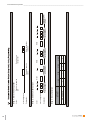
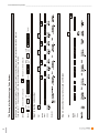
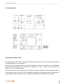
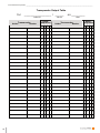
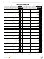
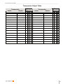
User Manual
ES 42 Electronic Key Switch
Order No. ____________________ | Device ____________
SCHAEFER GmbH | Winterlinger Straße 4 | 72488 Sigmaringen | Germany
Phone +49 7571 722-0 | Fax +49 7571 722-97 | [email protected] | www.ws-schaefer.de
ES 42 Electronic Key Switch _________________________________________________________________________________________
SCHAEFER GmbH
Winterlinger Str. 4
72488 Sigmaringen
Germany
Phone +49 (0) 7571 722-0
Fax +49 (0) 7571 722-99
www.ws-schaefer.de
[email protected]
Support
If you have any questions regarding this product, do not hesitate to contact us.
Copyright
Duplication (copy, print, microfilm or any other form) as well as electronic spreading of this document is only
permitted after formal written consent of SCHAEFER GmbH. SCHAEFER GmbH reserves the right for alterations of
technical details without prior notice.
For all transactions our General Conditions of Sale and Delivery are applied.
All rights reserved.
Ress.: 009267
Revision: 04/2005
2
ES 42 Electronic Key Switch _________________________________________________________________________________________
Contents
1.
General Description ………………………………………………………………………. 3
2.
Start-up ……………………………………………...………………………………………… 4
2.1
Installation Notice ……………………………………………………………………. 4
2.2
Multiple Use …………………………………………………………………………….. 5
3.
Audible Signals ………………………………………………………………………………. 5
4.
Operating Modes ..…………………………………………………………………………… 5
4.1
Pulse Time Programming/Switching Function …………………………………….. 5
4.2
Single-Relay Operation/Two-Relay Operation,
Both Relays Separately/Simultaneously ……………………………………………. 6
5.
Operation ………………………………………………………………………………………
5.1
Single-Relay Configuration used as a Pulse Generator ......................................
5.2
Single-Relay Configuration used as a Switch .....................................................
5.3
Two-Relay configuration used as a Pulse Generator ..........................................
5.3.1 Mode using “Both Relays Separately” ......................................................
5.3.2 Mode using “Both Relays Simultaneously” ...............................................
5.4
Two-Relay Configuration used as a Switch .........................................................
6.
Storing and Registering Transponder Identifiers ..................................................... 8
6.1
Storage ................................................................................................................ 8
6.2
Code Number Allocation (Beep Code) ................................................................ 9
Turbo Storage Special Mode without Code Number Output ................................... 9
6.3
Capacity of the ES 42 .......................................................................................... 9
6.4
Example for Code Number Output (Beep Code) during Programming ............... 10
6.5
Storage Attempt using Transponder Identifiers Stored Previously/
Query for Code Numbers of Stored Transponder Identifiers ............................. 11
6.6
Timeout ............................................................................................................. 11
Excursus on the Internal Assignment of Code Numbers ...................................... 11
7.
Deleting Single Transponders ..................................................................................
7.1
Deleting an Existing Transponder .....................................................................
7.2
Deleting Unavailable Transponders using a Code Number ..............................
7.2.1 Initiating a Code Number Delete Procedure ...........................................
7.2.2 Input of a Code Number to be Deleted ...................................................
7.2.3 Check Output and Delete Confirmation ..................................................
7.2.4 Example for Deletion using a Code Number .........................................
7.2.5 Errors during Code Number Input ...........................................................
8.
Deleting the Entire Memory ...................................................................................... 15
9.
Programming Special Function Cards ..................................................................... 15
10.
Appendix ..................................................................................................................... 16
- Technical Data
- Pin Configuration
- Transponder Output Table
6
6
7
7
7
7
8
12
12
12
12
12
13
14
15
3
ES 42 Electronic Key Switch _________________________________________________________________________________________
1.
General Description
The ES 42 electronic key switch is an electronic device designed to be used for identifying electronic keys
(transponders). This device can replace conventional key-operated switches. Transponders are used to carry out
non-contact locking functions instead of conventional keys.
Transponders are available in an ISO card format (cheque card format) identified by a KeyCard product designation
as shown in the below figure, or as key tags as shown in the below right figures.
BlueTag
KeyTag
All variants have identical functions.
The ES 42 will detect transponders already from a distance of a few inches or centimetres.
Every transponder is a unique specimen and has a unique and unalterable identifier which can only be read by an
electronic device. The ES 42 can store up to 156 transponder identifiers on a lasting basis and without battery
backup.
The current ES 42 version is equipped with two relays each (1 changeover contact each). The relays can be
programmed easily for use as either pulse generators or switches. When operated as a pulse generator, the pulse
duration (momentary contact function) can be set to either 0.3s, 3s, or to an “indefinite” duration. Every time a stored
transponder identifier is read out, the relays will be switched according to the defined configuration. Electrical signals
can be switched as desired through the relays’ potential-free contacts.
A coding switch (DIP switch, also see the pin description included in the appendix) can be used to switch over
between single-relay and two-relay operation. In two-relay operation, both relays can be switched either separately
or together.
Every read operation is acknowledged by an audible signal. Different signals are used as described in detail further
below to indicate to the user whether the transponder is recognized as authorized or not, and what action is being
carried out if any.
A light ring is available as an option for optical acknowledgement.
2.
Start-up
In general, the ES 42 is pre-programmed before delivery, i.e., the identifiers of the transponders included in the
delivery are stored in the ES 42 memory.
Special function cards (programming card, delete card, and reset card) are available on an optional basis to
reconfigure the ES 42. The ES 42 is ready for operation as soon as the operating voltage is connected. The system
can be operated using those transponders which have identifiers that are stored previously.
2.1
Installation Notice
Make sure that the front plate thickness does not exceed 0.08 in (2 mm) before using an ES 42 behind a stainless
steel front panel which does not have any opening in the area of the read-out unit.
4
ES 42 Electronic Key Switch _________________________________________________________________________________________
2.2
Multiple Use
It is basically possible to use several Electronic Key Switches in one fixture. However, the following requirements
must be met: - ES 42 Design MT 42 – minimum distance 84 mm (horizontally and vertically)
Each of the mounted Electronic Key Switches comes with a special shield. This shield is fixed to the faceplate using
2 welding bolts M 3 x 8.
3.
Audible Signals
Operation and configuration is supported by the audible signals listed as follows:
Short high-pitch beep.................................................................
Short high-pitch beep sequence (double)…..............................
Short high-pitch beep sequence (triple).....................................
Short low-pitch short high-pitch beep sequence .........…...........
Short high-pitch short low-pitch beep sequence...........…..........
Double short high-pitch short low-pitch beep sequence............
Triple short high-pitch short low-pitch beep sequence...…........
Quadruple short high-pitch short low-pitch beep sequence.......
Trill.................................................................................…........
Double-trill ..........................................................................…...
Triple-trill ...............................................................................….
Long trill ...............................................................................…..
Long low-pitch beep ............................................................…..
Long high-pitch beep ............................................................….
Double long low-pitch beep sequence ..................................….
Double long high-pitch beep sequence ................................….
Long high-pitch long low-pitch beep sequence.......................…
4.
Operating Modes
Pulse generator (momentary contact function): The selected relays close for the defined pulse time ( 0.3 s / 3 s /
“indefinite” ) after detecting a stored transponder identifier.
When set to “indefinite pulse time”, the selected relays will be closed for as long as a stored transponder is presented
to them.
Switch (switching function): The selected relays will switch to their corresponding other status whenever a stored
transponder is detected.
4.1
Pulse Time Programming / Switching Function
The system enters the programming mode when a programming card is held into the reading area of the ES 42.
This is acknowledged by a long high-pitch beep
. The programming card must be kept within the reading
area until a double trill
sounds first after 1.5 s. When the card is kept the reading area, the
following audible signals are given at an interval of approximately 1.5 s. These audible signals are used to set pulse
time and switching function:
Single short high-pitch - short low-pitch
Double short high-pitch - short low-pitch
Triple short high-pitch - short low-pitch
Quadruple short high-pitch - short low-pitch
.............…... Pulse time 0.3 s (momentary contact function)
…..……. Pulse time 3 s (momentary contact function)
.…. “Indefinite” pulse time (momentary contact function)
. Switching function
5
ES 42 Electronic Key Switch _________________________________________________________________________________________
The pulse time is set to the value assigned to the last audible signal sequence output when the programming card is
removed from the reading area.
4.2
Single-Relay Operation / Two-Relay Operation,
Both Relays Separately / Simultaneously
The position of DIP switch 4 determines the number of relays used: DIP 4 = OFF Æ single-relay operation, DIP
switch 4 = ON Æ two-relay operation.
In two-relay operation, DIP switch 3 determines whether both relays can be operated simultaneously or not.
Mode using “both relays separately”: It is not possible to operate both relays simultaneously. This means that
either relay 1 or relay 2 is switched when the ES 42 is used as a pulse generator (momentary contact function). In
switching function, either relay 1 or relay 2 can be switched over. Both relays can be switched on but only one after
the other.
Mode using “both relays simultaneously“: It is possible to operate either relay 1 or relay 2, or both relays
simultaneously. Accordingly, both relays can be switched on simultaneously for the momentary contact function, or
be switched over simultaneously for the switching function.
DIP switch
Function
4 = OFF
1 relay
4 = ON
2 relays
3 = OFF
both relays separately
3 = ON
both relays simultaneously
Note: The position of DIP switch 3 is not relevant in single-relay operation (DIP switch 4 = OFF).
5.
Operation
The steps described below can only be carried out using transponders which are known to the system (i.e., stored in
the system; cf., Section 6, Storing and Registering Transponder Identifiers).
Unidentified transponders are rejected with a long high-pitch long low-pitch beep sequence:
Note: A transponder is never programmed itself! Only the ES 42 memory content is modified. This enables the ES
42 to detect whether an unalterable electronic key (transponder) "fits" or not. Correspondingly, the same
transponders can be used as “valid keys” for more than one ES 42.
5.1
Single-Relay Configuration used as a Pulse Generator (DIP switch 4 = OFF)
A transponder is held into the reading area of the ES 42, and recognized after 0.1 s, approximately. The pulsing
function is carried out. This is acknowledge by a short low-pitch short high-pitch beep sequence
for the fixed
times (0.3 s and 3 s). The pulse end is acknowledged by a short high short low-pitch beep sequence:
The read-out unit is disabled for approximately 1s after the end of every fixed duration pulse.
A subliminal “tacking” sound is produced, and the relay picks up when a transponder is detected if an “indefinite”
pulse duration was programmed (see Section 4.1). The “tacking” sound stops, the pulse stops, and the relay drops
out as soon as the transponder is removed from the reading area.
6
ES 42 Electronic Key Switch _________________________________________________________________________________________
5.2
Single-Relay Configuration used as a Switch (DIP switch 4 = OFF)
A transponder is held into the reading area of the ES 42, and detected after approx. 0.1 s.
-
A relay switched OFF before will switch ON now.
A relay switched ON before will switch OFF now.
Both is acknowledged by a trill:
Note: The initial circuit status will be restored after any power failure.
5.3
Two-Relay Configuration used as a Pulse Generator (DIP switch 4 = ON)
5.3.1
Mode using “Both Relays Separately” (DIP switch 3 = OFF)
A transponder is held into the reading area of the ES 42, and detected after approx. 0.1 s. This is indicated by a
short high-pitch beep:
Relay 1 switches when the transponder is removed from the reading area after the beep.
Relay 2 switches when the transponder is kept within the reading area after the beep.
The corresponding relay switches for the programmed fixed pulse time (see Section 5), and the pulse start is
indicated by a short low-pitch short high-pitch beep sequence
. A short high-pitch short low-pitch beep
sequence
sounds when the ON period is over.
When an “indefinite” pulse duration is programmed, a short low-pitch short high-pitch beep sequence
is also
emitted but no relay picks up yet after selecting relay 1 (taking the transponder out after a short high-pitch beep
). Relay 1 will only switch on when the transponder is moved into the reading area again during the next 2.5 s.
This is acknowledged by a subliminal “tacking” sound. This ON period can be interrupted when the transponder is
taken out of the reading area for a very short time (max. 0.7 s). A longer interruption will finally cancel the closing
operation as indicated by a short high-pitch short low-pitch beep sequence
. The relay will be activated again
when it is selected.
To switch relay 2 for an “indefinite” pulse duration, the card is kept in the reading area continuously. A subliminal
“tacking” sound is heard immediately after the short low-pitch short high-pitch audible signal
, and relay 2 is
switched on. This ON period can be interrupted when the transponder is taken out of the reading area for a very
short time (max. 0.7 s). A longer interruption will finally cancel the closing operation as indicated by a short highpitch short low-pitch beep sequence
. The relay will be activated again when it is selected.
5.3.2
Mode using “Both Relays Simultaneously” (DIP switch 3 = ON)
A transponder is held into the reading area of the ES 42.
A first audible signal
removed at this time.
sounds after approx. 0.1 s. The first relay will be activated when the transponder is
A second audible signal
sounds after 1 s when the transponder is kept within the field. The second relay will
be activated when the transponder is removed at that time.
A third audible signal
sounds after 1 s when the transponder is kept within the field. Both relays will be
activated simultaneously now. The transponder does not need to be removed from the field for this.
The selected relays will be switched each for the programmed fixed pulse time (see Section 4.1), and the pulse start
will be indicated by a short low-pitch short high-pitch beep sequence
. A short high-pitch short low-pitch beep
sequence
will sound when the ON period is over. (…continued next page!)
7
ES 42 Electronic Key Switch _________________________________________________________________________________________
When an “indefinite” pulse duration is programmed, a short low-pitch short high-pitch beep sequence
is also
emitted but no relay picks up yet after relay selection (removing the transponder from the reading area for relay 1 or
2). The ON period will only start when the transponder is moved into the reading area again during the next 2.5 s.
This is acknowledged by a subliminal “tacking” sound. The transponder can be kept continuously within in the field to
hold both relays for an indefinite period. This ON period can be interrupted when the transponder is taken out of the
reading area for a very short time (max. 0.7 s). A longer interruption will finally cancel the closing operation as
indicated by a short high-pitch short low-pitch beep sequence
. The relay will be activated again when it is
selected.
5.4
Two-Relay Configuration used as a Switch (DIP switch 4 = ON)
This operating mode basically corresponds to the use as a pulse generator with fixed pulse times as described in
Sections 5.3.1 and 5.3.2. The settings for “both relays separately” / “both relays simultaneously” (DIP switch 3) are
also valid in this configuration. The difference is that every switching operation is acknowledged by a trill
and always establishes a defined status which is only modified by another switching operation, and not at
the expiration of a previously defined period of time.
Note: It is possible to switch both relays simultaneously as described (DIP switch 3 = ON), and even when one relay
is ON while the other is OFF. In this case, both relays will change status simultaneously and will be in an inverse
status after the switching operation.
The circuit status is resumed after any power failure.
6.
Storing and Registering Transponder Identifiers
An additional code number is assigned automatically to every transponder when its identifier is stored in an ES 42.
The ES 42 will output this code number as a beep immediately after programming.
The purpose of this code number is to allow the deletion of transponders which are stored but not available at the
time of deletion (see Section 7.2, Deleting unavailable transponders ...).
It is useful to write down a transponder’s laser-engraved serial number laser (unique number) before storing. The
code number indicated by the beep sound can be allocated unequivocally to the corresponding transponder, and be
recorded, e.g., in the table enclosed in the appendix. The future owner/holder of the transponder should also be
included in this table if possible.
6.1
Storage
The system enters the programming mode when the programming card is held into the reading area of the ES 42.
This is acknowledged by a long high-pitch beep:
A transponder can be moved into the reading area of the ES 42 during the next 4 seconds. The data of this
transponder will be saved to the ES 42 memory now if this transponder’s identifier has not been stored in this ES 42
so far, and if the memory is not fully occupied (maximum number of transponder identifiers: 156). This is
acknowledged by a trill:
Previously stored identifiers will be rejected, and a long high-pitch long low-pitch two-tone sequence will sound:
In both cases, the code number, which is assigned to that transponder automatically by the system, will be output by
a beep after another period of 3 to 6 seconds (see Section 6.2).
The procedure will be cancelled when the first 4 seconds have passed without being used for any action (see
Section 6.6). After storing a transponder, the system returns to the normal status. The programming card must be
read in first to start again and store another transponder.
8
ES 42 Electronic Key Switch _________________________________________________________________________________________
6.2
Code Number Allocation (Beep Code)
The entire code number consists of 4 part code numbers. Every part code number is signalized by a beep
sequence. Every beep sequence consists of 1 to 4 beeps. You should keep note of the total code number resulting
from all 4 beep sequences when this number is output by the ES 42.
Beep sequences are output as single short high-pitch beeps. A distinctive pause is made between every short highpitch beep such that is possible to distinguish clearly, e.g., between 3 and 4 subsequent high-pitch beeps.
Example:
means 2.
To differentiate between two beep sequences, a long low-pitch beep sounds:
The programming mode is terminated after the output of the fourth beep sequence. This is indicated by two long
low-pitch beeps:
The whole storing procedure is shown again in a diagram in Section 6.4.
Turbo Storage Special Mode without Code Number Output:
A specific procedure, which allows transponders to be stored very quickly one after the other, is available to advanced users who
fully understand and are well versed in the ES 42 system. First of all, any user of this method should fully understand and be able
to proceed according to the “Excursus on the Internal Assignment of Code Numbers” included after Section 6.6.
The programming card is read in to set the system to the programming mode acknowledged by a long high-pitch beep
.
Leave the programming card in the reading area of the ES 42 for approx. 1.5 s more until a double trill is heard
.
The ES 42 enters the turbo storage mode when the programming card is removed from the reading area within 1 s from now. A
subliminal “tacking” sound is used to indicate that mode. (The “Set Pulse Time / Switching Function” mode is activated if the
programming card is kept in the reading area for a longer period, see Section 4.1.)
In the turbo storage mode, transponder identifiers not stored so far can be stored one after the other. Every stored identifier is
acknowledged by a trill
, and the “tacking” sound is interrupted at the same time. The next identifier can be stored as
soon as the “tacking” sound is heard again without reading in the programming card before.
The “tacking” sound will last for approximately 4s every time. If no new transponder identifier is stored during this time, the turbo
storage mode will be terminated, and a long high-pitch long low-pitch beep sequence
will sound. The turbo
storage mode will also be terminated when the memory is full, or when an attempt is made to store the identifier of a special
function card or of a transponder stored before. In the latter case, the code number of the transponder identifier stored before will
be output as a beep code after terminating the storage mode.
All stored identifiers acknowledged before termination will be preserved.
Although there is no code number output, code numbers are assigned after a successful storage in this mode as well. Any code
numbers possibly set free before are assigned first in this process, starting with the lowest number.
It is absolutely necessary to prepare and document the storage procedure with great care in order to keep track of the code
numbers assigned to every transponder.
6.3
Capacity of the ES 42
The entire storage procedure can be repeated as often as necessary until the memory area for 156 identifiers is fully
occupied. A transponder with a stored identifier is recognized as authorized immediately after completing the
storage procedure.
Any attempt to store an identifier of another transponder will be rejected when the memory is full. The device will
terminate the programming mode, and sound a high-pitch and low-pitch double tone:
as a termination signal.
9
10
1
MR. SAMPLE
Transponder
identifier
Step 3: Documentation
Explanation:
Acknowledgement:
Count:
2
3
3
1st BS
Break
Read in programming
card
Step 2: Code number output
Explanation:
Acknowledgement:
Action:
Step 1: Store the transponder
1
2nd BS
1
2
3rd BS
Programming mode
starts
4
4th BS
Break
Read in a new
transponder
1
2
Break
New transponder
is stored
1
2
3
4
ES 42 Electronic Key Switch _________________________________________________________________________________________
ES 42 Electronic Key Switch _________________________________________________________________________________________
6.5
Storage Attempt using Transponder Identifiers Stored Previously/
Query for Code Numbers of Stored Transponder Identifiers
If it is already stored, a transponder identifier will not be stored again. A long high-pitch long low-pitch beep
sequence
will sound as a termination signal instead of the acknowledgement trill
which
sounds for every identifier that is stored successfully after reading in the programming card.
Three seconds after the termination signal, a beep code will indicate the code number assigned to this transponder
as described before when it was stored. This makes it possible to listen to and check stored transponder identifiers
even later on.
6.6
Timeout
The ES 42 will abort the programming mode, and return to normal operation when no other transponder is detected
within 4 s after reading in the programming card.
A long high-pitch long low-pitch beep sequence will sound as a termination signal:
Note: To ensure proper functioning, please note that only one transponder may be within the reading area of the ES
42 at any given time.
Excursus on the Internal Assignment of Code Numbers
The beep code is a modified form of the base-4 number system (cf., binary, octal, decimal, or hexadecimal system). Every number
is incremented by 1 in this case as a “zero” is hardly useful as a beep code. Furthermore, the system starts with identifier number
“zero” which corresponds to the “first” identifier in common parlance. So, the 50th identifier corresponds to a computational
internal code of 49.
Accordingly, the ES 42 assigns up to 156 code numbers starting with 0 in an ascending order. The first number is 0 0 0 0 as every
code number is expressed by 4 digits. Beep sequence 1 – 1 – 1 – 1 is obtained by incrementing every number by 1.
The following table can be used, e.g., to obtain the beep sequence which corresponds to the 100th or 7th stored card (strictly
following the ascending order and without any deletions in the meantime!):
100
99
24
6
1
:
:
:
:
1
4
4
4
4
=
=
=
=
=
99
24
6
1
0
(Conversion to internal code)
Remainder
Remainder
Remainder
Remainder
Total:
Increment by 1:
Beep code:
3
0
2
1
1 2 0 3
1 1 1 1
2 3 1 4
7
6
1
0
0
:
:
:
:
1
4
4
4
4
=
=
=
=
=
6
1
0
0
0
(Conversion to internal code)
Remainder
Remainder
Remainder
Remainder
Total:
Increment by 1:
Beep code:
2
1
0
0
0 0 1 2
1 1 1 1
1 1 2 3
(This makes it easy to see why the code number for the very last memory location has 3 – 2 – 3 – 4 as a beep code.)
Whenever a transponder identifier is deleted, the corresponding code number is deallocated. Several code numbers are
deallocated when more than one transponder identifier is deleted. These released code numbers are assigned again whenever
new transponder identifiers are allocated again later on. The lowest code number is used first for these new allocations. This also
applies to free code numbers which have never been used before, and which clearly have a higher numerical value. Accordingly,
released code numbers are used first before assigning any numbers never used before. As a consequence, it is probable to have
code number allocations which differ from the numbers originally allocated whenever several transponder identifiers are deleted
and stored again later on. Code number allocations will only remain as before when the internal structure has not been modified
again by other delete and/or storage operations carried out in the meantime, provided that the deleted transponders are stored
exactly in the same order as at the first time.
To sum up, it is recommended to write down the audible beep code whenever a transponder identifier is stored to be sure that
this really is the valid code when you need it (to delete an unavailable transponder.)
11
ES 42 Electronic Key Switch _________________________________________________________________________________________
7.
Deleting Single Transponder Identifiers
7.1
Deleting Available Transponders
The system enters the delete mode when the delete card is held in the reading area of the ES 42. This is
acknowledged by a long high-pitch beep:
Any stored transponder identifier will be deleted from the memory when it is detected by the ES 42 in its reading
area within the next 4 seconds.
This is acknowledged by a long trill:
Then, the system will need a few seconds to carry out its internal delete cycle.
A transponder identifier not stored in the ES 42 cannot be deleted. If an attempt is made to do so, the delete
procedure is cancelled, and a long high-pitch long low-pitch beep sequence sounds
.
After deletion, the system returns to its normal status. To delete another transponder identifier, the delete card
needs to be read in again first.
The system returns to its normal status when no other transponder is detected within 4 seconds after detecting the
delete card.
A termination signal is given by a long high-pitch long low-pitch beep sequence:
It is not possible to delete a special function card (programming card, reset card, or delete card) using this
procedure.
The delete process can be repeated as often as necessary until all identifiers of stored transponders are deleted.
Transponders which have their identifiers deleted are not recognized as valid any longer.
Note: To ensure proper functioning, please note that only one transponder may be within the Reading area of the ES
42 at any given time.
7.2
Deleting Unavailable Transponders Using a Code Number
The ES 42 allows the deletion of identifiers belonging to transponders which are not available any longer. This may
be required, e.g., when the holder of a transponder has lost his or her transponder, or fails to return the transponder
although there is a return obligation.
To delete such identifiers, you need the four-digit code number written down (hopefully) when the transponder
identifier was stored.
7.2.1 Initiating a Delete Procedure
The complete delete procedure is carried out using the delete card. A long high-pitch beep
to acknowledge the detection of the delete card.
will sound
7.2.2 Input of a Code Number to be Deleted
The delete card is kept within the reading area of the ES 42. A triple trill
will sound after
approx. 2 s, and the first short high-pitch beep will sound for the first part code number approx. 1.5 s after that:
12
ES 42 Electronic Key Switch _________________________________________________________________________________________
-
If the first part code number is 1, remove the delete card from the reading area until a long low-pitch beep is
heard:
-
If the first part code number is 2, keep the delete card in the reading area after the first short high-pitch
beep, and until the second short high-pitch beep is heard:
After that beep, remove the delete card from the reading area until a long low-pitch beep sounds:
-
Proceed accordingly when the part code number is 3 or 4. A long low-pitch beep always indicates the end of
a part code number input.
To enter the second part code number, the delete card must be moved back into the reading area of the ES 42 right
away. The input of the second, third, and fourth part code number is done as described above for the input of the
first part code number:
The number of short high-pitch beeps
corresponds to the respective part code number (while the delete card is
in the reading area), while long low-pitch beeps
mark the pauses between the part code numbers (after
removing the delete card from the reading area.)
The input mode is terminated after the input of the fourth part code number. This is acknowledged by two long lowpitch beeps:
7.2.3 Check Output and Delete Confirmation
The delete card should be kept out of the reading area of the ES 42 now to avoid any accidental deletion at the end
of the procedure.
The ES 42 will output the code number just entered when the desired code number is available in the memory. This
output corresponds to the code number output during transponder programming (see Sections 6.2 and 6.4 / Step 2).
The output mode is terminated after the output of the fourth part code number. Again, this is indicated by sounding
two long low-pitch beeps:
After this, the ES 42 is in the input mode again.
For final deletion, a confirmation needs to be made by reading in the delete card once again within the next 3
seconds when the beep code check output corresponds to the code number that is assigned to the transponder for
which the identifier is to be deleted.
-
The identifier of the transponder which corresponds to the code number entered will be deleted from the
memory when the delete card is detected in time. This transponder is not valid any longer. This will be
acknowledged by a long trill:
After this, the ES 42 returns to the normal status.
-
The system will return to the normal status without making any modification when no confirmation is made
by the delete card. This is a cancellation, and it will be indicated by a long high-pitch long low-pitch beep
sequence
. The system will be back in the normal status after this.
The following page includes a diagram showing the whole procedure to be used to delete an unavailable
transponder.
13
14
Long
low
pitch
Delete card in ES 42 reading area
Short
high
pitch
Delete
card
Delete
card
Delete
card
Action:
Audible
signal:
Input:
Delete
card
Delete
card
Double
long low
pitch
Delete card out of ES 42 reading area
Long trill
Delete
card
Step 2: Code number output (check) and confirmation
Explanation:
Action:
Audible
signal:
Input:
Step 1: Enter the code number
Beeps:
Symbols:
Delete
card
Long
high
pitch
Delete
card
Triple trill
Delete
card
Delete
card
Mr. Sample has lost his transponder. To prevent access by unauthorized persons, this transponder should be deleted.
Code number 3 1 2 4 was assigned to Mr. Sample’s transponder when it was stored.
7.2.4 Example for Deletion using a Code Number
Delete
card
Delete
card
ES 42 Electronic Key Switch _________________________________________________________________________________________
ES 42 Electronic Key Switch _________________________________________________________________________________________
7.2.5 Errors during Code Number Input
When a part code number of a code number has been entered incorrectly by mistake, the procedure can be
cancelled easily by not holding the delete card into the reading area of the ES 42.
The error will be detected because a “1” must be recognized every time a different number is read in such that the
ES 42 will return to its normal status. This will be indicated by a long high-pitch long low-pitch beep sequence
.
You should wait for the subsequent code output when an error occurs as the fourth part code number of the code
number is entered. The ES 42 will also return to the normal status without making any changes whenever deletion is
not confirmed by presenting the delete card once again after the output. The termination signal given in this case is
also a long high-pitch long low-pitch beep sequence:
The same termination sequence is followed when the code number entered is not possible (i.e., outside the
specified range), or when it is not assigned to any transponder identifier at that time.
After cancellation, the delete procedure can be restarted as before.
8.
Deleting the Entire Memory
The system enters the reset mode when the reset card is held into the reading area of the ES 42.
This is indicated by two long high-pitch beeps:
You should take the reset card out of the reading area at this time, and wait for acknowledgment by a single long
high-pitch beep:
Move the reset card back into the reading area again after that beep. The entire memory will be deleted now.
Successful deletion is acknowledged by a long trill
: The system returns to its initial
state. No transponder identifier is recognized as valid any longer. But special function cards (programming card,
delete card, reset card) are not deleted and remain valid.
9.
Programming Special Function Cards
Special function cards (programming card, delete card, reset card) are pre-programmed when delivered. But users
can overwrite these cards using DIP switches and the identifiers of other transponders which have the same
markings.
DIP switches 1 and/or 2 can be set and used to assign the “Programming”, “Delete”, or “Reset” functions to every
transponder marked by a corresponding label.
This is always acknowledged by two long high-pitch beeps
corresponding transponder is read in and recognized.
which
sound
when
the
From this time on, only this transponder will have the special function assigned, while a “former” transponder cannot
be used for that function any longer!
When you attempt to assign a special function to a transponder which is already used for another function, the
transponder will not be accepted, and a long high-pitch long low-pitch beep will sound
as a cancellation signal.
If the same transponder was already defined for the special function to be assigned, this transponder’s identifier will
remain in the memory, and the same acknowledgement as for a new allocation will be given:
15
ES 42 Electronic Key Switch _________________________________________________________________________________________
The table below shows the DIP switch positions assigned to the storage of special function cards:
DIP switch
Special function card
1 ON 2 OFF
ProgrammingCard
1 OFF
2 ON
1 ON 2 ON
DeleteCard
ResetCard
DIP switches 1 and 2 must be set back to OFF to resume normal operation.
Note: All DIP switches may also be set to ON or OFF when energized if the tool used cannot cause any short circuit.
10.
Appendix
Specifications
- Power supply
22V - 27V DC
Closed-circuit current
- Relay contact assembly
max. 50 mA
Operating current
max. 70 mA
with 2 relays picked up
Switched voltage
max. 50 V DC / 75 V AC
Switched current
max. 1 A
Switching capacity max. 30 W
- Operating temperature
0 °C – 55 °C
- Number of participants
max. 156
- Frequency
125 kHz
- Number of codes possible
1.1 x 10¹²
- Recognition time
approx. 0.1 s
- Reading distance
max. 50 mm
- Casing dimensions
52 mm x 41.5 mm x 20 mm
- BZT1 approval number
G750741J
1
16
German Federal Office for Telecommunication Approvals
ES 42 Electronic Key Switch _________________________________________________________________________________________
Pin Configuration
Relay 1
Recall Light
(Illuminated Rim)
Relay 2
relay 1
relay 1
relay 1
GND
24V DC
L1
L2
relay 2
relay 2
relay 2
DIP switch 1
DIP switch 2
DIP switch 3
DIP switch 4
Transponder Output Table
The following tables can be used to write down and assign serial number, holder, and the beep sequence output
during programming for every transponder.
The name of every transponder holder, and the laser-engraved numbers on the rear side of every transponder
should be written down clearly in the columns under “Transponder Holder Number”. The next columns are
named 1 to 4 (1st to 4th Beep Sequence).
We should like to point out once again that it is absolutely necessary to write down the laser-engraved number of
every transponder next to the name of the corresponding transponder holder (especially when a large number of
transponders is issued). Otherwise, it may be very difficult to administer the transponders on a logical basis.
17
ES 42 Electronic Key Switch _________________________________________________________________________________________
Transponder Output Table
for:
__________________ / ______
Order No.
TransponderHolder
18
Number
on _________
Device
BeepSequence
1 2 3 4
Date
TransponderHolder
Number
BeepSequence
1 2 3 4
1 1 1 1
1 2 3 3
1 1 1 2
1 2 3 4
1 1 1 3
1 2 4 1
1 1 1 4
1 2 4 2
1 1 2 1
1 2 4 3
1 1 2 2
1 2 4 4
1 1 2 3
1 3 1 1
1 1 2 4
1 3 1 2
1 1 3 1
1 3 1 3
1 1 3 2
1 3 1 4
1 1 3 3
1 3 2 1
1 1 3 4
1 3 2 2
1 1 4 1
1 3 2 3
1 1 4 2
1 3 2 4
1 1 4 3
1 3 3 1
1 1 4 4
1 3 3 2
1 2 1 1
1 3 3 3
1 2 1 2
1 3 3 4
1 2 1 3
1 3 4 1
1 2 1 4
1 3 4 2
1 2 2 1
1 3 4 3
1 2 2 2
1 3 4 4
1 2 2 3
1 4 1 1
1 2 2 4
1 4 1 2
1 2 3 1
1 4 1 3
1 2 3 2
1 4 1 4
ES 42 Electronic Key Switch _________________________________________________________________________________________
Transponder Output Table
TransponderHolder
Number
BeepSequence
1 2 3 4
TransponderHolder
Number
BeepSequence
1 2 3 4
1 4 2 1
2 2 1 1
1 4 2 2
2 2 1 2
1 4 2 3
2 2 1 3
1 4 2 4
2 2 1 4
1 4 3 1
2 2 2 1
1 4 3 2
2 2 2 2
1 4 3 3
2 2 2 3
1 4 3 4
2 2 2 4
1 4 4 1
2 2 3 1
1 4 4 2
2 2 3 2
1 4 4 3
2 2 3 3
1 4 4 4
2 2 3 4
2 1 1 1
2 2 4 1
2 1 1 2
2 2 4 2
2 1 1 3
2 2 4 3
2 1 1 4
2 2 4 4
2 1 2 1
2 3 1 1
2 1 2 2
2 3 1 2
2 1 2 3
2 3 1 3
2 1 2 4
2 3 1 4
2 1 3 1
2 3 2 1
2 1 3 2
2 3 2 2
2 1 3 3
2 3 2 3
2 1 3 4
2 3 2 4
2 1 4 1
2 3 3 1
2 1 4 2
2 3 3 2
2 1 4 3
2 3 3 3
2 1 4 4
2 3 3 4
19
ES 42 Electronic Key Switch _________________________________________________________________________________________
Transponder Output Table
TransponderHolder
Number
BeepSequence
1 2 3 4
Holder
Number
BeepSequence
1 2 3 4
2 3 4 1
3 1 3 1
2 3 4 2
3 1 3 2
2 3 4 3
3 1 3 3
2 3 4 4
3 1 3 4
2 4 1 1
3 1 4 1
2 4 1 2
3 1 4 2
2 4 1 3
3 1 4 3
2 4 1 4
3 1 4 4
2 4 2 1
3 2 1 1
2 4 2 2
3 2 1 2
2 4 2 3
3 2 1 3
2 4 2 4
3 2 1 4
2 4 3 1
3 2 2 1
2 4 3 2
3 2 2 2
2 4 3 3
3 2 2 3
2 4 3 4
3 2 2 4
2 4 4 1
3 2 3 1
2 4 4 2
3 2 3 2
2 4 4 3
3 2 3 3
2 4 4 4
3 2 3 4
3 1 1 1
3 1 1 2
3 1 1 3
3 1 1 4
3 1 2 1
3 1 2 2
3 1 2 3
3 1 2 4
20
Transponder-
ES 42 Electronic Key Switch _________________________________________________________________________________________
Transponder Output Table
TransponderHolder
Number
BeepSequence
1 2 3 4
TransponderHolder
Number
BeepSequence
1 2 3 4
21
ES 42 Electronic Key Switch _________________________________________________________________________________________
Notices:
22
ES 42 Electronic Key Switch _________________________________________________________________________________________
Notices:
23
ES 42 Electronic Key Switch _________________________________________________________________________________________
Notices:
24