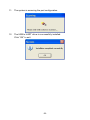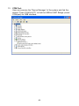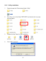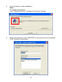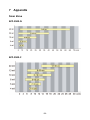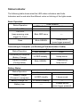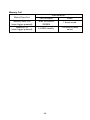
1
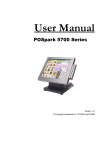
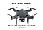
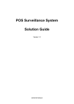
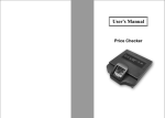
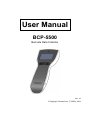
User Manual BCP-5500 Barcode Data Collector Ver. 1.0 © Copyright Fametech Inc. (TYSSO), 2012 Contents 1 Before Use Safety Precaution .................................................................................... 3 2 Introduction 2.1 Features .......................................................................................... 4 2.2 Specifications .................................................................................. 5 2.3 Package .......................................................................................... 6 2.4 Product Description ......................................................................... 7 3 Getting Started 3.1 Charging the Battery ....................................................................... 9 3.1.1 Charge the battery via USB Interface of Computer ............. 9 3.1.2 Charge the battery via RS-232 Cable and USB Power Cable ................................................................. 9 3.1.3 Charge the battery via RS-232 Cable and Optional Power Adaptor ...................................................... 10 3.2 Battery Care .................................................................................. 11 3.2.1 Battery Replacement ....................................................... 12 3.2.2 Battery Disposal ............................................................... 12 4 Operating Your Data Collector 4.1 Switch On/Off ................................................................................ 13 4.2 Perform scan and collect data ...................................................... 13 4.3 Job Mode ...................................................................................... 14 4.3.1 Mode 0 (default) ................................................................. 15 4.3.2 Mode 1 (Advance Mode) .................................................... 16 -1- 5 Connecting to the Computer 5.1 5.2 Connecting to the Computer ......................................................... 22 5.1.1 USB Interface Installation .................................................. 22 5.1.2 RS-232 interface Installation .............................................. 22 Driver & Utility Installation ............................................................. 23 5.2.1 Install the USB Virtual COM Port Driver (for USB interface only)....................................................... 24 5.2.2 Utility installation ................................................................ 31 6 Configuring Your Data Collector /Data Management 6.1 Access to the Utility....................................................................... 34 6.2 File ................................................................................................ 35 6.3 Setting ........................................................................................... 36 6.3.1 Barcode .............................................................................. 37 6.3.2 General Parameter............................................................. 38 6.3.3 Job Mode Selection............................................................ 39 6.4 Transmit ........................................................................................ 41 6.5 Upload the Data to the Computer ................................................. 43 6.5.1 Upload the Data ................................................................. 44 6.5.2 Erase Data in BCP ............................................................. 46 6.5.3 Change Password .............................................................. 47 6.5.4 Enable/Disable Real Time Clock (Timestamp) .................. 48 6.5.5 Upload Data with Machine ID ............................................ 51 7 Appendix Scan Zone ............................................................................................. 54 Status Indicator ...................................................................................... 55 -2- 1 Before Use Safety Precaution 1. 2. 3. 4. 5. 6. 7. 8. 9. 10. 11. 12. 13. 14. Read the manual carefully before use Always keep the manual in proper location for references. Always keep this instruction manual ready at hand for your reference Install in accordance with the instructions. Heed all warnings messages and notifications to avoid injury to self or people; misuse may cause malfunction or damage to the product Do not operate the product and accessories near water, moisture, or dusty location; it may cause electrical shock injury or fire. Do not place or operate the product near any heat sources such as radiators, heat registers, stoves, or other apparatus that produce heat. It may expose the product to the danger of Fire and Explosion. Clean only with dry cloth. Use ONLY supplied or accessories specified by manufacturer. Use of anything other than supplied or approved accessories will void the warranty, may cause malfunction and, and may put the User or other person at risk of injury. DO NOT aim the product at eyes of people or animals. Some product models use a strong light source as a scanning aid may cause serious eye injury. Protect the cords or cables from being walked on or pinched particularly at plugs, convenience receptacles, and the point where they exit from the apparatus. Unplug this apparatus during lightning storms or when unused for long periods of time. The Service is performed by qualified service personnel only. Servicing is required when the product and/or the accessories have been damaged in any way, such as power cable or plug is damaged, liquid has been spilled or objects have fallen into the product, the product has been exposed to rain or moisture, does not operate normally, or has been dropped. DO NOT dissemble or modify the product, accessories, and the components (e.g. the pre-installed rechargeable battery). It should cause damage to the product and injury to people and the warranty is terminated. -3- 2 Introduction The BCP-5500 is a compact and cost-effective data collector that allows its operator to collect data without distance limitation. It is the ideal device for inventory and stocktaking. By featuring the fast-responding CCD sensor and the powerful decoder, BCP-5500 is capable of performing data-collecting tasks that time is an important issue. And the stylish and easy-to-grip design is a merit for operators especially for long-time operation. Equipped with the application software, and large internal memory, BCP-5500 offers the advantages of high-speed scanning, reliability and easy operation. In addition, it also gives the operators greater mobility for scanning those tough to reach barcodes. The embedded utility software provides users with easy data management of the scanned data that suits for variety of business needs: Inventory, Warehouse, Stock and Order Picking, and Shipping/Receiving Management. 2.1 Features Stylish design and light-weight Pre-defined data formats Vivid and Clear Display Easy operation by navigation keys High speed CCD scan engine Interface: USB or RS-232 Rechargeable battery (battery charge via Recharge/Communication Cradle) Real Time Clock; uploaded data with timestamp Machine ID Easy configuration utility Communication SDK -4- 2.2 Specifications Model System CPU Memory OS Application Software Operating System Support Programming Language Data Management SDK Software Readable Bar Code BCP-5500-C BCP-5500-N 8-bit CPU 224KB Proprietary Windows-base (98/Me/2000/XP/Vista/Win 7) Windows-base Application Software Data Management Utility Software Upload communication SDK UPC-A, EAN-8/JAN-8, UPC-E, ISBN/ISSN, RSS-14, CODE 11, CODE 93, MSI-Plessey, CODABAR/NW7, CODE4, EAN-13/JAN-13, CODE 39, CODE 32, Interleaved 2 of 5/IATA, Matrix 2 of 5, China Postage, CODE 128 Display Display Keypad Buzzer LED Connectivity Interface Transmission Rate Scanner 128x64 dot-matrix graphic LCD with back-light 18 character x 4 line, 7x18 dot display pattern 3 keys (2 navigation keys, and enter key) Audio Buzzer LED Indicator Standard RS-232 or USB (virtual RS-232) 19200 bps 625nm ±10nm 650nm ±10nm, CCD Visible Laser diode Scan Speed 100 scans/sec. Minimum print contrast 0.45 Depth of Field* 3~21 cm 3~48 cm Maximum Pitch 65+ o Minimum Skew 50+ o Minimum Bar Width 4 mil * The depth of field may vary due to environment conditions and barcode resolution. Scanner Type -5- Others Operation Battery Operating Time Material Color Compliance Weight Dimension Operating Temperature Operating Humidity Storage Temperature Storage Humidity Rechargeable Lithium Battery Pack (1100mAh / 3.7V) battery charge via Recharge and Communication Cradle Over 30 hours (approx. 45,000 scans, battery fully charged) ABS Front: Black, Body: White FCC class A scanner: 136.1 g / cradle: 170.2 g 175 x 45 x28 mm 0°C~45°C 10% ~ 85% RH non-condensing -20°C~ 65°C 5% ~ 95% RH non-condensing The specifications may be changed/updated without prior notice. 2.3 Package Standard Package Data Collector Utility CD Recharge and Communication Cradle User Manual USB Power Cable (for RS-232 interface only) x1 x1 x1 x1 x1 Optional Accessory: External power adapter (for RS-232 interface only) -6- x1 2.4 Product Description Part Descriptions 1. Scan Window 2. LED Indicator 3. Display 4. Navigation Buttons (Arrow Up/Enter/Arrow Down) 5. Scan Trigger 6. Connector to Recharge and Communication Cradle 7. Wrist Strap Hole 8. LED Indicator (Charge and Communication Cradle) 9. Connector to Data Collector Unit (Recharge and Communication Cradle) Data Collector Unit -7- Recharge and Communication Cradle -8- 3 Getting Started 3.1 Charging the Battery It’s recommended to have the battery fully charged before use. User can charge the battery via the supplied USB Cable or via the RS-232 cable with optional external power adapter. 3.1.1 Charge the battery via USB Interface of Computer To Host PC Charge the battery via USB Interface on the computer 1. Turn on the computer. 2. Connect the USB connector to the USB port on the computer. 3. Install the data collector to the recharge and communication cradle. The data collector is activated and the battery is recharging automatically (There is a beep sound and the LED indicator lit RED steadily). 4. As the battery is fully charged, the LED indicator lit GREEN to indicate the battery charge is completed. 5. Remove the data collector from the cradle. The data collector is ready to use. 3.1.2 Charge the battery via RS-232 Cable and USB Power -9- Cable USB Power Cable Host PC Charge the battery via RS-232 Interface and USB Power Cable 1. Turn off the computer. 2. Connect the D-type 9-pin RS-232 connector to the PC. 3. Connect the USB Power Cable to the rear DC Jack of the RS-232 connector and HOST PC. 4. Install the data collector to the recharge and communication cradle. The data collector is activated and the battery is recharging automatically (There is a beep sound and the LED indicator lit RED steadily). 5. As the battery is fully charged, the LED indicator lit GREEN to indicate the battery charge is completed. 6. Remove the data collector from the cradle. The data collector is ready to use. Warning: Use only the supplied cable to charge the battery. DO NOT dissemble or modify the data collector and the pre-installed rechargeable battery. It should cause damage to the product and the injury to the people near the product. 3.1.3 Charge the battery via RS-232 Cable and Optional Power -10- Adaptor To Host PC Power Adaptor Cradle Charge the battery via RS-232 Interface and Optional Power Adaptor 1. Turn off the computer. 2. Connect the D-type 9-pin RS-232 connector to the PC. 3. Connect the barrel connector of the power adaptor to the rear DC Jack of the RS-232 connector. 4. Plug the power adaptor to the power outlet. 5. Install the data collector to the recharge/communication cradle. The data collector is activated and the battery is recharging automatically (There is a beep sound and the LED indicator lit RED steadily). 6. As the battery is fully charged, the LED indicator lit GREEN to indicate the battery charge is completed. 7. Remove the data collector from the cradle. The data collector is ready to use. Warning: Use only the supplied cable and optional power adapter (purchased separately) to charge the battery. DO NOT dissemble or modify the data collector and the pre-installed rechargeable battery. It should cause damage to the product and the injury to the people near the product. 3.2 Battery Care -11- The pre-installed battery of the data collector is fully charged and tested in factory. To maximize the capacity and lifespan* of the battery, user should not store, charge or operate the battery under overheat temperature, moisture environments. *Note: The Lifespan of the rechargeable battery may vary depending on operating conditions. 3.2.1 Battery Replacement After the rechargeable battery operating under normal conditions after hundreds of charge-discharge cycles, the lifespan of the battery will decrease. When the battery nears the end of its usable life, it is necessary to replace a new battery**. Before replacing the battery, turn off the data collector (press and hold the scan trigger for over 5 seconds until the display is off) and unplug the cable. 1. 2. 3. 4. 5. Use a screw driver to loosen the securing screw of the back cover. Remove the back cover. Pull and remove the used rechargeable battery. Replace with a new battery and re-install the back cover. Secure the screws of the back cover with screw driver. **Note: Use only the authorized battery and have the battery replaced only by an authorized service provider. 3.2.2 Battery Disposal Recycle or dispose of used battery as stipulated by local regulations. 4 Operating Your Data Collector -12- 4.1 Switch On/Off To switch on the data collector, press and hold the scan trigger for about 3 seconds until data collector switch on. Press Scan Trigger (3 Sec) ON To switch off the data collector, press and hold the scan trigger for about 5 seconds; the LED indicator of the data collector will blink RED twice and then switch off. Press Scan Trigger (5 Sec) LED Blink x2 OFF When the data collector is connected to the host PC, the data collector will switch on automatically. 4.2 Perform scan and collect data To perform the scan and collect data, switch on and aim the data collector at -13- the barcode and press the scan trigger; the visible red light for easy alignment will guide you to scan the barcode. Red-Light alignment Data Collector Point the data collector with the RED-Light alignment projected horizontally to the barcode. Adjust the distance to capture the barcode and the beep sound will notice you that the data is collected successfully. Scanning Scan Distance DATA Collected 4.3 Job Mode There are two job modes supported by the data collector and users can -14- select proper mode depending on the requirements. You can access BCP configuration utility to configure the job mode for your data collector (please refer to “Job Mode Selection”, page 39) The supported job modes are as follows: 4.3.1 Mode 0 (default) Item Item Item Item No. No. No. No. (Scan (Scan (Scan (Scan ) ) ) ) In Mode 0, data collector performs scan process and save the scanned data immediately as the scan trigger is pressed. The scanned data is displayed on the LCD and ready for scan. User can perform fast data collecting tasks by simply aim the data collector to the barcode and press scan triggers Navigation and Data Management Item No. (Scan BCP-4200-USB CCD-1600 0985241556 ) User can examine the scanned data by using the Navigation Keys ( / ) to select. ), and press Enter Key ( Delete the Scanned Data 0988123456 -15- BCP-4200-USB CCD-1600 0985241556 To delete the scanned data: 1. Press the Navigation Keys ( / ) to select the data to be deleted. 2. Press Enter Key ( ) to confirm. 3. The display will show the detailed information of the selected data. 4. To delete the selected data: Press the two Navigation Keys ( ) at the same time to delete the data. To quit without deleting the data: Press Enter Key ( ) to exit. 12/02/10 17:16:07 BCP-4200-USB Delete? ( No: ) (Yes: ▲ & ▼) 5. The display data shows the data status. The row “Data-Deleted!!!” indicates that the selected data is successfully erased. 0988123456 Data-Erased!!! CCD-1600 0985241556 Note: Please use configuration utility to delete all the scanned data in the data collector, (refer to Chapter 6 Configuring Your Data Collector /Data Management for detailed information). 4.3.2 Mode 1 (Advance Mode) -16- YY/MM/DD HH:MM:SS Item No. (Scan ) Q’ ty ( ▲ ▼) In Mode 1, scanner performs scan process and allows user to enter item quantities manually. Scan and enter the quantity manually When user aim to the barcode and press the scan trigger, the display will show the scanned barcode data and ask user to enter the quantity (as image below illustrated). 12/02/10 17:16:07 BCP-4200-USB Q’ ty: 0 Shift Count To enter the quantity: Use the Navigation Keys ( / ) to enter the numbers. Arrow Up Key (Shift ): number digits (12 digits max) Arrow Down Key (Count ): Count key (0~9) Example: To enter the 3-digits number “485” -17- 1. Press the Arrow Down Key (Count ) four times to enter the First Digit “4”. 12/02/10 17:16:07 BCP-4200-USB Q’ ty: 4 Shift Count 2. Press the Arrow Up Key (Shift ) to add a digit 12/02/10 17:16:07 BCP-4200-USB Q’ ty: 40 Shift Count 3. Press the Arrow Down Key (Count ) eight times to enter the Second Digit “8”. 12/02/10 17:16:07 BCP-4200-USB Q’ ty: 48 Shift Count 4. Press the Arrow Up Key (Shift ) again to add a digit 12/02/10 17:16:07 BCP-4200-USB Q’ ty: 480 Shift Count 5. Press the Arrow Down Key (Count Third Digit “5”. -18- ) five times to enter the 12/02/10 17:16:07 BCP-4200-USB Q’ ty: 485 Shift Count 6. Press the Enter Key ( ) to confirm the data. 12/02/10 17:16:07 BCP-4200-USB Q’ ty: 485 Navigation and Data Management 12/02/10 17:16:07 BCP-4200-USB Q’ty: 485 User can examine the scanned data by using the Navigation Keys ( / ) to select. ), and press Enter Key ( 12/02/10 17:16:19 CCD-1600 Q’ty: 8 Delete the Scanned Data -19- 12/02/10 17:16:07 BCP-4200-USB Q’ ty: 485 To delete the scanned data: 1. Press the Navigation Keys ( / ) to select the data to be deleted. 2. Press Enter Key ( ) to confirm. 3. The display will show the detailed information of the selected data. To delete the selected data: 4. Press the two Navigation Keys ( ) at the same time to delete the data. 12/02/10 17:16:07 BCP-4200-USB Delete? ( No: ) (Yes: ▲ & ▼) The display will show that the selected data is successfully erased. Data-Erased!!! 5. To quit without deleting the data: -20- Press Enter Key ( ) to exit. 12/02/10 17:16:07 BCP-4200-USB Delete? ( No: ) (Yes: ▲ & ▼) 6. User can examine the scanned data by using the Navigation Keys ( / ), there is a mark “Data-Erased!!!” to indicate the deleted scan data. 12/02/10 17:16:07 Data-Erased!!! Q’ ty: 485 Note: To delete all the scanned data in the data collector, please use configuration utility to remove (refer to Chapter 6 Configuring Your Data Collector /Data Management for detailed information). 5 Connecting to the Computer -21- BCP-5500 supplies with configuration utility that helps user to configure the data collector settings and examine/upload the data to the computer. 5.1 Connecting to the Computer 5.1.1 USB Interface Installation Connect to PC (USB Port) Host PC Cradle 1. Turn on the computer. 2. Connect the USB connector of the cradle to the USB port on the computer. 3. Install the data collector to the cradle. The LED indicator of the receiver (Recharge/Communication Cradle) lit RED to indicate that the receiver (cradle) is functioning. 4. Install the data collector to the cradle. The data collector is activated automatically and a beep sound indicates that the data collector is properly installed. 5. When first connect to the computer, install the driver and Utility Now user can initiate the Utility and perform configuration or data transmission. Note: Make sure to use the correct cable that match to the proper interface Examine the Device Manager and select the correct COM Port number after the driver and utility is installed. 5.1.2 RS-232 interface Installation -22- Connect to PC (Rs-232 Port) DC Jack Host PC Cradle 1. Turn off the computer. 2. Connect the D-type 9-pin cable connector to the proper COM port on computer. 3. Connect the USB Power Cable to the rear DC Jack of the RS-232 connector and HOST PC. 4. Turn on the computer. 5. The LED indicator of the receiver (Recharge/Communication Cradle) lit RED to indicate that the receiver (cradle) is functioning. 6. Install the data collector to the cradle. The data collector is activated automatically and a beep sound indicates that the data collector is properly installed. 7. When first connect to the computer, install the driver and Utility Now user can initiate the Utility and perform configuration or data transmission. Note: Make sure to use the correct cable that match to the proper interface. When plugging the optional power adaptor into the electrical outlet, make sure that the voltage applied to the power outlet is within the specified range of the adaptor. Improper power source voltage range will cause damage to the power supply unit. 5.2 Driver & Utility Installation -23- 5.2.1 Install the USB Virtual COM Port Driver (for USB interface only) For most computers, the USB interface I/O ports are widely adapted as standard interface when connecting to the peripherals. Yet some application software can only transmit data through standard COM port. USB Virtual COM port drivers can enable the USB port to appear as an additional COM port available to the PC; and application software can access the USB device in the same way as it would access a standard COM port. Note: Please refer to your technical support of the application software provider and examine the computer I/O interface before installation. 1. Please browse the CD and select folder “Utility”. 2. Move the cursor to the folder “BCP-5500” and double click to access the sub folders. 3. Select and double click the folder “BCP Driver” to access the folder. -24- 4. Double click the file to start the installation. 5. Install Wizard is initiated and prepares to install. -25- Click “Next” to continue. 6. License Agreement. Accept the agreement and click “Next” to proceed. -26- 7. Choose destination. Click “Next” to continue. 8. Click “Install” to start installation. -27- 9. Install Wizard is finished. Click “Finish” to proceed. 10. Here we need to install the USB to UART Bridge driver. Click “Install” to continue. -28- 11. The system is scanning the port configuration. 12. The USB to UART driver is successfully installed. Click “OK” to exit. -29- 13. COM Port: User can examine the “Device Manager” of the system and find the section “Ports (COM & LPT)” to find the USB to UART Bridge (virtual COM port) for USB interface. -30- 5.2.2 Utility installation 1. Please browse the CD and select folder “Utility”. 2. Move the cursor to the folder “BCP-5500” and double click to access the sub folders. 3. Double click the “Setup” to start installation. 4. Click “OK” to proceed. -31- 5. Click the button to start installation. Note: To change the directory, click “Change Directory” to assign the directory desired. 6. Setup will add group name “BCP5000” to the group box automatically. Click “Continue” to proceed. -32- 7. Wait for several seconds while the installation is processing. 8. Installation completed. Click “Ok” to exit. -33- 6 Configuring Your Data Collector /Data Management The configuration utility provide user with easy configurations of barcode settings, function settings and operating modes according to user requirement. User can upload and examine the scanned barcode data via the configuration utility. 6.1 Access to the Utility Comm Port: Select the proper COM port to establish the communication between the computer and the data collector. Note: Select the correct COM Port Select the proper COM port so as to establish the connection to the data collector. Password: Only authenticated and authorized users should be able to access the utility. Please refer to “Change Password” (page 47) to change the password. -34- 6.2 File There are selections to manage the configuration parameter files. Users can save or load the configuration parameter files according to the applications required. Default: this function allows user to restore the data collector to the factory preset. Remember to perform “Transmit” to transmit default settings to the data collector. Open: this function allows user to reload the configuration parameter file previously saved in order to restore the specified settings of the data collector (*.msr). Remember to perform”Transmit” to send the configured settings to data collector. Save: this function allows user to save all the specified settings of the data collector to a configuration parameter file (*.msr). Exit: exit the configuration utility. -35- 6.3 Setting The functions of Setting allow user to configure the proper settings of the data collector. Barcode: the settings of the supported barcodes. General Parameter: user can select the conversion of the scanned data in upper/lower case, and the buzzer settings. Job Mode: user can define the prompt character at the end of each scanned barcode data. -36- 6.3.1 Barcode The function allows user to configure various types of barcodes. User can enable or disable the specified barcode, and configure the parameters according to the characteristics of each barcode. To configure the parameters of the barcode: 1. 2. 3. Select and click the icon to access the menu. Select the barcode type desired and configure the barcode settings (enable/disable, check character…etc). Click “Accept” to complete the barcode selection. Note: Select “Default” to discard all the barcode setting and restore to the default settings of barcode. Be sure to perform “Transmit” to apply the setting to the data collector. -37- 6.3.2 General Parameter The function allows user to configure the audio notification of the data collector, and the scan interval Buzzer Setup: Move the arrow (buzzer pitch or buzzer duration) to adjust the sound of the data collector. Enable 3-Sec. Scan Delay for Same Barcode: This function can prevent user from pressing the trigger accidently and scan the same barcode twice. The data collector may not save the data as if the same barcode is scanned twice within 3 seconds. Accept: Click “Accept” to complete the selection. Default: Select “Default” to discard all the present settings and scanned data of the data collector and restore to the factory default settings. Note: Be sure to perform “Transmit”to apply the setting to the data collector. -38- 6.3.3 Job Mode Selection The function allows user to select the operating modes (Mode0 / Mode 1) according to the applications and task required. Please refer to Job Mode (page 14) for detail instructions. To select the Job Mode desired: 1. Click the mode required. The menu will display the data format of the job mode. Mode 0 2. 3. Mode 1 Click “Accept” to complete the selection. Click “Default” to restore to the default settings of job mode (Mode 0). Note: Be sure to perform “Transmit” to apply the setting to the data collector. -39- Customized Mode (Data Format): There are more customized data formats available (as the image below illustrated). Please refer to the local representative for further information. -40- 6.4 Transmit The function allows user to transmit the configured settings to the data collector. Perform the function after all the new settings are configured. 1. 2. Click the icon “Transmit” to access the menu. Make sure the scanned data is uploaded or new settings are configured before perform transmission. Warning: All the data stored in the data collector will be erased when performing the transmission. And the settings of the data collector, if re-configured, will be replaced as well. Make sure to upload the scanned data, complete and save the configuration values before performing data transmission. -41- 3. Click “Transmit” button.. 4. There are descending beeps and a pop-up window displays on the monitor to indicate that the transmission is completed. Click “OK” to exit. -42- 6.5 Upload the Data to the Computer The function allows user to upload/examine the data collected by the data collector. Click the icon “Upload Data” -43- to access the menu. 6.5.1 Upload the Data This function allows user to upload and save the data as raw data format or text file. Upload Data from BCP in RAW Data Format: Upload and save the data records in raw data format. Upload Data from BCP in Text Format: Upload and save the data in text file directly. Convert Raw Data to Text File: The uploaded raw data can be converted to text file after Convert the uploaded raw data to text file. This function is selectable only after the Raw Data is uploaded. -44- Uploaded Data (Raw Format) Uploaded Data (Text Format) -45- 6.5.2 Erase Data in BCP This function is to erase the scanned data in the data collector. Warning: It is impossible to recover the data after the data are erased. Make sure to upload and save the records before execute this function. -46- 6.5.3 Change Password This function allows user to assign or change the password (0~8 characters) when accessing the utility. By enabling this function, only the authorized user can access the utility to configure the data collectors and perform data management. 1. 2. 3. Select “Change Password” and click “OK” to continue. Enter the current password to the field of pop-up window. Enter the new password and enter again to confirm the change. Click “OK” to complete. -47- 6.5.4 Enable/Disable Real Time Clock (Timestamp) This function allows user to synchronize the time of your data collector to the computer and add the timestamp to the data. 1. 2. Select “Enable/Disable Real Time Clock” and click “OK” to continue. Click “enable” to initiate the Real Time Clock (RTC). 3. It’s recommended to perform the time synchronization with the computer (Host PC). Click “Sync Up with Host Time” to confirm Click “OK” to complete. 4. -48- 5. The pop-up window indicates that the Real Time Clock function is enabled and the time tamp is added to the data stored in the data collector. 6. The Upload Data Status indicates the Real Time Clock is activated. -49- User can perform Upload the Data (page 44) and the records have timestamp added. Uploaded Data (without Timestamp) Uploaded Data (with Timestamp) -50- 6.5.5 Upload Data with Machine ID This function allows user to enable/disable Machine ID while uploading data to the computer. Each data collector has the fixed machine ID (preset in factory) When the data-collecting task is in process with multiple data collectors, it is convenient to identify the uploaded data by the machine ID of each data collector. And with the machine IDs, the data management is effortless and efficient. -51- To enable/disable the Machine ID setting: 1. Select “Enable/Disable Upload Data With Machine ID” and click “OK” to continue. 2. There is a pop-up window displays on the monitor. Select “Enable” and click “OK” to confirm. 3. The Upload Data Status indicates the Machine ID is activated. -52- User can perform Upload the Data (page 44)Upload the Data. The machine ID is added to the uploaded data. Uploaded Data (with Machine ID) -53- 7 Appendix Scan Zone BCP-5500-N BCP-5500-C -54- Status Indicator The following table shows what the LED status indicators and Audio Indicators are for and what the different colors or blinking of the lights mean. Basic Operation Status/Operation Turn ON Turn OFF (keep pressing scan trigger for 3 sec) Scan Data collector LED Indicator Audio ------Blink RED twice ---- Blink GREEN 1 beep sound (scan trigger pressed) Connecting to Computer (via Recharge/Communication Cradle) Data collector Status/Operation LED Indicator Audio Connecting to computer Lit RED steadily 1 beep sound (Battery Charge) Transmit Success 7 Descending Blink GREEN (Configuration) beep sound Battery Status Status/Operation Data collector LED Indicator Audio Battery Charge (Connect to computer) Battery Charge Full Lit RED steadily 1 beep sound Lit GREEN steadily Battery Low ---- --2 beeps sound (scan trigger pressed) -55- Memory Full Status/Operation Memory Near Full (scan trigger pressed) Memory Full (scan trigger pressed) Data collector LED Indicator Audio Blink RED/Blink 1 beep sound GREEN Continuous beep Lit RED steadily sound -56- -57- Nov, 2012