1
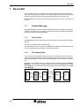
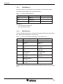
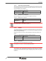
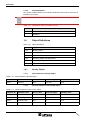
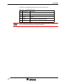
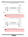
User Manual
Connection to DeviceNet
Part Number:
80 860.642
Version:
1
Date:
12.07.2005
Valid for:
TSwin .net 4.0x
Version
1
Date
12.07.2005
Modifications
First edition
This manual, including all illustrations contained herein, is copyright protected. Use of this manual by any third
party in departure from the copyright provision is forbidden. No part of this manual may be reproduced, translated or electronically or photographically archived or altered without the express written consent from Sütron
electronic GmbH. Violations shall be cause for damage liability.
Sütron electronic reserves the right to make any changes that contribute to technical improvement.
Overall Table of Contents
Overall Table of Contents
1
DeviceNet ................................................................................................................ 1-1
1.1
Explicit Message ....................................................................................... 1-1
1.1.1
Storing Data ......................................................................................... 1-1
1.1.2
Exchanging Data ................................................................................. 1-1
1.1.3
Data Memory ....................................................................................... 1-2
1.1.4
Read Service ....................................................................................... 1-2
1.1.5
Write Service ....................................................................................... 1-3
1.1.6
Fragmentation...................................................................................... 1-4
1.2
Poll I/O Connection ................................................................................... 1-4
1.2.1
Receive Data of the Operating Device (Consumed Data) ................... 1-4
1.2.2
Transmit Data of the Operating Device (Produced Data) .................... 1-4
1.2.2.1
Byte 1 - Initialization....................................................................................................1-5
1.2.2.2
Byte 2 - Control Byte...................................................................................................1-5
1.2.2.3
Byte 3 and Byte 4 - Word Address .............................................................................1-5
1.2.2.4
Byte 5 - Number of Bytes............................................................................................1-6
1.2.3
Module/Network Status........................................................................ 1-6
1.3
Programming ............................................................................................ 1-6
1.3.1
Protocol Parameters ............................................................................ 1-6
1.3.1.1
Baud Rate...................................................................................................................1-6
1.3.1.2
Node Number .............................................................................................................1-6
1.3.1.3
Delay until Connection Set-Up....................................................................................1-7
1.3.1.4
Waiting Time for Response ........................................................................................1-7
1.3.1.5
Attribute ......................................................................................................................1-7
1.3.1.6
Byte Order ..................................................................................................................1-7
1.3.2
Input Syntax ......................................................................................... 1-9
1.3.3
Variables .............................................................................................. 1-9
1.3.4
System Variables ................................................................................. 1-9
1.3.4.1
ComBaudrateA ...........................................................................................................1-9
1.3.4.2
ComHandshakeA......................................................................................................1-10
1.4
Object Definitions.................................................................................... 1-10
1.4.1
Identity Object .................................................................................... 1-10
1.4.1.1
Class Attribute of Identity Object ..............................................................................1-10
1.4.1.2
Instance Attribute of the Identity Object....................................................................1-10
1.4.1.3
Instance Service of the Identity Object .....................................................................1-11
1.4.1.4
Message Router Object ............................................................................................1-11
1.4.2
DeviceNet Object ............................................................................... 1-11
1.4.2.1
Class Attribute of the DeviceNet Object ...................................................................1-11
1.4.2.2
Instance Attribute of the DeviceNet Object...............................................................1-11
1.4.2.3
Instance Service of the DeviceNet Object ................................................................1-11
1.4.3
Assembly Object ................................................................................ 1-12
1.4.3.1
Class Attribute of the Assembly Object ....................................................................1-12
1.4.3.2
Instance 1 Attribute - Static Input - of the Assembly Object .....................................1-12
1.4.3.3
Instance 2 Attribute - Static Output - of the Assembly Object...................................1-12
1.4.4
Connection Object ............................................................................. 1-12
1.4.4.1
Class Attribute of the Connection Object..................................................................1-12
1.4.4.2
Instance Attribute of the Connection Object .............................................................1-12
i
Overall Table of Contents
1.4.4.3
Instance Service of the Connection Object .............................................................. 1-13
1.4.5
BT Object ........................................................................................... 1-13
1.4.5.1
Instance Service of the BT Object ............................................................................ 1-13
1.5
Format of the Explicit Message............................................................... 1-16
1.6
EDS File .................................................................................................. 1-18
1.7
Physical Interfacing ................................................................................. 1-18
1.7.1
A
ii
DeviceNet, 9 Pin D-SUB .................................................................... 1-18
1.7.1.1
Pin Assignment......................................................................................................... 1-19
1.7.2
DeviceNet, 5 Pin Male Connector Strip ............................................. 1-19
1.7.2.1
Pin Assignment......................................................................................................... 1-20
1.7.3
Cable DeviceNet, 9 Pin D-SUB.......................................................... 1-22
1.7.4
Cable DeviceNet, 5 Pin Male Connector Strip ................................... 1-22
1.8
Error Messages....................................................................................... 1-23
1.9
Applications............................................................................................. 1-24
1.9.1
OMRON DRM 21-V1 ......................................................................... 1-24
1.9.2
Rexroth PPC ...................................................................................... 1-24
1.9.3
Rockwell RS Logix 5555 - 1756 DNB ................................................ 1-25
1.9.4
Rockwell SLC 505 - 1747 SDN/B ...................................................... 1-25
Index ....................................................................................................................... A-1
DeviceNet
1
DeviceNet
The operating device is incorporated into the DeviceNet network as a DeviceNet
slave. The communication between a controller (master or scanner) and the operating device (slave) is based on the Predefined Master/Slave Connection Set.
Explicit Message Connections and Poll I/O Connections are used as Connection Instances.
1.1
Explicit Message
Explicit Messages are used to exchange data between the operating device and the
controller. This requires you to create a function block in the controller which assembles the payload into Explicit Messages.
1.1.1
Storing Data
All data displayed by the operating device are stored in the operating device’s data
memory.
The size of the data memory is 2500 words.
The data memory is word-oriented. The addresses are always word addresses, both
from the operating device's and the controller's perspective.
1.1.2
Exchanging Data
You need to create a program (function block) in the controller which is used to establish a data exchange between the operating device and the controller by means
of Explicit Messages. For this, make sure that the data on both devices are consistent.
New data in the controller has to be transferred to the operating device by Explicit
Messages. The controller is informed about new data in the operating device by I/O
Poll Telegram. The controller has to read the data from the operating device by Explicit Message.
Operating Unit (DeviceNet Slave)
read
Display and
Operating
Unit
write
Figure 1-1
Explicit Message
read
write
Data
Memory
Controller / PLC
DeviceNet
Slave
read
write
DeviceNet
Master
Explicit Message
write
Controller
Unit
read
Data exchange, DeviceNet
1-1
DeviceNet
1.1.3
Data Memory
The data memory in the operating device is referred to as the Memory Object.
The Memory Object Address has the following values.
Table 1-1
Memory object addresses
Address
Name
0x8A
Class ID
0x01
Instance ID
0x01
Attribute
Comment
Not Required
The service
–
for a read access is 0x33 and
–
for a write access is 0x35.
1.1.4
Read Service
The following table illustrates the structure of the Explicit Message for the Read service. Each field of the telegram is one byte long.
Table 1-2
Structure of the Explicit Message for the Read service
Byte
Request Telegram
Response Telegram
1
MAC ID
MAC ID
2
Service ID
0x33
Service ID
0xB3
3
Class ID
0x8A
1st Data Word
Low Byte
4
Instance ID
0x01
1st Data Word
High Byte
5
Word Address
Low Byte
2nd Data Word
Low Byte
6
Word Address
High Byte
2nd Data Word
High Byte
7
Number of Bytes
Low Byte
8
Number of Bytes
High Byte
The word address corresponds to the offset within the data memory in the operating
device.
1-2
DeviceNet
The byte order for the
–
word address,
–
number of bytes and
–
data word
can be specified in the communication parameters.
See chapter “Byte Order“ on page 1-7.
1.1.5
Write Service
The following table illustrates the structure of the Explicit Message for the Write service. Each field of the telegram is one byte long.
Table 1-3
Structure of the Explicit Message for the Write service
Byte
Request Telegram
Response Telegram
1
MAC ID
MAC ID
2
Service ID
0x35
Service ID
0xB5
3
Class ID
0x8A
4
Instance ID
0x01
5
Word Address
Low Byte
6
Word Address
High Byte
7
1st Data Word
Low Byte
8
1st Data Word
High Byte
9
2nd Data Word
Low Byte
10
2nd Data Word
High Byte
The word address corresponds to the offset within the data memory in the operating
device.
1-3
DeviceNet
The byte order for the
–
word address,
–
number of bytes and
–
data word
can be specified in the communication parameters.
See chapter “Byte Order“ on page 1-7.
1.1.6
Fragmentation
By means of fragmentation, up to 384 bytes can be transferred in one explicit message.
1.2
Poll I/O Connection
On account of the EDS data, the Poll I/O Connection is installed automatically between the DeviceNet master and the operating device. With this connection, 2 bytes
are transferred cyclically from the controller’s OUT area to the operating device and
5 bytes are transferred from the operating device to the IN area of the controller.
1.2.1
Receive Data of the Operating Device (Consumed Data)
The Consumed Connection Size is 2 bytes.
Table 1-4
Structure of the Consumed Data
Byte
Designation
1
Initialization
2
Control Byte
1.2.2
Transmit Data of the Operating Device (Produced Data)
The Produced Connection size is 5 bytes.
Table 1-5
1-4
Structure of the Produced Data
Byte
Designation
1
Initialization
2
Control Byte
3
Word Address - Low Byte
4
Word Address - High Byte
5
Number of Altered Bytes
DeviceNet
1.2.2.1
Byte 1 - Initialization
During the boot process, the operating device writes the value 0x00 into its Produced
Data. Thus, the controller needs to initialize the entire data memory in the operating
device once.
Initialization means that all variable values in the data memory of the operating device are set the same as in the controller. When this process is completed, the controller writes the value 0xC3 into the Consumed Data.
The operating device acknowledges by writing the value 0xC3 into the Produced
Data.
After the boot process, the operating device waits for the initialization to complete,
before it accesses the data memory. If the initialization is not performed within the
time period set for the Delay until Connection Setup, the following message appears.
Figure 1-2
Message NO INITIALIZATION BY PLC
To remove the message, press OK, the Help key or a key that calls up another
screen.
1.2.2.2
Byte 2 - Control Byte
During initialization, the control byte is set to the value 0x00.
Bit 0:
Bit 0 is the toggle bit.
After you change a variable on the operating device, bit 0 in the Produced Data toggles.
If the controller detects that bit 0 in the Produced Data and bit 0 in the Consumed
Data do not match, the conroller has to read the changed data of the variable by „Explicit Message“.
Once the read operation is complete, the controller sets the value of bit 0 in the Consumed Data to the same value as that of bit 0 in the Produced Data.
If the controller detects that bit 0 in the Produced Data and bit 0 in the Consumed
Data differ, bit 0 in the Consumed Data must be set to the same value as that of bit
0 in the Produced Data!
If no bit synchronization takes place, the operating device displays the error message
Timeout Error: Code 60, Subcode1“.
Bit 1 to bit 7
Bits 1 to 7 are reserved.
1.2.2.3
Byte 3 and Byte 4 - Word Address
Bytes 3 and 4 in the Produced Data contain the word address starting from which a
variable has changed. The variable can be several bytes long. The controller uses
this word address to selectively read the changed variable from the data memory of
the operating device.
1-5
DeviceNet
1.2.2.4
Byte 5 - Number of Bytes
Byte 5 in the Produced Data contains the number of bytes as the size information for
the changed variable.
1.2.3
Module/Network Status
The operating devices are not equipped with diagnostic LEDs for DeviceNet status
indication.
To indicate the module/network status, use the system variable ComBaudrateA instead.
See chapter “ComBaudrateA“ on page 1-9.
1.3
Programming
1.3.1
Protocol Parameters
With the protocol parameters, you can adapt the communication of the controller
used.
1.3.1.1
Baud Rate
This parameter specifies the communication rate.
Table 1-6
Baud rate
Configurable Values
(kBaud)
Default Value
125
X
250
500
1.3.1.2
Node Number
Use the node number to set the MAC ID for the operating device.
Table 1-7
1-6
Node number
Configurable Values
Default Value
0 to 63
0
DeviceNet
1.3.1.3
Delay until Connection Set-Up
Specify this value to set the period of time the operating device waits before it sends
the first Duplicate MAC ID Check Request Message. Messages arriving before this
time has elapsed are not evaluated.
Table 1-8
Delay until connection set-up
Configurable Values
Default Value
5 s to 255 s
5s
1.3.1.4
Waiting Time for Response
Specify a waiting time for the Produced Data toggle bit monitoring.
Table 1-9
Waiting time for response
Configurable Values
Default Value
0 ms, 50 ms to
65000 ms
500 ms
See chapter “Byte 2 - Control Byte“ on page 1-5.
1.3.1.5
Attribute
The Attribute parameter is not required in the Explicit Message to access the Memory
Object. Some controllers do, however, force and transfer the Attribute parameter to
generate an Explicit Message.
In this case, select the check box: Explicit Message Contains the Parameter 'Attribute'.
Table 1-10
Explicit Message contains the Attribute parameter
Configurable Values
Default Value
OFF
ON
1.3.1.6
X
Byte Order
The byte order for the DeviceNet protocol is Low-High.
See Appendix J in Volume 1 of the DeviceNet Specification.
The experience of some users has shown that some controllers do not use this byte
order. In these cases, a byte-swap must be performed in the controller. For ease of
programming, the user also has the option of swapping the byte order in the operating device.
1-7
DeviceNet
Select two selection fields depending on the actual byte order:
Table 1-11
Byte order
Configurable Values
Default Value
Address/Length LowHigh
X
Data Low-High
X
Address/Length HighLow
Data High-Low
1-8
DeviceNet
1.3.2
Input Syntax
The following image illustrates the structure of the input syntax for variables in the
programming software.
W
Number
DW
Figure 1-3
Syntax diagram
1.3.3
Variables
h
Number
The variable addresses specify an offset in the data memory of the operating device.
Table 1-12
Addresses in the data memory of the operating device
Variable Name
Address
Word Access to Address 127
W 127
Word Access to the Highest Address
W 2500
Double-Word Access to Address 371
DW 371
Double-Word Access to the Highest Address
DW 2499
Bit Access to Bit 5 in Address 500
Bit Field Access to Bit 3 - Bit 12 in Address 1500
1.3.4
Low Byte
High Byte
W 500
5
5
W 1500
3
12
System Variables
Since the operating devices do not have diagnostic LEDs, you need to use system
variables to indicate specific DeviceNet statuses. You can create these system variables within any screen as output variables. To do so, select the representation type
Selection Text and link the variable with a text list containing a text string for each
status.
1.3.4.1
ComBaudrateA
This system variable can be used to indicate the statuses of the module/network
LED.
Table 1-13
Statuses of the module/network LED
Value
Text
Meaning
0
LED Off
1
LED Green
Device is Assigned
2
LED Flashes Green
DUP_MAC_ID Test is Okay
But a Connection is Not Established
3
LED Flashes Red
Connection Terminated After
a Time Delay
4
LED Red
BUS-OFF Status
5
LED Flashes Red And Green
DUP_MAC_ID Error
1-9
DeviceNet
1.3.4.2
ComHandshakeA
This system variable allows you to indicate whether the data memory has been initialized by the master.
See chapter “Byte 1 - Initialization“ on page 1-5.
Table 1-14
Table 1-16
Initialization states of the data memory
Value
Status
0
Not initialized
1
Initialized
1.4
Object Definitions
Table 1-15
Object definitions
Class ID
Object Name
0x01
Identity Object
0x02
Message Router (Not Supported)
0x03
DeviceNet Object
0x04
Assembly Object (Not Supported)
0x05
Connection Object
0x8A
BT Object
1.4.1
Identity Object
1.4.1.1
Class Attribute of Identity Object
Class Attribute of Identity Object
Attribute ID
Attribute Name
Access Rule
Data Size (Byte)
Attribute Value
0x01
Revision
Get
2 (6-2.2)
0x01
1.4.1.2
Table 1-17
Instance Attribute of the Identity Object
Instance Attribute of the Identity Object
Attribute ID
Attribute Name
Access Rule
Data Size (Byte)
Attribute Value
0x01
Vendor ID
Get
2 (6-2.2)
0x238
0x02
Device Type
Get
2
0x00
0x03
Product Code
Get
2
0x01
0x04
Revision
Get
2
0x0101 (1.001)
1-10
DeviceNet
Table 1-17
Instance Attribute of the Identity Object
Attribute ID
Attribute Name
Access Rule
Data Size (Byte)
0x05
Status
Get
2
0x06
Serial Number
Get
4
0x01
0x07
Product Name
Get
32
DeviceNet For BT Series
1.4.1.3
Table 1-18
Attribute Value
Instance Service of the Identity Object
Instance Service of the Identity Object
Service ID
Service Name
Description
0x0E
Get_Attribute_Single
Returns the Contents of the Specific Attribute
0x05
Reset
Invoke the Reset Service in the BT
1.4.1.4
Message Router Object
This object is not supported.
Table 1-19
1.4.2
DeviceNet Object
1.4.2.1
Class Attribute of the DeviceNet Object
Class Attribute of the DeviceNet Object
Attribute ID
Attribute Name
Access Rule
Data Size (Byte)
Attribute Value
0x01
Revision ID
Get
1 (5-5.3)
0x02
1.4.2.2
Table 1-20
Instance Attribute of the DeviceNet Object
Instance Attribute of the DeviceNet Object
Attribute ID
Attribute Name
Access Rule
Data Size (Byte)
0x01
MAC ID
Get
1 (5-5.3)
0x02
BaudRate
Get
1 (5-5.3)
0x05
Allocation
Information
Get
1 (5-5.3)
1.4.2.3
Table 1-21
Attribute Value
Instance Service of the DeviceNet Object
Instance Service of the DeviceNet Object
Service ID
Service Name
Description
0x0E
Get_Attribute_Single
Read attribute
0x4B
Allocation Master/Slave
Connection Set
Request to use predefined master/slave connection set
0x4C
Release Group 2 Identifier
Set
Release desired connection
1-11
DeviceNet
Table 1-22
1.4.3
Assembly Object
1.4.3.1
Class Attribute of the Assembly Object
Class Attribute of the Assembly Object
Attribute ID
Attribute Name
Access Rule
Data Size (Byte)
Attribute Value
0x01
Revision
Get
1
0x02
1.4.3.2
Table 1-23
Instance 1 Attribute - Static Input - of the Assembly Object
Instance 1 Attribute - Static Input - of the Assembly Object
Attribute ID
Attribute Name
Access Rule
Data Size (Byte)
0x03
Set Data
Get
5
1.4.3.3
Table 1-24
Instance 2 Attribute - Static Output - of the Assembly Object
Instance 2 Attribute - Static Output - of the Assembly Object
Attribute ID
Attribute Name
Access Rule
Data Size (Byte)
0x03
Set Data
Get
2
Table 1-25
Attribute Value
Attribute Value
1.4.4
Connection Object
1.4.4.1
Class Attribute of the Connection Object
Class Attribute of the Connection Object
Attribute ID
Attribute Name
Access Rule
Data Size (Byte)
Attribute Value
0x01
Revision
Get
1
0x01
1.4.4.2
Table 1-26
Instance Attribute of the Connection Object
Instance Attribute of the Connection Object
Attribute ID
Attribute Name
Access
Rule
Data Size
(Byte)
Value
Expl.
Value
IO-Poll
0x01
State
Get
1
0x02
Instance Type
Get
1
0
1
0x03
TransportClass_Trigger
Get
1
0x38
0x82
0x04
Produced Connection ID
Get
2
0x05
Consumer Connection ID
Get
2
0x06
Initial Comm Characteristics
Get
1
0x21
0x01
0x07
Produced Connection Size
Get
2
0xFFFF
5
0x08
Consumed Connection Size
Get
2
0xFFFF
2
0x09
Expected Packed Rate
Get/Set
2
Default
Default
0x0C
Watchdog Timeout Action
Get/Set
1
Default
Default
0x0D
Produced Connection Path Length
Get
2
0
6
1-12
DeviceNet
Table 1-26
Instance Attribute of the Connection Object
Attribute ID
Attribute Name
Access
Rule
Data Size
(Byte)
Value
Expl.
Value
IO-Poll
0x0E
Produced Connection Length
Get
6
0
20 04 24
01 30 03
0x0F
Consumed Connection Path Length
Get
2
0
6
0x10
Consumed Connection Path
Get
6
0
20 04 24
02 30 03
1.4.4.3
Table 1-27
Instance Service of the Connection Object
Instance Service of the Connection Object
Service ID
Service Name
Description
0x0E
Get_Attribute_Single
Read Attribute
0x10
Set_Attribute_Single
Write Attribute
Table 1-28
1.4.5
BT Object
1.4.5.1
Instance Service of the BT Object
Instance Service of the BT Object
Service ID
Service Name
Description
0x33
Block StringN Read
Read Data by Each Data Unit
0x35
Block StringN Write
Write Data by Each Data Unit
Service ID = 0x33
(Block StringN Read)
Table 1-29
Request without Attribute parameter
Byte
Designation
1
MAC ID
2
Service ID (0x33)
3
Class ID (0x8A)
4
Instance ID (0x01)
5
Word Address Low Byte *
6
Word Address High Byte *
7
Word Number of Bytes Low Byte *
8
Word Number of Bytes High Byte *
Table 1-30
Response without Attribute parameter
Byte
Designation
1
MAC ID
2
Service ID (0xB3)
3
1st Data Word Low Byte **
1-13
DeviceNet
Table 1-30
Response without Attribute parameter
Byte
Designation
4
1st Data Word High Byte **
5
2nd Data Word Low Byte **
6
2nd Data Word High Byte **
Table 1-31
Request with Attribute parameter
Byte
Designation
1
MAC ID
2
Service ID (0x33)
3
Class ID (0x8A)
4
Instance ID (0x01)
5
Attribute (0x01)
6
Word Address Low Byte *
7
Word Address High Byte *
8
Word Number of Bytes Low Byte *
9
Word Number of Bytes High Byte *
Table 1-32
Response with Attribute parameter
Byte
Designation
1
MAC ID
2
Service ID (0xB3)
3
1st Data Word Low Byte **
4
1st Data Word High Byte **
5
2nd Data Word Low Byte **
6
2nd Data Word High Byte **
Service ID = 0x35
(Block StringN Write)
Table 1-33
1-14
Request without Attribute parameter
Byte
Designation
1
MAC ID
2
Service ID (0x35)
3
Class ID (0x8A)
4
Instance ID (0x01)
5
Word Address Low Byte *
6
Word Address High Byte *
7
1st Data Word Low Byte **
DeviceNet
Table 1-33
Request without Attribute parameter
Byte
Designation
8
1st Data Word High Byte **
9
2nd Data Word Low Byte **
10
2nd Data Word High Byte **
Table 1-34
Response without Attribute parameter
Byte
Designation
1
MAC ID
2
Service ID (0xB5)
Table 1-35
Request with Attribute parameter
Byte
Designation
1
MAC ID
2
Service ID (0x35)
3
Class ID (0x8A)
4
Instance ID (0x01)
5
Attribute (0x01)
6
Word Address Low Byte *
7
Word Address High Byte *
8
1st Data Word Low Byte **
9
1st Data Word High Byte **
10
2nd Data Word Low Byte **
11
2nd Data Word High Byte **
Table 1-36
Response with Attribute parameter
Byte
Designation
1
MAC ID
2
Service ID (0xB5)
* Depends on the protocol parameter Byte Order for Address/Length.
** Depends on the protocol parameter Byte Order for Data.
1-15
DeviceNet
1.5
Table 1-37
Format of the Explicit Message
Format of the Explicit Message
Class ID
(1 Byte)
Service ID
(1 Byte)
Instance ID
(1 Byte)
Service Data
Attribute ID
(1 Byte)
Data
(n Byte)
0x01
(Identity
Object)
0x0E (Get)
0x01
0x01
Vendor ID
Get Attribute Single
Vendor ID
0x02
Product Type
Get Attribute Single
Product Type
0x03
Product
Code
Get Attribute Single
Product Code
0x04
Vendor
Revision
Get Attribute Single
Vendor Revision
0x05
ID Status
Get Attribute Single
ID Status
0x06
Serial
Number
Get Attribute Single
Serial Number
0x07
Product
Name
Get Attribute Single
Product Name
0x03
(DeviceNet Object)
0x04
(Assembly Object)
1-16
Service Name
0x05
0x01
N/A or 0x01
RESET
0x0E (Get)
0x01
0x01
MAC ID
Get Attribute Single MAC ID
0x02
Baud Rate
Get Attribute Single
Baud Rate
0x05
Allocation
Information
Get Attribute Single
Allocation Information
0x0E (Get)
0x64
IN DATA
0x0E (Get)
0x65
OUT DATA
IN DATA
OUT DATA
DeviceNet
Table 1-37
Format of the Explicit Message
Class ID
(1 Byte)
Service ID
(1 Byte)
Instance ID
(1 Byte)
Service Data
Attribute ID
(1 Byte)
Data
(n Byte)
0x05
(Connection Object)
0x0E (Get)
0x01 (Explicit
Message)
0x02 (Polled
I/O)
0x01
State
Get Attribute Single State
0x02
Instance
Type
Get Attribute Single
Instance Type
0x03
Transport
Class Trigger
Get Attribute Single
Transport Class Trigger
0x04
Produced
Connection
ID
Get Attribute Single
Produced Connection ID
0x05
Consumed
Connection
ID
Get Attribute Single
Consumed Connection ID
0x06
Initial Comm.
Characteristics
Get Attribute Single
Initial Comm. Characteristics
0x07
Produced
Connection
Size
Get Attribute Single
Produced Connection Size
0x08
Consumed
Connection
Size
Get Attribute Single
Consumed Connection Size
0x09
Expected
Packet Rate
Get Attribute Single
Packet Rate
0x0C
Watchdog
Timeout
Action
Get Attribute Single
Watchdog Timeout Action
0x0D
Produced
Connection
Path Length
Get Attribute Single
Produced Connection Path
Length
0x0E
Produced
Connection
Path
Get Attribute Single
Produced Connection Path
0x0F
Consumed
Connection
Path Length
Get Attribute Single
Consumed Connection Path
Length
0x10
Consumed
Connection
Path
Get Attribute Single
Consumed Connection Path
0x8A (PT
Object)
Service Name
0x33
0x1
Service Data
Block String Read
0x35
0x1
Service Data
Block String Write
0x33
0x1
0x0
Data
Block String Read *
0x35
0x1
0x0
Data
Block String Write *
* Alternative, depends on the communication parameter Attribute.
1-17
DeviceNet
1.6
EDS File
The EDS file ensures that the Poll I/O Connection is automatically installed between
the DeviceNet master and operating device.
1.7
Physical Interfacing
1.7.1
DeviceNet, 9 Pin D-SUB
The connectors on the operating device and the cable connectors for the connection
to the DeviceNet bus must comply with the DeviceNet connector profile.
Table 1-38
D-SUB connector profile for DeviceNet
Parameter
Specification
Male Connector Strip (X2.1)
Number of Pins
9
Tension Nut
None
Rotation
None
Standards
D-SUB DIN41652 / CECC 75301-802
Contact Assignment
CAN_H = 7
CAN_L = 2
DRAIN = Housing
Male Connector Strip (X2.2)
Number of Female Connectors
9
Tension Nut
None
Rotation
None
Standards
D-SUB DIN41652 / CECC 75301-802
Contact Assignment
CAN_H = 7
CAN_L = 2
DRAIN = Housing
Physical Properties
Contact Surface
Gold-plated Copper-alloy or
Gold-plated Palladium-Nickel
Lifetime of Contacts
>500 Plug-in Cycles
Electrical Properties
Operating Voltage
>25 V
Current Carrying Capacity
>5 A
Contact Resistance
Nominal = <10 mOhm
Maximum = 20 mOhm
IEC 60512 Test 2A Millivolt Level Method
Ambient Conditions
1-18
DeviceNet
Table 1-38
D-SUB connector profile for DeviceNet
Parameter
Specification
Water Resistance
No Information Provided
Oil Resistance
No Information Provided
Ambient Temperature
Operation
–55 °C to +105 °C
Ambient Temperature
Storage
–55 °C to +105 °C
1.7.1.1
Pin Assignment
Figure 1-4
9 pin D-SUB female connector strip
Connector in the terminal: 9 pin D-SUB female connector strip.
Table 1-39
Pin assignment CAN
Pin
Designation
Function
1
nc
Not Connected
2
CAN_L
CAN_L Bus Line (Dominant LOW)
3
CAN_GND
CAN Ground
4
nc
Not Connected
5
nc
Not Connected
6
CAN_GND
CAN Ground
7
CAN_H
CAN_H Bus Line (Dominant HIGH)
8
nc
Not Connected
9
nc
Not Connected
1.7.2
DeviceNet, 5 Pin Male Connector Strip
The connectors on the operating device and the cable connectors for the connection
to the DeviceNet bus must comply with the DeviceNet connector profile.
Table 1-40
5 pin male connector strip profile for DeviceNet
Parameter
Specification
Male Connector Strip
Number of Pins
5
Tension Nut
None
Rotation
None
Standards
Figure on Inquiry
1-19
DeviceNet
Table 1-40
5 pin male connector strip profile for DeviceNet
Parameter
Specification
Contact Assignment
nc = 1 (Not Connected)
CAN_L = 2
Drain = 3
CAN_H = 4
nc = 5 (Not Connected)
Female Connector Strip
Number of Pins
5
Tension Nut
None
Rotation
None
Standards
Figure on Inquiry
Contact Assignment
nc = 1 (Not Connected)
CAN_L = 2
Drain = 3
CAN_H = 4
nc = 5 (Not Connected)
Physical Properties
Contact Surface
30 Micro Inch Gold Minimum Over 50 Micro
Inch Nickel Minimum or
5 Micro Inch Gold Minimim Over 20 Micro
Inch Palladium-Nickel Minimum Over 50
Micro Inch Nickel,
All Gold Must be 24 Karat
Lifetime of Contacts
100 Insertion-Extractions
Electrical Properties
Operating Voltage
25 Volt Minimum
Current Carrying Capacity
8 Ampere Minimum
Contact Resistance
Nominal: Less than 1 mOhm
Maximum: 5 mOhm Over Life
Ambient Conditions
1-20
Water Resistance
None
Oil Resistance
Nne
Ambient Temperature
Operation
–40 °C to +70 °C Full Power With Linear
Derating to 0 Ampere at 80 °C
Ambient Temperature
Storage
–40 °C to +85 °C
1.7.2.1
Pin Assignment
Figure 1-5
5 pin connector
DeviceNet
Connector in the operating terminal: 5 pin male connector strip.
Table 1-41
Pin assignment CAN
Pin
Designation
Function
1
nc
Not Connected
2
CAN_L
CAN_L Bus Line (Dominant LOW)
3
Drain
Shield
4
CAN_H
CAN_H Bus Line (Dominant HIGH)
5
nc
Not Connected
For the connection, use a 5 pin connector with gold-plated contacts. A suitable connector can be obtained directly from Sütron electronic.
1-21
DeviceNet
1.7.3
Cable DeviceNet, 9 Pin D-SUB
Operating device
CAN_H
CAN_L
CAN_GND
Next
DeviceNet
participant
7
BN
BN
7
2
WH
WH
2
3
GNYE
GNYE
3
D-SUB
male connector
9 pin
CAN_H
CAN_L
CAN_GND
D-SUB
female connector
9 pin
Both ends of the shield are connected to the metallic housing.
Contrary to the recommendations made in the CiA Draft Standard 102, the cable is
only equipped with the wires needed to meet the current communication requirements.
1.7.4
Cable DeviceNet, 5 Pin Male Connector Strip
Operating device
CAN_H
CAN_L
DRAIN
Next
DeviceNet
participant
4
BN
BN
4
2
WH
WH
2
3
GNYE
GNYE
3
Male connector
5 pin
CAN_H
CAN_L
DRAIN
Female connector
5 pin
Both ends of the shield are connected to pin 3.
Contrary to the recommendations made in the CiA Draft Standard 102, the cable is
only equipped with the wires needed to meet the current communication requirements.
1-22
DeviceNet
1.8
Error Messages
Error messages are displayed on the operating device along with a code and subcode. Error messages are composed as follows.
Communication Error
Table 1-42
Code
Code
XXXXX
Subcode
XXXXX
Retries
XXXXX
DeviceNet error messages
Subcode
50
Error Type
Possible Cause
Hardware error
1
CAN controller error (stuff error)
2
CAN controller error (form error)
3
CAN controller error (acknowledge error)
Device is not connected to
the bus.
4
CAN controller error (bit 1 Error)
Short-circuit between the
CAN_L and CAN_H line.
5
CAN controller error (bit 0 error)
Short-circuit between the
CAN_L and CAN_H line.
6
Error from CAN controller (CRC error)
60
Data exchange error
1
Toggle bit in the control byte is not processed by the
controller or the DeviceNet master.
If the controller detects that
the toggle bit in the Produced
Data and the toggle bit in the
Consumed Data differ, the
toggle bit in the Consumed
Data must be set to the same
value as that of the toggle bit
in the Produced Data.
2
Changed data in the operating device is not read by
controller
Although transferred by
Poll I/O the controller does
not read from the assigned
address
1-23
DeviceNet
1-24
1.9
Applications
1.9.1
OMRON DRM 21-V1
Figure 1-6
DeviceNet for OMRON DRM 21-V1
1.9.2
Rexroth PPC
Figure 1-7
Protocol parameters for Rexroth PPC
DeviceNet
1.9.3
Rockwell RS Logix 5555 - 1756 DNB
Figure 1-8
DeviceNet for Rockwell RS Logix 5555 - 1756 DNB
1.9.4
Rockwell SLC 505 - 1747 SDN/B
Figure 1-9
DeviceNet for Rockwell SLC 505-1747 SDN/B
1-25
DeviceNet
1-26
Index
A Index
C
Cable
DeviceNet 5 pin male connector strip ..... 1-22
DeviceNet 9 pin D-SUB .......................... 1-22
D
DeviceNet ......................................................... 1-1
Explicit Message ....................................... 1-1
Format ................................................ 1-16
Module/network status.............................. 1-6
Object definitions .................................... 1-10
Poll I/O connection.................................... 1-4
P
Pin assignment
DeviceNet .................................... 1-19, 1-20
Protocol parameters
DeviceNet ................................................. 1-6
V
Variables ........................................................... 1-9
A-1
Index
A-2
Sütron electronic GmbH
Kurze Straße 29
D-70794 Filderstadt
Phone: 0049 711 / 77098-0
Fax:
0049 711 / 77098-60
E-mail: [email protected]
Internet: www.suetron.com