1
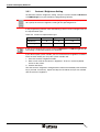
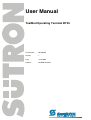
User Manual
TesiMod Operating Terminal BT35
Part Number:
80 860.663
Version:
1
Date:
17.08.2005
Valid for:
BT35EM, BT35ET
Version
1
Date
17.08.2005
Modifications
First Edition
This manual, including all illustrations contained herein, is copyright protected. Use of this manual by any third
party in departure from the copyright provision is forbidden. No part of this manual may be reproduced, translated or electronically or photographically archived or altered without the express written consent from Sütron
electronic GmbH. Violations shall be cause for damage liability.
Sütron electronic reserves the right to make any changes that contribute to technical improvement.
Overall Table of Contents
Overall Table of Contents
1
Important Notes ....................................................................................................... 1-1
1.1
2
1.1.1
General Symbols ................................................................................. 1-1
1.1.2
Specific Symbols ................................................................................. 1-1
1.2
Safety Notes ............................................................................................. 1-2
1.3
Intended Use............................................................................................. 1-2
1.4
Target Group............................................................................................. 1-2
Installation and Commissioning ............................................................................... 2-1
2.1
Unpacking the Device ............................................................................... 2-1
2.2
Mounting the Device ................................................................................. 2-1
2.2.1
Front Panel Dimensions ...................................................................... 2-2
2.2.2
Mounting Cutout .................................................................................. 2-3
2.2.3
Side View, Mounting Depth ................................................................. 2-4
2.2.3.1
Standard Device .........................................................................................................2-4
2.2.3.2
Field Bus Device.........................................................................................................2-5
2.3
2.3.1
3
Connecting the Device.............................................................................. 2-6
Supply Voltage 24 V ............................................................................ 2-6
2.4
Switching the Device on............................................................................ 2-8
2.5
Identification.............................................................................................. 2-8
Control and Display Elements ................................................................................. 3-1
3.1
4
Symbols .................................................................................................... 1-1
Keyboard................................................................................................... 3-1
3.1.1
Editing Keys ......................................................................................... 3-2
3.1.2
Control Keys ........................................................................................ 3-3
3.1.3
Special Keys ........................................................................................ 3-4
3.1.4
Function Keys ...................................................................................... 3-5
3.1.4.1
Function Key Arrangement .........................................................................................3-5
3.1.4.2
Slide-in Identification Strips for the Function Keys .....................................................3-5
3.2
User Mode Switch..................................................................................... 3-7
3.3
Display ...................................................................................................... 3-7
3.3.1
Contrast / Brightness Setting ............................................................... 3-8
3.3.2
Default Contrast / Brightness Setting................................................... 3-9
3.3.3
Character Attributes ............................................................................. 3-9
3.3.4
Fonts .................................................................................................... 3-9
Interfaces of the Device ........................................................................................... 4-1
4.1
Standard Interfaces................................................................................... 4-2
4.1.1
TTY / 20 mA Current Loop (X3-SER1) ................................................ 4-3
4.1.1.1
Pin Assignment...........................................................................................................4-3
4.1.1.2
Termination.................................................................................................................4-3
i
Overall Table of Contents
4.1.2
RS485 (X3-SER1)................................................................................ 4-4
4.1.2.1
Pin Assignment........................................................................................................... 4-4
4.1.2.2
Termination................................................................................................................. 4-5
4.1.3
RS232 (X3-SER1)................................................................................ 4-6
4.1.3.1
Pin Assignment........................................................................................................... 4-6
4.1.3.2
Termination................................................................................................................. 4-6
4.1.4
RS232 (X3-SER2)................................................................................ 4-7
4.1.4.1
Pin Assignment........................................................................................................... 4-7
4.2
4.2.1
Pin Assignment........................................................................................................... 4-9
4.2.1.2
Cable ........................................................................................................................ 4-10
4.2.1.3
Termination............................................................................................................... 4-10
4.2.1.4
Diagnostic................................................................................................................. 4-10
4.2.2
DeviceNet (X2.1/X2.2) ....................................................................... 4-11
4.2.2.1
Pin Assignment......................................................................................................... 4-12
4.2.2.2
Cable ........................................................................................................................ 4-13
4.2.2.3
Termination............................................................................................................... 4-13
4.2.2.4
Diagnostic................................................................................................................. 4-13
4.2.3
INTERBUS (X2.1/X2.2)...................................................................... 4-14
4.2.3.1
Pin Assignment......................................................................................................... 4-15
4.2.3.2
Cable ........................................................................................................................ 4-16
4.2.3.3
Diagnostic................................................................................................................. 4-16
4.2.4
INTERBUS OPC LWL (DO1/DI1/DO2/DI2) ....................................... 4-17
4.2.4.1
Connector Pin Assignment ....................................................................................... 4-18
4.2.4.2
Cable ........................................................................................................................ 4-18
4.2.4.3
Diagnostic................................................................................................................. 4-19
4.2.5
MPI (X2) ............................................................................................. 4-20
4.2.5.1
Pin Assignment......................................................................................................... 4-21
4.2.5.2
Cable ........................................................................................................................ 4-22
4.2.5.3
Termination............................................................................................................... 4-22
4.2.5.4
Diagnostic................................................................................................................. 4-22
4.2.6
PROFIBUS-DP (X2)........................................................................... 4-23
4.2.6.1
Pin Assignment......................................................................................................... 4-24
4.2.6.2
Cable ........................................................................................................................ 4-24
4.2.6.3
Diagnostics ............................................................................................................... 4-25
Memory Card .......................................................................................... 4-26
4.3.1
Inserting the Memory Card ................................................................ 4-26
4.3.2
Ejecting the Memory Card ................................................................. 4-26
4.4
ii
CAN (X2.1/X2.2) .................................................................................. 4-8
4.2.1.1
4.3
5
Field Bus Interfaces .................................................................................. 4-8
Shielding D-SUB Connectors.................................................................. 4-27
Maintenance and Servicing......................................................................................5-1
5.1
Maintenance Interval................................................................................. 5-1
5.2
Front Panel................................................................................................ 5-1
5.3
Fuse .......................................................................................................... 5-1
5.4
Battery....................................................................................................... 5-1
5.4.1
Changing the Battery ........................................................................... 5-2
5.4.2
Battery Disposal ................................................................................... 5-3
Overall Table of Contents
6
Technical Data......................................................................................................... 6-1
7
Ordering Data .......................................................................................................... 7-1
A
Index ........................................................................................................................A-1
iii
Overall Table of Contents
iv
Important Notes
1
Important Notes
1.1
Symbols
The symbols in this manual are used to draw your attention on notes and dangers.
1.1.1
General Symbols
Danger
This symbol is used to refer to instructions which, if ignored or not carefully followed
could result in personal injury.
Note
This symbol indicates application tips or supplementary notes.
Reference to source of information
This symbol refers to detailed sources of information on the current topic.
1.1.2
Specific Symbols
The following symbols indicate specific dangers which could result in damage to
equipment or personal injury or even up to the death of the operator.
Danger - Electric Shock
Danger - Corrosive
Danger - Toxic
Danger - Explosive
Danger - Fire
Danger - Infrared Light
Danger - Electrostatic Charge
1-1
Important Notes
1.2
Safety Notes
–
Read this manual carefully before using the operating device. Keep this manual
in a place where it is always accessible to all users.
–
Proper transportation, handling and storage, placement and installation of this
product are prerequisites for its subsequent flawless and safe operation.
–
This user manual contains the most important information for the safe operation
of the device.
–
The user manual, in particular the safety notes, must be observed by all personnel working with the device.
–
Observe the accident prevention rules and regulations that apply to the operating
site.
–
Installation and operation must only be carried out by qualified and trained personnel.
1.3
Intended Use
–
The device is designed for use in the industry.
–
The device is state-of-the art and has been built to the latest standard safety requirements. However, dangerous situations or damage to the machine itself or
other property can arise from the use of this device.
–
The device fulfills the requirements of the EMC directives and harmonized European standards. Any modifications to the system can influence the EMC behavior.
This is a class A device. This device may cause radio interference in residential areas. In this case, the user may be required to introduce appropriate countermeasures, and to bear the cost of same.
1.4
Target Group
All configuration, programming, installation, commissioning, operating and maintenance work in connection with the automation system must be performed by trained
personnel only (e.g. qualified electricians, electrical engineers, etc.).
The configuration and programming personnel must be familiar with the safety concepts of automation technology.
The operating personnel must have been trained in handling the controller and be
familiar with the operating instructions.
The installation, commissioning and maintenance personnel must have an education
which entitles them to work on automation systems.
1-2
Installation and Commissioning
2
Installation and Commissioning
2.1
Unpacking the Device
Unpack all parts carefully and check the contents for any visible damage in transit.
Also check whether the shipment matches the specifications on your delivery note.
If you notice damages in transit or discrepancies, please contact our sales department immediately.
2.2
Mounting the Device
When installing the device, leave a gap of at least 30 mm (1.181") around the device
to ensure sufficient air circulation.
When the operating device is installed horizontally, please note that additional sources of heat beneath the operating device may result in heat accumulation.
Make sure to allow sufficient heat dissipation!
Comply with the allowable temperature range listed in the technical data for the use
of the operating device!
To ensure the specified degree of protection, make sure that the seal rests flat on the
mounting surface and the fastening screws are uniformly tightened.
The device can be easily and quickly mounted from the front.
1. Insert the device in the mounting cutout from the front.
2. Secure the device with fastening screws.
2-1
Installation and Commissioning
2-2
2.2.1
Front Panel Dimensions
Figure 2-1
Front panel dimensions
Installation and Commissioning
2.2.2
Mounting Cutout
Figure 2-2
Mounting cutout
A Mounting Cutout
B Front Panel
2-3
Installation and Commissioning
2-4
2.2.3
Side View, Mounting Depth
2.2.3.1
Standard Device
Figure 2-3
Side view and mounting depth for the standard device
Installation and Commissioning
2.2.3.2
Field Bus Device
Figure 2-4
Side view and mounting depth for the field bus device
2-5
Installation and Commissioning
2.3
Connecting the Device
2.3.1
Supply Voltage 24 V
The supply voltage is supplied via connector X1.A.
The device can optionally be equipped with an additional connector (X1.B). In this
case, X1.A is looped through to X1.B and can be used to provide power supply to
other components (e.g. bus node). The pin assignment is the same for both connectors.
The maximum continuous current allowed to flow from connector X1.A to X1.B is 5 A.
To avoid an overload, an external protection must be installed (e.g. fusible cut-out).
The device has reverse polarity protection. In case of wrong polarity, the device will
not operate.
This is a protection class I device. For safe operation, safety extra-low voltage
(SELV) in accordance with DIN EN 61131 must be used for the supply voltage.
Connector in the operating device: 3 pin connector Phoenix COMBICON MSTBV
2.5/3-GF
Table 2-1
Pin
Pin assignment supply voltage
Designation
1
Function
Low-Noise Ground
2
0V
Supply Voltage 0 V
3
24 VDC
Supply Voltage 24 VDC
A suitable female connector strip of the type Phoenix COMBICON MSTB 2.5/3-STF
is supplied.
Cables with finely stranded conductors with a minimum cross-section of 0.75 mm²
(18 AWG) and a maximum cross-section of 2.5 mm² (14 AWG) must be used for the
supply voltage.
Hazardous voltages can exist inside electrical installations that can pose a danger to
humans. Coming in contact with live parts may result in electric shock!
Use the following procedure to connect the device to the supply voltage:
1. Strip approx. 30 mm (1.181") off the outer cable sheath and approx. 5 mm
(0.197") off the wires.
Figure 2-5
2-6
Preparing the cable
Installation and Commissioning
2. Fit the wires with wire end ferrules and connect the wires to the connector.
Figure 2-6
Connecting the female connector strip
If shielded connecting cables are used in the supply voltage area, the shield should
be connected to pin 1.
3. Plug the female connector strip onto connector X1.A.
Figure 2-7
Female connector strip is plugged on
4. Secure the female connector strip in place with a screw-type locking to prevent
it from slipping out.
A separate conductor must always be provided for the protective grounding at the
threaded bolt. The conductor must have a minimum cross-section of 1.5 mm² (16
AWG) and must be kept as short as possible.
2-7
Installation and Commissioning
2.4
Switching the Device on
After you applied the supply voltage, a system test is carried out during which the
modules in the operating device are tested and initialized. All status LEDs are activated for a short time. A number of system and error messages can be output by the
system test. If the application memory contains a valid project, the first mask, i.e. the
„Start mask“ or the mask defined in the TSwin language parameters as the Start-up
mask appears on the display.
The „Start mask“ is displayed for 5 seconds. This is a fixed time setting. After this time
has elapsed, the „Main mask“ or the mask defined in the language parameters as the
Main mask appears on the display. This is the first mask of the operator guidance.
When you push any button while the „Start mask“ is displayed, the „Setup mask“ appears. In this mask you define the parameters for the interfaces and the operating
device.
2.5
Identification
You can identify the operating device by the nameplate on the rear.
Figure 2-8
Nameplate (example)
1
Order Number
2
Firmware Version (Version on Delivery)
3
Voltage and Current
4
Serial Number
Depending on the size of the display, you will be able to read various types of information as the operating device is initialized: clock frequency, application memory
size, current firmware version, TSwin version, project name, time, date, number of
compilation runs and a random number.
Because the initialization mask is visible only for a few seconds there is a possibility
to represent this mask for a longer time period.
1. Hold down an arbitrary key at the operating device to generate an error message.
2. Read the firmware version now.
3. Release the key to complete the initialization procedure of the operating device.
2-8
Control and Display Elements
3
Control and Display Elements
3.1
Keyboard
The keys are positioned under an environmental-proof polyester foil. You project the
operating principle of the keys in the programming software.
Figure 3-1
Front view
1
Mounting Hole
2
Front Panel Cover
3
Display
4
Status LED "Data Release"
5
Special Key "Data Release"
6
Editing Key Plus / Minus
7
Special Key "Enter"
8
Special Key "Delete"
9
Editing Keys "Decimal Point"
10 Editing Keys 0 to 9, Alphabet
11 Control Key "Home"
12 Status LED "Help"
13 Special Key "Help"
14 Device Model
3-1
Control and Display Elements
15 Control Keys "Cursor Left, Right, Up, Down"
16 Company Logo
17 Control Key "Page up"
18 Control Key "Page down"
19 Status LED "Acknowledge"
20 Special Key "Acknowledge"
21 Status LED "Print"
22 Special Key "Print"
23 Function Keys F1 to F20
24 Status LED "Function Key"
25 Soft key SK1 to SK20
3.1.1
Editing Keys
The key 0 and ()° is used for changing data in the editor. The (, ) and ° characters
can be entered when configuring the Shift or ShiftCase system variables.
The key 1 and STU is used for changing data in the editor. The characters S, T and
U can be entered when configuring the Shift or ShiftCase system variables.
The key 2 and VWX is used for changing data in the editor. The characters V, W and
X can be entered when configuring the Shift or ShiftCase system variables.
The key 3 and YZ% is used for changing data in the editor. The characters Y, Z and
% can be entered when configuring the Shift or ShiftCase system variables.
The key 4 and JKL is used for changing data in the editor. The characters J, K and
L can be entered when configuring the Shift or ShiftCase system variables.
The key 5 and MNO is used for changing data in the editor. The characters M, N and
O can be entered when configuring the Shift or ShiftCase system variables.
The key 6 and PQR is used for changing data in the editor. The characters P, Q and
R can be entered when configuring the Shift or ShiftCase system variables.
3-2
Control and Display Elements
The key 7 and ABC is used for changing data in the editor. The characters A, B and
C can be entered when configuring the Shift or ShiftCase system variables.
The key 8 and DEF is used for changing data in the editor. The characters D, E and
F can be entered when configuring the Shift or ShiftCase system variables.
The key 9 and GHI is used for changing data in the editor. The characters G, H and
I can be entered when configuring the Shift or ShiftCase system variables.
The key Decimal point and :?! is used for changing data in the editor. The characters :, ? and ! can be entered when configuring the Shift or ShiftCase system variables.
The key Plus and <=> is used for changing data in the editor. The characters <, =
and > can be entered when configuring the Shift or ShiftCase system variables.
The key Minus and \*/ is used for changing data in the editor. The characters \, * and
/ can be entered when configuring the Shift or ShiftCase system variables.
3.1.2
Control Keys
The key Cursor left can be programmed to directly select adjacent I/O masks. In the
editor, it moves the cursor within a variable to the left by one character (character selection).
The key Cursor right can be programmed to directly select adjacent nodes and I/O
masks. In the editor it moves the cursor one character to the right (character selection).
The key Cursor up can be programmed to directly select adjacent nodes and I/O
masks. In the editor it moves the cursor up one variable (variable selection).
The key Cursor down can be programmed to directly select adjacent I/O masks. In
the editor, it moves the cursor downwards to the next variable (variable selection).
3-3
Control and Display Elements
The key Cursor home can be programmed to directly select higher-level nodes and
I/O masks. In the editor it returns the cursor to the first input variable position.
The key Page up is used to page through tables, recipes and messages. The functionality corresponds to the system variable TabPgUp. The key allows data content
towards the top of the table to be viewed.
The key Page down is used to page through tables, recipes and messages. The
functionality corresponds to the system variable TabPgDn. The key allows data content towards the bottom of the table to be viewed.
3.1.3
Special Keys
The key Help always displays the current help text (online help). The help key LED
flashes when a system message is pending. The system message is always displayed in plain-text.
The key Data Release is used to switch from the menu into the editor. The integrated
LED lights up in the editing mode if the external data release has been set. When the
Data Release key is pressed within the editor, the editing mode is exited.
The key Enter is used to conclude data entry. When pressed while in the Startup
Mask, the key switches into the Setup Mask.
The key Delete deletes the character beneath the cursor in the editor. Removes the
selected messages from the data memory.
The key Acknowledge is used as acknowledge key for the message system. The
LED flashes when a acknowledge is required.
The key Print can be used as a soft key to activate various print jobs. The LED
flashes when a print process is active.
3-4
Control and Display Elements
3.1.4
Function Keys
The function of the function keys is freely assignable (with soft key functions). The
function keys can be used either as direct keys for menu control or for triggering a
function in the controller.
The function of the soft keys is freely assignable. The function keys can be used either as direct keys for menu control or for triggering a function in the controller.
3.1.4.1
Function Key Arrangement
Figure 3-2
Arrangement of the function keys
3.1.4.2
Slide-in Identification Strips for the Function Keys
The identifications strips can be replaced when the operating device is built-in or removed. Inserting the strip from the rear side of the front plate does not influence the
specified seal of the operator terminal. A set of identification strips is supplied with
the operator terminal.
3-5
Control and Display Elements
For the labeling use:
3-6
Single pieces, prototypes
Label with a water-resistant pen
Small series
Copying foil (thickness <= 70 µm) with laser
print
Large series
Customer-specific labeled identification
strips
Figure 3-3
Position of the slide-in identifications strips
Figure 3-4
Set of slide-in identifications strips
Control and Display Elements
3.2
User Mode Switch
The user mode switch is installed at the rear of the operating device.
The switch positions for ON or OFF are shown on the user mode switch.
Table 3-1
User mode switch
S1
S2
S3
S4
Function
I
X
–
–
Standard mode with PLC (default upon delivery)
I
X
I
–
Standard mode without PLC
–
I
–
–
Transparent-Mode with start- and stop code of the keys
–
–
–
I
Transparent-Mode without stop code of the keys
I
–
–
I
Activate download (erases the application memory) and
default contrast / brightness setting
I
–
I
I
Activate upload
Legend for table:
I = Switch ON
– = Switch OFF
X = Any switch position
3.3
Display
Danger - Toxic!
If the display is damaged, avoid touching, swallowing or breathing in the liquids or
gases which may leak out!
Danger - Corrosive!
If the display is damaged, avoid touching, swallowing or breathing in the liquids or
gases which may leak out!
The display type differs depending on the operating device model. Depending on the
display version, you can adjust the contrast and brightness.
Table 3-2
Display versions
Display Type
Order no.
Contrast
Setting
Brightness
Adjustment
STN (Monochrome)
BTxxEM/xxxxxx
X
-
TFT
BTxxET/xxxxxx
-
X
3-7
Control and Display Elements
3.3.1
Contrast / Brightness Setting
To define the contrast / brightness setting, set up the system variable LcdContrast
or LcdBackLight in any mask within the programming software.
To do so, follow the instructions listed in the programming software’s help topic „How
do I specify the contrast / brightness setting for the operating device“.
In the programming software, enter the following values as lower and upper limits for
the representation type.
Table 3-3
Values for representation type
System Variable
Lower Limit
Upper Limit
Default Setting
LcdContrast
0
+ 31
+ 16
LcdBackLight
0
+ 15
+8
If you do not configure the system variable LcdContrast or LcdBackLight, the default setting is used when the device is initialized.
If you did set up the system variable, you can set the contrast / brightness as follows.
Enter the mask where you set up the system variable and:
1. Press the contrast / brightness button.
2. Enter a new value for the contrast / brightness. To do so, use the keyboard
shown on the screen.
3. Confirm with Enter.
The new contrast / brightness setting becomes effective immediately after the Enter
key is pressed. If necessary, repeat the steps two and three until you are satisfied
with the contrast / brightness.
3-8
Control and Display Elements
3.3.2
Default Contrast / Brightness Setting
If the contrast / brightness setting is such that it is no longer possible to read the
masks, you can use the user mode switch to reset the contrast / brightness to the
default value.
For the table with the switch positions of the user mode switch, see chapter „User
Mode Switch“.
The switch position for the default contrast / brightness is identical with the „Activate
download via hardware“. The contrast / brightness is reset before a corresponding
message is displayed. The warning will be displayed in a legible manner.
To restore the default contrast / brightness:
1. Switch the device off.
2. Set the switches S1 and S4 of the user mode switch to ON.
3. Switch the device on again.
4. When the warning appears, switch the device off again.
5. Set switch S4 to OFF.
6. Then switch the device on again.
The application will not be lost.
3.3.3
Character Attributes
The following character attributes can be displayed on the device:
–
Normal
–
Underlined
–
Foreground / background color
3.3.4
Fonts
You are able to use the Windows character sets. Further you can use the font "Normal" and the font "Zoom" or create and use your own character sets.
3-9
Control and Display Elements
3-10
Interfaces of the Device
Interfaces of the Device
The device can either be supplied as a standard device or field bus device.
The universal interface X3 combines several interface standards in one connector.
The connector is divided into two channels. The communication channel (SER1) is
operated separately from the channel for the upload/download/logging printer/scanner (SER2).
For the communication channel (SER1), the protocol-specific use only allows one of
the three interface standards to be used.
Depending on the device variant, several interfaces are available to you:
Table 4-1
Device variants
CAN
DeviceNet
INTERBUS
INTERBUS OPC LWL
MPI
PROFIBUS-DP
Available interfaces
TTY / 20mA, RS485,
RS232c (X3-SER1)
Order number
RS232c (X3-SER2)
4
BTxxEx/23xxxx
X
X
-
-
-
-
-
-
BTxxEx/25xxxx
X
-
X
-
-
-
-
-
BTxxEx/39xxxx
X
-
-
X
-
-
-
-
BTxxEx/21xxxx
X
-
-
-
X
-
-
-
BTxxEx/26xxxx
X
-
-
-
-
X
-
-
BTxxEx/24xxxx
X
-
-
-
-
-
X
-
BTxxEx/22xxxx
X
-
-
-
-
-
-
X
4-1
Interfaces of the Device
4.1
Standard Interfaces
Figure 4-1
Rear view TTY / RS485 / RS232
1. Termination Switch (X3-SER1 RS485)
2. Female Connector X3 (TTY/RS485/RS232c)
3. User Mode Switch
4. Connector X1.A (Supply Voltage)
5. Threaded Bolt for Protective Grounding
6. Cable Fastener for Battery
7. Seal
8. Front Panel
9. Warning
10. Mounting Holes
11. Nameplate
12. Reset Key
13. CompactFlash Slot on the Side
4-2
Interfaces of the Device
4.1.1
TTY / 20 mA Current Loop (X3-SER1)
Depending on the wiring, it is possible to connect the interface either as an active or
passive current loop. The transmit line and the receive line are each provided with a
separate 20 mA power source. The compliance voltage is approx. 10 VDC.
The 20 mA power should be supplied by the transmitter unit. This decreases
crosstalk on the signal lines considerably.
In idle state (signal logic 1), a 20 mA current loop can be measured in the cable.
Signal Logic 1
Current Flow 20 mA
Signal Logic 0
Current Flow Interrupted
4.1.1.1
Pin Assignment
Figure 4-2
25 pin D-SUB female connector strip
Connector in the terminal: 25 pin D-SUB female connector strip.
Table 4-2
Pin assignment TTY / 20 mA, passive
Pin
Designation
Function
10
T+
Transmitted Data, Positive Polarity
13
R+
Received Data, Positive Polarity
14
R-
Received Data, Negative Polarity
19
T-
Transmitted Data, Negative Polarity
Table 4-3
Pin assignment TTY / 20 mA, active
Pin
Designation
Function
10
T+
Transmitted Data, Positive Polarity
12
S1+
Power Source 1, Positive Polarity
13
R+
Received Data, Positive Polarity
14
R-
Received Data, Negative Polarity
16
S2+
Power Source 2, Positive Polarity
19
T-
Transmitted Data, Negative Polarity
21
S1-
Current Sink 1, Negative Polarity
24
S2-
Current Sink 2, Negative Polarity
The D-SUB connector strips must be shielded sufficiently.
See chapter “Shielding D-SUB Connectors“ on page 4-27.
4.1.1.2
Termination
For the operation of channel SER1 as a current loop, the termination for the RS485
must be deactivated.
4-3
Interfaces of the Device
4.1.2
RS485 (X3-SER1)
The interface is suitable for point-to-point and for multi-point connections.
The wires belonging together are marked with „A“ and „B“. Some descriptions refer
to the pins with „+“ and „-“ , where A = + and B = -.
Signal Logic 1
UA - UB <= -0.3 V i.e. (UA < UB)
Signal Logic 0
UA - UB >= +0.3 V i.e. (UA > UB)
4.1.2.1
Pin Assignment
Figure 4-3
25 pin D-SUB female connector strip
Connector in the operating terminal: 25-pin D-SUB female connector
Table 4-4
Pin assignment RS422/RS485
Pin
Designation
Function
8
T(A)
Transmitted Data (+)
9
T(B)
Transmitted Data (-)
11
SGND
Signal Ground
22
R(A)
Received Data (+)
23
R(B)
Received Data (-)
The D-SUB connector strips must be shielded sufficiently.
See chapter “Shielding D-SUB Connectors“ on page 4-27.
4-4
Interfaces of the Device
4.1.2.2
Termination
For point-to-point connections, always activate the termination. For multipoint connections, only activate the termination at the cable end.
Figure 4-4
Block diagram termination RS422 / RS485
Table 4-5
Resistor values - termination RS422 / RS485
Designation
Value
R1, R3
510 Ohm
R2
150 Ohm
R4
120 Ohm
The switch positions for ON or OFF are printed onto the termination switch. Only the
specified switch positions are allowed.
Table 4-6
S1
Termination switch
S2
S3
Transmitter
S4
Function
Receiver
I
I
I
I
Termination is ON
–
–
–
–
Termination is OFF
Legend for table:
I = Switch ON
- = Switch OFF
4-5
Interfaces of the Device
4.1.3
RS232 (X3-SER1)
The interface is suitable to establish a point-to-point connection.
4.1.3.1
Pin Assignment
Figure 4-5
25 pin D-SUB female connector strip
Connector in the terminal: 25 pin D-SUB female connector strip.
Table 4-7
Pin assignment RS232
Pin
Designation
Function
6
TD
Transmitted Data
15
CTS
Clear to Send
17
RTS
Request to Send
18
RD
Received Data
25
SGND
Signal Ground
The D-SUB connector strips must be shielded sufficiently.
See chapter “Shielding D-SUB Connectors“ on page 4-27.
4.1.3.2
Termination
For the operation of channel SER1 as a RS232, the termination for the RS485 must
be OFF.
4-6
Interfaces of the Device
4.1.4
RS232 (X3-SER2)
The interface is only designed to be used for downloads, uploads, a scanner or a logging printer because the interface is not electrically isolated.
4.1.4.1
Pin Assignment
Figure 4-6
25 pin D-SUB female connector strip
Connector in the operating device: 25 pin D-SUB female connector strip.
Table 4-8
Pin
Pin assignment RS232
Designation
1
Function
Low-Noise Ground
2
TD
Transmitted Data
3
RD
Received Data
4
RTS
Request to Send
5
CTS
Clear to Send
7
SGND
Signal Ground
The D-SUB connector strips must be shielded sufficiently.
See chapter “Shielding D-SUB Connectors“ on page 4-27.
4-7
Interfaces of the Device
4.2
Field Bus Interfaces
4.2.1
CAN (X2.1/X2.2)
The opto decoupled interface for CAN bus connections is available to integrate the
device into a CAN structure. The CAN bus is a high speed bus in accordance with
ISO-DIS 11898.
Figure 4-7
4-8
Rear view CAN
Interfaces of the Device
1. Female Connector X2.2 (CAN Bus)
2. Female Connector X3 (SER2 RS232c)
3. Connector X2.1 (CAN Bus)
4. User Mode Switch
5. Connector X1.A (Supply Voltage)
6. Threaded Bolt for Protective Grounding
7. Cable Fastener for Battery
8. Seal
9. Front Panel
10. Warning
11. Mounting Holes
12. Nameplate
13. Reset Key
14. CompactFlash Slot on the Side
15. Diagnostics LED
4.2.1.1
Pin Assignment
Figure 4-8
9 pin D-SUB male connector strip and female connector strip
Connector in the terminal: 9 pin D-SUB male and female connector strip (assignment
for male and female connector strip is the same.)
Table 4-9
Pin assignment CAN bus
Pin
Designation
Function
1
nc
Not Connected
2
CAN_L
CAN_L Bus Line (Dominant LOW)
3
CAN_GND
CAN Ground
4
nc
Not Connected
5
nc
Not Connected
6
CAN_GND
CAN Ground
7
CAN_H
CAN_H Bus Line (Dominant HIGH)
8
nc
Not Connected
9
nc
Not Connected
All signal lines are looped through from X2.1 to X2.2. The connecting cables should
be connected to every pin, including the reserved pins. In this way, the cables can
still be used in case of future bus specification extensions.
The D-SUB connector strips must be shielded sufficiently.
See chapter “Shielding D-SUB Connectors“ on page 4-27.
4-9
Interfaces of the Device
4.2.1.2
Cable
A shielded twisted-pair cable (cable type LiYCY-TP) complying with ISO 11898 must
be used.
The cable must have the following characteristics:
Table 4-10
Cable characteristics CAN
Parameters
Value
Impedance
Min.: 108 Ohm
Nom.: 120 Ohm
Max.: 132 Ohm
Specific Resistance
70 mOhm/m
Specific Line Delay
5 ns/m
The maximum cable length depends on the baud rate used.
Table 4-11
Baud rate CAN
Baud rate
Cable length
20 kBit/s
1000 m
125 kBit/s
500 m
250 kBit/s
250 m
500 kBit/s
100 m
1000 kBit/s
25 m
4.2.1.3
Termination
Terminate the CAN bus at both ends by terminating resistors (120 Ohm).
4.2.1.4
Diagnostic
A diagnostics LED is located at the rear of the operating device. The LED shows a
state of the bus system.
Figure 4-9
Arrangement of the CAN diagnostics LED
The diagnostics LED at the operating device has the following functions:
Table 4-12
4-10
Function of the CAN diagnostics LED
Color
State
Function
Green
Off
Terminal Disconnected from Bus
Green
On
Communication Active
Green
Flashing
Sporadic Bus Error
Interfaces of the Device
4.2.2
DeviceNet (X2.1/X2.2)
The opto-decoupled interfaces are available to integrate the device into a CAN structure. The CAN bus is designed as a high speed bus in accordance with ISO-DIS
11898.
Figure 4-10
Rear view DeviceNet
4-11
Interfaces of the Device
1. Female Connector X2.2 (DeviceNet)
2. Female Connector X3 (SER2 RS232c)
3. Connector X2.1 (DeviceNet)
4. User Mode Switch
5. Connector X1.A (Supply Voltage)
6. Threaded Bolt for Protective Grounding
7. Cable Fastener for Battery
8. Seal
9. Front Panel
10. Warning
11. Mounting Holes
12. Nameplate
13. Reset Key
14. CompactFlash Slot on the Side
15. Diagnostics LED
4.2.2.1
Pin Assignment
Figure 4-11
9 pin D-SUB male connector strip and female connector strip
Connector in the terminal: 9 pin D-SUB male and female connector strip (assignment
for male and female connector strip is the same.)
Table 4-13
Pin assignment CAN bus
Pin
Designation
Function
1
nc
Not Connected
2
CAN_L
CAN_L Bus Line (Dominant LOW)
3
CAN_GND
CAN Ground
4
nc
Not Connected
5
nc
Not Connected
6
CAN_GND
CAN Ground
7
CAN_H
CAN_H Bus Line (Dominant HIGH)
8
nc
Not Connected
9
nc
Not Connected
All signal lines are looped through from X2.1 to X2.2. The connecting cables should
be connected to every pin, including the reserved pins. In this way, the cables can
still be used in case of future bus specification extensions.
The D-SUB connector strips must be shielded sufficiently.
See chapter “Shielding D-SUB Connectors“ on page 4-27.
4-12
Interfaces of the Device
4.2.2.2
Cable
A DeviceNet-certified cable must be used.
Table 4-14
Data line DeviceNet
Cable Type
Loop Resistance
Surge Impedance
Capacitance per
Unit Length
2 x 1.1 mm
< 22.6 Ohm/km
120 Ohm
< 39.4 pf/m
2 x 0.6 mm
< 91.8 Ohm/km
120 Ohm
< 39.4 pf/m
The maximum length allowed for spur lines connected to the bus cable is 6 meters.
The overall length of the bus cable including all spur lines is not to exceed the maximum length listed in the table below.
The maximum cable length depends on the baud rate and the cable type used.
Table 4-15
Baud rate DeviceNet
Baud Rate
Cable Type
Cable Length
125 kBit/s
2 x 1.1 mm
500 m
2 x 0.6 mm
100 m
2 x 1.1 mm
250 m
2 x 0.6 mm
100 m
2 x 1.1 mm
100 m
2 x 0.6 mm
100 m
250 kBit/s
500 kBit/s
4.2.2.3
Termination
Terminate the CAN bus at both ends by terminating resistors (120 Ohm).
4.2.2.4
Diagnostic
A diagnostics LED is located at the rear of the operating device. The LED shows the
states of the bus system.
Figure 4-12
Arrangement of the DeviceNet diagnostics LED
The diagnostics LED at the operating device has the following functions:
Table 4-16
Function of the CAN diagnostics LED
Color
State
Function
Green
Off
Terminal Disconnected from Bus
Green
On
Communication Active
Green
Flashing
Sporadic Bus Error
4-13
Interfaces of the Device
4.2.3
INTERBUS (X2.1/X2.2)
The device can be integrated into the INTERBUS using the interfaces available for
INTERBUS connections.
Figure 4-13
4-14
Rear view INTERBUS
Interfaces of the Device
1. Female Connector X2.2 (Remotebus Out)
2. Female Connector X3 (SER2 RS232c)
3. Connector X2.1 (Remotebus In)
4. User Mode Switch
5. Connector X1.A (Supply Voltage)
6. Threaded Bolt for Protective Grounding
7. Cable Fastener for Battery
8. Seal
9. Front Panel
10. Warning
11. Mounting Holes
12. Nameplate
13. Reset Key
14. CompactFlash Slot on the Side
15. Diagnostics LEDs
4.2.3.1
Pin Assignment
Figure 4-14
9 pin D-SUB male connector strip and female connector strip
Connector in the terminal: 9 pin D-SUB male connector strip for remote bus in.
Table 4-17
Pin assignment remote bus in (INTERBUS)
Pin
Designation
Function
1
DO
Data Input
2
DI
Data Output
3
GND
Ground
4
nc
Not Connected
5
nc
Not Connected
6
/DO
Data Input, Inverted
7
/DI
Data Output, Inverted
8
nc
Not Connected
9
nc
Not Connected
Connector in the terminal: 9 pin D-SUB female connector strip for remote bus out.
Table 4-18
Pin assignment remote bus out (INTERBUS)
Pin
Designation
Function
1
DO
Data Output
2
DI
Data Input
3
GND
Ground
4
nc
Not Connected
4-15
Interfaces of the Device
Table 4-18
Pin assignment remote bus out (INTERBUS)
Pin
Designation
Function
5
+5 V
Power Supply +5 VDC
6
/DO
Data Output, Inverted
7
/DI
Data Input, Inverted
8
nc
Not Connected
9
RBST
Remote Bus Status
The D-SUB connector strips must be shielded sufficiently.
See chapter “Shielding D-SUB Connectors“ on page 4-27.
4.2.3.2
Cable
A shielded twisted-pair cable (cable type LiYCY-TP) must be used. The maximum
cable length depends on its use within the INTERBUS topology.
4.2.3.3
Diagnostic
The diagnostics LEDs are located at the rear of the operating device. The LEDs show
the states of the bus system.
Figure 4-15
Arrangement of the INTERBUS diagnostics LEDs
The diagnostics LEDs at the operating device has the following functions:
Table 4-19
Designation
Color
State
Function
RC
Green
On
Remote Bus Check
+5 V
Green
On
Supply Voltage OK
Off
No Supply Voltage
On
Bus Active
Off
Bus Not Active
On
Remote Bus Inactive
BA
RD
4-16
Functions of the INTERBUS diagnostics LEDs
Green
Red
Interfaces of the Device
4.2.4
INTERBUS OPC LWL (DO1/DI1/DO2/DI2)
The device can be integrated into an INTERBUS device bus using the interfaces
available for INTERBUS OPC LWL connection.
Figure 4-16
Rear view INTERBUS OPC LWL
4-17
Interfaces of the Device
1. OPC LWL Interface DO2 (Remotebus Out)
2. Female Connector X3 (SER2 RS232c)
3. OPC LWL Interface DI2 (Remotebus Out)
4. OPC LWL Interface DI1 (Remotebus In)
5. User Mode Switch
6. OPC LWL Interface DO1 (Remotebus In)
7. Connector X1.A (Supply Voltage)
8. Threaded Bolt for Protective Grounding
9. Cable Fastener for Battery
10. Seal
11. Front Panel
12. Warning
13. Mounting Holes
14. Nameplate
15. Reset Key
16. CompactFlash Slot on the Side
17. Diagnostics LEDs
Never look directly into the open end of an optical fiber cable. Infrared light can
cause damage to the retina of the eye. Fit the open ends of an optical fiber cable
and the connections with protective caps. Wear protective goggles.
The sending and receiving units can be rendered unusable by dirt accumulation. For
this reason, place protective caps onto the connections when the units are not used
or are transported! Wear protective goggles.
4.2.4.1
Connector Pin Assignment
The optical fiber interface is designed as a FSMA type 905.
Table 4-20
Assignment INTERBUS OPC LWL
Designation
Function
DO1
Remote Bus In
DI1
Remote Bus In
DO2
Remote Bus Out
DI2
Remote Bus Out
4.2.4.2
Cable
The cables are connected in accordance with the "INTERBUS Fiber Optic Installation Guidelines".
Suitable for optical transmission is a dielectric waveguide with step index refractive
index profile - a polymer fiber with a core diameter of 980 µm and a cladding diameter
of 1000 µm. The F-SMA connector is specified in IEC 874-2 or in DIN 47258, respectively.
The maximum distance between two remote bus users is 50 m (164.042 ft.).
4-18
Interfaces of the Device
4.2.4.3
Diagnostic
The diagnostics LEDs are located at the rear of the operating device. The LEDs show
the states of the bus system.
Figure 4-17
Arrangement of the INTERBUS OPC LWL diagnostics LEDs
The diagnostics LEDs at the operating device has the following functions:
Table 4-21
Functions of the INTERBUS OPC LWL diagnostics LEDs
Designation
Color
State
Function
UL
Green
On
Supply Voltage OK
Off
No Supply Voltage
CC/RC
Green
On
Remote Bus Cable Check
BA
Green
On
Bus Active
Off
Bus Not Active
RD
Yellow
On
Remote Bus Inactive
TR
Green
On
PCP Active
Off
PCP Not Active
Yellow
On
Incoming Optical Fiber Path Not OK
Off
Incoming Optical Fiber Path OK
Yellow
On
Outgoing Optical Fiber Path Not OK
Off
Outgoing Optical Fiber Path OK
FO1
FO2
4-19
Interfaces of the Device
4.2.5
MPI (X2)
The device can be integrated into a Siemens MPI bus structure using the interface
available for Siemens MPI connections.
Figure 4-18
4-20
Rear View MPI
Interfaces of the Device
1. Female Connector X2 (MPI)
2. Female Connector X3 (SER2 RS232c)
3. User Mode Switch
4. Connector X1.A (Supply Voltage)
5. Threaded Bolt for Protective Grounding
6. Cable Fastener for Battery
7. Seal
8. Front Panel
9. Warning
10. Mounting Holes
11. Nameplate
12. Reset Key
13. CompactFlash Slot on the Side
14. Diagnostics LED
4.2.5.1
Pin Assignment
Figure 4-19
9 pin D-SUB female connector strip
Connector in the terminal: 9 pin D-SUB female connector
Table 4-22
Pin assignment MPI
Pin
Designation
Function
1
nc
Not Connected
2
nc
Not Connected
3
RxD/TxD-P
Received Data / Transmitted Data Plus
4
CNTR-P
Repeater Control Signal Plus
5
DGND
Data Transmission Potential
6
VP
Supply Voltage of Terminators Plus
7
nc
Not Connected
8
RxD/TxD-N
Received Data / Transmitted Data Minus
9
CNTR-N
Repeater Control Signal Minus
The D-SUB connector strips must be shielded sufficiently.
See chapter “Shielding D-SUB Connectors“ on page 4-27.
4-21
Interfaces of the Device
4.2.5.2
Cable
Any cable that conforms with the following parameters can be used:
Table 4-23
Cable characteristics MPI
Parameters
Value
Loop Resistance
110 Ohm/km
Capacitance
30 nF/km
Surge Impedance
150 Ohm
The maximum length of one segment is 50 m which cannot be exceeded. This 50 m
applies from the first node to the last node in the segment.
For further information on the installation, please refer to the Siemens manual "SIMATIC S7-400 and M7-400 Programmable Controllers Hardware and Installation,
6ES7498-8AA03-8BA0".
4.2.5.3
Termination
The bus line is terminated at the connector.
For point-to-point connections, always activate the termination. For multi-point connections, only activate the termination at the cable end. For spur lines, always deactivate the termination.
4.2.5.4
Diagnostic
A diagnostics LED is located at the rear of the operating device. The LED shows a
state of the bus system.
Figure 4-20
Arrangement of the MPI diagnostics LED
The diagnostics LED at the operating device has the following function:
Table 4-24
4-22
Function of the MPI diagnostics LED
Color
State
Function
Green
Flashing
Operating Device has the Token
Interfaces of the Device
4.2.6
PROFIBUS-DP (X2)
The interface for PROFIBUS-DP connections is available to integrate the device into
a PROFIBUS-DP structure.
Figure 4-21
Rear view PROFIBUS-DP
4-23
Interfaces of the Device
1. Female Connector X2 (PROFIBUS-DP)
2. Female Connector X3 (SER2 RS232c)
3. User Mode Switch
4. Connector X1.A (Supply Voltage)
5. Threaded Bolt for Protective Grounding
6. Cable Fastener for Battery
7. Seal
8. Front Panel
9. Warning
10. Mounting Holes
11. Nameplate
12. Reset Key
13. CompactFlash Slot on the Side
14. Diagnostics LED
4.2.6.1
Pin Assignment
Figure 4-22
9 pin D-SUB female connector strip
Connector in the operating device: 9 pin D-SUB female connector.
Table 4-25
Pin assignment PROFIBUS-DP
Pin
Designation
Function
1
nc
Not Connected
2
nc
Not Connected
3
RxD/TxD-P
Received Data / Transmitted Data Plus
4
CNTR-P
Repeater Control Signal Plus
5
DGND
Data Transmission Potential
6
VP
Supply Voltage of Terminators Plus
7
nc
Not Connected
8
RxD/TxD-N
Received Data / Transmitted Data Minus
9
CNTR-N
Repeater Control Signal Minus
The D-SUB connector strips must be shielded sufficiently.
See chapter “Shielding D-SUB Connectors“ on page 4-27.
4.2.6.2
Cable
Any PROFIBUS-DP-approved cables specified in the EN 50170 as cable type A can
be used.
4-24
Interfaces of the Device
Table 4-26
Cable characteristics PROFIBUS
Parameters
Value
Impedance
136 to 165 Ohm
Capacitance
< 30 pf/m
Loop Resistance
110 Ohm/km
Wire Gauge
0.64 mm
The maximum cable length depends on the baud rate (DIN EN 19245 Part 3).
Table 4-27
Baud rate PROFIBUS-DP
Baud Rate
Cable Length
187.5 kBit/s
1000 m
500 kBit/s
400 m
1500 kBit/s
200 m
3000 to 12000 kBit/s
100 m
4.2.6.3
Diagnostics
A diagnostics LED is located on the rear of the operating device. The LED shows the
states of the bus system.
The diagnostics LED on the operating device has the following functions:
Table 4-28
Function of the PROFIBUS-DP diagnostics LED
Color
State
Function
Green
ON
Communication Active
4-25
Interfaces of the Device
4.3
Memory Card
You can insert a CompactFlash card on the side of your operating device. The CompactFlash card allows you to exchange projects between the PC and the operating
device.
You can recognize the rear side of a CompactFlash card by the notches on each side
of the card.
Figure 4-23
4.3.1
Rear view of the memory card
Inserting the Memory Card
When you insert the card from the rear side of the operating device, make sure the
front side of the card is visible. Insert the card until it snaps into place.
Figure 4-24
4.3.2
Inserting the memory card
Ejecting the Memory Card
To remove the card, press the ejection button on the operating device.
Figure 4-25
4-26
Ejecting the memory card
Interfaces of the Device
4.4
Shielding D-SUB Connectors
You must shield D-SUB connectors as follows:
Figure 4-26
Shielding D-SUB connectors
1
D-SUB connector
2
Shield
3
Cable clip
4
Cable
The shield must be folded back into a flat position over the cable sheath.
When fastening the cable with the cable clip, as much of the shielding as possible
must be in contact with the housing and sufficient strain relieve must be ensured.
4-27
Interfaces of the Device
4-28
Maintenance and Servicing
5
Maintenance and Servicing
5.1
Maintenance Interval
The following maintenance intervals are recommended for this operating device:
Table 5-1
Maintenance work
Interval
Changing the Battery
4 Years
5.2
Front Panel
Only use a damp cloth to remove any dirt from the front panel.
5.3
Fuse
The semiconductor fuse cannot be replaced!
A semiconductor fuse is used to protect the device. Once the fuse has been tripped,
the device must be disconnected from the supply voltage to allow the semiconductor
fuse to regenerate. At an ambient temperature of 20 °C (68 °F), the regeneration
takes approximately 20 seconds. The higher the ambient temperature, the longer the
regeneration takes.
5.4
Battery
The built-in battery preserves the data in the CMOS-RAM and supplies the real-time
clock. The minimum battery life is 5 years, even under unfavorable operating conditions. When the battery runs down, the message „Change battery“ is generated automatically.
We recommend you change the battery approximately every 4 years as part of the
regular maintenance work. A prepared battery including connector can be obtained
directly from Sütron electronic.
If the „Change battery“ message is detected too late, e.g. the real-time clock stopped
or shows the wrong date, data in the CMOS-RAM may have already been lost. For
this reason, after changing a battery, always check data such as passwords that can
be modified, parameters in the system variables, recipe data sets and entries in the
message system.
5-1
Maintenance and Servicing
5.4.1
Changing the Battery
Batteries must only be changed by authorized and trained experts!
For changing the battery you may only use replacement batteries of
Sütron electronic.
Electrostatic discharge can damage electronic components! Observe the ESD protective measures!
Do not throw lithium batteries into fire, do not heat to 100 °C or higher and do not
recharge. Danger - Explosive!
Do not open lithium batteries. Danger - Toxic!
To ensure that the data in the CMOS-RAM and the time are preserved, it is possible
to change the battery under operating voltage. Observe the safety notes!
1. Disconnect the connector strip of the supply voltage.
2. Remove the threaded bolts of the interfaces (see figure).
3. Remove the screws (see figure) on the rear panel of the device and lift off the
enclosure.
4. Remove the cable fastener securing the battery.
5. Plug in the connector strip of the supply voltage.
6. Disconnect the connector from the battery and remove the dead battery.
7. Plug in the connector of the new battery.
8. Disconnect the connector strip of the supply voltage.
9. Use a cable fastener to attach the new battery to the enclosure.
10. Place the rear panel back onto the device.
11. Carefully tighten the screws of the rear panel and then the threaded bolts of the
interfaces.
12. Plug in the connector strip of the supply voltage.
Figure 5-1
5-2
Screws at the standard device (left) / field bus device (right)
Maintenance and Servicing
5.4.2
Battery Disposal
To prevent short circuitry in the collection boxes, insulate the poles of each battery
with insulation tape or put each single battery into a plastic bag.
You must always return old batteries to a dealer or to a returns depot set up for this
purpose by the public waste disposal body or a licensed battery dealer for recycling.
Only dispose of dead batteries in public or commercial collection boxes. The battery
is drained when the message „Change battery“ appears on the display of the device.
5-3
Maintenance and Servicing
5-4
Technical Data
6
Technical Data
Keyboard
Membrane Keyboard
Short-Stroke Keyboard
with Tactile Feedback
Number of Keys
20
46
Actuator Travel
0.6 mm (0.023")
0.5 mm (0.020")
Actuating Force
3N
2 to 3 N
Switching Cycles
Approx. 3 millions under the
following conditions:
Pressing Element: Test
Plunger (DIN 42115)
Pressing Force: 10 N
Pressing Frequency: 1 Hz
Approx. 1 Million
Display
BT35EM
BT35ET
Type
Monochrome
TFT
Resolution
640 x 480 Pixels
640 x 480 Pixels
Colors
16 Gray Shades
256
Reading Angle
90°
90°
Default Contrast / Default Brightness Setting
By User Mode Switch
By User Mode Switch
LCD Lifetime
100.000 h
100.000 h
Half-Life Backlighting
15.000h
40.000h
Lines
40
40
Characters/Line
80
80
Display Area (H x W)
162 mm x 215 mm (6.378" x
8.465")
162 mm x 215 mm (6.378" x
8.465")
Electrical Data
Supply Voltage
24 V DC (SELV according to DIN EN 61131)
Residual Ripple
10% Maximum
Minimum Voltage
19.2 V
Maximum Voltage
30.2 V
Current Consumption (Field Bus Device)
BT35EM: 0.4 A
BT35ET: 0.7 A
Connected Load
BT35EM: 10 W
BT35ET: 17 W
Fuse
Semiconductor Fuse, Self-Resetting
Protection Against Polarity Reversal
Built-in
6-1
Technical Data
Standard Interfaces
Variable Baud Rates and Data Formats
X3 SER1 TTY / 20 mA
According to CL 2 and DIN 66 348 T1
Transmission Length: 0 - 1000 m (3280.84 ft.), Twisted Pair,
Shielded
Electrically Isolated
X3 SER1 RS485
According to DIN 66259-4
Transmission Length: 0 - 1200 m (3937.01 ft.), Twisted Pair,
Shielded
Electrically Isolated
X3 SER1 RS232c / X3 SER2 RS232c
According to DIN 66259 T1, CCITT V.28
Transmission Length: 0 - 15 m (49.21 ft.), Layer-stranded,
Shielded
X3 SER1: Electrically Isolated
X3 SER2: Not Electrically Isolated
Field Bus Interfaces
Variable Baud Rates and Data Formats
X2.1 / X2.2 CAN Bus
According to ISO 11898
Electrically Isolated
X2.1 / X2.2 DeviceNet
According to ISO 11898
Electrically Isolated
X2.1 / X2.2 INTERBUS
Electrically Isolated
DO1 / DI1 / DO2 / DI2 INTERBUS OPC
Optical Fiber
Electrically Isolated
X2 MPI
Electrically Isolated
X2 PROFIBUS-DP
Electrically Isolated
Central Unit
Central Unit
32-bit RISC CPU
Clock Frequency
74 MHz
Other Characteristics
Watchdog Timer, Real-Time Clock, Temperature Compensation of the Display, Battery Monitoring
Memory
Application Memory
7 MByte Flash
RAM
512 Kbyte Static CMOS-RAM, Battery-Backed
Memory Card
CompactFlash Card
6-2
Technical Data
Connection System
D-SUB Female and Male Connector Strips, 9 Pin and 25 Pin
Female and Male Connector Strips, Phoenix COMBICON, 3 Pin
Connection FSMA Type 905
Environmental Conditions
Operation
0 °C to 50 °C (32 °F to 122 °F)
Storage, Transportation
BT35EM: - 25 °C to + 60 °C (-13°F to 140 °F)
BT35ET: - 25 °C to + 70 °C (-13°F to + 158°F)
Relative Humidity for Operation and Storage
10% to 95%, No Condensation
Application Area
Degree of Pollution 1, Overvoltage Category II
Standards and Guidelines
Interference Immunity
EN 61000-4-2
EN 61000-4-3
EN 61000-4-4
EN 61000-4-5
EN 61000-4-6
EN 61000-6-2
Emitted Interference
EN 50081-1
EN 55022 Limit Value Class A
Equipment Requirements
EN 61131
Storage and Transportation
EN 61131 Part 2
Power Supply
EN 61131 Part 2
Electromagnetic Compatibility
89/336/EEC (Including all Applicable Amendments)
Degrees of Protection
EN 60529
Impact Load, Shocks
EN 60068 Part 2-27
Sinusoidal Vibrations
EN 60068 Part 2-6
Corrosion Protection
IEC 60068
This is a class A device. This device may cause radio interference in residential areas. In this case, the user may be required to introduce appropriate countermeasures, and to bear the cost of same.
6-3
Technical Data
Housing and Front Panel
Housing
Steel Sheet, Galvanized
Front Panel
Aluminium, Anodized
320 mm x 450 mm x 4 mm (H x W x D) (12.598" x 17.716" x
0.157")
Front Panel Cover
Polyester Foil
Seal
Circumferential Rubber Seal on the Rear
Mounting Cutout
296 mm x 426 mm (11.654" x 16.772") - (H x W)
Mounting Depth
Standard Device: Approx. 51 mm (2.008") - (Without Connector)
Field bus Device: Approx. 67 mm (2.638") - (Without Connector)
Field bus Device INTERBUS OPC LWL: Approx. 87 mm
(3.425")
Degrees of Protection
Front: IP65
Rear: IP20
Total Weight
Approx. 2750 g
6-4
Ordering Data
7
Ordering Data
Table 7-1
Accessories
Description
Article No.
CompactFlash Card 16 MB
81152.000
CompactFlash Card 32 MB
81152.032
CompactFlash Adapter for Laptop
81166.000
CompactFlash Adapter for PC
81167.000
25 Pin Download Cable
88175.030
USB-RS232 Converter for Download (Only in Combination with
88175.030)
81215.000
Battery, Prepared with Cable, Connector and Cable Fastener (Type
CR2450)
66757.000
7-1
Ordering Data
7-2
A Index
A
I
Accessories....................................................... 7-1
Identification ...................................................... 2-8
Intended use ..................................................... 1-2
Interface
CAN (X2.1/X2.2) ....................................... 4-8
DeviceNet (X2.1/X2.2) ............................ 4-11
INTERBUS (X2.1/X2.2)........................... 4-14
INTERBUS OPC LWL............................. 4-17
MPI (X2).................................................. 4-20
PROFIBUS-DP (X2)................................ 4-23
RS232 (X3-SER1)..................................... 4-6
RS232 (X3-SER2)..................................... 4-7
RS485 (X3-SER1)..................................... 4-4
TTY / 20 mA (X3-SER1) ........................... 4-3
B
Battery............................................................... 5-1
Battery disposal ................................................ 5-3
Brightness setting ............................................. 3-8
C
Cable
CAN ........................................................ 4-10
DeviceNet ............................................... 4-13
INTERBUS.............................................. 4-16
INTERBUS OPC LWL ............................ 4-18
MPI ......................................................... 4-22
PROFIBUS-DP ....................................... 4-24
Changing the battery......................................... 5-2
Character attributes .......................................... 3-9
Character set
Normal ...................................................... 3-9
Windows ................................................... 3-9
Zoom......................................................... 3-9
Connecting........................................................ 2-6
Connector pin assignment
INTERBUS OPC LWL ............................ 4-18
Contrast setting................................................. 3-8
Control keys ...................................................... 3-3
D
Default brightness setting ................................. 3-9
Default contrast setting ..................................... 3-9
Device variants ................................................. 4-1
Diagnostic
CAN ........................................................ 4-10
DeviceNet ............................................... 4-13
INTERBUS.............................................. 4-16
INTERBUS OPC LWL ............................ 4-19
MPI ......................................................... 4-22
Diagnostics
PROFIBUS-DP ....................................... 4-25
Dimensions
Cutout ....................................................... 2-3
Front panel................................................ 2-2
Mounting depth for standard device ......... 2-4
Mounting depth for the field bus device .... 2-5
Display .............................................................. 3-7
K
Key
Acknowledge............................................. 3-4
Cursor down.............................................. 3-3
Cursor home ............................................. 3-4
Cursor left ................................................. 3-3
Cursor right ............................................... 3-3
Cursor up .................................................. 3-3
Data release.............................................. 3-4
Enter ......................................................... 3-4
Help........................................................... 3-4
Minus ........................................................ 3-3
Page down ................................................ 3-4
Page up..................................................... 3-4
Plus ........................................................... 3-3
Print........................................................... 3-4
Keyboard........................................................... 3-1
L
LcdBackLight..................................................... 3-8
LcdContrast....................................................... 3-8
M
Maintenance...................................................... 5-1
Maintenance interval ......................................... 5-1
Memory card ................................................... 4-26
Mounting ........................................................... 2-1
N
Nameplate......................................................... 2-8
O
E
Ordering data .................................................... 7-1
Editing keys....................................................... 3-2
P
F
Pin assignment
CAN .......................................................... 4-9
DeviceNet ............................................... 4-12
INTERBUS.............................................. 4-15
MPI.......................................................... 4-21
PROFIBUS.............................................. 4-24
Firmware version .............................................. 2-8
Function keys.................................................... 3-5
Fuse .................................................................. 5-1
A-1
RS232 .............................................. 4-6, 4-7
RS422 ....................................................... 4-4
RS485 ....................................................... 4-4
TTY / 20 mA.............................................. 4-3
R
Rear view
TTY / RS485 / RS232 ............................... 4-2
S
Safety notes ...................................................... 1-2
Servicing ........................................................... 5-1
Slide-in identifications strips.............................. 3-5
Special keys ...................................................... 3-4
Standards.......................................................... 6-3
Supply voltage 24 V .......................................... 2-6
Switching on...................................................... 2-8
Symbols
General ..................................................... 1-1
Specific ..................................................... 1-1
T
Target group...................................................... 1-2
Technical data................................................... 6-1
Termination
CAN ........................................................ 4-10
DeviceNet ............................................... 4-13
MPI.......................................................... 4-22
RS232 ....................................................... 4-6
RS485 ....................................................... 4-5
TTY / 20 mA.............................................. 4-3
U
Unpacking ......................................................... 2-1
User mode switch.............................................. 3-7
A-2
Sütron electronic GmbH
Kurze Straße 29
D-70794 Filderstadt
Phone: 0049 711 / 77098-0
Fax:
0049 711 / 77098-60
E-mail: [email protected]
Internet: www.suetron.com