1
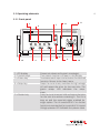
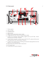
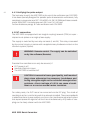
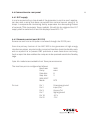
1
NSG 3025
Burst generator
User manual
601-210D
NSG 3025
Burst generator
User Manual
NSG 3025 Burst Generator
Contents
1
Safety advice
1.1General
1.2
Installation guidlines
1.3
Test execution
1.4
Dangers concerning the generator
1.5
Dangers concerning the EUT
1.6
Applicable safety standards
2
Unpacking, storage and transport
2.1General
2.2
Storage and transport
2.3Unpacking
3
Description of the instrument
3.1Introduction
3.2
Operating elements
3.2.1 Front panel
3.2.2 Rear panel
4
Installation and power supply
4.1Installation
4.2Location
4.3
Power supply
4.3.1 Instrument power supply
4.3.2 EUT power supply
4.4
Front panel connections
4.4.1 Coupling via the pulse output
4.4.2 Coupling clamp
4.4.3 Verifying the pulse output
4.5
EUT connection
4.6
Connections to rear panel
7
7
8
9
10
10
11
12
12
12
13
14
14
15
15
17
18
18
18
19
19
20
21
21
21
22
22
23
4.6.1 EUT supply
4.6.2 Remote control port (RS 232)
4.6.3 Control input for external CDN
4.6.4 Interlock (Optional)
4.6.5 Trigger input and output
4.6.6 EUT FAIL input
4.7Mounting
5
Block diagram
5.1
HV circuit and HV pulse generator
5.2
Coupling network
6Operating
6.1
Local operation
6.2
Operating states
6.3
Main menu
6.4
Options menu
6.5
Ramping menu
6.6
About menu
6.7
Validity range of parameter setting
6.8
System messages
7
Function check
7.1Controls
7.2
Pulse generator
7.3
Remote control
7.4
Mains coupling
7.5Faults
7.6
Trouble shooting
8Standards
8.1
Safety measures as per VDE 0104
8.2
Typical applications and standards
8.3
Pulse verification with CAS 3025
9Maintenance
9.1Service
9.2
External care
10
Replacement parts
11Disposal
12
Technical data
12.1 Electrical specifications
23
23
24
27
31
31
32
34
34
35
36
36
38
39
40
42
45
46
46
48
48
49
49
49
50
51
53
53
54
56
57
57
58
59
60
61
61
12.2Dimensions
12.3 Environmental conditions
13
Ordering information
13.1Options
14
Definitions
14.1Abbreviations
14.2Standards
15Addresses
64
64
65
65
66
66
67
68
5
1 Safety Advice
The generator and its accessories work at high voltage.
Improper or careless handling can be fatal!
These operating instructions form an integral part of the equipment and must
be available to the operating personnel at all times. All the safety instructions
and advice notes are to be observed.
Neither Teseq AG nor any of the subsidiary sales organisations can accept any
responsibility for personal, material or consequential injury, loss or damage that
may result from improper use of the equipment or accessories.
1.1 General
Use of the generator is restricted to authorised and trained specialists.
The generator is to be used only for the purposes set down by the manufacturer.
The construction of the unit renders it unsuitable for use in an explosive atmosphere.
Persons fitted with a heart pacemaker must not operate the instrument nor
approach the test rig while it is in operation.
7
8
Only approved accessory items, connectors, adapters, etc. are to be used to
ensure safe operation.
Advisory measures are described in these instructions as follows:
WARNING: For potential dangers that could result in
serious injury or death.
CAUTION: For potential dangers or mishandling that
could cause light injuries or material damage.
1.2 Installation guidelines
The instrument conforms to protection class 1, but with an increased leakage
current.
Local installation regulations must be respected to ensure safe flow of leakage
currents.
Operation without a protective earth connection is forbidden!
Two independent protective earth connections are necessary (instrument and
EUT* supply) connected back to the local permanent installation or to a fixed,
permanent protective earth conductor.
Operate the equipment only in dry surroundings. Any condensation that occurs
must be allowed to evaporate before putting the equipment into operation. Do
not exceed the permissible ambient temperature, humidity or altitude.
Use only legally approved connectors and accessory items.
Ensure that a reliable return path for the interference current is provided
between the EUT and the generator. The reference ground plane and the earth
connections to the instruments as described in the relevant test standard serve
this purpose well.
*) Explanation see chapter «Definitions»
NSG 3025 Burst Generator
The instruments must generally not be opened. This may only be undertaken
by a qualified specialist whereby any precaution measures as per this manual
are to be observed. Since the equipment generally works with two independent
power supplies for the generator and the EUT, the instrument must first be
disconnected from both sources before any changes in the test set-up are
made. Besides the mains supply itself, certain instruments or parts thereof,
also operate at high voltages which are not provided with any internal form of
extra protection against being touched.
1.3 Test execution
The test area must be so organised that no unauthorised persons have access
during execution of a test. If the safety contact (optional interlock) is used as a
means of access control to the test zone (e.g. Faraday cage), then an additional
contact in series is necessary to provide protection for parts of the EUT that
are in danger of being touched.
EUTs, together with their accessories and cables, are to be considered as being
live during a test. The test generator must be stopped and the EUT supply interrupted before any work is carried out on the EUT. This can be implemented by
opening the interlock circuit, but depends on the type of generator in use.
The EUT is to be tested only in a protective cage or under a hood which provides
protection against electric shock and all manner of other dangers pertaining to
the particular EUT (see Dangers concerning the EUT).
The safety instructions concerning all the instruments and associated equipment involved in the test rig are to be observed.
The configuration of the test rig is to be strictly in compliance with the methods
described in the relevant standard to ensure that the test is executed in a
standard-conform manner.
9
10
1.4 Dangers concerning the generator
Local burning, arcing, ignition of explosive gases.
Danger from the resultant EUT supply current caused by a flashover or
breakdown resulting from the superimposed high voltage effects.
Disturbance of unrelated electronics, telecommunications, navigational
systems and heart pacemakers through unnoticed radiation of high frequency energy.
In most test rigs the interference voltage is superimposed also on the protective earth conductor of the EUT in accordance with the requirements of the
test standard. Earth contacts or pins (e.g. in German and French connectors)
as well as the EUT earth itself can hence be at a dangerous to touch voltage.
The screws, too, in certain connectors are linked to the protective earth.
1.5 Dangers concerning the EUT
EUTs are often simply functional samples that have not previously been subjected to any safety tests. It might therefore happen that the EUT could get
damaged by internal overloads caused by disturbed control electronics or it
may even start to burn.
As soon as the EUT shows signs of being disrupted the test should be stopped
and the power to the EUT switched off.
Internal disruption of the electronics can result in the interference voltage
or the EUT supply voltage being present on the EUTs housing.
Electrical breakdown or arcing from and in plugged connections that are
overstressed voltagewise during the test.
NSG 3025 Burst Generator
Explosion of electronic components with fire or fragmentation as a result of
the energy dissipated, e.g. from the resultant supply current or ignition of
vaporised plastics materials.
Faulty behaviour by the EUT, e.g. robot device strikes out, temperature controller fails, etc.
1.6 Applicable safety standards
Development and manufacture is in compliance with ISO 9001.
The equipment conforms to the safety requirements of IEC 1010-1 / EN 61010-1
(Safety requirements for electrical equipment for measurement, control and
laboratory use). The switching power supply conforms to IEC 950.
All mains driven types of generators are equipped for high voltage working
safety in accordance with VDE 0104. Details see chapter «Standards».
The interference immunity has been tested in conformity with EN 50 082-1.
It is the user›s responsibility to ensure that the test set up does not emit excessive radiation that might affect other equipment.
The generator itself does not produce excessive radiation, however applying
burst-pulses to an EUT may cause EUTs and its cables to start radiating EMI.
The method recommended by standardisation bodies to prevent unwanted
emission is to operate the test rig in a Faraday cage.
11
12
2Unpacking, storage and
transport
2.1 General
Do not throw anything away!
Packaging either: Keep for despatching the instrument to the calibration service
Return to the relevant sales outlet
Dispose of in an environmentally friendly manner, thus:
Packaging materials:
Card box:
cardboard
Padding:
CFC-free polystyrene foam
Plastic bags: polyethylene
If large temperature difference has been experienced, allow some hours to elapse
to permit the temperature to stabilise before opening the package. Avoid the possibility of condensation occurring!
2.2 Storage and transport
Do not stack, neither packaged nor out of the packing.
Do not put upside down, arrows on the packaging must always point
upwards.
Protect from dampness, heat, cold and rain.
Do not throw.
Do not put anything on the instrument or on the packaging-respectively.
Despatch only in the original packaging or its equivalent.
NSG 3025 Burst Generator
2.3 Unpacking
Is the packaging intact?
If NO
g complain to transportation company
Are all the packages present and correct?
If NO
g complain to transportation company
Open the packaging, remove the accessories.
Lift the instrument out of the packaging.
Are the instrument and the accessories intact?
If NO
g complain to transportation company
Are the contents of the package complete according to the picking list?
If NO
g complain to sales outlet
Keep the operating instructions with the instrument. (Copies can be ordered
from the sales outlet)
Save the packaging. (Inform the sales outlet in advance if you intend to return
the package material.)
ATTENTION: An electrical function check is only permissible and possible by a trained specialist.
13
14
3 description of the instrument
3.1 Introduction
This top class EMC test instrument for burst or electrical fast transient tests
provides an efficient means to perform functional examinations on all types
of electronic equipment to determine their susceptibility to electromagnetic
disturbances.
The disturbance generator comes with a built-in 1-phase coupler (CDN) for
max. 16 A. Optional CDNs for EUTs up to 100 A/phase and coupling clamps
are available.
The NSG 3025 is the best choice for executing interference immunity tests with
burst pulses called for in IEC/EN 61000-4-4 and by related product standards.
Thanks to special flexibility with regard to parameter setting the generator is also
most suitable for complex applications in the field of research and development.
Besides, its easy handling facilitates mobile use for tests on large machinery
and installations on site.
The instrument generates bursts of interference pulses simulating those produced by inductively loaded switches. Such pulses, with their very fast rise
times, have a spectrum that extends to over 300 MHz. It may occur where
currents are switched by means of electromechanical devices, e.g. with motors,
circuit breakers and relays, fluorescent lamps, etc. – Burst tests are hence
demanded by practically all the relevant standards for the testing of electronic
equipment in addition to testing with electrostatic discharges using an ESD
simulator such as e.g. a model NSG 435.
§
Before you can sign your electronic products with the legally required CE
symbol within the EC you must have performed an EMC test in conformity with EN/IEC 61000-6-1 and -2 or equivalent product standards.
NSG 3025 Burst Generator
3.2 Operating elements
15
3.2.1 Front panel
1
2
8
11
7
FAST TRANSIENT BURST GENERATOR
NSG 3025
3
12
4
6
5
9
10
1. LCD display
Shows set values and system messages.
2. Function keys
Their active function is shown in the display.
3. «Enter» key
Terminates each input and activates the selected
function. Return to the basic menu.
4. «Stop» key
Stops the current test, switches the high voltage
off and resets the timer for the test time. The
green «stop» LED indicates the ‹stop›
state.
5. «Pause» key
Puts the current test on hold and stops the timer
for the test time without resetting it. The HV is
kept on and the external trigger enabled for
single spikes. The HV switches off if no further
function is executed within a period of 2 minutes.
Orange «pause» LED indicates the ‹pause› state.
16
6. «Run» key
7. «Up/down» key
8. HV socket
9. Earth connection
10. EUT connection
11. LED «pulse»
12. Handle
Switches the high voltage on and, once the set
level has been attained, starts the test running
for the duration defined by the «Test time» timer.
Red «Run» LED indicates the ‹run› state.
To alter the selected parameter.
HV-OUT for direct pulse output to a coupling
device and for calibration of the pulse characteristics.
Return path from the ground reference plane.
With decoupling from the EUT power source. PE
is connected to ground by an inductor.
The LED flashes for each generated pulse.
Adjustable handle
NSG 3025 Burst Generator
3.2.2 Rear panel
17
2
10
6
8
11
7
5
CAUTION
To prevent electric shock
connect the protective Earth
conductor of the mains cable
and the EUT supply to a solid
Earth. Remove the mains cable
before exchanging a fuse. Replace
fuse only with the Specified type and rating.
EUT AC INPUT
200 VAC Max. / 1GA Max.
SWITCHED
POWER
CAUTION
A test rig incorporating this instrument can
radiate strong electromagnetic interference.
Operation only permissidle in a closed faraday cage.
WARNING
Lethal danger trough high voltage
do not oplin singl there are no userserviceable parts inside.
Service work to be carried out only
servie workt to be Carried out Only
by afactorytrained specialist.
12
1.
2.
3.
4.
5.
6.
7.
3
9
4
1
Cable support
Fan, air outlet
Ventilation slots
Mains switch
Mains input for generator power supply
Voltage selector with fuse for the generator supply
D-sub 9-pin connector with auxiliary signals such as EUT-FAIL, PULSE
TRIGGER and EXTERNAL TRIGGER
8. D-sub 25-pin connector, remote control RS 232, DCE, without HW control
lines 9600 baud, 8-bit, even parity, 2 stop bit
9. D-sub 37-pin connector for controlling an external coupling device such as
CDN 131-151 or CDN 133-153
10.Earth screw, for protective earth connection
11. EUT supply input
12.Connectors for interlock (Option)
18
4Installation and power supply
4.1 Installation
Apart from the power connections, no further installation is necessary for
manual operation of the instrument.
The test rig itself must, however, be configured precisely in accordance with
the relevant standard and test plan to enable standard-conform burst tests
to be carried out. An earth reference plane of at least 1 m² is necessary while
observing a minimum spacing from nearby walls of 0.5 m.
4.2 Location
A screened room (Faraday cage) is the only location that should be considered
for running the generator.
Only trained, authorised personnel without a heart pacemaker should be granted
access. The ambient conditions should be within the specifications of all the
equipment involved.
An environment as per IEC 68-1-(1988) is recommended:
Ambient temperature: 15°C
to
35°C
Relative humidity:
25%
to
75%
Air pressure:
86 kPa to
106 kPa
The ventilation slots on the instrument must not be blocked.
The free space available should be large enough so that a tidy, standard-conform
test rig can be arranged for all the expected types of EUTs, thereby providing at
least 0.5m distance from any walls.
NSG 3025 Burst Generator
4.3 Power supply
The NSG 3025 has two independent power supply inputs:
(1) Instrument supply via an IEC 320/IV equipment connector
(2) EUT supply via an IEC 320/IV equipment connector (250 V/16 A)
WARNING: The EUT supply produces earth leakage
currents of up to 5 mA with 50/60 Hz supplies and up
to about 15 mA with 400 Hz/120 V supply because of
the coupling capacitors and filter (CDN) involved. The
NSG 3025 must hence be efficiently earthed.
One of the following additional protective measures might be necessary,
depending on local regulations:
Permanently connected additional earth conductor.
Both power feeds as well as the earth lines to be connected separately to
the building’s fixed installation.
CAUTION: RCD circuit breakers can be triggered by the
EUT supply. This may happen while the instrument and/
or the EUT is in operation.
4.3.1 Instrument power supply
The device can be connected to a 100, 115, 220, 230 or 240 Volt, 50/60 Hz mains
outlet. The voltage selector is to be set to suit the local conditions (for 100/115
V set to 115 V and for 220–240 V set to 230 V).
Permissible mains voltage tolerances:
100 and 220 V
-10% +15%
115 and 230 V
± 10%
240 V+6% -15%
It is imperative that a protective earth connection is also provided.
19
20
4.3.2 EUT power supply
CAUTION: A suitable fuse must be provided separately in
the external installation. Maximum permissible nominal
rating for the fuse, according to the CDN specification:
250 V/16 A slow (50/60 Hz) for DC applications. Special
fuses required.
We recommend a permanent connection to a junction box with a fuse. This box
can also provide a protective earth connection for the reference ground plane
as well as outlet sockets for the instrument supply (1) and further equipment.
CAUTION: Electronic components, frequency inverters
and dc power supply units can be disrupted or damaged
by the feedback effects of the burst signal.
The link between the protective earth connection and a protective earth conductor is to be established before any other connections are made.
Rear panel: EUT Input
(male)
N
L
PE
NSG 3025 Burst Generator
Front panel: EUT Output
(female)
N
L
PE
4.4 Front panel connections
4.4.1 Coupling via the pulse output
CAUTION: Use only accessories which are designed for
burst pulses up to 4.8 kV.
Do not set the burst voltage higher than the breakdown voltage rating of the
connected parts.
4.4.2 Coupling clamp
If the burst interference is to be injected into signal lines by means of a
capacitive coupling clamp same is to be plugged into the «pulse output» of the
NSG 3025.
The coupling clamp type CDN 8014, which is available as an accessory, is constructed in conformity with the requirements of IEC 61000-4-4. The CDN 8015 is
equipped with an interlock switch for additional touch prevention which forces
the NSG 3025 into the «stop» state if the clamp is opened.
Select «EXT» in the coupling menu to feed the burst pulses to the coupling
clamp. This automatically de-selects any other line coupling.
NOTE: Teseq recommends powering the EUT through the
integral CDN even when working with a coupling clamp.
The EUT power supply is thereby still fed through the
decoupling circuit and is hence connected to a reproducible source impedance. Any tendency for interference
currents to creep back to the mains supply will be prevented by the mains filter in the CDN.
21
22
4.4.3 Verifying the pulse output
The best way to verify the NSG 3025 is the use of the verification set CAS 3025.
It has been specially designed for periodic pulse characteristic verifications, fully
compliant to requirements of IEC / EN 61000-4-4: Ed 2.0 (2004) and latest amendments 2006/2007. It Includes one each 50 Ω and 1 kΩ HV load.
Further details see paragr. 8: Pulse verification with CAS 3025.
4.5 EUT connection
The NSG 3025 is equipped with an integral coupling network (CDN) to super –
impose burst spikes on a single phase supply.
The supply is switched by two relay contacts (L and N). This relay is actuated
by the control circuitry in series with a supplementary hardware contact on the
interlock system (Option).
WARNING: Remote control: The supply can be switched
on by the software (Remote).
Potential-free conditions can only be assured, if:
EUT power is off
Interlock (Option) is open
The NSG 3025 is switched off
CAUTION: It is essential to use good quality, well mounted
plugs since otherwise the necessary breakdown and
arcing strengths might not be achieved amongst other
problems. A burst voltage of 4.8 kV can cause a breakdown or arc across normal mains insulation.
For safety tests, the EUT has to be connected via the IEC plug. The mode of
coupling must be in conformity with the relevant standard. There are standards
in existence that only ever subject one line to the interference signal and others
that superimpose the signal on all the lines simultaneously. Any mode of coupling can be freely chosen with the NSG 3025.
NSG 3025 Burst Generator
4.6 Connections to rear panel
23
4.6.1 EUT supply
It is to be protected by a fuse ahead of the generator to suit the user’s application but with a rating that does not exceed the nominal current rating of 16
Amps. A temperature monitoring facility supervises the decoupling chokes
of external CDNs (automatic Teseq models). Should this be triggered the EUT
supply shall be switched off and the display shows INFO 114.
4.6.2 Remote control port (RS 232)
Remote control from a computer is achieved through the RS 232 port.
Since the primary function of the NSG 3025 is the generation of high energy
interference pulses, any electrically connected interface should preferably work
with an optical link to prevent EMC problems or even destruction occurring.
Such an opto-link also enables the computer to be operated outside the Faraday
cage.
Opto-link modules are available from Teseq as accessories.
The interface port is configured as follows:
Baud rate:
9600
Parity:even
Data-bits:8
Stop-bits:2
XON/XOFF
Mode:DCE
Pin-out:
Pin 1
Pin 2
Pin 3
Pin 7
Pin 18
Pin 25
Protective ground
Input (Rx)
Output (Tx)
Signal ground
+12 V
-12 V
24
Remote control
A number of control software possibilities may be considered:
1 Teseq program WIN 3025:
This is a complete, comprehensive, «ready-to-work» Windows based
package which offers the possibility to store whole control sequences,
ramping functions and result logging.
2 Application with standard programming environments for measuring instruments:
Programming environments that may be considered are VEE TM from hp as
well as LabWindowsTM from National Instruments.
4.6.3 Control input for external CDN
The 37-pin sub-D socket contains all the necessary signals which are needed
to control an external CDN.
For burst tests in combination with surge and/or higher EUT currents (1-ph/3-ph)
Teseq offers coupler models CDN 131/151 (1x 25 A), CDN 133/153 (3x 25 A) or
CDN 163 (3x 100 A). For automatic CDNs a system interlock option INA 3025
and adapter INA 3026 are provided.
Connections and pin configuration (37-way):
Outputs:
Signal type:
Inputs:
Following outputs are available
K0-K4
for selection of the required coupling mode
EUT_POW for controlling the power switch of the EUT supply
WL_GRN
equipment ready (software signal)
TTL/CMOS compatible
Active = high = 5 V
Internal impedance 1 kΩ
Following inputs are available:
CDN temperature control (supervision of limiting value)
CDN single phase
External limitation of burst voltage setting range
NSG 3025 Burst Generator
Pin
Signal
Description
1
NC
–
2
GND
Connection to ground via choke
3
EUT_POW
Sets EUT power on/off
4
K4
Coupling to PE, external CDN
5
K3
Coupling to L1, external CDN
6
K2
Coupling to N, external CDN
7
K1
Coupling to L2, external CDN
8
K0
Coupling to L3, external CDN
9
WL_GRN
Sets warning lamps green/red
10 to 15
16
NC
V1PH
–
External CDN: Selection of phases
17
25
High (5 V) = PE, N, L1
V3KV
Low (0 V) = PE, N, L1, L2, L3
External CDN: Voltage limitation (see pin 35)
TEMP
Low (0 V) = inactive
External CDN: Temp. overload
High (5 V) = active
18
High (5 V) = active
19
20
GND
NC
Low (0 V) = inactive
Connection to ground via choke
–
21
GND
Connection to ground via choke
22 to 34
35
NC
V2KV
–
External CDN: Voltage limitation (see pin 17)
36
NC
–
37
GND
Connection to ground via choke
High (5V) = active
Low (0V) = inactive
26
Pin assignment
19
1
37
20
The input that results in the most sever limitation on the operation of the instrument, whether internal or external, always carries the highest priority.
The CDN overheat input will prevent the EUT supply being switched on and shall
be indicated by a system message.
Activating the V1PH input (+5 V) has the effect of excluding the setting possibilities for L2 and L3 (for external 1-phase CDN).
The maximum possible setting for the burst voltage can be reduced to 2 kV or 3
kV resp. by means of the voltage limitation facility inputs V2KV and V3KV (activation with +5 V). The voltage limitation facility is used for connection systems
whose insulation is not suitable for the full burst voltage. The inputs can also
be used as an external limiting device to protect the EUT.
The following table shows the possible stages of voltage limitation:
Maximum voltage
Voltage
Voltage
4800 V
limitation 2
0
limitation 3
0
4500 V
0
1
1500 V
1
0
500 V
1
1
0 = Low = 0 V, 1 = High = 5 V
NSG 3025 Burst Generator
4.6.4 Interlock (Optional)
The NSG 3025 has an integral Interlock system in keeping with the kind of safety
standard expected of a high voltage test instrument. If there is no Interlock
installed, it is possible to up-grade the unit by your sales office.
This system has the following functions:
1 Input for external monitoring, e.g. from special coupling networks and
access control restrictions.
2 Emergency off switch opens the Interlock circuit (High voltage and EUT
power).
3 Operating mode: The NSG 3025 cannot be switched to «run» or «pause»
if the Interlock circuit is not closed. The «stop» function is activated if the
Interlock circuit is opened while the generator is in the RUN state.
4 EUT-Power: The EUT power supply cannot be switched on if the interlock
circuit is not closed. The EUT supply is switched off if the interlock circuit is
opened while the supply is switched on.
5 Warning lamps: The green lamp is switched off and the red one on when
the interlock circuit is closed.
6 Display: An open interlock circuit is shown on the display by an open switch
symbol.
7 Status messages to the remote control computer.
8 Interlock output for other system equipment.
The interlock system for all the equipment in the ProfLine range has the same
configuration and hence numerous items can be successfully connected
together.
27
28
Each instrument is equipped with two 15-pin connectors which serve as the
Interlock input and output respectively. The Interlock circuit must always be
terminated at both ends with the relevant conductors being looped through
the various safety contacts in the system. This is achieved automatically when
using original Teseq accessories by making the connections to the Interlock
connectors with 15-way standard cables wired on a 1:1 basis.
An arbitrary number of instruments and/or accessory devices can be incorporated in the safety concept. The high voltage and the EUT supply are only
enabled if the safety conditions are fulfilled at every unit that is connected
(emergency stop button unlocked, safety circuit closed, etc.)
The interlock function must be implemented for the control of warning lamps
to comply with VDE 0104. Once the Interlock circuit is closed, the instruments
are able to be switched on and the red lamp lights up.
If an instrument is to be used without an external interlock contact then the
two terminating connectors supplied must be inserted.
Signal levels:
Voltage
48 VDC max.
Current 20 mA min. /1 A max.
Connector:
15-pin sub-D socket
Max. permissible cable length:
3 m each, screened
(safe operation is guaranteed up to 10 m)
Actuation is via potential-free switch contacts.
All signals are active LOW, i.e. switched to GND.
The pin-out at the interlock input and output connectors are identical. All the
pins are individually interlinked whereby the internal connection between the
two pins nr. 3 shall be interrupted by the emergency stop button or by the
internal interlock facility when either one is activated.
NSG 3025 Burst Generator
PinFunction
1
GND, 0V
2
NC, linked to the other interlock connector
3
Interlock input/output (internal switch)
4
NC, linked to the other interlock connector
5
Interlock status (triggers the interlock function in the
instrument and switches the relay if + 12 V to + 48 V
6 to 8 NC,
linked to the other interlock connector
9
Switches warning lamps and peripherals active as
soon as the NSG 3025 is switched from standby to
ON)
10 to 15
NC, linked to the other interlock connector
Housing
Screen connected to ground
8
15-pin connector
1
15
9
NSG 3025
Termination 1
1
1
Termination 2
1
1
15
15
15
15
Rear view
Circuit diagram of the interlock system
S: External safety switch (e.g. test hood, door-switch, emergency button, etc.)
29
30
The safety contacts must be connected in series when several access safety
barriers are necessary. An open contact or an input raised to more than 1.5 V
is enough to inhibit the instrument.
in 1
GND
out
9
1
WL SELECT
INT S1
INT S1
INT S2
INT RESET
15
8
15
8
EUT
power relay
EUT
Power
on
HV
on
supply
Emergency off
Interlock relay
Internal circuit diagram of the interlock
NSG 3025 Burst Generator
µP
recognition
4.6.5 Trigger input and output
Trigger input:
The EXT TRIGGER input is only active when the instrument is in the PAUSE
mode. The external trigger signal causes a burst package to be generated. The
specification of the package are given in the display.
Applications by user control:
Special modulation of pulse packages
Synchronisation of pulse packages by an external signal
Simulation of noise by pulse modulated transmitters (digital phone)
The minimum repetition rate is monitored from the controller.
Trigger output:
The TRIGGER OUTPUT signal serves to synchronise an oscilloscope.
4.6.6 EUT FAIL input
The EUT-Fail Input signal serves to enable integrity monitoring of the device
under test.
The generator is set to the «stop» state when this input is activated and the
system message «INFO 115» is displayed. The high voltage supply and the
EUT Power will be switched off.
The circuitry for recognising faulty EUT operation is dependent on the type of
EUT involved in each case and is generally different for every test. A disturbancefree connection to the system must be provided.
Signal type:
TTL/CMOS compatible
Active = high = 5 V
Internal impedance 1 kΩ
31
32
Pin
Signal
Description
1
EUT_FAIL
Input: Stops the NSG 3025 and switches the EUT off
2
EXT_TRIG
3
GND
–
4
GND
Connected to GND via choke
5
GND
Connected to GND via choke
6
NC
–
7
P_TRIGGER
Output: Trigger for external equipment (CRO)
8
NC
–
9
NC
–
Input: For external trigger signal. Generates 1 pulse
package per edge (switch against GND, internal impedance 10 KΩ)
1
5
Connector pin-out
9
6
4.7 Mounting
1 EUT power connection: The mains cable for the EUT power connection is
plugged and easily exchangeable. This is the safest method of connection.
2 HV capacitor: The power demanded by a 4.8 kV / 1 MHz spike sequence is
delivered from the high voltage module via a large storage capacitor so that
the whole pulse package remains within tolerances.
3 HV supply: A 50/60 Hz transformer with voltage switching on the primary
side generates the supply voltage for the fly back converter which produces
the high voltage.
NSG 3025 Burst Generator
33
4 Power unit: The supply to the instrument’s electronics is provided by a
switch mode power supply unit having an input voltage range from 85 V to
264 V. The power unit complies with the requirements of IEC 950.
5 UP/DOWN key: Permitting a simple, quick and quasi analogue setting of
the test data. Most of the parameters can be continuously altered during
operation as though by a potentiometer.
6 µP-control: The heart of the control circuitry is a state of the art, efficient
16-bit microprocessor in SMD technology.
7 A large, graphical LCD display panel with back-up illumination, shows the
currently set values and enables local operation to be carried out rapidly
and simply.
8 The small optimised EMC casing allows easy testing for both mobile use or
in laboratory.
34
5block diagram
Mains power
Fuse
Rectifier
Thermo
switch
HV-Supply
HV-SWITCH
Coupling / Decoupling network
INTERLOCK
(Option)
REMOTE
PULSE
OUTPUT
CONTROLLER
EXT. CDN
EUT
OUTPUT
EUT
INPUT
USER
Front panel
5.1 HV circuit and HV pulse generator
S1
T1
D1
Z1
S3
Z4
S4
To
+/-
Interlock
C1
HV-Control
NSG 3025 Burst Generator
S2
C2
Z3
CDN
5.2 Coupling network
35
L
L
PE
PE
2 x C4
N
EUT
Input
N
4 x C3
3 x L1
EUT
Output
S6
Pulse
Output
INTERLOCK
Controller
From pulse generator
Legend to diagrams 5.1 and 5.2
T1
D1
C1
C2
C3
C4
S1
S2
S3
S4
S5 S6
Z1 Z2
Z3
L1
HV transformer
HV rectifier
HV energy storage
Spike storage capacitor
Coupling capacitor 10nF
Reverse filter
Interlock relay
Safety discharge switch
Fast solid state switch
Polarity changeover switch
Coupling relays, individually controllable
EUT supply circuit relay
Decoupling impedance
Impedance for pulse width stabilisation
Source impedance
Decoupling chokes
The CDN permits unsymmetric (single conductor) and asymmetric (all conductors
together) coupling.
36
6Operating
6.1 Local operation
This chapter presents an introduction into the multitude of possibilities that can
be achieved with the NSG 3025.
How to change parameters:
Select the parameter by means of the soft-keys. The menu changes to the
ramping menu. The value in the display will be shown in inverse mode. Change
the value with the PULL UP / DOWN keys and confirm with ENTER. The value
will show up normally and the menu changes back to the option menu. See
also following diagram.
If there is no confirmation, the original value shall be shown again and a message
will be displayed.
NSG 3025 Burst Generator
37
38
6.2 Operating states
The instrument can be switched into the following states:
STOP
Interlock closed:
The instrument is active, the display is in operation. The EUT
supply can be switched on, all settings are possible. The HV
is switched off. With «run» or «pause» the HV is switched on.
The green LED nearby the STOP key is alight.
Interlock open:
High voltage and EUT power out are safely inhibited. It is not
possible to switch on the EUT power or the High voltage.
PAUSE
High voltage is switched on, the instrument is waiting for
external trigger pulse, the test time runs. This operating state
is cancelled after 2 minutes (provided there was no triggering
meanwhile), and the instrument goes into the «stop» state.
The test time is reset to zero.
RUN
The instrument triggers burst pulses automatically according
the parametter settings. The instrument switches itself into
the «stop» state at the expiration of the test time.
NSG 3025 Burst Generator
6.3 Main menu
This menu is normally displayed and gives an overview of all parameters within
the chosen fix setting «LEVEL» XY or in the «USER» program 1 to 99.
LEVEL:
Selects a test set-up. The Level definitions are according to IEC
61000-4-4 (P = Positive, N = Negative, A = Alternating). Only the
PHASE and the coupling paths are changeable.
LEVEL 1:
LEVEL 2:
LEVEL 3:
LEVEL 4:
USER:
The USER settings are freely definable set-ups. All parameters
(including rampings) of the generator will be stored. Ramping
functions are only available in the USER set-ups.
COUPLING:
Selects the coupling path. INTernal means coupling the pulses
to the internal CDN. EXTernal goes to the PULSE OUTPUT. If
SEQuence is selected, the pulses will be coupled to each path
for the selected test time.
500 V, 5 KHz, 300 ms, 75 Spikes
1000 V, 5 KHz, 300 ms, 75 Spikes
2000 V, 5 KHz, 300 ms, 75 Spikes
4000 V, 5 KHz, 300 ms, 75 Spikes
39
40
EUT P:
Sets the EUT POWER on / off.
Attention: If Interlock is open, it is not possible to switch the
EUT POWER on!
TIMER:
Sets the test time. The generator stops when the test time
has elapsed. In the Sequence mode the total test time is
calculated thus:
Coupling: INT SEQ L1, N, PE => Test time x 3
OPTIONS:
Change to the Options menu.
6.4 Options menu
In such a USER menu the parameters of the pulse generator can be modified.
All parameters (without rampings) can also be changed during «run» or «pause».
Change to the «main» menu with «enter».
VOLTAGE:
New setting of the pulse voltage amplitude. The polarity is
selectable by a separate soft-key. If ALTernate is selected,
the pulses are positive and then negative each for half of the
test time.
FREQ:
New setting of the burst frequency.
NSG 3025 Burst Generator
PHASE:
New setting of the phase angle. An EUT AC supply is necessary (EUT POWER on) for synchronous triggering. Synchronous triggering means:
Burst package
V
EUT Mains
t
PHASE
PHASE
REP
REP:
New setting of the repetition time. The repetition time is
defined from the first pulse of a package to the first pulse
of the following one. If the duration time of the package is
equal or higher than the repetition, continuous operation will
occur.
SPIKES:
New setting of the number of spikes. The number of spikes
also defines the duration time of a package:
tDURATION = SPIKE x
1
FREQUENCY
41
42
6.5 Ramping menu
Different rampings are selectable for various parameters. Differing against controls by a PC (WIN 3025) during manual operation one value only can be ramped
at time. Upon selecting a parameter, the following display will be presented:
ABOUT:
Change to the menu ABOUT.
START: New setting of the START value. Only shown if a FUNCTION
is selected.
STOP: New setting of the STOP value. Only shown if a FUNCTION is
selected.
STEP: New setting of the STEP value. Only selectable if the function
LINEAR is active.
FUNCTION:
Defines the mode for the ramping.
Remarks: Only positive voltage ramping (START < STOP) is allowed.
The TEST TIME will be rounded to a valid value. (It depends
on the repetition time and the event times).
Calculated step sizes will be rounded to the next possible
value.
NSG 3025 Burst Generator
LINEAR: The values change from START to STOP linearly with STEP
increments. The STEP value will be shown after FUNCTION
has been selected. The duration time for each step and the
number of steps will be calculated automatically:
Number of steps = (Range / Step size) + 1
Step duration = Test time / Number of steps
Example : Start 10 kHz, Stop 100 kHz, Step 10 kHz, Test time 500 sec.
Every 50 seconds the frequency increments by 10kHz. 10
steps will be executed.
10 kHz
30 kHz
50 kHz
70 kHz
90 kHz
50 sec 20 kHz
40 kHz
60 kHz
80 kHz
100 kHz
Test time 500 sec
NUMBER: Example : The values change from START to STOP linearly with a fixed
number of steps. The NUMBER soft-key will be shown after
FUNCTION has been selected. The duration time for each
step and also the step size will be calculated automatically:
Step duration = Test time / Number of steps
Step size = Range / (Number of steps -1)
Start 280 V, Stop 1000 V, Number 10, Test time 200 sec. Every
20 seconds the voltage increments by 80V. 10 Steps will be
executed.
1 kV
920 V
840 V
760 V
680 V
600 V
520 V
Test time 200 sec
440 V
360 V
280 V
43
Hz
6k
23
Hz
21
4k
Hz
19
5k
z
kH
17
7
Hz
16
1k
z
kH
14
6
kH
13
3
12
1k
kH
11
0k
z
Start 100 kHz, Stop 236 kHz, Percent 10, Test time 600 sec.
Every 60 seconds the repetition increments by 10%. 10 Steps
will be executed.
Hz
Example : z
The values shall change from START to STOP as percentage of
the previous value. The PERCENT soft-key will be shown after
FUNCTION has been selected. The duration time for each
step and also the step size will be calculated automatically:
Hz
PERCENT: 10
0
44
Test time 600 sec
CONTINUOUS: Only used for FREQUENCY changes. It is possible to set a
permanent frequency with this function. The parameter tREP
is set to off.
Test time
NSG 3025 Burst Generator
STATIC:
Sets the ramping function to off. The set-up before selecting
the ramping function will be restored.
STATISTIC:
Only used for FREQUENCY changes. In the range START to
STOP the burst frequency will change randomly during the
test time. Frequencies higher 25 kHz will be set per packet,
frequencies below within the packets. The number of spikes
will be constant.
6.6 About menu
This menu shows the firmware versions.
PRINT:
Prints one complete set-up of the generator (1 page) via the
serial port. Standard ASCII format.
LANGUAGE:
Sets the language for the messages on the display and the
printer.
45
46
6.7 Validity range of paramter setting
Parameter setting range
Minimum
Maximum
Step size
Spike idle voltage (Volts)
200 V
4800 V
10 V
-200 V
-4800 V
Burst frequency
0,1 kHz
1 MHz
0.1 / 1 kHz
Continuous frequency
0,1 kHz
10 kHz
0.1 kHz
Burst repetition time
20 ms
99999 ms
1 ms
Spikes per burst
1
255
1
Test time
1s
99999 s
1s
Synchronisation (Phase)
0°
359° / async.
1°
Coupling internal
L1, N, PE
Coupling external
L1, L2, L3, N, PE
If mutually excluding values are selected, the latest input setting is accepted
and the contradictory parameter(s) are set to permissible values. A beep warns
the user. The automatically adjusted value(s) blinks briefly.
The duration of a burst is given by the quotient of =
Number of spikes
Burst frequency
Direct setting of the burst duration is not practical in view of the possible range
from 1µs up to infinitive.
6.8 System messages
All the messages from the system are indicated on the display panel by means
of a code number.
NSG 3025 Burst Generator
Info number
006
008
103
104
105
106
115
121
122
125
126
127
129
140
141
142
143
145
146
147
148
149
150
151
152
153
154
155
208
210
211
212
213
Status messages
During RUN/PAUSE interlock opens or
RUN/PAUSE key pressed with interlock open
Fault in high voltage generator
Fault in the +12 V supply
Fault in the -12 V supply
Fault in the +5 V supply
Setting of «Phase 0...360°» without synchronisation signal
(phase L1 missing or on DC voltage)
EUT failure (EUT-Fail)
Pulse voltage setting too high
Repetition setting too short
Time-out HV Supply
Permanent burst generation not possible
HV switch failure
Selected value(s) not confirmed
Polarity selection not valid
Linear not valid
Number not valid
Percent not valid
Percent not valid
Number not valid
Percent not valid
Number not valid
Percent not valid
Number not valid
Percent not valid
Test time not valid
Voltage was adjusted
Ramping was changed
No ramping possible with ext. trigger
CDN was changed
External trigger missing
Device fault was detected
External OK signal failure
Temperature fault
47
48
7 function check
Many functions are checked automatically by the control module upon powerup or during actual operation so that a simple function check for verification
purposes is adequate.
7.1 Controls
1 Study the section entitled «Advice on safe operation» in the manual.
2 Set the instrument to «stop» with the mains switch on the rear panel. Display
lights up. Wait 5 s for processor self-test.
Display is activated and shows default settings. (Level 1P: 500 Volts
positive)
4
There are no system messages in the display field (e.g. INFO 103)
Check the interlock circuit (Option)
Remove the interlock plugs on the rear panel
Circuit open:
Display shows: INTL
Instrument cannot be switched to «run» (INFO 006)
Plug in the interlock plugs on the rear panel
Circuit closed:
No message displayed anymore
5 Press the «run» button: No messages and the pulse LED flashes.
Remove an Interlock plug. A beep will sound and the message «INFO 006»
is shown and the «stop» LED is on.
NSG 3025 Burst Generator
7.2 Pulse generator
Pulse parameter verification is possible with a load of Teseq’s verification
set CAS 3025 together with an oscilloscope having a minimum bandwidth of
500 MHz (50 Ω Input).
Further details as per paragr. 4: Verifiying the pulse output.
7.3 Remote control
For remote controls by means of a PC and for protocolling Teseq offers the
WIN 3025 software package.
7.4 Mains coupling
WARNING: Disconnect the EUT supply from the NSG
3025 before proceeding any further!
The following functions are to be checked in case of mains coupling:
All supply lines:
Switch on instrument and EUT-Power but keep the EUT supply to the instrument
disconnected. Check the through resistance and the correctness of the wiring
at the EUT connector.
Function of the internal switch:
L1 and N of the EUT connector must be isolated from the corresponding supply
input connections when the EUT is switched off or if the interlock (Option) is
active.
Coupling mode:
Select one coupling mode after another on the supply lines using the default
settings established after power-up (attention: «ext» must not be selected).
This enables the presence of spikes to be verified at the corresponding pins of
the EUT plug.
49
50
7.5 Faults
Triggering of a 10 or 30 mA RCD switch is not a device fault but is caused by the
leakage current from the mains coupling and the pulses from the generator.
Remedy:
Remove the RCD unit or use a >30 mA type; possibly make
use of an isolating transformer for the EUT supply. Protection
earth wire must be connected.
It is to be assumed that safe operation is no longer possible if:
1
2
3
4
5
6
7
8
Measures for:
the instrument exhibits electrical flashover
the instrument extrudes a smell of burning
the instrument had been dropped or was subjected to
severe mechanical shocks
the instrument shows visible signs of damage
the instrument exhibits faulty or missing functions
the instrument makes unusual noises
the instrument has been stored for a long time under unfavourable conditions.
the instrument shows INFO 127 on the display
1 to 4: Send the instrument to a service centre for checking.
5 to 8: Switch the instrument off for a few minutes and then
cautiously try switching it on again and carry out a function
check. Depending on the result either continue working or
send the instrument to a Teseq service centre for checking.
The instrument must be switched off and be sent to your local service centre if
any of the following system messages appear on the display panel or operating
computer:
No 103, 104, 105, 125, 127
These messages concern supply or function faults in the instrument.
NSG 3025 Burst Generator
7.6 Trouble shooting
51
Problem
Possible cause
Remedy
No pulse at pulse outlet
«EXT» was selected for the
Change to internal coupling
PULSE LED flashes
coupling mode
Instrument cannot be
Display shows INFO 006
Close interlock circuit
Display back light does
No supply at instrument’s
Check power input, switch
not light up; instrument is
mains input or mains
on. Check fuse at mains
switched on
switch on rear panel is
input.
switched to «RUN»
switched OFF
System message
Interlock circuit open
Close interlock circuit
System message
High voltage or HV pulse
Send instrument for service
No. 008
missing
System message
+12 V supply out of
No. 103
tolerance
System message
-12 V supply out of
No. 104
tolerance
System message
+5 V supply out of
No. 105
tolerance
System message
No synchronisation signal
Set «asynchron», connect
No 106
probably no AC, but DC
L1 to EUT ac supply, set
voltage available
EUT on!
External CDN choke too hot
Overload! Switch off EUT
No. 006
System message
No. 114
Send instrument for service
Send instrument for service
Send instrument for service
supply. Switch EUT on
only briefly or reduce the
current
System message
No. 115
EUT fault
Verify EUT
52
Problem
Possible cause
Remedy
System message
Repetition rate too low
Set only values within
No. 122
System message
validity range
Number of spikes too high
No. 123
System message
Set only values within
validity range
Frequency setting too high
No. 124
Set only values within
validity range
System message
High voltage out of
Send instrument for service
No. 125
tolerance; HV supply trans-
Allow to cool for 1h and
former too hot
then carry out a function
check.
System message
Frequency, voltage, repe-
No. 126
tition time setting do not
Adjust parameters
match
System message
Hardware fault on pulse
No. 127
triggering
Send instrument for service
System message
Voltage too high in per-
No. 153
manent mode
System message
External trigger activated /
Switch off external trigger
No. 155
ramping not possible
or switch off ramping
System message
External coupling network
Check interconnection
No. 208
has changed
cable
System message
External trigger missing
Apply trigger signal
Hardware fault
Send instrument for service
System message
Coupling device network
Send Coupling device
No. 212
caused an error
network for service
Unit adjusts automatically
No. 210
System message
No. 211
NSG 3025 Burst Generator
8standards
8.1 Safety measures as per VDE 0104
The safety measures contained in VDE 0104 are recommended for the operation
of high voltage test installations. The instrument provides all the necessary
facilities.
The corresponding operating states of the NSG 3025 are:
Out of operation: The instrument is switched off at the mains switch on the
rear panel.
The EUT supply is also isolated from the EUT connector by
means of the internal circuit breaker.
No indicator lamps are alight.
Ready:
The instrument is switched on but the interlock circuit is still
open – the instrument is forced into the STOP-mode.
The external green warning lamp is alight.
Ready for HV:
The interlock circuit is closed.
The EUT supply can be switched on and off.
The instrument is in the STOP-mode.
The external red warning lamp is alight.
In operation:
The interlock circuit is closed.
The EUT supply can be switched on and off.
The instrument is in the RUN or PAUSE-mode.
The external red warning lamp is alight.
53
54
A test rig equipped with this instrument can radiate
strong electromagnetic interference.
Operation is only permissible in a closed Faraday
cage.
The test enclosure must be so configured and be connected to the protective earth such that no pulse current can leave the enclosure by any cable
whatsoever.
Sensitive electronic instruments as well as telecom equipment must not be in
the vicinity of or be left unmonitored inside the same Faraday cage.
8.2 Typical applications and standards
Most of the EMC standards include a burst test which is based on IEC 61000-4-4.
The main requirements specs are:
Generator specifications
Peak voltage
Spike rise time
Spike width
Source impedance
Decoupling capacitor
Mains reference:
V= 1/2 set voltage
V =indicated value
tr:
5 ns tw:
50 ns Ri:
50 Ω Cd:
10 nF
asynchronous
NSG 3025 Burst Generator
± 10% into 50 Ω load
- 15% to +10% into 1 kΩ load
± 30% into 50 Ω load
± 30% into 1 kΩ load
± 30% into 50 Ω load
-15 ns to +100ns into 1 kΩ load
± 20%
V
Voltage
100%
90%
50%
t
Burst
duration
1
Burst frequency
Burst period
Burst package
55
10%
t
tr
tw
Single spike
The following documents must be available for correct execution of standardconform tests:
–
–
–
–
Applicable standard(s)
Manuals for all the equipment incorporated in the test rig
Test plan for the relevant EUTs
Test protocol
Every test rig is to be planned carefully in order to ensure that the requirements
concerning safety, radiation limitation and reproducibility of results shall be
met.
The safety instructions given in this manual are to be strictly observed.
The configuration of the test rig must be strictly in compliance with that
specified in the standards in order to ensure standard-conform test execution. Even apparently small deviations might cause considerable differences
in the test results.
Reliable prevention of disruption to unrelated instruments and items of
equipment by interference radiation from cables and the EUT can only be
assured by working in a Faraday cage.
In order that the test results can be faithfully reproduced, the test rig, cabling,
test parameters, environmental conditions, peripheral equipment as well
as the EUT’s behaviour must all be precisely recorded. Ideally the whole
arrangement should be carefully photographed.
56
8.3 Pulse verification with CAS 3025
The CAS 3025 includes 2 terminator / attenuators: 1 kΩ / 66 dB + 50 Ω /60 dB.
The attenuators are intended for precise pulse verification purposes and provide
the necessary attenuation to enable the parameters of fast transients to be
measured in a standard-conform manner using an oscilloscope. The measurement set-up and measuring equipment requirements are described in the CAS
3025 manual.
NSG 3025 Burst Generator
9Maintenance
9.1 Service
WARNING: Do not open the instrument.
Contains high voltage capacitors which, in the event of a fault, might still store
a dangerous charge even after the instrument has been switched off.
Mains connectors, high voltage connectors together with voltage-carrying
electronic components are not additionally protected against being touched
inside the instrument.
The instrument does not contain any user-serviceable parts. Work inside the
unit may only be carried out by specialists trained on this instrument. The
service manual is to be carefully studied before any such work is attempted.
No modifications are to be carried out by the user on the NSG 3025. Only original
Teseq parts are to be used for repair purposes. The manufacturer accepts no
responsibility whatsoever for damage, injury or other danger that arises through
the use of non-original parts or due to modifications.
Servicing is restricted to periodic cleaning of the external surfaces, a function
check and verification of the pulse data.
57
58
9.2 External care
Clean the instrument housing with a damp cloth using a little mild, non-abrasive
household cleanser if necessary.
No chemicals may be used for cleaning purposes. It is imperative to disconnect
the instrument from the mains before it is cleaned.
Housing colour:
light grey (RAL 7035)
NSG 3025 Burst Generator
10 replacement parts
The NSG 3025 contains no parts that wear which should be kept on stock by
the user. Should a repair become necessary, the replacement part may be any
arbitrary component or module or a part of the housing. A suitable stock of
parts is therefore only possible at a qualified service station.
59
60
11Disposal
The NSG 3025 contains no particularly hazardous materials such as nickelcadmium batteries or mercury relays.
The instrument is so built that it can be dismantled right down to the component
or circuit board level.
NSG 3025 Burst Generator
12Technical Data
12.1 Electrical specifications
Pulse voltage:
Burst frequency:
Spikes per burst:
Continuous frequency:
Burst repetition rate:
Phase positioning:
Polarity:
200 V to 4800 V ±10% (open circuit)
Steps min. 10 V
0.1 kHz to 1 MHz ± 2%
1 to 255 pulses (enables 15 ms burst length as per
IEC 61000-4-4, up to 16 kHz)
Continuous signal up 10 kHz (10000 spikes/s)
Continuous verification
20 ms to 10 sec, tolerance < 2 ms
Continuous verification
Asynchronous or synchronous 0–360° ±2° at
50/60 Hz (1st. pulse per burst)
operation for f > 15 and < 440 Hz
Positive, negative or alternateing (max. 1 polarity
change per 1s; pulse interruption during polarity
changes)
Pulse output:
Internal impedance:
Pulse rise time:
Pulse width:
50 Ω ± 20% (calculated from the open-circuit
voltage measured with ≥ 1 kΩ resistive probe, and
the voltage into 50 Ω)
5 ns ± 30% into 50 Ω and into 1 kΩ load
50 ns ± 30% into 50 Ω load
50 ns -15 ns to +100 ns into 1 kΩ load
61
62
Burst length:
Decoupling capacitor:
Output:
USER Interface:
Remote control input:
Printer function:
Interlock:
Derived from number of spikes per burst as well
as from burst frequency
10 nF Y-type
Coaxial pulse output with front mounted SHV
socket, inhibited when coupling via internal CDN
is selected
Trigger output for CRO
External Trigger
EUT Fail
External CDN: 37 pin connector
RS 232 port on the rear panel
RS 232 port on the rear panel (ASCII Code)
Interlock input and output, including warning lamp
connection.
Internal coupling network:
Type of CDN:
Built-in; conforms to IEC 61000-4-4 for 1-phase
supply with neutral and protective earth line
Pulse output:
Internal, directly from generator
EUT supply:
CDN nominal rating, 1 phase max 250 VAC 16 A
max 120 VDC 16 A or linear up to
max 250 VDC 5 A (see chapter 4.3.2)
Input IEC standard plug
Output:
EUT connection: IEC standard plug
Coupling modes:
Unsymmetrical: PE or N or L1 to ground reference
Coupling attenuation:
Generator pulse data into 50 Ω and open-circuit
voltage are kept within tolerance. (Standard calls
for < 2 dB which is hence respected)
Decoupling attenuation: 1 to 100 MHz: > 20 dB
(measured as asym. mains filter attenuation on
ground plane, coaxial cable screen at input and
output connected to ground plane, coax cable
0.5m long max. each side)
NSG 3025 Burst Generator
Crosstalk attenuation: Overload protection:
EUT power switch:
1 to 100MHz: > 30dB
(measured into 50 Ω as asym. mains filter attenuation on ground plane, between L1/N/E in all combinations)
Protection provided by monitoring the temperature of the external decoupling chokes
Internal relay (16 Amps version). Operated via local
or remote control via the interlock system. L and
N switched
Power supply:
Instrument supply:
Fuse:
Frequency range:
Mains switch:
Protection class:
EMC:
Switchable voltage ranges:
100–120 V and 220–230 V,
Tolerance: nominal ± 10%
Connection via mains filter with IEC plug, voltage
selector and switch
2 AT/230 V or 4 AT/115 V
50/60 Hz ± 5%
Primary: in rear-mounted filter
1 (one), with increased leakage current of up to
15 mA due to coupling capacitors and EUT supply
filter.
Certificate of conformity with EU regulations
(CE-Mark)
63
64
12.2 Dimensions
Housing type:
Handle; rack-mounting brackets can be added
subsequently.
Dimensions:
(without handle)
Width 342 mm, height 134 mm, depth 305 mm
Weight:
12.5 kg approx.
12.3 Environmental conditions
Intended for use only in protected area.
Ambient temperature:
Operation range:
Storage and transport:
Relative humidity:
Operation range:
20% to 80%
> 31°C linear reduction to 50% at 40°C
Condensation:
Not permissible during use.
Altitude:
Operation:
Storage and transport:
NSG 3025 Burst Generator
+5° to +40°C
-20° to +70°C
< 2200m a.s.l.
< 12000m a.s.l.
13 ordering Information
With the burst generator NSG 3025 the following basic accessories are
Included:
1 Mains cable
1 IEC cable EUT OUT
1 IEC cable EUT IN
1 Operating manual
13.1 Options
CAS 3025
CDN 8014
CDN 8015
CDN 131/151
CDN 133/153
CDN 163
INA 3025 INA 3026
INA 261
INA 303B
WIN 3025
Calibration set
Coupling clamp in accordance with IEC 61000-4-4
with SHV connector
Coupling clamp in accordance with IEC 61000-4-4
with SHV connector and interlock
External coupling unit, 1-phase burst/surge,
phase (25 A continuous), automatic
External coupling unit, 3-phase burst/surge,
phase (25 A continuous), automatic
External coupling unit, 3-phase burst, (100 A continous), manual operation
«ProfLine» Interlock option
Adapter for the use of CDN 131/151 or
CDN 133/153
Separate SHV plug for 5 mm coaxial cables
Opto link, 10 m Fiber-C 100-200 Vac-PS Universal
Windows Software control package
65
66
14definitions
14.1 Abbreviations
The following abbreviations and expressions have been used in this manual:
Asym. interference
Burst
CDN
Coupling
Coupling clamp
Coupling network
Decoupling network
RCD
EFT / B
EMC
EMI
Interference signal imposed between all the conductors in a cable or connection point of an item
of electrical equipment and the reference HF
potential.
Sequence of a limited number of spikes during a
defined time.
Coupling / Decoupling Network designed to inject
an interference signal into an electrical conductor
and to decouple the same from other items not
forming part of object under test.
Interaction between circuits through which energy
is transferred from one to the other.
Coupling path, assembly having specified dimensions and characteristics for the purpose of
asymmetric / unsymmetric injection of the interference signal into the EUT without being directly
connected to it electrically.
Network to transfer interference energy from one
circuit to another.
Electrical circuit to suppress mutual influence
Residual Current Detector (also referred to as an
Earth Leakage Current Detector)
Electrical fast transient, low energy interference
signal, group of interference pulses, burst
Electromagnetic compatibility
Electromagnetic interference
NSG 3025 Burst Generator
ESD
EUT
Faraday cage
HF
HV
HW
Pulse width
Rise time
Spike
SW
Transient
Unsym. interference
14.2 Standards
ANSI C62.41 - 1991 EFT
EN/IEC 61000-6-1
EN/IEC 61000-6-2
Electrostatic discharge
Equipment Under Test: the electrical test object.
Fully HF-tight screened room.
High frequency
High voltage.
Hardware
Time interval between the instant when the
momentary voltage of a pulse reaches 50% of the
peak value for the first and second time.
Time interval between 10% and 90% of the peak
value.
Single pulse
Software
Non-periodic and relatively short voltage or
current change (pulse) between two static
states.
Interference signal between a conductor in a
cable or an electrical connection point to an item
of equipment against reference potential (HF
ground).
IEC/EN 61000-4-4
ETS 300 126 (Draft prETS Nov 1990)
67
Headquarters
Teseq AG
4542 Luterbach, Switzerland
T + 41 32 681 40 40
F + 41 32 681 40 48
sales @ teseq.com
www.teseq.com
Manufacturer
Teseq AG
4542 Luterbach, Switzerland
T + 41 32 681 40 40
F + 41 32 681 40 48
sales @ teseq.com
China
Teseq Company Limited
T + 86 10 8460 8080
F + 86 10 8460 8078
chinasales @ teseq.com
France
Teseq Sarl
T + 33 1 39 47 42 21
F + 33 1 39 47 40 92
francesales @ teseq.com
Germany
Teseq GmbH
T + 49 30 5659 8835
F + 49 30 5659 8834
desales @ teseq.com
Japan
Teseq K.K.
T + 81 3 5725 9460
F + 81 3 5725 9461
japansales @t eseq.com
Singapore
Teseq Pte Ltd.
T + 65 6846 2488
F + 65 6841 4282
singaporesales @ teseq.com
Switzerland
Teseq AG
T + 41 32 681 40 50
F + 41 32 681 40 48
sales @ teseq.com
Taiwan
Teseq Ltd.
T + 886 2 2917 8080
F + 886 2 2917 2626
taiwansales @ teseq.com
UK
Teseq Ltd.
T + 44 845 074 0660
F + 44 845 074 0656
uksales @ teseq.com
USA
Teseq Inc.
T + 1 732 417 0501
F + 1 732 417 0511
Toll free +1 888 417 0501
usasales @ teseq.com
© December 2010 Teseq®
Specifications subject to change
without notice. Teseq® is an ISOregistered company. Its products are
designed and manufactured under
the strict quality and environmental
requirements of the ISO 9001. This
To find your local partner within document has been carefully checked.
Teseq®’s global network, please go to However, Teseq® does not assume
www.teseq.com
any liability for errors or inaccuracies.