1
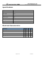
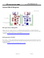
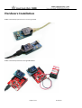
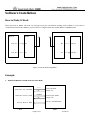
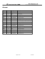
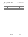
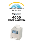
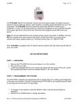
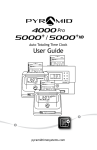
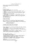
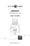
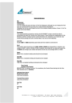
RFBee User Manual v1.0
Index
RFBee ........................................................................................................................................................................................ 1
Overview ................................................................................................................................................................................... 2
Specifications............................................................................................................................................................................ 3
Electrical Characterstics ........................................................................................................................................................... 3
System Block Diagram.............................................................................................................................................................. 4
Microprocessor-Atmega168 ............................................................................................................................................ 4
RF Transceiver-CC1101 ................................................................................................................................................... 4
Hardware Installation............................................................................................................................................................... 5
Software Installation................................................................................................................................................................. 6
How to Make It Work ....................................................................................................................................................... 6
Example ..................................................................................................................................................................... 6
AT Command .................................................................................................................................................................... 8
AT Format: ................................................................................................................................................................ 8
Supported command:............................................................................................................................................... 9
Note: .................................................................................................................................................................................. 9
How to Update Firmware through Arduino.................................................................................................................. 10
Pinout...................................................................................................................................................................................... 11
Revision History ..................................................................................................................................................................... 12
Page 1 of 12
3/17/2010
Overview
RFBee is a RF Module providing easy and flexible wireless data transmission between devices. You may reach most
common RF module functionality via concise AT Command set. You may plug it into any Xbee socket for quick
replacement, and it also have native AVR atmega168 working as a full functional Arduino.
Indoor/Urban: up to 50m; Outdoor line-of-sight: up to 120m;
Receiver Sensitivity: -95dBm
RF Data Transmission Rate:1,200bps; 76,800bps
Working Frequency : 868MHz~915MHz
Communication type: Point to Point, or Point to Multipoint.
Easy-to-Use Serial Interface and rich extendable ports
Easy-to-Use AT Command: Set working mode, Serial Baud Rate, etc.
Open source of Hardware and Firmware
Source files and documents are licensed under a Creative Commons Attribution 3.0 Unported License.
Page 2 of 12
3/17/2010
Specifications
Microprocessor
Atmega168
PCB size
24.38mmx32.94mmx0.8mm
Indicators
No
Power supply
+3.3v
IO counts
9
ADC input
2
Program interface
USB
Connectivity
Compatible with XBee
Communication Protocol
Uart
Operating Frequency Band
ISM 868MHz~915MHz
Outline Dimension
24.38mmx32.94mmx15mm
Electrical Characterstics
Specification
Min
Typ
Max
Unit
Input voltage
3
3.3
3.6
VDC
Transmit Current
34.5
mA
Receive Current
18.1
mA
Idle Current
5.2
mA
Power-down Current
<1
uA
Operating Temperature
-50
Page 3 of 12
125
°C
3/17/2010
System Block Diagram
Microprocessor-Atmega168
Atmega 168 has enough resources to implement the RF controlling while providing complete Uart
communication. More importantly they are the most popular MCU among open source hardware community, making
it compatible to Arduino IDE and the vast knowledge pool.
>>Datasheet: http://www.atmel.com/dyn/resources/prod_documents/doc2545.pdf
RF Transceiver-CC1101
The CC1101 is a low-cost sub-1 GHz transceiver designed for very low-power wireless applications. The circuit is
mainly intended for the ISM (Industrial, Scientific and Medical) and SRD (Short Range Device) frequency bands at 315,
433, 868, and 915MHz.
>>Datasheet: http://focus.ti.com/docs/prod/folders/print/cc1101.html
Page 4 of 12
3/17/2010
Hardware Installation
RFBee controlled by Hyperterminal on PC through UartSB.
RFBee controlled by Seeeduino through XBeeShield.
Page 5 of 12
3/17/2010
Software Installation
How to Make It Work
When powered on, RFBee will send “ok” through serial port. The default working mode is IDLE, so if you want to
communicate between two RFBees, you need first to configure them into TRANS, RECV, or TRANSV mode.
MCU A
RFBee
RFBee
MCU B
Uart_Tx
Rx
Rx
Uart_Tx
Uart_Rx
Tx
Tx
Uart_Rx
RF End A
RF End B
Figure 3 Two RF Ends using RFBee
Example
1. Make both RF End A and B work in Transv Mode
Send enter AT command
“+++”
“ok”
“ATMD3”
Send enter Transv mode
“ok”
Enter AT Mode
Reply “ok”
Enter Transv Mode
Reply “ok”
Receive and Send Data
Send or Receive Data
MCU
RFBee
Page 6 of 12
3/17/2010
Figure 4 Make two RFBee work in Transv Mode
Step1: MCU sends “+++” to RFBee, and RFBee enters AT command mode whenever it receives “+++”. If right, it will
reply with “ok”, otherwise with “error”.
Step2: After receiving “ok”, MCU sends “ATMD3” to RFBee to make it into Transv mode. If right, it will reply with “ok”,
otherwise with “error”. Also you can do some other configurations using the AT command before into Transv mode.
Step3: After receiving “ok”, MCU of RF End A can sends or receives data to or from RF End B. The received data
package format is shown in the next section.
2. Make RF End A work in Trans Mode and RF End B in Recv Mode
For RF End A:
Step1: MCU sends “+++” to RFBee, and RFBee enters AT command mode whenever it receives “+++”. If right, it will
reply with “ok”, otherwise with “error”.
Step2: After receiving “ok”, MCU sends “ATMD1” to RFBee to make it into Trans mode. If right, it will reply with “ok”,
otherwise with “error”.
Step3: After receiving “ok”, MCU can sends data to RFBee End B through Uart.
For RF End B:
Step1: MCU sends “+++” to RFBee, and RFBee enters AT command mode whenever it receives “+++”. If right, it will
reply with “ok”, otherwise with “error”.
Step2: After receiving “ok”, MCU sends “ATMD2” to RFBee to make it into Recv mode. If right, it will reply with “ok”,
otherwise with “error”.
Step3: After receiving “ok”, MCU can receives data from RFBee End A through Uart.
Received Data Package Format:
length
dstAddr
srcAddr
Payload
RSSI
length = dstAddr(1 byte)+srcAddr(1byte)+payload(nbyte)+RSSI(1byte)
dstAddr:
When address check is applied (ATAC1), dstAddr is used by RFBee to compare with address of itself. If they are equal,
RFBee will accept the package and then send it to MCU through Uart, otherwise the package will be dumped.
When address checking is not applied (ATAC0), RFBee will always accept the package whatever dstAddr is.
srcAddr:
Indicates the package is transmitted from which RFBee.
Payload:
Data that you want to transmit.
Max payload length = 32;
Minimal payload length = 1 when threshold=0, otherwise payload length = threshold;
RSSI: Received Signal Strength Indicator. One byte signed data, unit dBm.
Page 7 of 12
3/17/2010
3. Make RF Ends work in Point-to-Mutipoint.
End B
Address: 2
End C
End A
Address: 3
Address: 1
End D
Address: 4
For End B, C, D:
Step1. Send “+++”: Make RFBee into Command mode;
Step2. Send “ATAC2”: Set Address check and with broadcast, so that it will accept packages with broadcast dstAdress
0x00.
Step3. For End B send “ATMY2” to set address ‘2’; For End C send “ATMY3” to set address ‘3’; For End D send “ATMY4”
to set address ‘4’;
Step4. Send “ATDT1” to set address of destination ‘1’.
Step5. Send “ATMD3”: Make RFBee into Transv mode;
For End A:
Step1. Send “+++”: Make RFBee into Command mode;
Step2. Send “ATAC1”: Set Address check, no broadcast.
Step3. Send “ATMY1”: Set address of itself ‘1’;
Step4. Send “ATDT0”: Set a broadcast address, which means data transmitted from End A can be accepted by End B, C,
and D.
Step5. Send “ATMD3”: Make RFBee into Transv mode;
AT Command
AT Format:
AT + Comand(ASCII) + parameter(optional, character)
Example:
ATBD1 - Set Uart Baudrate of RFBee to 19200, return “ok” if success, otherwise “error”.
ATBD - Get Uart Baudrate of RFBee, return “19200” and “ok” if success, otherwise “error”.
Page 8 of 12
3/17/2010
Supported command:
Parameter
(character)
Command
Specification
Set whether RFBee checks the incoming packet
address or not.
0:No address check
1:Address check, no broadcast
2:Address check and 0(0x00)broadcast
Set RFBee itself address (return parameter in hex).
Set specific address of RFBee whose package can be
accepted (return parameter in hex).
Set RF transmitting power.
0:-30dBm,1:-20dBm,2:-15dBm,3:-10dBm,
4:0dBm,5:5dBm,6:7dBm,7:10dBm
Set Uart Baudrate of RFBee.
0: 9600bps,1: 19200bps,2: 38400bps,3: 115200bps
Set working mode of RFBee.
0: idle mode,1: trans mode,2: recv mode,3: transcv
mode,4: sleep mode,5: command mode
Set threshold that will trigger RFBee starting to
transmit (return parameter in hex).
0: transmit as soon as RFBee receive data from MCU.
Set RF transmitting DataRate.
0: 76800bps,1: 1200bps
AC
0-1
MA
0-255
DA
0-255
Power
Amplifer
PA
0-7
UART
BD
0-3
Working
Mode
MD
0-5
Transmitting
Threshold
TH
0-32
RF DataRate
DR
0-1
Restore
Default
Settings
RS
-
Restore parameters into default settings.
FV
HV
-
Firmware version
Hardware version
Adressing
Version
Default
Type
0
r/w
0
r/w
0
r/w
7
r/w
0
r/w
0
r/w
4
r/w
0
r/w
-
r
v1.0
v1.0
r
r
Note:
1. When RF DataRate is 1200bps, the minimal transmit interval is about 1ms,;
2. The best way to make RFBees work steady is to make them work in trans or recv mode, as it may drop some
packages in transv mode sometimes.
Page 9 of 12
3/17/2010
How to Update Firmware through Arduino
1. Connect RFBee to UartSB, move switches to XBee and 3.3v, then connect it to your computer through USB cable.
UartSB link:
http://www.seeedstudio.com/depot/uartsb-v22-a-much-more-powerful-usb-to-serial-converter-p-495.html?cPath=35
2. Download the source code of RFBeev1.0, decompress it to your working directory.
http://www.seeedstudio.com/depot/datasheet/RFBEE.rar
3. Modify the Arduino library. Enter your Arduino installation directory (if you use Arduino 0017 ):
..\arduino-0017\hardware\cores\arduino.
Backup file HardwareSerial.cpp and HardwareSerial.h before do any changes on them. Then replace them with
two new files downloaded from here. http://www.seeedstudio.com/depot/datasheet/HardwareSerial.rar
4. Open your Ardunio, open the RFBeev1.0 project. Select Tools->Board->Ardunio Pro or Pro Mini (3.3v, 8MHz)
w/ATmega168. Choose the recognized serial port, and then you can program your RFBee firmware by yourself.
Page 10 of 12
3/17/2010
Pinout
PIN
3V3
TX
RX
PD4
!RESET
PB1
PB0
PD7
!DTR
GND
PC3
PC2
PC1
VREF
PC0
ADC7
PD5
PD6
PC5
PC4
#
1
2
3
4
5
6
7
8
9
10
11
12
13
14
15
16
17
18
19
20
Pad Type
Supply input
Output
Input
Input/Output
Input
Input/Output
Input/Output
Input/Output
Input
GND
Input/Output
Input/Output
Input/Output
Input
Input/Output
Input
Input/Output
Input/Output
Input/Output
Input/Output
Description
Vcc,+3.3v
Uart Tx port
Uart Rx port
ATmega168 PD4
ATmega168 Reset port
ATmega168 PB1
ATmega168 PB0
ATmega168 PD7
Used for programming ATmega168
GND
ATmega168 PC3
ATmega168 PC2
ATmega168 PC1
ATmega168 AREF port
ATmega168 PC0
ATmega168 ADC7
ATmega168 PD5
ATmega168 PD6
ATmega168 PC5
ATmega168 PC4
Page 11 of 12
3/17/2010
Revision History
Rev.
Descriptions
V1.0
Initial design
2010/03/05
V1.01
Modify AT command DR and MD specifications
2010/03/15
Page 12 of 12
Release date
3/17/2010