1
SNK
>
)
~
WARNING
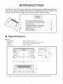
• Be sure to read this user's manual before use.
• Keep this manual nearby when operating this cabinet.
1)
()
INTRODUCTION
The MV-1 B 1-slot PCB can be used with cabinets meeting JAMMA specifications.
This user's manual contains information on operating the MV-1 B. Before use,
please carefully read through the manual for proper usage methods.
( Index )
Introduction/Specifications ........... 1
Precautions for safe operation ....... 2
Parts names ..................... ... 4
Installing software cartridges ......... 5
Using the setting modes ............. 6
Main harness ..................... 12
Wiring diagram .................... 13
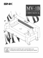
11 Specifications
MV-18
Power source
Dimensions
Weight
Accessories
DC +5 V 3A/DC +12 V 1A
266 mm (W) x 125 mm (D) x 100 mm (H)
550 g (without software cartridge)
User's manual x 1
F,;;,;r~-=-~:-=.:.~:~"§--;,-;.~~-;.-;.~~~·~.-;.:~
....
.:'
:
:
I
i
(
&
)
,
I
i
:
l _ _________ l _________ __J
-----266------
* Design and specifications are subject to change for product improvement without notice.
1
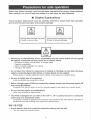
Precautions for safe operation
Before use, please carefully read through these precautions for proper usage methods.
After reading it, be sure to keep the manual in a safe place for later reference.
•
Display Explanations
The procedures listed herein must be carefully followed to ensure both safe operation
and to prevent personal injury and property damage.
r
Lt
Lt
Danger
Warning
Ignoring these warnings may result
in injury or property damage.
Ignoring these warnings may result
in death or serious injury.
\...
Danger
• Should any of the following occur, immediately turn the power switch off and unplug
the cabinet. Continued use may cause fire or electric shock.
-
Emissions of smoke, unusual odors, or strange noises
Operation irregularities
Water or foreign materials in the cabinet
Damage to the cabinet
• Do not place the cabinet in areas prone to leaking or flooding; do not allow the place
objects containing liquid (like drinks) or metal objects on the cabinet.
Should liquids or metallic objects fall into the cabinet, it may cause fire or electric shock.
• Be sure to tightly join all connectors.
Loose connections may cause fire or shock.
• Before changing game PCBs and conducting cabinet checks, turn the power switch off
and unplug the cabinet.
Changing PCBs with the switch on and the cabinet plugged in may cause fire or electric shock.
• Do not conduct repairs or modifications.
These may cause fire or electric shock.
• This PCB is designed for use with an AC 100 V ± 1O V current; be sure to connect its
power plug to a specialized outlet.
Connecting a number of appliances that consume a lot of power to the same electric outlet (like air
conditioners and other cabinets) may cause fire or electric shock.
MV-18 PCB
• Guard against dust and conductive materials entering into the slot.
This may cause fire or electric shock.
2
Warning
• Do not mount the cabinet containing the MV-18 or place heavy objects on it.
This will not only cause injury should it become unbalanced and tip over or fall, but it may cause
damage to the cabinet.
• Under no circumstances place the cabinet with the MV-18 outside.
-This will cause damage or breakdowns.
• Never place the cabinet with the MV-18 in the following locations as it may cause breakdowns.
- Indoor pools or areas near a shower where humidity is high and there is a danger of internal
condensation.
- In areas exposed to direct sunlight.
- Near areas of excessive heat, like next to a heater, and around dangerous materials.
- In places that are excessively dusty.
• When unused for long periods, turn the cabinet with the MV-18 off and unplug it for
safe storage.
• Place the cabinet where room temperature is between 5°C and 40°C.
Breakdowns may result with operation outside the given temperature range.
• During shipping or moving, avoid serious jolts to the MV-18.
This may cause damage or breakdown.
• Always use a Logic tester when checking IC port circuitry.
Using a normal tester may cause damage or breakdown.
• When installing the PCB, be sure to calibrate the 4 lower adjusters to bring the cabinet
with the MV-18 level.
Should the cabinet tip over or fall, it may cause injury.
• Be sure to connect a ground cable to the ground terminal.
MV-1 B PCB tips
• When inserting game cartridges, always turn the power OFF.
Inserting cartridges with the power on may cause breakdowns.
• Do not insert non-MVS game cartridges or NEO GEO home use cartridges into the slot.
This may cause breakdowns.
• Insert game cartridges securely into the slot.
This may cause breakdowns if not properly inserted.
• After inserting game cartridges, be sure to check operations.
• Using the unit near televisions, radios, or portable communications devices may interfere with their signals. If so, place these devices away from the unit.
3
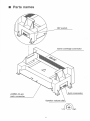
11 Parts names
DIP switch
Game cartridge connector
8-pin connector
JAMMA 56-pin
main connector
Speaker volume dial
4
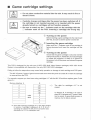
II Game cartridge settings
~
• Do not place conductive material into the slot. It may result in fire or
electric shock.
Danger
• Carefully change cartridges after the. power has been switched off. If
the cartridge is not inserted securely or is inserted with the power
already turned on, cartridges will not function properly.
• Be sure to match up the 6 indicator mark ori the cartridge with the
6 indicator mark on the PCB. Inserting a cartridge the wrong way
~
Warning
CD Turning on the power
Before inserting a game cartridge into the main board
(MV-1 B), be sure to see the power is turned off.
® Inserting the game cartridge
Make sure the 6 indicator mark of the cartridge is
facing downward and insert the cartridge into the
slot.
@ Turning on the power
Check that the game cartridge is securely inserted
and turn the power on. At this time, if unusual images
or noises are produced, or there is no picture on
the screen, turn off the power and reinsert the game
cartridge.
This PCB is designed for the sole use of NEO GEO Multi Video System cartridges; NEO GEO Home
System is incompatible with these slots. Use only NEO GEO MVS cartridges!
Failing to follow the steps above may cause faulty operation or damage to both cartridge and PCB parts.
*The MV-1Bstores7 types of game income totals even when the power is turned off or when the cartridge
is removed from the PCB.
For example, suppose you have been using cartridges A-F with the MV-1 Band then replace game F with
game G ...
Memory directory A
B
¢
A
B
The data for cartridges A-F is not
erased.
c
D
E
.....
E
F
MVS
F
In diagram B, if cartridge H is used in
place of G, because only 7 types of data
can be saved, G game data remains in
memory, but A data is erased.
G
H
~
Even after removing cartridges A-F, their data remains
in memory. If cartridge G replaces A, B, C, D, E or F,
operating the cabinet will still permit cumulative data
calculation for A-G in subsequent use.
5
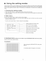
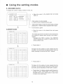
11 Using the setting modes
Unlike previous PCBs, for which settings were made using DIP switches on the PCB, with the Multi Video
System (MVS) these settings are made using the control panel and the monitor screen. Income statistics
for the various games can also be kept. The following is an explanation of modes and how settings are
made.
1. Entering the setting modes
•
•
After turning the cabinet on, press the test switch to call up the main menu.
Switch DIP switch 1 on top of the PCB is turned ON, the main menu will also appear the next time the
power is turned on.
2. Main menu
Use the control panel (Player 1 side) to set the various modes.
• Move the joystick up and down to move the cursor. Match the cursor to the item you wish to set and
press the A button to set it.
·
*Use the control panel (Player 1 side) to make all mode settings.
Adjusts switches and monitor color .
.,.. HARDWARE TEST
HARD DIP SETTINGS
SOFT DIP SETTINGS
INCOME DATA ~~~~~--f~~~~~
CALENDAR SETTINGS
EXIT
?/?/96 ??:??:??
Main PCB DIP switch settings.
Sets credits and game difficulty.
Displays play counts and coins totals.
Adjusts date and time settings.
Returns to the main screen.
Machine time display
3. Hardware test (If software is not loaded, only the HARDWARE TEST mode can be used.)
Carries out the various cabinet checks.
Crosshatch
After choosing the HARDWARE TEST mode, press
·
button A.
A crosshatch pattern will appear on the screen.
6
1
•
Press the start button on the Player 1 side of
the control panel to bring up the screen below.
Screen color adjustment
RED
GREEN
BLUE
WHITE
DODD
•
1
1/0 CHECK
DIP switches
I / 0 CHECK
Pl P2
1123456 781
----uP
DOWN
LEFT
RIGHT
PUSHl
PUSH2
PUSH3
PUSH4
START
SELECT
0
0
0
0
0
0
0
0
0
0
0
0
0
0
0
0
0
0
0
0
The RGB colors will be displayed.
• Use this display to adjust screen color.
The various switches on the control panel and
elsewhere can be checked.
•
00000000
COINl
COIN2
SERVICE
TEST
0 ---+0
0
0
Press the start button on the Player 1 side of
the control panel.
"O" indicates that the switch is OFF, while "1"
indicates ON. Operate the various switches to
verify that they are displaying correctly.
Coin Selector
Service switch
Test switch
Control panel buttons
Backup clear
1
BACKUP CLEAR
OK=PRESS A, B, C BUTTONS
AT ONE TIME
•
Press the start button on the Player 1 side of
the control panel.
Press buttons A, B, and C simultaneously on the
Player 1 side to clear data like income totals, etc.
(memory is returned to its status upon shipment
from the factory).
Erased data includes:
• Income totals (play and coin counts)
• Software DIP settings (play counts, coin counts,
game difficulty)
7
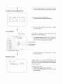
11
Using the setting modes
l
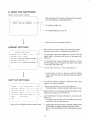
SETTING UP THE CALENDAR
CURRENT TIME
17 / 2 / 96 SAT
19:30:41
THE TIME TO BE SET UP
A BUTTON,JOYSTICK=SELECT
D BUTTON=SET
17 / 2 / 96 19:30:41
l
RETURN TO CROSS HATCH
•
Press the start button on the Player 1 side of the
control panel.
To set the calendar
• Use the joystick to highlight in red the number you
wish to change. Press button A to go to a higher
number and button B to go to a lower one. After you
are finished making these settings, be sure to save
them with button D.
*The date and time are already set at the factory.
There is usually no need to set them.
•
Press the start button on the Player 1 side of the
control panel.
* To return from the hardware test mode to the main
menu or game screen, turn the power off and back
on again. (You cannot return using the buttons.)
4. HARD DIP SETTINGS
The PCB DIP switch settings are displayed on screen.
SETTING UP THE HARD DIP
12345678
SETTING MODE 1.. . .. . . ON
CONTROLLER
.. 0 . . . . . NORMAL
COMMUNICATION . .. 000 . . OFF
FREE PLAY
. .... . 0. OFF
STOP MODE
. . . . . . . 0 OFF
O=ON l=OFF
After making hard DIP switch settings with the
joystick, save the settings by pressing button A. ·
Press button C to return to the main menu .
8
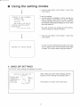
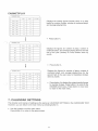
5. SOFT DIP SETTINGS
Adjusts various game settings.
After making soft DIP switch settings with the joystick,
save the settings by pressing button A .
._.
SETrr:ING UP THE CABINET
SLOTl ART OF FIGHTING
I L
For setting credits, etc.
L
j
l
For setting difficulty levels, etc.
•
Move the cursor and press button A.
CABINET SETTINGS
Sets number of coins required and number of plays.
(Increase with button A, decrease with button B.)
SETTING UP THE CABINET
For free play, even with credits at 0, you can use the
select button. (Increase with button A, decrease with
button B.)
COIN RATE 1 COIN= 1 CREDIT
COIN RATE 2 COIN= 2 CREDITS
GAME START COMPULSION 30 sec
- - - - - + - - - - To determine the interval between insertion of coins
and the beginning of the game. (Increase with button
A, decrease with button B.)
To turn demo sound on or off. (Use button A.)
l
SOFT DIP SETTINGS
•
Press button C once to return to soft DIP setting
menu. Move the cursor to the desired item and press
button A.
- - To limit the number of plays in continuous play. (Use
button A to change settings.)
CONTINUE
4time('"'WITHOUT• •FREE) -----+--'
DEMO SOUND
YES (, .. NO)
HOW TO PLAY
YES (•- •NO)
DIFFICULTY
LEVEL 4
BONUS RATE
SECOND BONUS ( • •EVERY• •NO)
BONUS
100000 / 200000
L
HERO
* Items will vary slightly based on game titles.
To turn demo sound on or off. (Use button A.)
* Settings made in cabinet setting mode have priority.
Select whether or not playing instructions appear at the
beginning of a game. (Use button A.)
Level of difficulty (Increase with button A, decrease with
button B.)
*The higher the number, the more difficult the game
and the shorter the playing time.
•
Press button C once to return to soft DIP setting menu.
Press button C again to return to the main menu.
* Be sure to press button C after making game selection.
9
Using the setting modes
11
6. INCOME DATA
To display the number of plays, number of coins, etc.
ti>-
CABINET / COIN
CABINET / PLAY
SLOTl ART OF FIGHTING3
SLOT2 SAMURAI SPIRITS
SLOT3 KING OF FIGHTERS
SLOT4 MAHJONG
•
Move the cursor to the desired item and press
button A.
Total number of coins inserted
( 1 week/1 st half of year/2nd half of year)
Total number of plays, number of continue plays, average
playing time (1 week/1st half of year/2nd half of year)
- - Income.data by game
CABINET/COIN
•
CABINET / CO IN
COINl
COIN2
FEB / 17
02244
0
25
F EB/ 1 6
04422
0
36
FEB/15
06633
0
47
FEB/14
08844
0
48
FEB/13
02399
0
29
F EB/12
05699
0
94
Move the cursor to the desired item and press
button A.
SERVICE
The weekly figure for the number of coins inserted into
the machine is broken down by day in the COIN 1
column.
* Disregard the COIN 2 column. The SERVICE
column indicates the number of credits when the
service switch is set.
/
•
CAB INET / COIN
SERVICE
COINl
COIN2
JAN
42244
0
25
FEB
4 4422
0
36
MAR
56633
0
47
APR
68844
0
48
MAY
72399
0
129
JUN
55699
9
294
The figure for the number of coins inserted into the
machine in the first half of the year is broken down by
month (January to June) in the COIN 1 column.
•
CABINET / CO IN
COINl
COIN2
SERVICE
JUL
42244
0
25
AUG
44422
0
36
SEP
56633
0
47
OCT
68844
0
48
NOV
72399
0
129
DEC
55699
9
294
Press button A.
Press button A.
The figure for the number of coins inserted into the
machine in the second half of the year is broken down
by month (July to December) in the COIN 1 column.
•
10
Press button A to display original weekly figures for
number of coins. Press button C to return to the
INCOME DATA menu. Press button C once more
to return to the main menu.
CABINET/PLAY
CABINET / PLAY
PLAY
CONT .
FEB / 12 MON
42
33
FEB/ 11 SUN
74
55
FEB/ 10 SAT
96
77
FEB/
88
11
F EB / 8 THU
53
32
FEB / 7 WED
56
55
FEB /
88
11
9 F RI
6 TUE
AV.TIME
Displays the weekly figures (broken down on a daily
basis) for number of plays, number of continued plays,
and average playing time.
!
•
Press button A.
CABINET I PLAY
PLAY
CONT .
JAN
42244
33363
F EB
44422
35543
MAR
56633
3 7773
AP R
68844
39983
MAY
72399
33232
JUN
55699
1 55 1 9
AV .T IME
Displays the figures for number of plays, number of
continued plays, and average playing time for the first
half of the year (January to June) broken down by
month.
!
•
CABINET / PLAY
)
PLAY
CONT .
JUL
42244
333 63
AV . T I ME
AUG
44422
~5543
SEP
5 6633
OCT
68844
NOV
72399
a
129
DEC
55699
9
294
25
Press button A.
Displays the figures for number of plays, number of
continued plays, and average playing time for the
second half of the year (July to December) broken
down by month.
36
47
0
48
•
Press button A to display the original weekly figures
for number of plays. Press button C to return to the
INCOME DATA menu. Press button C once more
to return to the main menu.
7. CALENDAR SETTINGS
This function and manner of setting are the same as CALENDAR SETTINGS in the HARDWARE TEST.
However, you can return to the main menu by pressing button C.
•
Use the joystick to exit the main menu.
Press button A to return to the game screen.
11
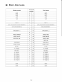
11 Main Harness
Solder points
Terminal
number
Part name
GND
A
1
GND
GND
B
2
GND
v
+5 v
c
3
+5
D
4
E
5
F
6
(Key to prevent incorrect insertion)
H
7
(Key to prevent incorrect insertion)
(COIN COUNTER 2)
J
8
COIN COUNTER 1
K
9
L
10
M
11
VIDEO GREEN
N
12
VIDEO RED
VIDEO SYNC
p
13
VIDEO BLUE
SERVICE SW
R
14
VIDEO GND
s
15
TEST SW
COIN SW 2
T
16
COIN SW 1
START SW 2
u
17
START SW 1
2P UP
v
18
1P UP
2P DOWN
w
19
1P DOWN
2P LEFT
x
20
1P LEFT
2P RIGHT
y
21
1P RIGHT
2P PUSH 1
z
22
1P PUSH 1
2P PUSH 2
a
23
1P PUSH 2
2P PUSH 3
b
24
1P PUSH 3
2P PUSH 4
c
25
1P PUSH 4
d
26
GND
e
27
GND
GND
f
28
GND
+5
+12
v
SPEAKER(-)
12
v
+5 v
+12
v
SPEAKER(+)
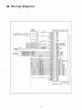
11 Wiring diagram
POWE~
NEO-MVH MV-18 PCB
SuPPLY
GNO
GNO
GNO
GNO
AC
GNO
~sv
+5V
+SV
+SV
-·-
AC
-+-l2V
+12'1
~5I'N
COIN COUNTtR<ll
'cou"NTEF<i
CO!N COUNTER2
(Gi~Ol
CO!N
(GNQJ
SPEAKER(+l
SPEFIKER!-1
SPEAKER I
(SC)
V
7GN01
V!DEO ~EC)
v!DEO GREEN
VIDEO aLL.;E
'/!QECl :YNC
'/!DEO :3NO
SERV!CE SW
... ..-.
TEST :3W
C:J!N SWl
C:OIN SW2
PLAYE~l STAQT SW
PLAYE!=l2 STA~T 5W
PLHYERl UP
PLAYER2 WP
PL::.YERl OCWN
PLAYER2 DOWN
PLAYERl 1..EFT
PLAYER2 ~EFT
CLAYERl ~IQ-IT
,::ILAYER2 ~IGHT
PLAYEl=l1 PUSH A
PLAYER2 PUSH A
PLAYEFU PUSH a
PUWE!=l2 PUSH 8
PLAYERl PUSH C
,::ir_AYER2 iJUSt-1 C
PLAYEl=ll PUSH D
PLAYER2 PUSH D
"GNoGNO
I
:;NO
I
GNO
l
,..,.,i
,J,
NEO-MVH SLOT 1B PCB
13
S-9607
The Future Is Now
mNK
SNK CORPORATION
SNK BLDG. , 18-12 TOYOTSU-CHO , SUITA-SHI, OSAKA, 564, JAPAN
TELEPHONE : (81) 6-339-5577
FAX: (81) 6-338-7175
SNK CORPORATION OF AMERICA
20603 EARL STREET, TORRANCE, CA 90503, U.S.A.
TELEPHONE: (1) 310-371 -7100
FAX: (1) 310-371-0969
SNK ASIA LIMITED
SUITE 807, TOWER 1. THE GATEWAY, 25 CANTON ROAD, TSIM SHA TSUI, KOWLOON , HONG KONG
TELEPHONE: (852) 2-730-0420
FAX: (852) 2-375-3203
SNK EUROPE LIMITED
11 ALBEMARLE STREET, LONDON WIX 3HE , ENGLAND
TELEPHONE: (44) 171-629-0472
FAX: (44) 171-629-0474
NEO GEO DO BRASIL L TDA.
AV . EUCLIDES, 56-JABAOUARA CEP; 04326-080-SAO PAULO-SP BRAZIL
TELEPHONE: (55) 11-588-2300
FAX: (55) 11-588-2790
Printed in Japan