1
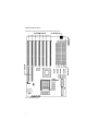
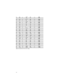
USER’S MANUAL
.....................................
Nx586 VESA/ISA System Board
July 26, 1995
NOTICE
©Copyright 1995 NexGen Inc.
ALL RIGHTS RESERVED
DOCUMENT NO. MAN-XXXX-XXXXXX
Document Revision July, 95
No part of this document may be photocopied, reproduced, stored in a retrieval system, transcribed or
translated to another language, in any form or by any means, electronic, mechanical, magnetic, optical,
chemical, or otherwise, without the prior written consent of NexGen Inc.
NexGen Inc. reserves the right to revise this document and make changes in the specifications of the product
described herein at any time without notice and without obligation to notify any person of any such revision or change.
NexGen™, Inc. makes no warranty, express, implied or statutory concerning this document or its use and assumes
no responsibility for any omissions or errors which may appear in this document nor does it make a commitment to
update the information contained in this document.NexGenô, INC. SPECIFICALLY DISCLAIMS LIABILITY FOR
INCIDENTAL OR CONSEQUENTIAL DAMAGES RESULTING FROM THE ACQUISITION, USE OR SALE OR
OTHER TRANSFER, PERMITTED OR OTHERWISE, OF THIS DOCUMENT OR THE USE OF THE PRODUCTS
DESCRIBED IN THIS DOCUMENT.
Nexgen and Nx586 are registered trademarks of Nexgen Corporation. AMI is a registered trademark of American
Megatrends, Inc.
First printing - September 1994
WARNING
FOR CONTINUED PROTECTION AGAINST FIRE, REPLACE FUSE WITH SAME TYPE AND RATING. FUSE
RATING: 1A/125V.
THE USER IS CAUTIONED THAT CHANGES OR MODIFICATIONS NOT EXPRESSLY APPROVED BY THE
MANUFACTURER COULD VOID THE USER'S AUTHORITY TO OPERATE THIS EQUIPMENT.
Table of Contents
...................................
INTRODUCTION......................................................................................1
FEATURES......................................................................................................1
ABOUT THIS MANUAL ...................................................................................2
CHECKLIST ....................................................................................................2
HARDWARE SETUP................................................................................3
OVERVIEW.....................................................................................................3
SYSTEM BOARD LAYOUT ...............................................................................4
STEP 1. CONFIGURING THE SYSTEM BOARD ....................................................5
STEP 2. INSTALLING THE SYSTEM BOARD .......................................................5
STEP 3. INSTALLING DRAM MODULES..........................................................6
STEP 4. VESA/ISA-BUS ADAPTER INSTALLATION PROCEDURE.....................7
STEP 5. CONNECTING EXTERNAL PERIPHERALS...............................................7
STEP 6. RUNNING BIOS SETUP ......................................................................7
SOFTWARE CONFIGURATION OF SYSTEM BOARD
COMPONENTS .........................................................................................9
OVERVIEW.....................................................................................................9
AMI BIOS® SETUP ......................................................................................9
RUNNING THE BIOS SETUP..........................................................................10
HARD DISK CONFIGURATION .......................................................................15
ADVANCED SETUP .......................................................................................17
FACTORY RECOMMENDED CMOS SETTINGS (FOR AMI BIOS® USERS) .......22
TECHNICAL REFERENCE ..................................................................25
NX586 SYSTEM BOARD JUMPER SETTINGS...................................................25
CONNECTORS...............................................................................................25
BATTERY OPTIONS.......................................................................................25
NOTES......................................................................................................27
i
(This page is intentionally left blank)
ii
Introduction
...................................
Congratulations on your purchase of theNexGen™ Nx586 system board-- part of the family of highperformance personal computer products fromNexGen™. This motherboard has been designed to fit
in most standard AT and baby-AT enclosures. To avoid damage to your system please read the
installation section thoroughly before attempting to install the motherboard or configure your system.
This chapter describes the features of the Nx586VESA/ISA system board. This chapter also
provides an overview of this manual to help you locate information quickly.
Features
The NexGen™ Nx586 system board includes the following features:
•
Supports NexGen Nx586 P80/P90/P100 microprocessors with 32KB internal cache.
•
NexGen NxVL chipset.
•
High performance 256KB write-back secondary cache.
•
Supports up to 192MB of main memory on-boardusing 72-pin SIMM DRAM Fast Page Mode
modules.
•
Two 32-bit VESA compatible local bus expansion slots with bus mastering capability, five 16-bit
ISA Expansion slots.
•
Supports both hardware and software turbo switching.
•
Flash BIOS support for easy upgrading.
•
3-year limited warranty.
1
About This Manual
This manual is organized as follows:
•
The Hardware Setup section describes how to install and set up the Nx586 system board,
memory, and peripherals. Included in this section are the motherboard layout andDRAM
memory table.
•
The Software Configuration section describes the BIOS setup.
•
The Technical Reference section describes the jumper and switch settings for the Nx586
system board.
Checklist
The following items are included with your Nx586 system board package:
•
Nx586 system board
•
this manual
If you suspect that any of the items in the system unit package have been damaged or that items are
missing, contact your reseller immediately.
2
Hardware Setup
...................................
Overview
This section provides instructions for installing and setting up your Nx586 system board, installing
memory modules and VESA/ISA-BUS peripherals.
CAUTION! The procedures described are meant as
general guidelines for the experienced installer. Contact
your dealer if you are unsure about the installation, or if
you need more detailed information about any portion of
the installation.
The installation of your Nx586 system board consists of 6 basic steps (Your installation may vary,
depending on your system configuration):
Step 1.
Configure the system board.
Step 2.
Install the system board into your computer chassis.
Step 3.
Install the DRAM modules.
Step 4 .
Install any internal VESA/ISA peripherals.
Step 5 .
Connect the monitor, keyboard, and other external peripherals.
Run the BIOS Setup program to configure your system board's memory, hard
floppy drive parameters.
Step 6 .
drive and
This section discusses the hardware installation portion of setting up your system (Steps 1 through5).
It also contains a diagram of the system board (see Figure 1-1 System board Layout, next page) for
reference purposes. To run BIOS setup seethe Software Configuration Section for the AMI BIOS®
(Step 6).
3
System Board Layout
Familiarize yourself with the components of the Nx586 system board.
Figure 1 System Board Layout
4
Step 1. Configuring the System Board
The Nx586 system board options are configured through both software/BIOS and hardware jumpers.
The software/BIOS configuration settings are discussed in the Software Configuration section of this
manual and the Technical Reference section of this manuallists all of the jumper settings for the
Nx586 system board. We do not recommend changing ANY jumper settings unless the user is an
experienced installer -- misuse of jumper settings can result in system board failure and/or loss of
warranty.
Step 2. Installing the System Board
Make sure to observe precautions for handling
static sensitive devices. Static electricity can harm
components on your Nx586 system board and cause system
failure.
CAUTION!
The Nx586 system board is designed to fit into most standard AT/Baby AT enclosures.Follow the
instructions for your particular chassis in order toinstall the Nx586 system board. Make sure your
chassis power supply can generate adequate power for your system board and peripherals. For safety
purposes, NexGen™ recommends using only chassis' that employ UL-Listed power supplies.
WARNING:
The Nx586 processor requires
adequate air flow to dissipate the heat generated by
the processor. Make sure that the processor fan is
not obstructed and is operational. If the fan is not
working, return the board to your dealer for an
exchange.
5
Step 3. Installing DRAM Modules
The Nx586 system board accommodates six72-pin 32-bit or 36-bit DRAM SIMM modules. When
installing memory, the DRAM speed must be 70ns or faster, must support fast-page mode. The six
SIMM slots are labeled in pairs as SM1/SM2 - Bank A, SM3/SM4 - Bank B and SM5/SM6 - Bank C.
The banks may be populated in any order (Bank C then Bank A then Bank B etc..) but both SIMMs
within a bank must be installed at the same time with the same density (1M, 2M, 4M ...) of DRAM
module. Any of the following single density SIMMs (1M, 4M or 16M) or double density (2M, 8M or
32M) SIMM modules may be used. Table 1-1 shows a short list of the possible memory
configurations.
DRAM Configurations
SM1
SM2
1MB x 32
1MB x 32
SM3
8 MB
2MB x 32
2MB x 32
16 MB
4MB x 32
4MB x 32
32 MB
8MB x 32
8MB x 32
2MB x 32
2MB x 32
1MB x 32
1MB x 32
SM5
SM6
TOTAL
24 MB
2MB x 32
2MB x 32
2MB x 32
2MB x 32
32 MB
2MB x 32
2MB x 32
4MB x 32
4MB x 32
48 MB
2MB x 32
2MB x 32
8MB x 32
8MB x 32
...
...
...
...
...
...
...
4MB x 32
4MB x 32
2MB x 32
2MB x 32
1MB x 32
1MB x 32
56 MB
4MB x 32
4MB x 32
2MB x 32
2MB x 32
2MB x 32
2MB x 32
64 MB
4MB x 32
4MB x 32
2MB x 32
2MB x 32
4MB x 32
4MB x 32
80 MB
4MB x 32
4MB x 32
2MB x 32
2MB x 32
8MB x 32
8MB x 32
112 MB
64 MB
80 MB
...
...
...
...
...
...
...
8MB x 32
8MB x 32
4MB x 32
4MB x 32
1MB x 32
1MB x 32
104 MB
8MB x 32
8MB x 32
4MB x 32
4MB x 32
2MB x 32
2MB x 32
112 MB
8MB x 32
8MB x 32
4MB x 32
4MB x 32
4MB x 32
4MB x 32
128 MB
8MB x 32
8MB x 32
4MB x 32
4MB x 32
8MB x 32
8MB x 32
160 MB
8MB x 32
8MB x 32
8MB x 32
8MB x 32
1MB x 32
1MB x 32
136 MB
8MB x 32
8MB x 32
8MB x 32
8MB x 32
2MB x 32
2MB x 32
144 MB
8MB x 32
8MB x 32
8MB x 32
8MB x 32
4MB x 32
4MB x 32
160 MB
8MB x 32
8MB x 32
8MB x 32
8MB x 32
8MB x 32
8MB x 32
192 MB
Table 1 Partial RAM Configuration List
6
SM4
Step 4. VESA/ISA-BUS Adapter Installation Procedure
To install a VESA or ISA -Bus adapter card:
1.
Locate a free VESA or ISA Bus slot on the system board, either a VESA or ISA slot whichever
is appropriate for the card to be installed.
2.
Remove the appropriate expansion slot cover plate from the chassis .
3.
Line up the adapter along the slot to be used and insert the gold-edged connectors into the
connector on the motherboard completely. Make sure that the adapter is well seated in the slot.
Secure the adapter to the chassis with a slot cover screw.
4.
The system should automatically recognize the added adapter. If you have added a video
adapter and wish to use the extended video modes, you may have to install additional drivers
corresponding to the programs and environments used.
Step 5. Connecting External Peripherals
Connect your monitor, keyboard, mouse, AC power cord, and other external devices to your chassis
before powering on the system.
Step 6. Running BIOS Setup
Once the motherboard has been mounted in the case and all of the peripheral connected the final step
is to run the BIOS setup program. When the system is turned on for the first time the BIOS will notice
the addition of DRAM memory and other peripherals and prompt you to enter the setup utility. The
next section of this manual describes the use of the AMI BIOS® Setup utility in configuring your
system. After running Setup, you can proceed with installation of system and application software.
7
(This page is intentionally left blank)
8
Software Configuration
of System Board Components
...................................
Overview
This section describes how to use the included software to configure the components of your system
board. The utilities described include:
AMI BIOS® Setup
Introduction
A program in the ROM (permanent memory) of your system board that configures RAM, date and
time, the type of hard disk connected, and virtually all of the main system level components. The
BIOS Setup values may have already been set prior to shipment.
A record of the system parameters (such as amount of memory, types of disk drives, video display,
numeric coprocessor, and other peripherals) is stored in a special area of memory called CMOS
RAM. When the computer is turned off, a backup battery provides power to the CMOS RAM, thereby
retaining your system configuration.
Each time the system is turned on, it is configured with the values in CMOS RAM, unless the CMOS
RAM was corrupted. The CMOS Setup parameter resides in the CMOS RAM and is available each
time the computer is turned on.
If for some reason, the CMOS RAM is corrupted, the system is configured with the default values
stored in the ROM file. There are two sets of BIOS values stored in the ROM file: the BIOS Setup
default values and the Power-On default values (see this section for more detailed information on
BIOS defaults).
Note: Your system may have been pre-configured prior to
shipment. It is
only necessary to execute the configurationprogram if:
*
You have changed the hardware configuration (i.e.: added
memory, added or removed drives, etc.).
*
The system itself has detected an error while booting up and
requires you to reconfigure CMOS RAM.
Users are not encouraged to run this setup program unless hey
t are familiar with
it. Improper use of this setup program can
result in system failure.
9
Running the BIOS Setup
When the system power is turned on, the computer performs a series of device initializations and
diagnostic tests. During this process, the system will allow you to interrupt the process and run Setup
by pressing the <Del> key. When the Power-On-Self-Test (POST) has completed, the following
message appears:
Press the <Del> key to enter the Setup program.
The table below describes special keys used to perform certain functionswithin the Setup program.
Keystroke
Action
<Esc>
Returns to previous screen or menu, also used to exit
setup.
<Arrow keys>
Moves cursor from one option to the nextwithin a
window or menu.
Alt+H
Displays Help screen
TAB
Move to next window.
Alt+SPACE
Global Exit.
ENTER
Select item highlighted.
Table 2 Keyboard Use - Setup
10
Exiting the Setup Program
When finished making changes within Setup press the <Esc> key until the following menu shown in
figure 2 appears. At this point you are presented with the three choices described below.
Figure 2 Exit Setup Menu.
Save Changes and Exit
This option is used to save the changes made during this sessionin the Setup program then continue
the boot process. After pressing <Enter> with this option highlighted all settings that were modified
are stored in CMOS RAM then a CMOS RAM checksum is calculated and written to CMOS RAM.
Control is then passed to the ROM BIOSand the BIOS either reboots the system (if any new setting
changed the memory map) or continues the boot process.
Do Not Save Changes and Exit
This option passes control to the BIOS without writing any changesmade to the CMOS RAM. Press
<Enter> with this option highlighted to continue the boot process without saving any altered system
parameters.
Continue
Press <Enter> with this option highlighted to return to the main menu of the Setup program.
11
Main Menu Setup Screen
The Setup Main Menu is shown below:
Figure 3 Main Setup Menu.
The Main Setup Menu is divided into four windows each with several submenu options:
•
Setup Window
•
Standard Setup
•
Advanced Setup
•
Chipset Setup
• Utility Window
• Detect Master Hard Disk
• Detect Slave Hard Disk
• Color Set
•
Security Window
•
Password
•
Anti-Virus
• Default Window
• Original Settings
• Optimal Settings
• Fail-safe Settings
Setup Window
This window contains three menus; Standard, Advanced and Chipset. The Standard menupermits
the user to configure and set system components such as time and date, floppy drives,and hard disk
drives. The Advanced menu permits the user toconfigure and set some of the more complex settings
for system components such as floppy drive swapping,system caches, shadow RAM control interrupt
mapping. Finally, the Chipset menu controls some of the hardware specific options of the NxVL
chipset.
12
Utility Window
This window contains three menus; DetectMaster, DetectSlave and Color Set. The DetectMaster
menu allows IDE/EIDE hard disks to be automatically detected configuring the proper number of
heads, cylinders and sectors to make full use of the drive. The DetectSlave menu performs the same
operation for the slave or 2nd IDE hard disk installed in the system. The Color Set menu allows you
to control the color settings for optimal viewing on all type of displays.
Security Window
This window contains two menus; Password and Anti-Virus. The Password menu allows you to set a
password that will be required each time the system is turned on. If you forget your password you will
need to use the CLEAR CMOS jumper to erase the password. Doing this will also clear all of the
other settings which you have made in any of the setup menus. The Anti-Virus option when enabled
issues a warning to the user whenever a program attempts to write to the boot sector of the hard disk
or program attempts to format the hard disk.
Default Window
This window contains three menus; Original, Optimal and Fail-safe. These three menus set all of the
Standard, Advanced, and Chipset settings to preprogrammed values by the factory. Under most
conditions the optimal settings should be used to achieve the best overall system performance. If you
experience any abnormal system behavior try using the Fail-safe settings. If you change your mind
after selecting either the Optimal or Fail-safe settings before you save changes and exit the Original
menu can be used to restore and modified parameters to their original values before exiting.
The remainder of this section details the options and screens available in each of these menus.
13
Standard Setup
This option permits the user to configure and set system components such as time and date, floppy
drives, and hard disk drives. Use the arrow keys to highlight the icon labeled Standard, then press
<Enter>. The following screen appears:
Figure 4 Standard CMOS Setup Menu
Date/Time : This option permits the month, day, year hour, minute, and second stored in CMOS to be
changed. Press <Enter> to bring up the modification screen then move the cursor to the field you wish
to change by using the arrow keys. Change the setting by using ‘+’ and ‘-’ keys or entering the value
directly with the keyboard. The time uses a 24 hour clock format. For P.M. numbers, add 12 to the
hour (4:30 P.M. is 16:30:00).
Supports 720KB, 1.44MB, and 2.88MB 3.5 inch drives; 360KB, and 1.2MB
5.25 inch drives. Move the cursor to either field with the arrow keys and set the appropriate floppy
drive type using the arrow keys then pressing <Enter>.
Floppy Drives A: and B:
Master and Slave H ard Disks: Hard disk types from 1 to 46 are industry standard. The USER type
is user-definable and can be used for boththe master and slave drive. If the USER type is selected,
the user must enter the proper hard drive parameters from the keyboard. The parameters for the
USER type under the master hard disk and slave hard disk can be different, which allows two different
user-definable hard disk drives in the system. Not Installed can be used for diskless workstations.
The two remaining settings are for ESDI and SCSIhard disks.
14
Hard Disk Configuration
Hard drives are available with many different types of interfaces and controller options. The system
BIOS has built in support for several of the most common interface standards: IDE/EIDE, SCSI, ESDI
and ST-506/MFM. In general, depending on the controller used the BIOS needs to be configured to
recognize the hard drives connected.
The most common type of hard disk today uses the IDE or EIDE interface. This type of drive is very
simple to install and configure. The Nx586 system board supports up to four IDE/EIDE hard drives
using a primary and a secondary IDE channel. Each channel supports up to two IDE/EIDE drives or
other IDE devices such as CDROMs or Tape Backup devices.
IDE/EIDE drives can be configured simply by using the DetectMaster and DetectSlave commands in
the Utility Window.
Hard drives are identified by several parameters:
Parameter
Description
Type
The number designation for a drive with certain identification
parameters.
Cyl - Cylinders
The number of cylinders in the disk drive.
Hd - Heads
The number of heads.
WP - Write Precompensation
The size of a sector gets progressively smaller as the track
diameter diminishes. Yet each sector must still hold 512 bytes.
Write precompensation circuitry on the hard disk compensates
for the physical difference in sector size by boosting the write
current for sectors on inner tracks. This parameter is the track
number where write precompensation begins.
Lz - Landing Zone
This number is the cylinder location where the heads will
normally park when the system is shut down.
Sec - Sectors
The number of sectors per track. Hard drives that use MFM
have 17 sectors per track. RLL drives have 26 sectors per
track. RLL and ESDI drives have 34 sectors per track. SCSI
and IDE drives may have even more sectors per track.
Size
The formatted capacity of the drive based on the following
formula:
(Number of heads) x (Number of cylinders) x (number of sectors
per cylinder) x 512 bytes per sector)
Table 3 Hard Drive Configurations
Older ST-506/MFM type hard drives require manual selection of these parameters. The BIOS
provides a table with 46 of the most common parameters for these drives. Also a 47th entry can be
used to enter any configuration not found in the table. Refer to your hard disks manual for the proper
settings if you have this type of drive.
Type
Cyls.
Heads
Write
Precomp
Landing
Zone
Sectors
Capacity
1
2
3
4
5
6
7
8
9
10
11
306
615
615
940
940
615
462
733
900
820
855
4
4
6
8
6
4
8
5
15
3
5
128
300
300
512
512
65535
256
65535
65535
65535
65535
305
615
615
940
940
615
511
733
901
820
855
17
17
17
17
17
17
17
17
17
17
17
10MB
20MB
31MB
62MB
47MB
20MB
31MB
30MB
112MB
20MB
35MB
15
12
13
14
16
17
18
19
20
21
22
23
24
25
26
27
28
29
30
31
32
33
34
35
36
37
38
39
40
41
42
43
44
45
46
855
306
733
612
977
977
1024
733
733
733
306
925
925
754
754
699
823
918
1024
1024
1024
612
1024
1024
615
987
987
820
977
981
830
830
917
1224
7
8
7
4
5
7
7
5
7
5
4
7
9
7
11
7
10
7
11
15
5
2
9
8
8
3
7
6
5
5
7
10
15
15
65535
128
65535
0
300
65535
512
300
300
300
0
0
65535
754
65535
256
65535
918
65535
65535
1024
128
65535
512
128
987
987
820
977
981
512
65535
65535
65535
Table 4 Standard Hard Drive Parameter Settings
16
855
319
733
663
977
977
1023
732
732
733
336
925
925
754
754
699
823
918
1024
1024
1024
612
1024
1024
615
987
987
820
977
981
830
830
918
1223
17
17
17
17
17
17
17
17
17
17
17
17
17
17
17
17
17
17
17
17
17
17
17
17
17
17
17
17
17
17
17
17
17
17
50MB
20MB
43MB
20MB
41MB
57MB
60MB
30MB
43MB
30MB
10MB
54MB
69MB
44MB
69MB
41MB
68MB
53MB
94MB
128MB
43MB
10MB
77MB
68MB
41MB
25MB
57MB
41MB
41MB
41MB
48MB
69MB
114MB
152MB
Advanced Setup
This option permits the user to configure and setsome of the more complex settings forsystem
components such as floppy drive swapping,system caches, shadow RAM control interrupt mapping.
CAUTION! Users are not encouraged to change Advanced
CMOS settings unless they are familiar with doing so.
Improper use of these utilities can result in system failure.
Use the arrow keys to highlight the icon labeled Advanced, then press <Enter>. The following screen
appears:
Figure 5 Advanced CMOS Setup Menu, Page 1 of 4
Typematic Rate : Controls the rate at which keystrokes are repeated if a key is held down. The
selections are 15, 20, 24, or 30 characters per second.
System Keyboard: This option controls whether an error message is generated if no keyboard is
attached. This permits the system to boot without displaying the “Press F1 to continue” message if no
keyboard is attached.
Primary Display: Selects the type of primary display connected to the system. The option are
Monochrome, Color 40x25, Color 80x25 , VGA/EGA/PGA or Not Installed.
Mouse Support:
When enabled this option permits the use of a PS/2 style mouse.
When this option is enabled the entire memory range is tested during the
POST. If disabled only the first 1MB of system RAM is tested with the remaining memory only
checked for size by the POST.
Memory Test Tick Sound: This option enables or disables the “tick” sound heard from the PC
speaker during the memory test routine of the POST.
Above 1MB Memory Test:
Parity Error Check: This option determines whether system DRAM should generate parity check
errors. If your DRAM SIMMs are 32bit non-parity SIMMs this option should be set to disabled. If your
DRAM SIMMs are 36bit parity SIMMs you can set this option to either enabled or disabled.
Hit <DEL> Message Display: Setting this option to disabled will prevent the
Hit <DEL> if you want to run Setup
17
message from being displayed during the system boot process.
This option controls where the hard disk information will be stored in
memory. The options are 0:300 or Top 1K. If Top 1K is selected the hard disk information will be
stored beginning at 639K instead of the normal 0:300 memory location.
Extended BIOS RAM Area:
During the power-on self test of the system if the BIOS detects any
errors it will display the message:
Wait For “F1” If any Error:
Press <F1> to continue
If this option is disabled the boot process will not wait for the F1 key to be pressed before continuing to
boot.
Figure 6 Advanced CMOS Setup Menu, Page 2 of 4
System Boot Up Num Lock:
When set to ON this option turns off the keyboards Num Lock setting
after booting.
Numeric Processor Test:
Enables or disables the detection of a installed numeric coprocessor.
Floppy Drive Seek At Boot:
When set to enabled the BIOS performs a seek command on all floppy
drives before booting.
This option controls the order in which the BIOS looks for a boot
device. The options are [A: then C:] and [C: then A:].
System Boot Up Sequence:
System Boot Up CPU Speed:
This option controls whether the CPU is booted in the Turbo or non-
Turbo mode.
CPU Cache: This option enables or disables the internal and external CPU caches. When set to
disabled both the internal and external CPU caches are disabled.
This option enables the prompting for a password each time the system is
booted or the user exits the Setup utility. The settings are Setup or Always. If Setup is selected the
password prompt will only be asked when attempting to enter the setup utility.
Password Checking:
18
Video Shadow C000,16K:
Video Shadow C400,16K:
These option control the shadowing of the video BIOS area. When enabled the video BIOS ROMs are
copied into system DRAM for faster execution.
Figure 7 Advanced CMOS Setup Menu, Page 3 of 4
19
Shadow C800,16K:
Shadow CC00,16K:
Shadow D000,16K;
Shadow D400,16K:
Shadow D800,16K:
Shadow DC00,16K:
These options control the shadowing of adapter ROMs in the specified areas of memory. Unless you
a re sure no adapter RAM resides in the area you wish to shadow these should remain disabled.
Non-cacheable Region #1:
Non-cacheable Region #2:
These options along with the Base address, Offset and Block Size options permit two areas of
memory to be defined as non-cacheable.
Figure 8 Advanced CMOS Setup Menu, Page 4 of 4
Pri IDE, Disk1: 32-bit mode:
Pri IDE, Disk 2: 32-bit mode:
Block Mode:
LBA Mode:
These settings control the hard disks connected to the primary IDE controller in the system. The 32bit mode setting when enabled uses 32-bit data transfers on the IDE data port. When disabled the
BIOS uses 16-bit data transfers to the IDE drive. In order to make use of 32-bit mode your IDE
controller must also support 32-bit transfers between the controller and the CPU. Block mode enables
the use of multi-sector reads and writes to the selected IDE drive. LBA (Logical Block Address) mode
is a method of addressing hard drives greater than 528MB in size. If you are installing a drive greater
than 528MB LBA Mode must be set to enabled. Also the hard drive must have been formatted and
portioned with LBA Mode enabled in order to operate properly.
Secondary IDE Controller, Disk1:
Secondary IDE Controller, Disk2:
These options tell the BIOS whether additional drives are connected to the secondary IDE controller.
The options are Present and Absent.
Sec IDE, Disk1: 32-bit mode:
Sec IDE, Disk 2: 32-bit mode:
Block Mode:
20
LBA Mode:
Refer to the description for the primary IDE settings above.
Chipset Setup
This option configures chipset-specific features. These parameters have already been optimized for
your system--improper use of this utility could result in system failure. Consult your dealer before
attempting to use this option.
Figure 9 Chipset Features Setup Menu
ISA Bus Speed: This option controls the divisor between the CPU’s clock and the clock sent to the
ISA bus. This option is set automatically to the proper divisor by the BIOS and should not be modified
under normal conditions.
This option forces a hole in the systems DRAM between 14MB and
16MB. Some operating systems may require a hole in this memory space. This option should be set
to disabled for DOS/Windows/OS/2 systems.
Memory Hole 14MB to 16MB:
VL-Bus Transfer Wait State:
This option when enabled forces 1-wait state to be inserted in all VESA
bus operations.
Alternate Instructions: This option should be left disabled.
16 Bit DMA Wait States: This option controls the number of wait states during 16-bit DMA cycles.
This option should be set to 4 Wait States under normal operation.
8 Bit DMA Wait States: This option controls the number of wait states during 8-bit DMA cycles. This
option should be set to 4 Wait States under normal operation.
DMA Clock: This option controls the divisor between the ISA Bus Clock and the DMA controller.
Under normal operation this should be set to ISABCLK.
21
Factory Recommended CMOS Settings (for AMI BIOS® users)
The factory recommended settings are listed below. These settings should be used in the event
CMOS RAM has been corrupted, or for some reason you wish to reset CMOS to the factory’s
recommended settings. However, if your hard disk does not have an operating system, change the
setting at System boot up sequence , to A:,C: . For Adapter ROM shadowing, enable shadow
whenever appropriate (i.e.: adapter card has on-board BIOS).
Advanced CMOS Setup
Typematic Rate Programming
Typematic Rate Delay (msec)
Typematic Rate (Chars/sec)
Above 1M Memory Test
Memory test tick sound
Memory Parity Error Check
Hit <DEL> Message Display
Hard Disk Type 47 RAM area
:Disabled
:500
:5
:Disabled
:Enabled
:Disabled
:Enabled
:0:300
Wait for <F1> if any error
:Enabled
System Boot Up Num Lock
:On
Floppy Drive Seek at Boot
System Boot Up Sequence
:Disabled
:C:, A:
Cache Control
:Enabled
Fast Gate A20 Option
:Enabled
Video
ROM Shadow C000,32K :Enabled
Adapter ROM Shadow C800,16K :Disabled
Adapter ROM Shadow CC00,16K :Disabled
Adapter ROM Shadow D000,16K :Disabled
Adapter ROM Shadow D400,16K :Disabled
Adapter ROM Shadow D800,16K :Disabled
Adapter ROM Shadow DC00,16K :Disabled
System ROM Shadow E&F,128K :Enabled
Non-Cacheable Region
:Disabled
#1
Starting Base
: 0MB
Addr.
: 0MB
Offset
Block Size
: 4KB
Non-Cacheable Region
:Disabled
#2
Starting Base
: 0MB
Addr.
: 0MB
Offset
Block Size
: 4KB
Table 2-4 Advanced CMOS Setup
Advanced NxVL[TM] Chipset Setup
ISA Bus Speed
Memory hole 14meg to 16meg
VL-Bus Transfer Wait State
Alternate Instructions
:CLK/5
16 Bit DMA Wait State
:Disabled 8 Bit DMA Wait State
:0 WS
DMA Clock
:Off
4 Wait
4 Wait
ISABCLK
Note: The ISA Bus Speed setting listed is for the P80 and P90 boards. For the P75
board, set the ISA Bus
Speed to CLK/4. For the P100 board, set the ISA Bus Speed to CLK/6.
22
(This page is intentionally left blank)
23
Technical Reference
...................................
Nx586 System Board Jumper Settings
JP1
Open*
Reserved for future use
JP2
1-2*
Normal
2-3
Clear CMOS
Factory use only
CPU dependent - Do not change from factory
JP3
setting. Warranty void if tampered with.
JP4-1
Closed *
VL-Bus Write wait state (1 WS)
-2
Closed *
VL-Bus > 33MHz
Open
VL-Bus <= 33MHz
Closed *
VL-Bus Burst Support (Read only)
-3
* Default Setting
NOTE: All number settings indicate a closed jumper. e.g. 1-2, 3-4.
Connectors
J1 Reset Switch
J2 Speaker connector
J3 Keylock/Power LED connector
J4 Turbo switch connector
J5 Turbo LED connector
J6&J7 VESA Local bus slots
J15-J21 16-bit ISA slots
P2 Power connector
J22 External battery connector
P3 Keyboard connector
Battery Options
Depending upon the date which your motherboard was built it may have been shipped with two coin
cells on the motherboard or an external battery pack connected to J22. Either option will work fine.
Due to the limited capacity of the coin cells you may experience a loss of CMOS memory within a
year of use. The external battery packs have a much greater capacity and will last up to 4 years under
normal conditions. When the onboard coin cells drain you may replace them with another set of coin
cells or an external battery pack (4.5V or 6V) which ever you prefer.
25
(This page is intentionally left blank)
26
Notes
...................................
27
28