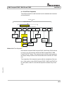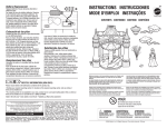
1
SERVICE MANUAL
Test System Versatile Platform
R&S®CompactTSVP TS-PCA3
R&S®PowerTSVP TS-PWA3
Note
Service Manual
for ROHDE & SCHWARZ Test System Versatile Platform
R&S CompactTSVP / R&S PowerTSVP
5th Issue / 08.06 / GB 1152.3914.22
All rights, also translation into foreign languages, are reserved. No part of this manual is permitted
to be reproduced in any form (print, photocopy or any other method), also not for the preparation of
lectures, or processed, reproduced or made available using electronic systems without written permission from ROHDE & SCHWARZ.
® The passing on to third parties and the reproduction of this documentation, utilisation and communication of its contents is not permitted unless specifically approved. Infringements will incur
claims for damages. All rights reserved in the case of the award of a patent or registration of a
design.
R&S® is a registered trademark of ROHDE & SCHWARZ GmbH & Co. KG.
We draw to your attention that the names of software and hardware used in the Service Manual,
and the brand names of the respective companies are, in general, the subject of protection as
trademarks, or under proprietary rights, or patent law.
ROHDE & SCHWARZ GmbH & Co. KG
Corporate Headquarters
Mühldorfstr. 15
D-81671 München
Telephone:
Fax:
...49 (0)89/4129-13774
...49 (0)89/4129-13777
Printed in the Federal Republic of Germany. Errors excepted, subject to technical change without notice.
Safety Instructions
This unit has been designed and tested in accordance with the EC Certificate of Conformity and has left the
manufacturer’s plant in a condition fully complying with safety standards.
To maintain this condition and to ensure safe operation, the user must observe all instructions and warnings
given in this operating manual.
Safety-related symbols used on equipment and documentation from R&S:
Observe
operating
instructions
1.
Weight
indication for
units >18 kg
PE terminal
Ground
terminal
The unit may be used only in the operating conditions and positions specified by the manufacturer. Unless otherwise agreed, the following
applies to R&S products:
Danger!
Shock hazard
7.
2.
8.
For measurements in circuits with voltages Vrms
> 30 V, suitable measures should be taken to
avoid any hazards.
(using, for example, appropriate measuring
equipment, fusing, current limiting, electrical
separation, insulation).
3.
4.
5.
If the unit is to be permanently wired, the PE
terminal of the unit must first be connected to
the PE conductor on site before any other connections are made. Installation and cabling of
the unit to be performed only by qualified technical personnel.
For permanently installed units without built-in
fuses, circuit breakers or similar protective devices, the supply circuit must be fused such as
to provide suitable protection for the users and
equipment.
Prior to switching on the unit, it must be ensured
that the nominal voltage set on the unit matches
the nominal voltage of the AC supply network.
If a different voltage is to be set, the power fuse
of the unit may have to be changed accordingly.
6.
Units of protection class I with disconnectible
AC supply cable and appliance connector may
be operated only from a power socket with
grounding contact and with the PE conductor
con- nected.
Ground
Attention!
Electrostatic
sensitive devices require
special care
It is not permissible to interrupt the PE conductor intentionally, neither in the incoming cable
nor on the unit itself as this may cause the unit
to become electrically hazardous.
Any extension lines or multiple socket outlets
used must be checked for compliance with
relevant safety standards at regular intervals.
IP degree of protection 2X, Pollution severity 2,
overvoltage category 2, altitude max. 2000 m.
The unit may be operated only from AC supply
mains fused with max. 16 A.
Warning! Hot
surfaces
If the unit has no power switch for disconnection
from the AC supply, the plug of the connecting
cable is regarded as the disconnecting device.
In such cases it must be ensured that the power
plug is easily reachable and accessible at all
times (length of connecting cable approx. 2 m).
Functional or electronic switches are not suitable for providing disconnection from the AC
supply.
If units without power switches are integrated in
racks or systems, a disconnecting device must
be provided at system level.
9.
Applicable local or national safety regulations
and rules for the prevention of accidents must
be observed in all work performed.
Prior to performing any work on the unit or
opening the unit, the latter must be disconnected from the supply network.
Any adjustments, replacements of parts, maintenance or repair may be carried out only by
authorized R&S technical personnel.
Only original parts may be used for replacing
parts relevant to safety (e.g. power switches,
power transformers, fuses). A safety test must
be performed after each replacement of parts
relevant to safety.
(visual inspection, PE conductor test, insulationresistance, leakage-current measurement, functional test).
continued overleaf
095.1000 Bl.15
Safety Instructions
10. Ensure that the connections with information
technology equipment comply with IEC950 /
EN60950.
11. Lithium batteries must not be exposed to high
temperatures or fire.
Keep batteries away from children.
If the battery is replaced improperly, there is
danger of explosion. Only replace the battery by
R&S type (see spare part list).
Lithium batteries are suitable for environmentally
friendly disposal or specialized recycling.
Dispose of them in appropriate containers only.
Do not short-circuit the battery.
12. Equipment returned or sent in for repair must be
packed in the original packing or in packing with
electrostatic and mechanical protection.
13. Electrostatics via the connectors may damage
the equipment. For the safe handling and
operation of the equipment, appropriate
measures against electrostatics should be
implemented.
14. The outside of the instrument is suitably cleaned
using a soft, lint-free dustcloth. Never use
solvents such as thinners, acetone or similar, as
they may damage the front panel labeling or
plastic parts.
15. Any additional safety instructions given in this
manual are also to be observed.
Additional safety instructions:
• Any alteration to the basic equipment is prohibited, unless carried out by persons authorized to do
so according to section 9 of these safety instructions.
• In case that a module is inserted which is specified for an analog bus operation < 60 VDC, then
this limit is also restrictively valid for the total system.
• The voltage limits for exposed voltage-carrying parts under DIN EN61010-1/6.3 must on no
account be exceeded.
If the use of higher voltages is required, this may be done only after consultation with R&S.
• The total power which may be drawn from the secondary side depends on the format of the
relevant backplane segment (typically 250VA).
• When installing in racks, the ventilation of the system must be such that the specified data sheet
values of 0 ... 50 °C are adhered to.
095.1000 Bl.16
Support Center
Telephone Europe:
+49 180 512 42 42
Telephone worldwide: +49 89 4129 13774
Fax:
+49 89 4129 13777
e-mail: [email protected]
If you have any technical queries about this Rohde &
Schwarz equipment, our Hotline at the Support Center of
Rohde & Schwarz Vertriebs-GmbH will be glad to help.
Our team will discuss your queries and look for solutions to
your problems.
The Hotline is open Mondays to Fridays from 08.00 to 17.00
hrs.
For queries outside office hours, you can leave a message
or send a note via fax or email. We will then get back to you
as soon as possible.
R&S CompactTSVP / R&S PowerTSVP
Content
Content
1
2
User Information
1-1
1.1
Purpose of the Handbook
1-1
1.2
Important User Notes
1-2
1.3
Explanation of symbols
1-3
1.4
Glossary
1-4
Customer Service
2-1
2.1
Service Addresses
2-1
2.1.1
Technical Support
2-1
2.1.2
Ordering Spare Parts
2-1
2.2
3
5th Issue 08.06
4
Service Questionnaire
2-2
2.2.1
2.2.1.1
2.2.1.2
2-5
2-5
2-5
Configuration Information
PCitree (example)
Windows System Information
Safety
3-1
3.1
General
3-1
3.2
Safety Instructions
3-1
Self Test
4-1
4.1
4-1
Function
4.1.1
System overview
4-1
4.1.2
Concept of Execution
4-2
4.1.3
Self Test Sequence
4-3
4.1.4
R&S CompactTSVP / R&S PowerTSVP Self Test
4-4
4.2
Hardware Required
4-5
4.3
Starting and Performance
4-6
4.4
Configuration
4-12
4.5
Basic Tests
4-15
4.6
Self Test of Plug-In Cards
4-16
4.6.1
Power Switch Module R&S TS-PSM1
4-16
4.6.2
4.6.2.1
4.6.2.1.1
4.6.2.1.2
4.6.2.2
Matrix Module B R&S TS-PMB
Initialization
Description
Sequence
Configuration
4-23
4-23
4-23
4-23
4-23
3
4
R&S CompactTSVP / R&S PowerTSVP
4.6.2.2.1
4.6.2.2.2
4.6.2.3
4.6.2.3.1
4.6.2.3.2
4.6.2.4
4.6.2.4.1
4.6.2.4.2
4.6.2.5
4.6.2.5.1
4.6.2.5.2
4.6.2.6
4.6.2.6.1
4.6.2.6.2
4.6.2.7
4.6.2.7.1
4.6.2.7.2
4.6.2.8
4.6.2.9
4.6.2.9.1
4.6.2.9.2
4.6.2.10
4.6.2.10.1
4.6.2.10.2
4.6.2.11
4.6.2.11.1
4.6.2.11.2
Description
Sequence
Device Self Test
Description
Sequence
External Voltage
Description
Sequence
Bus Isolation
Description
Sequence
Coupling Relays
Description
Sequence
P Matrix Relays
Description
Sequence
IL Matrix Relays
Sense Relays
Description
Sequence
Front Connector
Description
Sequence
Ground Relay
Description
Sequence
4-23
4-23
4-23
4-23
4-23
4-24
4-24
4-24
4-24
4-24
4-25
4-25
4-25
4-25
4-26
4-26
4-26
4-27
4-28
4-28
4-28
4-28
4-28
4-29
4-29
4-29
4-29
4.6.3
Source and Measurement Module R&S TS-PSAM
4-30
4.6.4
Arbitrary Function Generator Module R&S TS-PFG
4-45
4.6.5
InCircuit Test Module R&S TS-PICT
4-49
4.6.6
Digital Functional Test Module R&S TS-PDFT
4-54
4.6.7
4.6.7.1
4.6.7.1.1
4.6.7.1.2
4.6.7.2
4.6.7.2.1
4.6.7.2.2
4.6.7.3
4.6.7.3.1
4.6.7.3.2
4.6.7.4
4.6.7.4.1
4.6.7.4.2
4.6.7.5
4.6.7.5.1
4.6.7.5.2
4.6.7.6
4.6.7.6.1
4.6.7.6.2
4.6.7.7
4.6.7.8
4.6.7.8.1
4.6.7.8.2
Analyzer Module R&S TS-PAM
Initialization
Description
Sequence
Configuration
Description
Sequence
Device Self Test
Description
Sequence
External Voltage
Description
Sequence
Bus Isolation
Description
Sequence
Coupling Relays Bus Lines A, B
Description
Sequence
Coupling Relays Bus Lines C, D
Matrix Relays Bus Lines A, B
Description
Sequence
4-58
4-58
4-58
4-58
4-58
4-58
4-58
4-58
4-58
4-58
4-59
4-59
4-59
4-59
4-59
4-60
4-60
4-60
4-60
4-61
4-61
4-61
4-62
5th Issue 08.06
Content
5th Issue 08.06
R&S CompactTSVP / R&S PowerTSVP
Content
4.6.7.9
4.6.7.10
4.6.7.10.1
4.6.7.10.2
4.6.7.11
4.6.7.11.1
4.6.7.11.2
4.6.7.12
4.6.7.12.1
4.6.7.12.2
4.6.7.13
4.6.7.13.1
4.6.7.13.2
4.6.7.14
4.6.7.14.1
4.6.7.14.2
4.6.7.15
4.6.7.15.1
4.6.7.15.2
4.6.7.16
4.6.7.16.1
4.6.7.16.2
4.6.7.17
4.6.7.17.1
4.6.7.17.2
4.6.7.18
4.6.7.18.1
4.6.7.18.2
4.6.7.19
4.6.7.19.1
4.6.7.19.2
4.6.7.20
4.6.7.20.1
4.6.7.20.2
4.6.7.21
4.6.7.21.1
4.6.7.21.2
4.6.7.22
4.6.7.22.1
4.6.7.22.2
4.6.7.23
4.6.7.23.1
4.6.7.23.2
4.6.7.24
4.6.7.24.1
4.6.7.24.2
Matrix Relays Bus Lines C, D
Ground Relays
Description
Sequence
CHx_LO to CHxy_HI Relays
Description
Sequence
Amplifier Offset
Description
Sequence
Amplifier Gain
Description
Sequence
Scanner Offset
Description
Sequence
Scanner Gain
Description
Sequence
Filter DC
Description
Sequence
DAC
Description
Sequence
DAC Multi Channel
Description
Sequence
Trigger Bus Input
Description
Sequence
Trigger Bus Output
Description
Sequence
Analog Trigger
Description
Sequence
External Trigger In / Out
Description
Sequence
Channel Multiplexer
Description
Sequence
CHx_LO to CHx_LO1 Relay
Description
Sequence
4-62
4-63
4-63
4-63
4-64
4-64
4-65
4-66
4-66
4-66
4-67
4-67
4-67
4-68
4-68
4-68
4-69
4-69
4-70
4-70
4-70
4-72
4-73
4-73
4-73
4-74
4-74
4-74
4-75
4-75
4-75
4-76
4-76
4-76
4-77
4-77
4-78
4-79
4-79
4-79
4-80
4-80
4-81
4-81
4-81
4-83
4.6.8
System Module R&S TS-PSYS1 and R&S TS-PSYS2
4-84
4.6.9
4.6.9.1
4.6.9.1.1
4.6.9.1.2
4.6.9.2
4.6.9.2.1
4.6.9.2.2
4.6.9.3
Power Supply/Load Module R&S TS-PSU
Initialisation
Description
Sequence
Configuration
Description
Sequence
Device self-test
4-85
4-85
4-85
4-85
4-85
4-85
4-85
4-85
5
R&S CompactTSVP / R&S PowerTSVP
4.6.9.3.1
4.6.9.3.2
4.6.9.4
4.6.9.4.1
4.6.9.4.2
4.6.9.5
4.6.9.5.1
4.6.9.5.2
4.6.9.6
4.6.9.6.1
4.6.9.6.2
4.6.9.7
4.6.9.8
4.6.9.8.1
4.6.9.8.2
4.6.9.9
4.6.9.10
4.6.9.10.1
4.6.9.10.2
4.6.9.11
4.6.9.11.1
4.6.9.11.2
4.6.9.12
4.6.9.12.1
4.6.9.12.2
4.6.9.13
4.6.9.13.1
4.6.9.13.2
4.6.9.14
4.6.9.14.1
4.6.9.14.2
4.6.9.15
4.6.9.15.1
4.6.9.15.2
4.6.9.16
4.6.9.16.1
4.6.9.16.2
4.6.9.17
4.6.9.17.1
4.6.9.17.2
4.6.9.18
4.6.9.18.1
4.6.9.18.2
4.6.9.19
4.6.9.19.1
4.6.9.19.2
4.6.9.20
4.6.9.20.1
4.6.9.20.2
4.6.9.21
4.6.9.21.1
4.6.9.21.2
4.6.9.22
4.6.9.22.1
4.6.9.22.2
4.6.9.23
6
Description
Sequence
External voltage
Description
Sequence
Bus isolation
Description
Sequence
Coupling relays - bus lines A, B
Description
Sequence
Coupling Relays Bus Lines C, D
Matrix relays - bus lines A, B
Description
Sequence
Matrix Relays Bus Lines C, D
Ground relays
Description
Sequence
Voltage setting
Description
Sequence
Current setting
Description
Sequence
PAC control
Description
Sequence
Measurement of voltage force
Description
Sequence
Measurement of voltage sense
Description
Sequence
Measurement current
Description
Sequence
Trigger bus input
Description
Sequence
Trigger bus output
Description
Sequence
External trigger In / Out
Description
Sequence
Monitor output
Description
Sequence
High current
Description
Sequence
External sensing
Description
Sequence
Sense protection
4-85
4-85
4-86
4-86
4-86
4-86
4-86
4-87
4-87
4-87
4-87
4-88
4-88
4-88
4-89
4-89
4-90
4-90
4-90
4-91
4-91
4-91
4-91
4-91
4-92
4-92
4-92
4-92
4-93
4-93
4-93
4-93
4-93
4-94
4-94
4-94
4-95
4-95
4-95
4-95
4-96
4-96
4-96
4-96
4-96
4-96
4-97
4-97
4-97
4-98
4-98
4-99
4-99
4-99
4-100
4-101
5th Issue 08.06
Content
5th Issue 08.06
R&S CompactTSVP / R&S PowerTSVP
Content
4.6.9.23.1
4.6.9.23.2
4.6.9.24
4.6.9.24.1
4.6.9.24.2
4.6.9.25
4.6.9.25.1
4.6.9.25.2
4.6.9.26
4.6.9.26.1
4.6.9.26.2
Description
Sequence
Sense relays
Description
Sequence
Force relays
Description
Sequence
Sink mode
Description
Sequence
4-101
4-101
4-102
4-102
4-102
4-103
4-103
4-104
4-104
4-104
4-105
4.6.10
4.6.10.1
4.6.10.1.1
4.6.10.1.2
4.6.10.2
4.6.10.2.1
4.6.10.2.2
4.6.10.3
4.6.10.3.1
4.6.10.3.2
4.6.10.4
4.6.10.4.1
4.6.10.4.2
4.6.10.5
4.6.10.5.1
4.6.10.5.2
4.6.10.6
4.6.10.6.1
4.6.10.6.2
4.6.10.7
4.6.10.8
4.6.10.9
4.6.10.10
4.6.10.10.1
4.6.10.10.2
4.6.10.11
4.6.10.11.1
4.6.10.11.2
4.6.10.12
4.6.10.12.1
4.6.10.12.2
4.6.10.13
4.6.10.13.1
4.6.10.13.2
4.6.10.14
4.6.10.14.1
4.6.10.14.2
Switch/Multiplex Module 2 R&S TS-PSM2
Initialisation
Description
Sequence
Configuration
Description
Sequence
Device self-test
Description
Sequence
External voltage
Description
Sequence
Bus isolation
Description
Sequence
Matrix relays LABa1, LABa2
Description
Sequence
Matrix relays LABb1, LABb2
Matrix relays LABc1, LABc2
Matrix relays LABd1, LABd2
Coupling relays
Description
Sequence
Local power bus relays
Description
Sequence
Shunt resistor path
Description
Sequence
Multiplexer relays
Description
Sequence
Sense relays
Description
Sequence
4-106
4-106
4-106
4-106
4-106
4-106
4-106
4-106
4-106
4-106
4-107
4-107
4-107
4-108
4-108
4-109
4-109
4-109
4-109
4-110
4-110
4-110
4-110
4-110
4-111
4-112
4-112
4-112
4-113
4-113
4-115
4-115
4-115
4-116
4-117
4-117
4-119
4.6.11
4.6.11.1
4.6.11.1.1
4.6.11.1.2
4.6.11.2
4.6.11.2.1
4.6.11.2.2
Analog/Digital IO Module 2 R&S TS-PIO2
Initialisation
Description
Sequence
Configuration
Description
Sequence
4-120
4-120
4-120
4-120
4-120
4-120
4-120
7
R&S CompactTSVP / R&S PowerTSVP
4.6.11.3
4.6.11.3.1
4.6.11.3.2
4.6.11.4
4.6.11.4.1
4.6.11.4.2
4.6.11.5
4.6.11.5.1
4.6.11.5.2
4.6.11.6
4.6.11.6.1
4.6.11.6.2
4.6.11.7
4.6.11.7.1
4.6.11.7.2
4.6.11.8
4.6.11.8.1
4.6.11.8.2
4.6.11.9
4.6.11.9.1
4.6.11.9.2
4.6.11.10
4.6.11.11
4.6.11.12
4.6.11.13
4.6.11.13.1
4.6.11.13.2
4.6.11.14
4.6.11.14.1
4.6.11.14.2
4.6.11.15
4.6.11.15.1
4.6.11.15.2
4.6.11.16
4.6.11.16.1
4.6.11.16.2
4.6.11.17
4.6.11.17.1
4.6.11.17.2
4.6.11.18
4.6.11.18.1
4.6.11.18.2
4.6.11.19
4.6.11.20
4.6.11.20.1
4.6.11.20.2
4.6.11.21
4.6.11.21.1
4.6.11.21.2
4.6.11.22
4.6.11.22.1
4.6.11.22.2
4.6.11.23
4.6.11.23.1
4.6.11.23.2
4.6.11.24
8
Device self-test
Description
Sequence
Supply Voltages
Description
Sequence
Temperatures
Description
Sequence
Correction Data
Description
Sequence
External voltage
Description
Sequence
Bus isolation
Description
Sequence
Matrix relays LABa1, LABa2
Description
Sequence
Matrix relays LABb1, LABb2
Matrix relays LABc1, LABc2
Matrix relays LABd1, LABd2
Coupling relays
Description
Sequence
Ground Relay
Description
Sequence
AGND to LAB Relays
Description
Sequence
Loop Back Relays
Description
Sequence
100 Ohm reference
Description
Sequence
5 V reference
Description
Sequence
Reference Relay
Analog Input
Description
Sequence
Analog Output
Description
Sequence
Output Current
Description
Sequence
Digital Output
Description
Sequence
Current Limit
4-120
4-120
4-120
4-121
4-121
4-121
4-121
4-121
4-121
4-121
4-121
4-121
4-122
4-122
4-122
4-122
4-122
4-123
4-123
4-123
4-123
4-124
4-124
4-124
4-125
4-125
4-125
4-126
4-126
4-127
4-128
4-128
4-128
4-129
4-129
4-129
4-130
4-130
4-131
4-131
4-131
4-131
4-132
4-132
4-132
4-132
4-133
4-133
4-133
4-133
4-133
4-133
4-134
4-134
4-134
4-135
5th Issue 08.06
Content
R&S CompactTSVP / R&S PowerTSVP
4.6.11.24.1
4.6.11.24.2
4.6.11.25
4.6.11.25.1
4.6.11.25.2
4.6.11.26
4.6.11.26.1
4.6.11.26.2
4.6.11.27
4.6.11.27.1
4.6.11.27.2
4.6.11.28
4.6.11.28.1
4.6.11.28.2
4.6.11.29
4.6.11.29.1
4.6.11.29.2
4.6.11.30
4.6.11.30.1
4.6.11.30.2
4.6.11.31
4.6.11.31.1
4.6.11.31.2
4.6.11.32
4.6.11.32.1
4.6.11.32.2
4.6.11.33
4.6.11.34
4.6.11.34.1
4.6.11.34.2
4.6.11.35
4.6.11.35.1
4.6.11.35.2
4.6.11.36
4.6.11.36.1
4.6.11.36.2
4.6.11.37
4.6.11.37.1
4.6.11.37.2
4.7
5th Issue 08.06
5
6
Description
Sequence
Digital Input
Description
Sequence
Square Wave
Description
Sequence
Trigger bus input
Description
Sequence
Trigger bus output
Description
Sequence
Noise Input
Description
Sequence
Noise Output
Description
Sequence
Noise Current Limit
Description
Sequence
Input Multiplexer
Description
Sequence
LO Relay
Output Standard Channel
Description
Sequence
Output Extended Channel
Description
Sequence
5 V Reference Load Test
Description
Sequence
External Trigger
Description
Sequence
Self Test Report
Content
4-135
4-135
4-136
4-136
4-136
4-137
4-137
4-137
4-138
4-138
4-138
4-138
4-138
4-138
4-139
4-139
4-139
4-139
4-139
4-139
4-140
4-140
4-140
4-141
4-141
4-141
4-142
4-143
4-143
4-143
4-144
4-144
4-144
4-145
4-145
4-145
4-146
4-146
4-146
4-147
Manual Fault Finding
5-1
5.1
Visual Inspection
5-1
5.2
Supply Voltages
5-1
5.3
Fans
5-2
Removal / Installation of Modules
6-1
6.1
Important User Notes
6-1
6.1.1
Anti-Static Work Station
6-2
6.1.2
Tools
6-2
9
Content
R&S CompactTSVP / R&S PowerTSVP
7
8
6-3
6.2.1
Removing Standard cPCI/PXI Plug-in Cards
6-3
6.2.2
Removing ROHDE & SCHWARZ specific Plug-in Cards
6-4
6.2.3
Removing Power Supply
6-4
6.2.4
Removing Fans
6-4
6.3
Installation
6-6
6.4
Packaging, Shipment and Storage
6-6
Spare Parts List
7-1
7.1
Spare Parts List R&S CompactTSVP TS-PCA3
7-1
7.2
Spare Parts List R&S PowerTSVP TS-PWA3
7-1
7.3
Spare Parts Modules
7-2
7.3.1
R&S TS-PAM
7-2
7.3.2
R&S TS-PDC
7-2
7.3.3
R&S TS-PDFT
7-2
7.3.4
R&S TS-PFG
7-2
7.3.5
R&S TS-PICT
7-3
7.3.6
R&S TS-PMB
7-3
7.3.7
R&S TS-PSAM
7-3
7.3.8
R&S TS-PSC0
7-4
7.3.9
R&S TS-PSC3
7-4
7.3.10
R&S TS-PSC4
7-4
7.3.11
R&S TS-PSM1
7-4
7.3.12
R&S TS-PSM2
7-5
7.3.13
R&S TS-PSU
7-5
7.3.14
R&S TS-PIO2
7-5
7.3.15
R&S TS-PHDT
7-6
7.3.16
Spare Parts for several Modules
7-6
Service Documents
8-1
8.1
Interface Description
8-1
8.1.1
Interface Description R&S CompactTSVP TS-PCA3
8-1
8.1.2
Interface Description R&S PowerTSVP TS-PWA3
8-1
8.2
10
Removal
Plug-In Cards
8-2
8.2.1
Analyzer Module R&S TS-PAM
8-2
8.2.2
Digital Functional Test Module R&S TS-PDFT
8-2
8.2.3
Arbitrary Function Generator Module R&S TS-PFG
8-2
8.2.4
InCircuit Test Module R&S TS-PICT
8-2
8.2.5
Matrix Module B R&S TS-PMB
8-2
8.2.6
Source and Measurement Module R&S TS-PSAM
8-2
5th Issue 08.06
6.2
R&S CompactTSVP / R&S PowerTSVP
8.2.7
Power Switch Module R&S TS-PSM1
8-2
8.2.8
Switch/Multiplex Module 2 R&S TS-PSM2
8-2
8.2.9
Power Supply/Load Module R&S TS-PSU
8-3
8.2.10
Analog/Digital IO Module 2 R&S TS-PIO2
8-3
8.2.11
High-Speed Digital Test Module R&S TS-PHDT
8-3
Appendix
A-1
A.1
A-1
SFT Report Example
5th Issue 08.06
A
Content
11
R&S CompactTSVP / R&S PowerTSVP
5th Issue 08.06
Content
12
R&S CompactTSVP / R&S PowerTSVP
Figures
Figures
System Information ...........................................................................2-5
Bild 4-1
SFT Software Overview.....................................................................4-1
Bild 4-2
Self Test Sequence............................................................................4-3
Bild 4-3
Connection of R&S TS-PSAM to Analog Bus .................................4-5
Bild 4-4
Self Test Start Screen........................................................................4-6
Bild 4-5
Self Test Parts and Options..............................................................4-7
Bild 4-6
Self Test in Progress .........................................................................4-9
Bild 4-7
Self Test Result Passed ..................................................................4-10
Bild 4-8
Self Test Result Failed ....................................................................4-10
Bild 4-9
Shunt resistor path........................................................................4-113
Figure 6-1
R&S CompactTSVP / R&S PowerTSVP Rear View .........................6-5
5th Issue 08.06
Figure 2-1
13
R&S CompactTSVP / R&S PowerTSVP
5th Issue 08.06
Figures
14
R&S CompactTSVP / R&S PowerTSVP
Tables
Tables
Display elements on the Plug-In Cards ...........................................5-1
Table 7-1
Spare Parts List TS-PCA3 .................................................................7-1
Table 7-2
Spare Parts List TS-PWA3 ................................................................7-1
Table 7-3
Spare Parts List R&S TS-PAM ..........................................................7-2
Table 7-4
Spare Parts List R&S TS-PDC ..........................................................7-2
Table 7-5
Spare Parts List R&S TS-PDFT.........................................................7-2
Table 7-6
Spare Parts List R&S TS-PFG...........................................................7-2
Table 7-7
Spare Parts List R&S TS-PICT..........................................................7-3
Table 7-8
Spare Parts List R&S TS-PMB ..........................................................7-3
Table 7-9
Spare Parts List R&S TS-PSAM........................................................7-3
Table 7-10
Spare Parts List R&S TS-PSC0.........................................................7-4
Table 7-11
Spare Parts List R&S TS-PSC3.........................................................7-4
Table 7-12
Spare Parts List R&S TS-PSC4.........................................................7-4
Table 7-13
Spare Parts List R&S TS-PSM1 ........................................................7-4
Table 7-14
Spare Parts List R&S TS-PSM2 ........................................................7-5
Table 7-15
Spare Parts List R&S TS-PSU...........................................................7-5
Table 7-16
Spare Parts List R&S TS-PIO2..........................................................7-5
Table 7-17
Spare Parts List R&S TS-PHDT ........................................................7-6
Table 7-18
Spare Parts List for several Modules...............................................7-6
5th Issue 08.06
Table 5-1
15
R&S CompactTSVP / R&S PowerTSVP
5th Issue 08.06
Tables
16
R&S CompactTSVP / R&S PowerTSVP
User Information
1 User Information
1.1 Purpose of the Handbook
The Service Handbook provides the information necessary for
•
Faultfinding and
•
Fault rectification
on the Test System Versatile Platform R&S CompactTSVP / R&S
PowerTSVP .
The Service Handbook must be read carefully by the operator / service
engineer tasked with working on the R&S CompactTSVP / R&S PowerTSVP prior to performing service tasks.
Apart from the Service Handbook, the Operating Instructions, the
health and safety regulations applicable in the place where the unit is
used, as well as the applicable technical standards and regulations on
safety and correct working are to be observed.
The service instructions must always be available in the place where
the R&S CompactTSVP / R&S PowerTSVP is used.
5th Issue 08.06
The operating organisation is to extend the service instructions, as necessary, with information on national health and safety regulations, and
environmental regulations .
1-1
User Information
R&S CompactTSVP / R&S PowerTSVP
1.2 Important User Notes
NOTE:
This Service Manual is intended for use with the following products:
•
Test System Versatile Platform R&S CompactTSVP
TS-PCA3
•
Test System Versatile Platform R&S PowerTSVP TS-PWA3
The contents of this manual apply to both products. Any differences are highlighted in the text.
NOTE:
When working with the Service Handbook, the information from
the “Test System Versatile Platform R&S CompactTSVP / R&S
PowerTSVP” Operating Instructions is to be observed.
NOTE:
5th Issue 08.06
To perform service tasks, in particular to run the self test, knowledge of the WINDOWS 2000 operating system is required.
1-2
R&S CompactTSVP / R&S PowerTSVP
User Information
1.3 Explanation of symbols
The Test System Versatile Platform R&S CompactTSVP / R&S PowerTSVP has been manufactured in accordance with generally recognised technical regulations and the current state of the art in science
and engineering.
Nevertheless, there are risks associated with the unit that cannot be
avoided by design.
To provide adequate safety for the personnel working with the R&S
CompactTSVP / R&S PowerTSVP , additional safety instructions are
given.
A satisfactory level of safety when using the
Test System Versatile Platform cannot be guaranteed unless these instructions are followed.
Certain sections of text are specially highlighted. These sections have
the following meaning:
DANGER!
Failure to follow instructions can result in personal injury!
ELECTROCUTION HAZARD!
Failure to follow instructions can result in personal injury!
WARNING!
Failure to follow instructions can result in damage to the
Test System Versatile Platform R&S CompactTSVP / R&S PowerTSVP .
5th Issue 08.06
NOTE:
Highlights important details to which special attention must be
paid and that make work easier.
1-3
User Information
R&S CompactTSVP / R&S PowerTSVP
1.4 Glossary
Compact PCI
DCS
DC Source
DMM
Digital Multimeter
EGTSL
Enhanced Generic Test Software Library.
GTSL
Generic Test Software Library
MU
Measurement Unit
Overall Self Test
Self test of a non-standard test system or a test system with customerspecific modifications, including the TSVP self test, the system self
test and customer-specific additions and/or modifications.
PSW
"Prüfsoftware - (test software)", a software used in the production test
field at Rohde & Schwarz.
PXI
PCI eXtension for Instrumentation
Self Test
Software module, which verifies the functionality of a specific hardware component or a combination of components. In case of a failure,
a diagnostic message is generated which identifies the defective component(s).
SFT
Abbreviation for Self Test
System Self Test
Self Test of a standard test system built on the TSVP platform (e.g.
TS7100) including the self test of the TSVP and tests of the external
devices and cabling.
TSVP Module Self Test
Self test for a single module (CPCI card) inside the TSVP frame.
TSVP Self Test
Self Test of the TSVP frame (power supply, backplanes) and the
CPCI cards inside the frame.
UUT
Unit Under Test, Device Under Test
5th Issue 08.06
CPCI
1-4
R&S CompactTSVP / R&S PowerTSVP
Customer Service
2 Customer Service
2.1 Service Addresses
2.1.1 Technical Support
If you have any technical queries about this Rohde & Schwarz equipment, our Hotline at the Support Center of Rohde & Schwarz SalesGmbH will be glad to help.
Our team will discuss your queries and look for solutions to your problems.
The Hotline is open Mondays to Fridays from 08.00 to 17.00 hrs. For
queries outside office hours, you can leave a message or send a note
via fax or email. We will then get back to you as soon as possible.
Telephone
Europe:
+49 180 512 42 42
Telephone
worldwide:
+49 89 4129 13774
Fax:
+49 89 4129 13777
e-mail:
[email protected]
2.1.2 Ordering Spare Parts
The spare parts required for the Test System Versatile Platform R&S
CompactTSVP / R&S PowerTSVP can be ordered from the following
address:
5th Issue 08.06
Spare Parts Express Service
Phone:
+49 89 4129 - 12465
Fax:
+49 89 4129 - 13306
e-mail:
[email protected]
2-1
Customer Service
R&S CompactTSVP / R&S PowerTSVP
2.2 Service Questionnaire
To be able to process technical questions or orders for spare parts as
quickly as possibly, we request you to complete the following service
questionnaire. We request you to include the completed service questionnaire with all letters and parcels sent to ROHDE & SCHWARZ . In
the case of telephone queries, we also request you to complete the
service questionnaire and keep it at hand such that the necessary information is available.
Please use the service questionnaire printed on the following two
pages as a master.
5th Issue 08.06
A Service Questionnaire form is in a seperate PDF-file.
2-2
R&S CompactTSVP / R&S PowerTSVP
Customer Service
(A) CUSTOMER INFORMATION
Name of Customer:
Customer Address:
Contact Person:
Telephone :
Fax:
eMail:
Project No:
R&S CompactTSVP / R&S
PowerTSVP Identification No:
(B) R&S CompactTSVP / R&S PowerTSVP EQUIPMENT LISTS
Identification of Equipment
Quantity
(C) R&S CompactTSVP / R&S PowerTSVP CONFIGURATION
R&S CompactTSVP / R&S
PowerTSVP Frame Serial
Number:
5th Issue 08.06
R&S CompactTSVP / R&S
PowerTSVP Configuration
Type:
Configuration of CPCI/PXI Cards
Slot Number
Identification of CPCI/PXI Card
Serial Number
2-3
Customer Service
R&S CompactTSVP / R&S PowerTSVP
Configuration of CPCI/PXI Cards
Version of Software Utilities :
Please see the attached reports generated by a PCI Software Tool and Windows System Information in chapter 2.2.1.1 and 2.2.1.2 .
(D) OPERATIONAL HOUR
No. of operating hour per day
hrs
(D) REPLACEMENT OF FAULTY COMPONENTS (IF ANY)
S/No
Faulty Component(s)
Remedial Actions / Fault Analysis
1
2
3
(E) REMARKS
1
2
Location of Recording / Testing:
Recorded By:
Date:
2-4
5th Issue 08.06
3
R&S CompactTSVP / R&S PowerTSVP
Customer Service
2.2.1 Configuration Information
Further information on the configuration of the
Test System Versatile Platform R&S CompactTSVP can be found in
the utilities like “PCItree” (or similar software tools) and “Windows System Information”. A print out of the information from these two utilities
is to be included with the service questionnaire.
2.2.1.1 PCitree (example)
“PCItree” is a shareware program and displays all the PCIbus devices
in a tree structure.
For further information and downloads, visit:
http://www.pcitree.de
2.2.1.2 Windows System Information
Start the utility “Windows System Information” as follows:
Select Start -> Programs -> Accessories -> System Tools ->
System Information .
5th Issue 08.06
1.
Figure 2-1 System Information
2-5
Customer Service
R&S CompactTSVP / R&S PowerTSVP
The menu option Action -> Save As System Information
File can be used to save an MSInfo.Document
(Filename.nfo). All system-relevant information is stored in this
document.
5th Issue 08.06
2.
2-6
R&S CompactTSVP / R&S PowerTSVP
Safety
3 Safety
3.1 General
During service work on the Test System Versatile Platform R&S CompactTSVP / R&S PowerTSVP, the safety regulations applicable in the
country of use must be observed.
NOTE:
If, during service work on the Test System Versatile Platform
R&S CompactTSVP / R&S PowerTSVP the applicable service
regulations are ignored, ROHDE & SCHWARZ GmbH & Co. KG is
not liable in the case of damage and any right to make a claim under the warranty against is void.
3.2 Safety Instructions
ELECTROCUTION HAZARD!
The Test System Versatile Platform R&S CompactTSVP / R&S
PowerTSVP is only permitted to be opened by appropriately
trained specialist personnel! The appropriate regulations for
work on electrical equipment must be observed.
Prior to working on the R&S CompactTSVP / R&S PowerTSVP , it is to
be isolated from the mains power supply.
WARNING!
Do not bridge defective fuses. Defective fuses are only permitted
to be replaced with fuses of the same rating.
5th Issue 08.06
The electrical equipment in the R&S CompactTSVP / R&S PowerTSVP
is to be checked at regular intervals. Defects, such as loose connections, or chaffed cables must be rectified immediately.
The safety instructions on the safety sheet included are to be observed.
3-1
R&S CompactTSVP / R&S PowerTSVP
5th Issue 08.06
Safety
3-2
R&S CompactTSVP / R&S PowerTSVP
Self Test
4 Self Test
4.1 Function
4.1.1 System overview
Self Test Sequence
Customer
Self Test
Libraries
Selftest.EXE
Standard Self
Test Library
Self Test
Support
Library
“Application.INI"
Resource Manager
Library
LabWindows / CVI
C, C++
Library Layer
“Physical.INI"
Customer Drivers
Customer Specific
Software
Rohde & Schwarz Device Drivers
Other Device Drivers
Device Driver
Layer
Generic
Software
Bild 4-1 SFT Software Overview
5th Issue 08.06
The software for the self test consists of four main parts:
•
The Self Test Sequence, which combines the R&S CompactTSVP
/ R&S PowerTSVP internal part, the standard system part and the
user-defined part of the self test.
•
The Standard Self Test Libraries. One is responsible for the self
test of the R&S CompactTSVP / R&S PowerTSVP frame and the
built-in cards. Other libraries contain self test functions for external
devices in standard systems.
•
The Customer Self Test Libraries, which are responsible for the
self test of customer specific external devices, the fixture and the
cabling between the R&S CompactTSVP / R&S PowerTSVP and
these parts.
•
The Self Test Support Library which provides generic SFT support
functions like report generation, user communication etc.
4-1
Self Test
R&S CompactTSVP / R&S PowerTSVP
HINWEIS:
Further information on the software implementation of the self
test is given in the software description “Generic Test Software
Library GTSL”.
4.1.2 Concept of Execution
The basic self test concept is not very different from any other test application. There is the Resource Manager which coordinates the actions and there are the device drivers which connect the software to the
devices. This makes it easy for the user, since there is no difference
between loading and running a test program and running the self test.
It makes it easy for the programmer, since the self test libraries are written the same way as the high-level test libraries.
The self test is configured by entries in the Resource Manager's physical and application INI files. The physical layer describes the devices,
the application layer contains information about self test benches, options and test cases.
The selftest.exe program starts functions from the libraries described above. Customer-specific self tests can be added to the source code. Sequence Editors like TestStand can also be used to launch self
test functions from the DLLs.
The program selftest.exe starts the self test for the R&S CompactTSVP frame. Enter the name of the application and physical ini file
in the start dialog. A sample application and physical ini file is provided
in the \configuration directory:
–
SFT_CompactTSVP_application.ini
–
CompactTSVP_physical.ini
You can use the specimen INI files that are supplied as templates for the SFT_application.ini and physical.ini files.
The specimen INI files should not be overwritten.
The source code for this self test program is provided in the directory
\develop\tools\selftest.
4-2
5th Issue 08.06
HINWEIS:
R&S CompactTSVP / R&S PowerTSVP
Self Test
4.1.3 Self Test Sequence
The self test sequence calls functions from the standard and customer
self test libraries:
Overall Self Test
System Self Test
CompactTSVP Self Test
Self Test Sequence
Step
Step
Environment
Reset
Step
Step
Step
Step
Step
Step
Standard
Self Test
Cabling
CompactTSVP
Self Test
Frame
System
Reset
Standard
Self Test
Device 2
Module 1
Module 2
...
Module n
Standard
Self Test
Device 1
Customer
Self Test
Device X
Customer
Self Test
Device Y
Bild 4-2 Self Test Sequence
Note that the complete R&S CompactTSVP / R&S PowerTSVP self test
is done in only one test step inside the R&S CompactTSVP / R&S
PowerTSVP SFT library. The system/overall self test is split into many
test steps calling functions from the standard and customer SFT libraries.
5th Issue 08.06
The complexity of the sequence grows with the complexity of the system. If the system is just a R&S CompactTSVP / R&S PowerTSVP frame with some cards in it, the self test sequence consists only of one
step.
4-3
Self Test
R&S CompactTSVP / R&S PowerTSVP
4.1.4 R&S CompactTSVP / R&S PowerTSVP Self Test
5th Issue 08.06
The R&S CompactTSVP / R&S PowerTSVP self test consists of the
R&S CompactTSVP / R&S PowerTSVP Self Test Frame and a R&S
CompactTSVP / R&S PowerTSVP Module Self Test for each type of
hardware module. The R&S CompactTSVP / R&S PowerTSVP SFT
frame reads the configuration information from the resource manager
and activates the self test for each testable module
4-4
R&S CompactTSVP / R&S PowerTSVP
Self Test
4.2 Hardware Required
The Source and Measurement Module R&S TS-PSAM is needed to
carry out the self test on the Test System Versatile Platform R&S
CompactTSVP / R&S PowerTSVP. The R&S TS-PSAM performs the
necessary measurements on the analog bus of the R&S
CompactTSVP / R&S PowerTSVP. Bild 4-3 shows the connection of
the R&S TS-PSAM to the analog bus.
5th Issue 08.06
Bild 4-3 Connection of R&S TS-PSAM to Analog Bus
4-5
Self Test
R&S CompactTSVP / R&S PowerTSVP
4.3 Starting and Performance
The self test of the R&S CompactTSVP / R&S PowerTSVP is started
as a test sequence. As the R&S CompactTSVP / R&S PowerTSVP is
always part of a test system, the self test of the R&S CompactTSVP /
R&S PowerTSVP is always part of a more comprehensive self test sequence. The self test or the test sequence of the self test of the
Test System Versatile Platform R&S CompactTSVP / R&S
PowerTSVP is a self-contained executable program (EXE file).
To run the self test, proceed as follows:
1.
Start the self test file Selftest.exe.
The self test created and supplied by ROHDE & SCHWARZ is
stored in the default directory C:\Program Files\GTSL\Bin. If
a different directory was specified when the software was installed,
then you will find the self test in that directory (...\Bin).
Bild 4-4 Self Test Start Screen
Application INI-File
4-6
Enter the name of the Application INI file that is needed for the self test
in this window.
5th Issue 08.06
You can also start the self test by selecting Start -> Programs ->
Rohde & Schwarz GTSL -> TSVP Self Test.
R&S CompactTSVP / R&S PowerTSVP
Self Test
Physical INI-File
Enter the name of the Physical INI file that is needed for the self test
in this window.
Info
Displays status messages while the self test is running.
Starts the automatic self test routine.
Stops the self test.
2.
In the Self Test Parts and Options dialog box, settings can be
made on the way in which the self test sequence is performed (see
Bild 4-5). The dialog box is opened automatically by the
SFT_Setup function. Default values for the settings in the dialog
box can be defined in the INI file (see Section 4.4: Configuration ).
5th Issue 08.06
Bild 4-5 Self Test Parts and Options
Self Test Boards available
The Self Test Boards necessary for performing the individual test
steps are available. The self test boards are plugged into the corresponding interface as prompted during the self test sequence.
4-7
Self Test
R&S CompactTSVP / R&S PowerTSVP
HINWEIS:
No Self Test Boards are available for the R&S CompactTSVP
modules. The Self Test Boards are used by Production for final
inspection.
Manual Interventions
Manual intervention in the self test sequence by the operator is permitted, e.g., the fitting of self test boards or the selection of individual
test components.
Stop on first failure
The self test sequence is interrupted on the first failed test.
Report File
At this point the location and file name for the self test report are entered.
The location and file name of the test report are selected using the
Select... button.
Report Style
In this list box the type of output for the self test report is selected.
•
Errors only
A self test report containing only the error messages (failed tests)
is prepared.
•
Small
A self test report with header information is prepared.
•
Full
A self test report containing all available information is prepared.
Append to existing File The self test report prepared during the self test sequence is appended to an existing self test report.
Self Test Parts
In this window the parts to be tested are displayed. It is possible to select which parts are to be tested (checkmarks).
The self test sequence is continued using the OK button.
Depending on the combination of the two variables Self Test Boards
available and Manual Interventions , different self test sequences are
possible.
HINWEIS:
No Self Test Boards are available for the R&S CompactTSVP
modules. The Self Test Boards are used by Production for final
inspection.
4-8
5th Issue 08.06
The Abort Selftest button immediately interrupts the performance of
the self test sequence.
R&S CompactTSVP / R&S PowerTSVP
Self Test
All possible tests are performed. The self test boards must be plugged
in (or unplugged) as required. Corresponding messages appear on
the screen.
It is assumed that all the necessary self test boards are plugged in prior to the start of the self test. Only those tests that require a self test
board or that the self test board does not interfere with are performed.
No messages are displayed on the screen.
Only those tests that do not require a self test board are performed.
Only those tests that do not require a self test board are performed.
No messages are displayed on the screen.
5th Issue 08.06
During the performance of the self test, the current status of the self test
is displayed (see Bild 4-6 ).
Bild 4-6 Self Test in Progress
4-9
Self Test
R&S CompactTSVP / R&S PowerTSVP
Part:
Indicates the self test part currently under test.
Components:
Indicates the self test component currently under test.
Test Case:
Indicates the current test case for the corresponding self test component.
Failure Count:
Counts the test cases that end with the status “Failed” (failed tests).
Information:
Indicates the test steps performed.
Current Overall Status
Indicates the overall status of the self test sequence.
Green : No error (failed test) has occurred yet.
Red : At least one error (failed test) has occurred.
The Abort Selftest button immediately interrupts the performance of
the self test sequence.
Following completion of the self test sequence, the result is displayed
(see Bild 4-7 and Bild 4-8 ).
Bild 4-8 Self Test Result Failed
4-10
5th Issue 08.06
Bild 4-7 Self Test Result Passed
R&S CompactTSVP / R&S PowerTSVP
If this check box is selected, the self test report is displayed after the
OK button is clicked.
5th Issue 08.06
Show Report
Self Test
4-11
Self Test
R&S CompactTSVP / R&S PowerTSVP
4.4 Configuration
Example configuration for the self test in the PHSYCAL.INI file:
physical layer .ini file
-----------------------[device->pmb1]
Description
= "TS-PMB, Slot 6"
Type
= PMB
ResourceDesc
= CAN0::0::1::6
DriverPrefix
= rspmb
DriverDll
= rspmb.dll
DriverOption
= Simulate=0
SFTDll
= sftmpmb.dll
SFTPrefix
= SFTMPMB
[device->psam]
Description
= "TS-PSAM, Slot 8"
4-12
[device->pict]
Description
Type
ResourceDesc
DriverPrefix
DriverDll
DriverOption
SFTDll
SFTPrefix
=
=
=
=
=
=
=
=
"TS-PICT, Slot 9"
PICT
PXI2::15::INSTR
rspict
rspict.dll
Simulate=0
sftmpict.dll
SFTMPICT
[device->pmb2]
Description
Type
ResourceDesc
DriverPrefix
DriverDll
DriverOption
SFTDll
SFTPrefix
=
=
=
=
=
=
=
=
"TS-PMB, Slot 10"
PMB
CAN0::0::1::10
rspmb
rspmb.dll
Simulate=0
sftmpmb.dll
SFTMPMB
[device->pmb3]
Description
Type
ResourceDesc
DriverPrefix
DriverDll
DriverOption
SFTDll
SFTPrefix
=
=
=
=
=
=
=
=
"TS-PMB, Slot 13"
PMB
CAN0::0::1::13
rspmb
rspmb.dll
Simulate=0
sftmpmb.dll
SFTMPMB
[device->pmb4]
Description
Type
ResourceDesc
DriverPrefix
DriverDll
DriverOption
=
=
=
=
=
=
"TS-PMB, Slot 14"
PMB
CAN0::0::1::14
rspmb
rspmb.dll
Simulate=0
5th Issue 08.06
Type
= PSAM
ResourceDesc
= PXI1::10::INSTR
DriverPrefix
= rspsam
DriverDll
= rspsam.dll
DriverOption
= Simulate=0
;Tested in Basic Tests!
;SFTDll
= sftmpsam.dll
;SFTPrefix
= SFTMPSAM
R&S CompactTSVP / R&S PowerTSVP
SFTDll
SFTPrefix
= sftmpmb.dll
= SFTMPMB
;[device->pfg]
;Description
;Type
;ResourceDesc
;DriverPrefix
;DriverDll
;DriverOption
;SFTDll
;SFTPrefix
[device->psys]
Description
Type
ResourceDesc
DriverPrefix
DriverDll
DriverOption
SFTDll
SFTPrefix
;[device->psm1]
;Description
;Type
;ResourceDesc
;DriverPrefix
;DriverDll
;DriverOption
;SFTDll
;SFTPrefix
Self Test
=
=
=
=
=
=
=
=
=
=
=
=
=
=
=
=
"TS-PFG, Slot 15"
PMB
PXI2::9::INSTR
rspfg
rspfg.dll
Simulate=0,DriverSetup=ie:1
sftmpfg.dll
SFTMPFG
"TS-PSYS, Slot 15, rear"
PSYS1
CAN0::0::5::15
rspsys
rspsys.dll
Simulate=0
sftmpsys.dll
SFTMPSYS
=
=
=
=
=
=
=
=
"TS-PSM1, Slot 16"
PSM1
CAN0::0::1::16
rspsm1
rspsm1.dll
Simulate=0
sftmpsm1.dll
SFTMPSM1
;mandatory analog bus entry
[device->ABUS]
Description
= "Analog Bus"
Type
= ab
Example configuration for the self test in the file APPLICATION.INI :
application layer .ini file
--------------------------[ResourceManager]
5th Issue 08.06
;
; global tracing flags (normally off)
;
Trace
= 0
TraceFile
= %GTSLROOT%\SFT_Trace.txt
[bench->SFT]
;
; The bench SFT contains the device required to run the
; complete self test: The TS-PSAM source and measurement module
; which includes the switch matrix for analog bus access
;
DigitalMultimeter
= device->psam
SwitchDevice
= device->psam
Trace
= 0
[SftOptions]
;
; The SftOptions section defines default values for the self test dialog
;
4-13
Self Test
R&S CompactTSVP / R&S PowerTSVP
SystemName
= CompactTSVP
ReportFile
= %GTSLROOT%\SFT_Report.txt
; ReportStyle options:
; 1 = report only errors,
; 2 = short report,
; 3 = full report
ReportStyle
= 1
; Self Test Fixtures are available: 0 or 1
SFTFixture
= 0
; Allow manual interventions, i.e. selection of subtests: 0 or 1
ManualInterventions
= 1
[SftParts]
;
; The SftParts section contains a list of parts to test
;
; Format: "PartX" = PartName, BenchName, SelectFlag
; The PartName must be unique for the whole section
; The name for Part 1 must be "TSVP".
;
Part1
= TSVP, TSVP, 1
5th Issue 08.06
[bench->TSVP]
;
; Bench for TSVP self test
;
Trace
= 0
4-14
R&S CompactTSVP / R&S PowerTSVP
Self Test
4.5 Basic Tests
The self test frame begins with the basic tests, where the R&S
CompactTSVP / R&S PowerTSVP frame and the self test instrumentation is tested. When this test is done, it walks through the list of testable
devices, loads the appropriate SFT DLL dynamically and calls the test
function. The order in which the tests are performed is given by the order in which the device entries are written in the physical ini file.
HINWEIS:
5th Issue 08.06
Because the Source and Measurement Module R&S TS-PSAM is
needed as test instrumentation for the self test of the R&S
CompactTSVP / R&S PowerTSVP, the basic test is identical with
the module test on the R&S TS-PSAM (see Section 4.6.3 ).
4-15
Self Test
R&S CompactTSVP / R&S PowerTSVP
4.6 Self Test of Plug-In Cards
4.6.1 Power Switch Module R&S TS-PSM1
The Power Switch Module test consists of the following test cases:
•
INIT
•
Extern Voltage
•
Device SFT
•
Configuration
•
Coupling Relays
•
Bus Isolation
•
Shunt Relays
•
Channel Relays
•
LPB Relays
•
Front Connector
SELF TEST
Test Case
Description
Test Sequence
INIT
Initializes the module with the function
The driver function rspsm1_InitWithOptions is star-
rspsm1_InitWithOptions.
ted.
Measures the potential between all bus lines
The following connections switch any voltages present on
and of each individual bus line to Ground.
channels Ch1 - Ch4 to the analog buses:
Extern Voltage
Ch1com - LABa1; Ch1no - LABb1;
Ch2com - LABa2; Ch2no - LABb2;
Ch3com - LABc1; Ch3no - LABd1;
Ch4com - LABc2; Ch4no - LABd2;
MU_LO is switched to ABa1.
MU_HI is switched to ABa2.
The voltage between these two buses (ABa1 - ABa2) is
measured.
The measured value is compared with the limit. If it exerror message.
MU_HI is switched to ABb1.
The voltage between ABa1 - ABb1 is measured.
The measured value is compared with the limit. If it exceeds the limit, the complete self test is cancelled with an
error message.
4-16
5th Issue 08.06
ceeds the limit, the complete self test is cancelled with an
R&S CompactTSVP / R&S PowerTSVP
Test Case
Description
Self Test
Test Sequence
This measurement is repeated with all the bus lines up to
ABd2.
The MU is reset.
MU_HI is switched to ABa1.
MU_LO is switched to Ground.
The voltage between ABa1 and Ground is measured.
The measured value is compared with the limit. If it exceeds the limit, the complete self test is cancelled with an
error message.
The connections of MU_LO and MU_HI are disconnected.
This measurement is repeated with all the bus lines from
ABa2 to ABd2.
The following connections switch any voltages present on
channels Ch5 - Ch8 to the analog buses:
Ch5com - LABa1; Ch5no - LABb1;
Ch6com - LABa2; Ch6no - LABb2;
Ch7com - LABc1; Ch7no - LABd1;
Ch8com - LABc2; Ch8no - LABd2
All analog buses are tested as described above.
The following connections switch any voltages present on
channels Ch9 - Ch12 to the analog buses:
Ch9com - LABa1; Ch9no - LABb1;
Ch10com - LABa2; Ch10no - LABb2;
Ch11com - LABc1; Ch11no - LABd1;
Ch12com - LABc2; Ch12no - LABd2
All analog buses are tested as described above.
The following connections switch any voltages present on
channels Ch13 - Ch16 to the analog buses:
Ch13com - LABa1; Ch13no - LABb1;
Ch14com - LABa2; Ch14no - LABb2;
Ch15com - LABc1; Ch15no - LABd1;
5th Issue 08.06
Ch16com - LABc2; Ch16no - LABd2
All analog buses are tested as described above.
The following connections switch any voltages present on
instrument lines IL1 and IL2 to the analog buses:
IL1com - LABc1; IL1no - LABb2;
IL2com - LABa1; IL2no - LABd2
4-17
Self Test
Test Case
R&S CompactTSVP / R&S PowerTSVP
Description
Test Sequence
All analog buses are tested as described above.
The following connections switch any voltages present on
channels LPBA - LPBD to the analog buses:
LPBA - LABa1; LPBB - LABb2;
LPBC - LABc1; LPBD - LABd2
All analog buses are tested as described above.
Device SFT
Starts the Device Self Test.
Starts the function rspsm1_self_test.
Configuration
Reads the configuration of the module (driver
Starts the function getConfiguration.
version and firmware version).
Coupling Relays
The eight coupling relays are tested.
All eight coupling relays are closed.
All power relays and their connections with the corresponding analog bus lines on the PSM1 board (CH1 - CH16)
are closed.
MU_HI is switched to ABa1 and MU_LO to ABb1.
The contact resistance of coupling relays
ABa1 <--> LABa1 and ABb1 <--> LABb1 is measured.
Coupling relay ABa1 <--> LABa1 is opened.
The insulation resistance of coupling relay
ABa1 <--> LABa1 is measured.
Coupling relay ABa1 <--> LABa1 is closed.
Coupling relay ABb1 <--> LABb1 is opened.
The insulation resistance of coupling relay
ABb1 <--> LABb1 is measured.
Coupling relay ABb1 <--> LABb1 is closed.
The coupling relays of the other buses are measured in
the same way. (ABc1 - ABd1, ABa2 - ABb2, ABc2 ABd2).
At the end of the test case, all coupling relays and all power and analog bus relays (CH1 - CH16) are opened by
Bus Isolation
Tests the insulation resistance between all
All coupling relays are closed.
buses and all bus lines to Ground.
MU_LO is switched to ABa1 and MU_HI to ABa2.
The insulation resistance between LABa1 and LABa2 is
measured.
MU_HI is switched to ABb1.
4-18
5th Issue 08.06
calling the function rspsm1_reset().
R&S CompactTSVP / R&S PowerTSVP
Test Case
Description
Self Test
Test Sequence
The insulation resistance between LABa1 and LABb1 is
measured.
MU_HI is switched to ABb2.
The insulation resistance between LABa1 and LABb2 is
measured.
The insulation resistance of all buses and bus lines up to
LABd2 is measured in the same way.
The MU is reset.
MU_HI is switched to ABa1.
MU_LO is switched to Ground.
The insulation resistance between ABa1 and Ground is
measured.
The connections of MU_LO and MU_HI are disconnected.
MU_LO is switched to ABa2 and MU_HI to ABb1.
The insulation resistance between LABa2 and LABb1 is
measured.
MU_HI is switched to ABb2.
The insulation resistance between LABa2 and LABb2 is
measured.
The insulation resistance of all buses and bus lines up to
LABd2 is measured in the same way.
This process is now repeated until measurements have
been carried out between all the bus lines and between
each individual bus line and Ground.
At the end of the test case, all coupling relays are opened
again by calling the function rspsm1_reset().
Shunt Relays
Tests the shunt relays.
All coupling relays are closed.
MU_LO is switched to ABa1.
5th Issue 08.06
MU_HI is switched to ABb1.
The connection CH1no <--> LABa1 is closed.
The connection CH1no <--> LABb1 is closed.
The contact resistance is measured.
The connection CH1no <--> LABa1 is opened.
The insulation resistance is measured.
4-19
Self Test
Test Case
R&S CompactTSVP / R&S PowerTSVP
Description
Test Sequence
The connection CH1no <--> LABb1 is opened.
The connection CH5no <--> LABa1 is closed.
The connection CH5no <--> LABb1 is closed.
The contact resistance is measured.
The connection CH5no <--> LABa1 is opened.
The insulation resistance is measured.
The connection CH5no <--> LABb1 is opened.
The contact resistance and insulation resistance is
measured in the same way up to CH8com.
All coupling relays are opened.
Channel Relays
Tests all channel paths (CH1 - CH16).
All coupling relays are closed.
MU_LO is switched to ABa1.
MU_HI is switched to ABb1.
The connection CH1com <--> LABa1 is closed.
The connection CH1no <--> LABb1 is closed.
The connection CH1com <--> CH1no is closed.
The contact resistance is measured.
The connection CH1com <--> CH1no is opened.
The insulation resistance is measured.
The connection CH1com <--> CH1no is closed.
The connection CH1com <--> LABa1 is opened.
The insulation resistance is measured.
The connection CH1com <--> LABa1 is closed.
The connection CH1no <--> LABb1 is opened.
The insulation resistance is measured.
The connection CH1com <--> LABa1 is opened.
The connection CH1com <--> CH1no is opened.
The contact resistance and insulation resistance are
(IL1 and IL2 are also measured in this way)
All coupling relays are opened.
LPB Relays
Tests all LBPx relays.
All coupling relays are closed.
MU_LO is switched to ABa1.
MU_HI is switched to ABb1.
4-20
5th Issue 08.06
measured in the same way up to CH16.
R&S CompactTSVP / R&S PowerTSVP
Test Case
Description
Self Test
Test Sequence
The connection CH1no <--> LABb1 is closed.
The connection LPBA <--> CH1no is closed.
The insulation resistance is measured.
The connection LPBA <--> LABa1 is closed.
The contact resistance is measured.
The connection LPBA <--> CH1no is opened.
The insulation resistance is measured.
The connection CH1no <--> LABb1 is opened.
The connection CH2no <--> LABb2 is closed.
The connection LPBA <--> Ch2no is closed.
continue with 'measuring the contact resistance'
The contact resistance and insulation resistance of all
LPBx relays are measured in the same way.
All coupling relays are opened.
Front Connector
Tests all connections with the front connector
The MU is reset.
X10.
(The self test adapter must be connected to
X10 for this test)
All coupling relays are closed.
The output voltage of the DCS is set
The current limit of the DCS is set.
DCS_LO is switched to GND.
DCS_HI is switched to ABa1 and ABa2.
Coupling relays ABa1-LABa1 and ABa2-LABa2 on R&S
TS-PSAM are closed.
The ground relay is closed.
The matrix relay P1 - LABa1 is closed.
The DCS output is activated.
Is the DCS in the current limit?
5th Issue 08.06
Yes -> Test OK
No -> Test not OK
The DCS output is deactivated.
All ports (P1 - P90) are tested in the same way.
All relays are opened.
4-21
Self Test
R&S CompactTSVP / R&S PowerTSVP
END TEST
Test Case
Description
Test Sequence
Shunt Resistors
Tests all shunt resistors.
The MU is configured for a 4-wire resistance test.
(The self test adapter must be connected to
X10 and X1 for this test.)
MU_SHI is switched to ABa1 (applied directly to CH1no).
MU_SLO is switched to ABb1 (applied directly to CH1no).
MU_HI is switched to ABa2 (continues via CH2com and
the short-circuit connector at X1 via power relay CH1com
- CH1no).
MU_LO is switched to ABb2 (via CH2no to the short-circuit connector at X10).
The relay between CH1no - LABa1 is closed.
The relay between CH1no - LABb1 is closed.
The relay between CH2com - LABa2 is closed.
The relay between CH2no - LABb2 is closed.
The relay between CH1com - CH1no is closed.
The resistance of the shunt on CH1no is measured.
All relays on the PSM1 board are opened again.
5th Issue 08.06
All shunt resistors are tested in the same way.
4-22
R&S CompactTSVP / R&S PowerTSVP
Self Test
4.6.2 Matrix Module B R&S TS-PMB
4.6.2.1 Initialization
4.6.2.1.1 Description
The driver is opened. The „Resource Descriptor“ and the optional „Option String“ from the Physical INI File is used for this. If the initialization
of the driver fails, the test for the module is aborted.
4.6.2.1.2 Sequence
The function rspmb_InitWithOptions is called.
4.6.2.2 Configuration
4.6.2.2.1 Description
The current configuration parameters (Driver and Firmware version,
assigned slot, Hardware Code) are determined. The „Option String“
used during the initialization is also shown in the report. The mode necessary for the self-test for operation of the coupling relay is set.
4.6.2.2.2 Sequence
Call of the function rspmb_revision_query and query of the attribute RSPAM_ATTR_HW_CODE. The attribute RSPMB_ATTR_CR_AUTO is
set to 0.
4.6.2.3 Device Self Test
5th Issue 08.06
4.6.2.3.1 Description
The self-test function in the driver is started. This function conducts internal tests on the component and when there is an error, delivers a
message about the first error found.
4.6.2.3.2 Sequence
Call of the function rspmb_self_test.
4-23
Self Test
R&S CompactTSVP / R&S PowerTSVP
4.6.2.4 External Voltage
4.6.2.4.1 Description
The coupling relays on the component are closed. Then, voltage
measurements between each individual bus line and GND and between
all bus lines are carried out. If too high a level is measured, the self-test
for this component must be aborted.
4.6.2.4.2 Sequence
•
Close coupling relay
•
Connect DMM_LO with GND
•
For all bus lines
– Switch DMM_HI to the line to be tested
– Carry out voltage measurement
– Disconnect DMM_HI from the bus line
•
Disconnect DMM_LO from GND
•
For all combinations of bus lines
–
–
–
–
–
Switch DMM_LO to the first line
Switch DMM_HI to the second line
Carry out voltage measurement
Disconnect DMM_LO from the bus line
Disconnect DMM_HI from the bus line
4.6.2.5 Bus Isolation
The coupling relays on the component are closed and the insulation resistance of the bus lines to one another and the resistance of the individual bus lines to GND are measured. For the measurement against
GND, the DCS is used because high-ohm resistances against GND cannot be carried out with the resistance measuring function in the Mode
V (voltage injection and current measurement) of the R&S TS-PSAM
module.
To determine whether the minimum permitted resistance of a bus line
against GND is not reached, DCS_LO is connected with GND and
DCS_HI switched to the line to be tested. A voltage of 5 V and a current
limit of 10 µA gives a threshold of the 500 kOhm. If the insulation resis-
4-24
5th Issue 08.06
4.6.2.5.1 Description
R&S CompactTSVP / R&S PowerTSVP
Self Test
tance is low, the source goes into the current limit and thus displays an
error.
The insulation resistance between two bus lines is measured in the
10 MΩ range of the resistance measuring function. If too low a resistance is found, then the measurement with Autorange switched on is
repeated to determine the exact value.
4.6.2.5.2 Sequence
Test all bus lines against GND.
Test all combinations of bus lines against one another.
Temporarily store result for the test of the relay on the bus lines.
4.6.2.6 Coupling Relays
4.6.2.6.1 Description
The function of the coupling relay is reported. For each relay, a contact
and insulation measurement is carried out. During the measurement of
the contact resistance, the serial connection of multiple relays is always
measured.
4.6.2.6.2 Sequence
The coupling relay is tested together with the matrix relay. Here,
measuring path is always set up as follows:
DMM_HI - LABx (PSAM) - ABx <Kx> LABx - Px - LABy <Ky> ABy - LABy (PSAM)
- DMM_LO
5th Issue 08.06
Signal
Comment
DMM_HI
HI line of the resistance measuring unit
LABx (PSAM)
HI line on local analog bus R&S TS-PSAM
ABx
HI line on analog bus
Kx
Coupling relay in the HI line
LABx
HI line on local analog bus R&S TS-PAM
Px
Device connection R&S TS-PMB
LABy
LO line on local analog bus R&S TS-PAM
Ky
Coupling relay in the LO line
ABy
LO line on analog bus
4-25
Self Test
R&S CompactTSVP / R&S PowerTSVP
Signal
Comment
LABy (PSAM)
LO line on local analog bus R&S TS-PSAM
DMM_LO
LO line of the resistance measuring unit
Two bus lines are always selected which show no short circuit with
each other. For this, the result of the bus insulation measurement is
used.
If the measuring path shows a low-ohm connection, the measured value is recorded as contact resistance for both relays (Kx and Ky). Then,
Kx and Ky are individually opened and on each a insulation measurement is carried out.
If no low-ohm connection is detected, one of the four relays on the module R&S TS-PMB does not close. No insulation measurement for the
coupling relay can thus be carried out. The measurement is repeated
with the next channel Px. If on all lines Px no connection is found, a
coupling relay is probably defective.
The measurements are repeated for all bus lines ABx.
4.6.2.7 P Matrix Relays
4.6.2.7.1 Description
The function of the relay for the pins P1 up to P90 is tested. For each
relay, a contact and insulation measurement is carried out. During the
measurement of the contact resistance, the serial connection of multiple relays is always measured.
4.6.2.7.2 Sequence
A measuring path is always set up as follows:
DMM_HI - LABx (PSAM) - ABx - LABx <Kx> Px <Ky> LABy - ABy - LABy (PSAM)
- DMM_LO
4-26
Comment
DMM_HI
HI line of the resistance measuring unit
LABx (PSAM)
HI line on local analog bus R&S TS-PSAM
ABx
HI line on analog bus
LABx
HI line on local analog bus R&S TS-PAM
Kx
Matrix relay in the HI line
5th Issue 08.06
Signal
R&S CompactTSVP / R&S PowerTSVP
Signal
Self Test
Comment
Px
Device connection R&S TS-PMB
Ky
Matrix relay in the LO line
LABy
LO line on local analog bus R&S TS-PAM
ABy
LO line on analog bus
LABy (PSAM)
LO line on local analog bus R&S TS-PSAM
DMM_LO
LO line of the resistance measuring unit
Two bus lines are always selected which show no short circuit with
each other. For this, the result of the bus insulation measurement is
used.
If the measuring path shows a low-ohm connection, the measured value is recorded as contact resistance for both relays (Kx and Ky). Then,
Kx and Ky are individually opened and on each a insulation measurement is carried out.
If no low-ohm connection is detected, one of the four relays on the module R&S TS-PMB does not close. No insulation measurement for the
matrix relay can thus be carried out. The two relays are marked and in
a second run, individually tested against a functioning relay on the line
Px according to the same procedure.
The measurements are repeated for all bus lines ABx.
4.6.2.8 IL Matrix Relays
5th Issue 08.06
The function of the matrix relay for the lines IL1, IL2 and IL3 is tested.
The test procedure is the same as in Section 4.6.2.7
4-27
Self Test
R&S CompactTSVP / R&S PowerTSVP
4.6.2.9 Sense Relays
4.6.2.9.1 Description
The function of the Sense Relays is tested. For each relay, a contact
and insulation measurement is carried out. During the measurement of
the contact resistance, the serial connection of multiple relays is always
measured.
4.6.2.9.2 Sequence
The following measuring path is set up:
DMM_HI - LABx (PSAM) - ABx - LABx <Kx> LABy - ABy - LABy (PSAM) - DMM_LO
The contact resistance is measured and recorded for the relay Kx.
Then, Kx is opened and an insulation measurement carried out.
The measurement is repeated for all Sense Relays.
4.6.2.10 Front Connector
4.6.2.10.1 Description
For this test, the self-test board is necessary.
The contacts on the front side plug are to be tested. The DCS with the
adjustable current limit is used for evaluation. The DCS is wired as follows:
DCS_LO GND
DCS_HI to ABa1 and ABa2
All coupling relays on R&S TS-PSAM and R&S TS-PAM are closed.
The settings for the source were selected as follows:
Voltage:
Current limit:
0.4 V
100 mA
The following signal paths were selected on the module:
ABax - Py <X10.z> GNDNO <K65> GND
Because in this path there is also the relay against GND (K65), this is
tested during each contact measurement. The first low-ohm path is
therefore also used for the „Ground Relay“ test case.
4-28
5th Issue 08.06
A threshold of 4 Ohms results.
R&S CompactTSVP / R&S PowerTSVP
Self Test
4.6.2.10.2 Sequence
•
Coupling relays are closed
•
Connect DCS_LO with GND
•
Connect DCS_HI with ABa1 and ABa2
•
Set DCS voltage and current limit for contact measurement
•
For each channel Py
– Switch Py to corresponding bus line ABa1 or ABa2
– Query DCS status
– Disconnect Py from the bus line
4.6.2.11 Ground Relay
4.6.2.11.1 Description
For this test, the self-test board is necessary.
The path found in the test case „Front connector“ is restored. The contact measurement was already carried out in the „Front connector“ test
case. The relay against GND is now opened and the insulation measurement carried out. If no usable path was found, the relay against GND
probably does not close.
4.6.2.11.2 Sequence
Coupling relays are closed
•
Connect DCS_LO with GND
•
Connect DCS_HI with ABa1 and ABa2
•
Set DCS voltage and current limit for insulation measurement
•
Restore found path from „Front connector“ test case
•
Open relay against ground
•
Carry out insulation measurement.
5th Issue 08.06
•
4-29
Self Test
R&S CompactTSVP / R&S PowerTSVP
4.6.3 Source and Measurement Module R&S TS-PSAM
•
INIT
•
Configuration
•
Coupling Relays
•
Bus Isolation
•
DCS Basic Test
•
DCS Relayfunction HI LO
•
DCS Relayfunction SHI
•
DCS Relayfunction SENSE
•
Relayfunction GND
•
MU Relayfunction HI
•
MU Relayfuntion LO
•
MU Relayfunction SHI
•
MU Relayfunction SLO
•
DCH Relays
•
MU DC Voltage
•
MU DC Current
•
MU RMS to DC Converter
•
MU Analog Trigger
•
MU AC Coupling
•
DCH
•
Trigger Bus
•
Relays Multiplexer
•
External Trigger
Test Case
Description
Test Sequence
INIT
Initializes the module with the function
The driver function rspsam_InitWithOptions is star-
rspsam_InitWithOptions.
ted.
Reads the configuration of the module (firm-
The function getConfiguration is started.
Configuration
ware version, slot number, hardware code).
4-30
5th Issue 08.06
The Source and Measurement Module test consists of the following
test cases:s
R&S CompactTSVP / R&S PowerTSVP
Self Test
Test Case
Description
Test Sequence
Coupling Relays
The eight coupling relays are tested.
All eight coupling relays are closed.
All relays on the MU_HI and MU_LO lines on the R&S TSPSAM board under test are closed.
The test looks for a reference bus line -> Refline..
MU_HI is switched to ABa1 and MU_LO to ABa2.
The contact resistance of coupling relays
ABa1 <--> LABa1 and ABa1 <--> LABa2 is measured.
Coupling relay ABa1 <--> LABa1 is opened.
The insulation resistance of coupling relays
ABa1 <--> LABa1 is measured.
If the measurement is OK, then ABa1 is the Refline.
Coupling relay ABa1 <--> LABa1 is closed.
All bus lines are measured against the Refline.
The contact resistance of coupling relays Refline (ABa1)
and ABa2 <--> LABa2 is measured.
Coupling relay ABa2 <--> LABa2 is opened.
The insulation resistance of coupling relay
ABa2 <--> LABa2 is measured.
Coupling relay ABa2 <--> LABa2 is closed.
The coupling relays of the other buses are measured in
the same way.
(Refline(ABa1) - ABb1, Refline(ABa1) - ABb2,
Refline(ABa1) - ABc1, Refline(ABa1) - ABc2,
Refline(ABa1) - ABd1, Refline(ABa1) - ABd2)
At the end of the test case, all coupling and matrix relays
are opened again by calling the function
rspmb_reset().
Bus Isolation
Tests the insulation resistance between all
All coupling relays are closed.
buses and all bus lines to Ground.
MU_LO is switched to ABa1 and MU_HI to ABa2.
The insulation resistance between LABa1 and LABa2 is
measured.
MU_HI is switched to ABb1.
5th Issue 08.06
The insulation resistance between LABa1 and LABb1 is
measured.
MU_HI is switched to ABb2.
The insulation resistance between LABa1 and LABb2 is
measured.
The insulation resistance of all buses and bus lines up to
LABd2 is measured in the same way.
4-31
Self Test
Test Case
R&S CompactTSVP / R&S PowerTSVP
Description
Test Sequence
The MU is reset.
MU_HI is switched to ABa1.
MU_LO is switched to Ground.
The insulation resistance between ABa1 and Ground is
measured.
The connections of MU_LO and MU_HI are opened
again.
MU_LO is switched to ABa2 and MU_HI to ABb1.
The insulation resistance between LABa2 and LABb1 is
measured.
MU_HI is switched to ABb2.
The insulation resistance between LABa2 and LABb2 is
measured.
The insulation resistance of all buses and bus lines up to
LABd2 is measured in the same way.
This process is now repeated until measurements have
been carried out between all the bus lines and between
each individual bus line and Ground.
At the end of the test case, all coupling and matrix relays
are opened again by calling the function
rspmb_reset().
DCS Basic Test
The insulation resistance between DCS_HI
The connection DCS_LO <--> GND is opened.
and DCS_LO and DCS_HI and GND is
measured.
The DCS is set to 5 V.
The DCS current limiter is set to the minimum value.
With 1 µA there is a measurable insulation resistance of
5 MOhm.
The DCS must not go into the current limiter. The resistance between DCS_HI and DCS_LO is therefore greater
DCS_LO is switched to GND.
The DCS must not go into the current limiter. The resistance between DCS_HI and GND is therefore greater
than the measurable insulation resistance.
The connection DCS_LO <--> GND is opened.
DCS_HI is switched to ABa1.
4-32
5th Issue 08.06
than the measurable insulation resistance.
R&S CompactTSVP / R&S PowerTSVP
Test Case
Description
Self Test
Test Sequence
The DCS must not go into the current limiter. The insulation resistance of the relay bus line to DCS_LO is therefore greater than the measurable insulation resistance.
The connection DCS_HI <--> ABa1 is opened.
This measurement is repeated for all analog bus lines up
to ABd2.
DCS_LO is switched to GND.
DCS_HI is switched to ABa1.
The DCS must not go into the current limiter. The insulation resistance of the relay bus line to DCS_LO and of the
bus line to GND is therefore greater than the measurable
insulation resistance.
The connection DCS_HI <--> ABa1 is opened.
This measurement is repeated for all analog bus lines up
to ABd2.
The test results are recorded in the SFT Report.
DCS Relayfunc-
Tests the function of the relays between
tion HI LO
DCS_HI and analog bus and DCS_LO and
The connection DCS_LO <--> GND is opened.
analog bus.
The DCS voltage is set to 0.3 V.
The DCS current limiter is set to maximum value
(100 mA).
DCS_HI is switched to ABa1.
DCS_LO is switched to ABa1.
The DCS is switched on.
The DCS must go into the current limiter. The resistance
is therefore less than 3 Ohm
The DCS is switched off.
The connection DCS_HI <--> ABa1 is opened.
The connection DCS_LO <--> ABa1 is opened.
This measurement is repeated for all bus lines up to
ABd2.
5th Issue 08.06
If a low-resistance connection has been found
The DCS voltage is set to 5 V.
The DCS current limiter is set to minimum value.
The connection DCS_HI <--> ABa1 is opened.
The DCS is switched on.
4-33
Self Test
Test Case
R&S CompactTSVP / R&S PowerTSVP
Description
Test Sequence
The DCS must not go into the current limiter. The insulation resistance of the relay is therefore greater than the
measurable insulation resistance.
The connection DCS_LO <--> ABa1 is opened.
DCS_HI is switched to ABa1.
The DCS must not go into the current limiter. The insulation resistance of the relay is therefore greater than the
measurable insulation resistance.
The connection DCS_HI <--> ABa1 is opened.
The DCS is switched off.
This measurement is repeated for all analog bus lines up
to ABd2.
The test results are recorded in the SFT Report.
DCS Relayfunc-
Tests the function of the relays between
tion SHI
DCS_SHI and the analog bus. The DCS_SHI
The DCS voltage is set to 5 V.
line is connected to DCS_HI via 100 kOhm.
The volume resistance cannot be measured
very accurately in this way.
The DCS is switched on.
The connection DCS_LO <--> GND is opened.
The DCS current limiter is set to 45 µA.
DCS_SHI is switched to ABa1.
DCS_LO is switched to ABa1.
The DCS must go into the current limiter. The resistance
is therefore less than 111 kOhm.
The connection DCS_SHI <--> ABa1 is opened.
The connection DCS_LO <--> ABa1 is opened.
This measurement is repeated for all analog bus lines up
to ABd2.
If a connection has been found
The DCS current limiter is set to the minimum value.
The DCS must not go into the current limiter. The insulameasurable insulation resistance.
The connection DCS_LO <--> analog bus is opened.
This measurement is repeated for all analog bus lines up
to ABd2.
The test results are recorded in the SFT Report.
4-34
5th Issue 08.06
tion resistance of the relay is therefore greater than the
R&S CompactTSVP / R&S PowerTSVP
Self Test
Test Case
Description
Test Sequence
DCS Relayfunc-
Tests the function of the relays between
The DCS voltage is set to 5 V.
tion SENSE
DCS_SHI and analog bus and DCS_SLO
and analog bus. It is assumed that the relays
of the DCS_HI line are functioning. The
DCS_SLO line is connected to the DCS_LO
line via 100 kOhm. The SENSE line is connected to DCS_SLO via a relay. This relay is
also tested. Here again, the contact resistance cannot be determined very accurately.
The DCS is switched on.
The contact measurement of the “DCS_SLO <-->SENSE” relay is not initialized correctly.
The DCS current limiter is set to 45 µA.
DCS_SHI is switched to ABa1.
SENSE is switched to ABa1.
The DCS must go into the current limiter. The resistance
is therefore less than 111 kOhm.
The connection DCS_SHI <--> ABa1 is opened.
The connection SENSE <--> ABa1 is opened.
This measurement is repeated for all analog bus lines up
to ABd2.
If a contact is found
The DCS current limiter is set to the minimum value.
The contact measurement of the “DCS_SLO->SENSE“
relay is marked as successful.
If the insulation of the “DCS_SLO->SENSE” relay has not
yet been measured
Open the relay “DCS_SLO->SENSE”
The DCS must not go into the current limiter. The insulation resistance of the relay is therefore greater than the
measurable insulation resistance.
Close relay “DCS_SLO->SENSE” again
The connection SENSE <--> ABa1 is opened.
The DCS must not go into the current limiter. The insulation resistance of the relay is therefore greater than the
5th Issue 08.06
measurable insulation resistance.
The connection SENSE <--> ABa1 is opened.
This measurement is repeated for all analog bus lines up
to ABd2.
If no contact is found in any of the analog bus lines, then
the relay between DCS_LO and SENSE is very probably
faulty.
4-35
Self Test
Test Case
R&S CompactTSVP / R&S PowerTSVP
Description
Test Sequence
The test results are recorded in the SFT Report.
Relayfunction GND
Tests the function of the ground relays. Both
Measuring path: DCS_HI -> analog bus line -> MU_LO -
ground relays are connected in series and
> GND -> DCS_LO
short circuit the DCS with an analog bus line.
One or more matrix relays could be faulty, so the test
looks for a functioning connection over the analog bus.
For this test to work, the selected analog bus line must be
safely isolated from the DCS_LO line! If this were not done, both insulation measurements of the ground relays
would fail. This also applies if the relay between MU_LO
and DCS_LO were to stick. This test case therefore tests
the function of this relay as well.
The DCS voltage is set to 0.3 V.
The DCS current limiter is set to maximum value (100
mA).
DCS_LO is switched to GND.
MU_LO is switched to GND.
DCS_HI is switched to an analog bus line.
MU_LO is switched to an analog bus line.
The DCS is switched on.
The DCS must go into the current limiter. If it does, there
is continuity, and all contact resistors are OK.
The DCS is switched off.
The connection DCS_HI <--> analog bus is opened.
The connection MU_LO <--> analog bus is opened.
If there is continuity
The DCS is switched off.
The connection DCS_LO <--> GND is opened.
The DCS voltage is set to 5 V.
The DCS current is set to the minimum value.
The DCS is switched on.
The DCS must not go into the current limiter. The insulameasurable insulation resistance. Therefore the relay
between MU_LO and DCS_LO also isolates cleanly.
DCS_LO is switched to GND.
The connection MU_LO <--> GND is opened.
The DCS must not go into the current limiter. The insulation resistance of the relay is therefore greater than the
measurable insulation resistance.
4-36
5th Issue 08.06
tion resistance of the relay is therefore greater than the
R&S CompactTSVP / R&S PowerTSVP
Test Case
Description
Self Test
Test Sequence
The DCS is switched off.
MU_LO is connected to DCS_LO via the configuration relay.
The DCS voltage is set to 0.3 V.
The DCS current limiter is set to maximum value (100
mA).
The DCS is switched on.
The DCS must go into the current limiter. The contact resistance has now been checked.
MU_LO is switched to GND.
The connection DCS_HI <--> analog bus is opened.
The connection MU_LO <--> analog bus is opened.
This measurement is repeated for all analog bus lines up
to ABd2.
The test results are recorded in the SFT Report.
MU Relayfunction
Tests the function of the relays on the MU_HI
Measuring path: DCS_HI -> analog bus line -> MU_HI ->
HI
line. In this test, the relays of the DCS_HI line
MU_LO -> GND -> DCS_LO
and the two ground relays must function. The
low-resistance connection between MU_HI
and MU_LO must also be guaranteed in the
current measurement with the MU.
The DCS voltage is set to 0.3 V.
The DCS current limiter is set to maximum value (100
mA).
DCS_LO is switched to GND.
MU_LO is switched to GND.
The MU is switched to the current measuring mode (100
mA range) (current measuring without shunt).
DCS_HI is switched to the analog bus line.
MU_HI is switched to the analog bus line.
The DCS is switched on.
The DCS must go into the current limiter. The contact re5th Issue 08.06
sistance is therefore less than 3 Ohm
The DCS is switched off.
The connection MU_HI <--> analog bus is opened.
If there was continuity, the DCS voltage is set to 5 V.
The DCS current limiter is set to the minimum value.
The DCS is switched on.
4-37
Self Test
Test Case
R&S CompactTSVP / R&S PowerTSVP
Description
Test Sequence
The DCS must not go into the current limiter. The insulation resistance of the relay is therefore greater than the
measurable insulation resistance.
The connection DCS_HI <--> analog bus is opened.
This measurement is repeated for all analog bus lines up
to ABd2.
The test results are recorded in the SFT Report.
MU Relayfunction
Tests the function of the relays on the
Measuring path: DCS_HI -> analog bus line -> MU_LO -
LO
MU_LO line. In this test, the relays of the
> GND -> DCS_LO
DCS_HI line and the two ground relays must
function.
The DCS voltage is set to 0.3 V.
The DCS current limiter is set to maximum value (100
mA).
DCS_LO is switched to GND.
MU_LO is switched to GND.
The MU is switched to the voltage measurement mode
(10 V range) (high-resistance input stage).
DCS_HI is switched to the analog bus line.
DCS_LO is switched to the analog bus line.
The DCS is switched on.
The DCS must go into the current limiter. The contact resistance is therefore less than 3 Ohm
The DCS is switched off.
The connection MU_LO <--> analog bus line is opened.
If there was continuity, the DCS voltage is set to 5 V.
The DCS current limiter is set to the minimum value.
The DCS is switched on.
The DCS must not go into the current limiter. The insulation resistance of the relay is therefore greater than the
measurable insulation resistance.
The connection DCS_HI <--> analog bus is opened.
to ABd2.
The test results are recorded in the SFT Report.
4-38
MU Relayfunction
Tests the function of the relays between
Measuring path: DCS_HI -> analog bus -> SENSE ->
SHI
SENSE and MU_SHI. This test assumes that
MU_SHI via 10kOhm on MU_HI -> second analog bus
a number of relays function correctly.
line -> DCS_LO
5th Issue 08.06
This measurement is repeated for all analog bus lines up
R&S CompactTSVP / R&S PowerTSVP
Test Case
Description
Self Test
Test Sequence
The DCS voltage is set to 5 V.
The DCS current limiter is set to 450 µA.
DCS_LO is switched to GND.
The connection MU <--> GND is opened.
The following connections are made:
DCS_HI <---> Analog bus
Analog bus <---> SENSE
SENSE <---> MU_SHI
MU_HI <---> second analog bus line
second analog bus line <---> DCS_LO
The DCS is switched on.
The DCS must go into the current limiter. The resistance
is therefore less than 11 kOhm.
The connection SENSE <--> MU_SHI is opened.
If a contact was found, the DCS current limiter is set to the
minimum value.
The DCS must not go into the current limiter. The insulation resistance of the relay is therefore greater than the
measurable insulation resistance.
The test results are recorded in the SFT Report.
MU Relayfunction
Tests the function of the relays between
SLO
SENSE and MU_SLO.
tbd
The test results are recorded in the SFT Report.
DCH Relays
Tests the function of the two relays on the
Measuring path: DCS_HI -> ABA1 -> DCH_HI -> ABA2 -
DCH_HI line. The function of relays
> DCS_LO
DCS_HI <--> ABA1 and DCS_LO <--> ABA2
must be guaranteed.
The DCS voltage is set to 0.5 V.
The DCS current limiter is set to maximum value (100
mA).
5th Issue 08.06
The connection DCS_LO <--> GND is opened.
The following connections are made:
DCS_HI <--> ABA1
DCH_HI <--> ABA1
DCH_HI <--> ABA2
DCS_LO <--> ABA2
The DCS is switched on.
4-39
Self Test
Test Case
R&S CompactTSVP / R&S PowerTSVP
Description
Test Sequence
The DCS must go into the current limiter. The resistance
is therefore less than 5 Ohm.
The DCS is switched off.
The connection DCH_HI <--> ABa1 is opened.
The connection DCH_HI <--> ABa2 is opened.
If a contact was found, the DCS voltage is set to 5 V.
The DCS current limiter is set to the minimum value.
The DCS is switched on.
The DCS must not go into the current limiter. The insulation resistance of the relay is therefore greater than the
measurable insulation resistance.
DCH_HI is switched to ABa1.
The connection DCH_HI <--> ABa2 is opened.
The test waits for a while because the complete DCH unit
is on the DCS_HI line.
The DCS must not go into the current limiter. The insulation resistance of the relay is therefore greater than the
measurable insulation resistance.
The connection DCH_HI <--> ABA1 is opened.
The remaining connections are removed.
The test results are recorded in the SFT Report.
MU DC Voltage
This test tests the MU and DCS together. The
DCS_LO is switched to GND.
DCS unit generates DC voltages which are
measured with the MU. The MU checks every
possible setting of the amplifier stages. If all
measurements fail, then the source is probably faulty. If the measurements within a
certain range fail, then one amplifier stage in
the measurement chain is probably faulty.
The connection MU_LO <--> GND is opened.
DCS_HI is switched to the analog bus.
DCS_SHI is switched to the analog bus.
DCS_LO is switched to the second analog bus.
DCS_SLO is switched to the second analog bus.
MU_SLO is switched to the second analog bus.
Fixed DCS settings:
Current limiter: 100 mA (fast loading of parasitic capacitors)
4-40
5th Issue 08.06
MU_SHI is switched to the analog bus.
R&S CompactTSVP / R&S PowerTSVP
Test Case
Description
Self Test
Test Sequence
Fixed MU settings:
Config: DC Volts
Filter: 400 Hz
The test results are recorded in the SFT Report.
MU DC Current
Tests the MU current ranges with the help of
DCS_LO is switched to GND.
the DCS. All possible settings of the amplifier
stages are checked.
The connection MU_LO <--> GND is opened.
DCS_HI is switched to the analog bus.
DCS_SHI is switched to the analog bus.
MU_SHI is switched to the analog bus.
DCS_LO is switched to the second analog bus.
DCS_SLO is switched to the second analog bus.
MU_SLO is switched to the second analog bus.
Fixed DCS settings:
Voltage: +5 V or -5 V
Fixed MU settings:
Config: DC Current
Filter: 400 Hz
The test results are recorded in the SFT Report.
MU RMS-to-DC
Tests the accuracy of the RMS-to-DC con-
Converter
verter. This test is carried out with the DCS.
Fixed DCS settings:
The measuring unit is run in the “AC plus DC”
mode. The coupling capacitor is linked out.
Current limiter: 100 mA (fast loading of parasitic capacitors)
Fixed MU settings:
Config: AC plus DC Volts
Filter: 400 Hz
5th Issue 08.06
The test results are recorded in the SFT Report.
MU Analog Trigger
Tests the analog trigger signals. Powering on
The DCS is connected to the MU with the analog bus.
the DCS generates a trigger event.
The connection MU <--> GND is opened.
DCS_LO is switched to GND.
The DCS current limiter is set to 0.1 mA.
4-41
Self Test
Test Case
R&S CompactTSVP / R&S PowerTSVP
Description
Test Sequence
The DCS voltage is set to 5 V.
The trigger threshold for XTA1 is programmed to 4 V.
The voltage measurement triggered by XTA1 is configured
The DCS is switched on.
The measurement result is read out. There must be no
timeout. The result must be greater than 4 V.
The DCS is switched off.
The trigger threshold for XTA2 is programmed to 4 V.
The voltage measurement triggered by XTA2 is configured
The DCS is switched on.
The measurement result is read out. There must be no
timeout. The result must be greater than 4 V.
The DCS is switched off.
The DCS voltage is set to -5 V.
The trigger threshold for XTA1 is programmed to -4 V.
The voltage measurement triggered by XTA1 is configured
The DCS is switched on.
The measurement result is read out. There must be no
timeout. The result must be greater than -4 V.
The DCS is switched off.
The trigger threshold for XTA2 is programmed to -4 V.
The voltage measurement triggered by XTA2 is configured
The DCS is switched on.
The measurement result is read out. There must be no
timeout. The result must be greater than -4 V.
The DCS is switched off.
The test results are recorded in the SFT Report.
Tests the MU AC Coupling.
The DCS is connected to the MU.
The MU is run in the AC voltage mode in the 1 V range
Stimulus DC:
The DCS generates a DC voltage of 1 V.
The MU must not indicate any voltage.
Stimulus AC:
4-42
5th Issue 08.06
MU AC Coupling
R&S CompactTSVP / R&S PowerTSVP
Test Case
Description
Self Test
Test Sequence
The test results are recorded in the SFT Report.
DCH
Tests the function of the discharge circuit.
DCS_HI is switched to ABa1.
DCS_LO is switched to GND.
MU_HI is switched to ABa1.
MU_LO is switched to GND.
DCH_HI is switched to ABa1.
MU settings:
Function: DC Volt
Range: 10 V
Filter: 400 Hz
The DCS is switched on.
The DCH is switched on.
The following settings are made for all ranges of the DCH
unit:
The DCH range is set.
The DCS current limiter is set.
The DCS voltage is set to 2 V.
The DCS must go into the current limiter.
The voltage is measured and recorded.
The DCS voltage is set to -2 V.
The DCS must go into the current limiter.
The voltage is measured and recorded.
The test results are recorded in the SFT Report.
Trigger Bus
Tests the function of the driver and receiver
A trigger pulse is configured with the help of IT1 on the
chips to the trigger bus.
current trigger bus line.
A triggered voltage measurement is configured on the
current trigger bus line.
The trigger pulse is initiated.
5th Issue 08.06
The test result is obtained. There must be no timeout.
This measurement is repeated for all trigger bus lines.
The test results are recorded in the SFT Report.
4-43
Self Test
R&S CompactTSVP / R&S PowerTSVP
Test Case
Description
Test Sequence
Relays Multiplexer
The relay contacts of the two multiplexers
The test results are recorded in the SFT Report.
can be tested with the self test board. This
board contains connections between the local analog bus and the relay contacts. This
test therefore also tests the plug-in contacts
of the analog bus. (The test can only be carried out with the self test adapter connected
to X10.)
External Trigger
Tests the function of the XTOx and XTIx sig-
Configure trigger pulse on XTO1 with the help of IT1.
nals. The outputs are connected to the trigger
inputs via the self test board. (The test can
only be carried out with the self test adapter
connected to X10.)
Configure triggered voltage measurement with XTI1.
Initiate trigger pulse.
Get test result. There must be no timeout.
Configure trigger pulse on XTO2 with the help of IT1.
Configure triggered voltage measurement with XTI2.
Initiate trigger pulse.
Get test result. There must be no timeout.
5th Issue 08.06
The test results are recorded in the SFT Report.
4-44
R&S CompactTSVP / R&S PowerTSVP
Self Test
4.6.4 Arbitrary Function Generator Module R&S TS-PFG
The Arbitrary Function Generator Module test consists of the following
test cases:
•
Initialization
•
Device self test
•
Configuration
•
Coupling Relays
•
Bus Isolation
•
Matrix Relays
•
Ground Relays
•
Channel Connect Relay
•
Function Generator
•
Front Connector
Test Case
Description
Test Sequence
INIT
Initializes the module with the function
The driver function rspfg_InitWithOptions is star-
rspfg_InitWithOptions.
ted.
Device SFT
Starts the Device Self Test.
The function rspfg_self_test is started.
Configuration
Reads the configuration of the module (firm-
Starts the function getConfiguration.
ware version, slot number, hardware code).
Coupling Relays
The eight coupling relays are tested.
All eight coupling relays are closed.
All relays on the lines CH1_HI, CH1_LO on the R&S TSPFG board under test are closed.
The test looks for a reference bus line -> Refline.
MU_HI is switched to ABa1 and MU_LO to ABa2.
The contact resistance of coupling relays
5th Issue 08.06
ABa1 <--> LABa1 and ABa1 <--> LABa2 is measured.
Coupling relay ABa1 <--> LABa1 is opened.
The insulation resistance of coupling relays
ABa1 <--> LABa1 is measured.
If the measurement is OK, then ABa1 is the Refline.
Coupling relay ABa1 <--> LABa1 is closed.
All bus lines are measured against the Refline.
4-45
Self Test
Test Case
R&S CompactTSVP / R&S PowerTSVP
Description
Test Sequence
The contact resistance of coupling relays Refline (ABa1)
and ABa2 <--> LABa2 is measured.
Coupling relay ABa2 <--> LABa2 is opened.
The insulation resistance of coupling relay
ABa2 <--> LABa2 is measured.
Coupling relay ABa2 <--> LABa2 is closed.
The coupling relays of the other buses are measured in
the same way.
Refline(ABa1) - ABb1, Refline(ABa1) - ABb2,
Refline(ABa1) - ABc1, Refline(ABa1) - ABc2,
Refline(ABa1) - ABd1, Refline(ABa1) - ABd2
At the end of the test case, all coupling and matrix relays
are opened again by calling the function
rspfg_reset().
Bus Isolation
Tests the insulation resistance between all
All coupling relays are closed.
buses and all bus lines to Ground.
MU_LO is switched to ABa1 and MU_HI to ABa2.
The insulation resistance between LABa1 and LABa2 is
measured.
MU_HI is switched to ABb1.
The insulation resistance between LABa1 and LABb1 is
measured.
MU_HI is switched to ABb2.
The insulation resistance between LABa1 and LABb2 is
measured.
The insulation resistance of all buses and bus lines up to
LABd2 is measured in the same way.
The MU is reset.
MU_HI is switched to ABa1.
MU_LO is switched to Ground.
The insulation resistance between ABa1 and Ground is
measured.
again.
MU_LO is switched to ABa2 and MU_HI to ABb1.
The insulation resistance between LABa2 and LABb1 is
measured.
MU_HI is switched to ABb2.
4-46
5th Issue 08.06
The connections of MU_LO and MU_HI are opened
R&S CompactTSVP / R&S PowerTSVP
Test Case
Description
Self Test
Test Sequence
The insulation resistance between LABa2 and LABb2 is
measured.
The insulation resistance of all buses and bus lines up to
LABd2 is measured in the same way.
This process is now repeated until measurements have
been carried out between all the bus lines and between
each individual bus line and Ground.
At the end of the test case, all coupling relays are opened
again by calling the function rspfg1_reset().
Matrix Relays
Tests all matrix relays.
All coupling relays are closed.
MU_LO is switched to ABa1.
MU_HI is switched to ABa2.
CH1_HI on LABa1 is closed.
CH1_HI on LABa1 is closed.
The contact resistance is measured.
CH1_HI on LABa1 is closed.
The insulation resistance is measured (CH1_HI on
LABa1).
CH1_HI on LABa1 is closed.
CH1_HI on LABa2 is closed.
The insulation resistance is measured (CH1_HI on
LABa2).
CH1_HI on LABa1 is closed.
This measurement is now repeated with all matrix relays
on all eight buses.
All coupling relays are opened.
Ground Relays
Tests the GROUND relays which connect the
MU_LO is switched to AGND.
5th Issue 08.06
LO lines of channels CH1 and CH2 to
Ground.
MU_HI is switched to ABa1.
Coupling relay ABa1 <--> LABa1 is closed.
CH1_LO on LABa1 is closed.
The GROUND relay that connects CH1_LO to AGND is
closed.
4-47
Self Test
Test Case
R&S CompactTSVP / R&S PowerTSVP
Description
Test Sequence
The contact resistance is measured.
The GROUND relay that connects CH1_LO to AGND is
opened.
The insulation resistance is measured.
CH1_LO on LABa1 is opened.
The same measurement is carried out with CH2_LO.
Channel Connect
Tests the relays that connects CH1_LO with
Relay
CH2_HI.
MU_HI is switched to ABa1.
MU_LO is switched toABa2.
The coupling relays between ABa1-LABa1 and ABa2LABa2 are closed.
CH1_LO on LABa1 is closed.
CH2_HI on LABa2 is closed.
The relay between CH1_LO and CH2_HI is closed.
The contact resistance is measured.
The relay between CH1_LO and CH2_HI is opened.
The insulation resistance is measured.
Function Genera-
Tests the signal generators of CH1 and CH2.
MU_LO is switched to ABa1.
tor
MU_HI is switched to ABa2.
The coupling relays between ABa1-LABa1 and ABa2LABa2 are closed.
CH1_LO on LABa1 is closed.
CH1_HI on LABa1 is closed.
An output signal of 1 kHz and 10 Vpp is generated on
CH1.
The RMS value is measured(3.536 V).
CH1_LO on LABa1 is opened.
The same measurement is repeated with CH2.
Front Connector
Tests the connections to the front connector
X10.
(This test can only be carried out with the self
test adapter connected.)
4-48
All coupling relays are closed.
5th Issue 08.06
CH1_HI on LABa2 is closed.
R&S CompactTSVP / R&S PowerTSVP
Test Case
Description
Self Test
Test Sequence
MU_LO is switched to ABa1.
MU_HI is switched to ABa2.
The contact resistance is measured.
The test is repeated with the buses ABb1 - ABb2, ABc1 ABc2 and ABd1 - ABd2.
4.6.5 InCircuit Test Module R&S TS-PICT
The InCircuit Test Module test consists of the following test cases:
•
Initialization
•
Device self test
•
Configuration
•
Bus Isolation
•
Matrix Relays
Testcase
Description
Test Sequence
INIT
Initializes the module with the function
The driver function rspict_InitWithOptions is star-
rspict_InitWithOptions.
ted.
Device SFT
Starts the Device Self Test.
The function rspict_self_test is started.
Configuration
Reads the configuration of the module (firm-
The function getConfiguration is started.
ware version, slot number, hardware code).
Bus Isolation
Tests the insulation resistance between all
MU_LO is switched to ABa1 and MU_HI to ABa2.
buses and all bus lines to Ground.
The MU is reset.
The DCS is set to 5.0 V and 10.0 µA.
All coupling relays of the MU are closed.
DCS_LO is switched to Ground.
5th Issue 08.06
DCS_HI is switched to ABa1.
The DCS is energized, its status interrogated and it is
then de-energized again immediately.
If the DCS was in the current limit, then the insulation resistance is < 500 kOhm and the test was FAILED, otherwise PASSED
MU_HI is switched to ABa2.
4-49
Self Test
Testcase
R&S CompactTSVP / R&S PowerTSVP
Description
Test Sequence
The DCS is energized, its status interrogated and it is
then de-energized again immediately.
If the DCS was in the current limit, then the insulation resistance is < 500 kOhm and the test was FAILED, otherwise PASSED
The insulation resistance of all buses and bus lines up to
LABd2 is measured in the same way.
The MU is reset.
MU_LO is switched to ABa1 and MU_HI to ABa2.
The insulation resistance between LABa1 and LABa2 is
measured.
MU_HI is switched to ABb1.
The insulation resistance between LABa1 and LABb1 is
measured.
The insulation resistance of all buses and bus lines up to
LABd2 is measured in the same way.
MU_LO is switched to ABa2 and MU_HI to ABb1.
The insulation resistance between LABa2 and LABb1 is
measured.
MU_HI is switched to ABb2.
The insulation resistance between LABa2 and LABb2 is
measured.
The insulation resistance of all buses and bus lines up to
LABd2 is measured in the same way.
This process is now repeated until all the bus lines have
been tested one to the other.
The MU is reset.
If this test case ended with FAILED, all the following tests
cases are skipped.
Matrix Relays
Tests all matrix relays.
MU_LO is switched to ABa1.
The relays between AOS_HI - ABa1 and between
AOS_HI - ABa2 are closed.
The contact resistance is measured.
The relay between AOS_HI - ABa1 is opened.
The insulation resistance is measured.
4-50
5th Issue 08.06
MU_HI is switched to ABa2.
R&S CompactTSVP / R&S PowerTSVP
Testcase
Description
Self Test
Test Sequence
The relay between AOS_HI - ABa1 is closed and the relay
between AOS_HI - ABa2 is opened.
The insulation resistance is measured.
The relays between AOS_HI - ABa1 and between
AOS_HI - ABa2 are both opened.
The relays between CMU_HI - ABa1 and CMU_HI - ABa2
are closed.
The contact resistance is measured.
The relay between CMU_HI - ABa1 is opened.
The insulation resistance is measured.
The relay between CMU_HI - ABa1 is closed and the relay between CMU_HI - ABa2 is opened.
The insulation resistance is measured.
The relays between CMU_HI - ABa1 and between
CMU_HI - ABa2 are both opened.
MU_LO is switched to ABb1.
MU_HI is switched to ABb2.
The relays between AOS_HI - ABb1 and between
AOS_HI - ABb2 are closed.
The contact resistance is measured.
The relay between AOS_HI - ABb1 is opened.
The insulation resistance is measured.
The relay between AOS_HI - ABb1 is closed and the relay
between AOS_HI - ABb2 is opened.
The insulation resistance is measured.
The relays between AOS_HI - ABb1 and between
AOS_HI - ABb2 are both opened again.
The contact resistance and the insulation resistance is
5th Issue 08.06
measured on all matrix relays in the same way.
Check AOS
Tests the function of the AOS on the R&S TS-
MU_LO is switched to ABc1.
PICT module with the R&S TS-PSAM module.
MU_HI is switched to ABa1.
The relays between AOS_HI - ABa1 and GND - ABc1 are
closed.
4-51
Self Test
Testcase
R&S CompactTSVP / R&S PowerTSVP
Description
Test Sequence
The AOS output signal is configured:
DC: +5 V, 0 V, -5 V
AC (1 kHz): 0.1 V, 0.2 V, 1.0 V
The output of the AOS is activated.
The RMS value is measured with the R&S TS-PSAM module.
The output of the AOS is de-activated.
The relays between AOS_HI - ABa1 and GND - ABc1 are
opened.
Check CMU
Tests the function of the CMU on the R&S
DCS_HI and DCS_SHI (R&S TS-PSAM) are switched to
TS-PICT module with the R&S TS-PSAM
ABa1. DCS_LO and DCS_SLO are switched to ABc1.
module.
All coupling relays on the R&S TS-PSAM are closed.
The individual ranges of the CMU are now tested with the
DCS on the R&S TS-PSAM.
AC: 1 µA, 2 µA
DC: 20 µA, 200 µA, 2 mA, 20 mA, 50 mA, 100 mA,
200mA
The reference resistance (3.3 kOhm) is inserted on the
R&S TS-PICT for the three smallest ranges (1 µA, 2 µA,
20 µA).
The results are compared with their limits and recorded in
the SFT Report.
Check AOS Out-
Tests the output resistors of the AOS. (This
The relays between AOS_HI - ABa1 and CMU_HI - ABa1
Res
test case is only run when the CheckAOS
are closed.
and CheckCMU tests cases have been
passed)
Configure the AOS output signal (0.1 V)
Output resistance:
0 Ohm
10 Ohm
100 Ohm
1000 Ohm
Configure the CMU for the current measurement.
The current is measured with the CMU and the output resistance of the AOS is computed together with the selected AOS output voltage (0.1 V).
The output of the AOS is de-activated.
The measurement is carried out separately for all four
possible output resistances of the AOS.
4-52
5th Issue 08.06
The output of the AOS is activated.
R&S CompactTSVP / R&S PowerTSVP
Self Test
Testcase
Description
Test Sequence
Check RefComp
Tests the reference components on the PICT
MU_LO is switched to ABa1.
module (R,C) and the relays that switch them
to the analog bus (this test case is only run
when the CheckAOS and CheckCMU test cases have been passed)
MU_HI is switched to ABb1.
The relays between REF_RC - ABa1 and REF_COM ABb1 are closed.
The resistance is measured.
The relay between REF_COM - ABb1 is opened.
The insulation resistance is measured.
The relay between REF_COM - ABb1 is closed again and
the relay between REF_RC - ABa1 is opened.
The insulation resistance is measured.
The MU is disconnected from the analog bus.
The relays between REF_RC - ABa1 and REF_COM ABb1 are closed.
AOS_HI is switched to ABa1 and CMU_HI is switched to
ABb1.
The AOS is switched to the AC mode.
The CMU is configured.
The AOS is configured.
The AOS output is activated.
The current is measured with the CMU.
The AOS output is deactivated.
The RMS value of the measured current is computed and
stored in the result array.
The measurement is now repeated with the frequencies
100 Hz, 1 kHz, 10 kHz
The R&S TS-PICT is reset and the test results recorded
5th Issue 08.06
in the SFT Report.
4-53
Self Test
R&S CompactTSVP / R&S PowerTSVP
4.6.6 Digital Functional Test Module R&S TS-PDFT
The Digital Functional Test Module test consists of the following test
cases:
•
Initialization
•
Device self test
•
Configuration
•
Check RS232 Interface
•
Check CAN Bus
•
Check PWM
•
Check Static Pattern
•
Check Level
•
Check Dynamic Pattern
•
Check Aux Relais
•
Check Remaining DIN / DOUT lines
Test Case
Description
Test Sequence
INIT
Initializes the module with the function
The driver function rspdft_InitWithOptions is star-
rspdft_InitWithOptions.
ted.
Device SFT
Starts the Device Self Test.
The function rspdft_self_test is started.
Configuration
Reads the configuration of the module (firm-
The function getConfiguration is started.
ware version, slot number, hardware code).
Check RS232 Inter-
This test case is not yet implemented.
Check CAN Bus
This test case is not yet implemented.
Check PWM
This test case is not yet implemented.
Check Static Pat-
Runs a static pattern test.
A pattern is generated.
tern
The mode is configured.
The outputs (DOUT) are configured.
5.0 V
500 mA
4-54
5th Issue 08.06
face
R&S CompactTSVP / R&S PowerTSVP
Test Case
Description
Self Test
Test Sequence
The inputs (DIN) are configured.
threshold1 = 2.0 V
threshold2 = 2.0 V
The inputs (DIN) and the outputs (DOUT) are connected
to each other for the loop back test.
The Pattern is prepared.
The Pattern is executed.
The inputs (DIN) are read and the result stored in an array.
This test is now repeated with the following pattern:
0x00000000, 0x00000001, 0x00000002, 0x00000004,
0x00000008, 0x00000010, 0x00000020, 0x00000040,
0x00000080, 0x00000100, 0x00000200, 0x00000400,
0x00000800, 0x00001000, 0x00002000, 0x00004000,
0x00008000, 0x00010000, 0x00020000, 0x00040000,
0x00080000, 0x00100000, 0x00200000, 0x00400000,
0x00800000, 0x01000000, 0x02000000, 0x04000000,
0x08000000, 0x10000000, 0x20000000, 0x40000000,
0x80000000, 0x7b7b7b7b, 0xb7b7b7b7, 0xffffffff
All 36 patterns have now been executed and read back.
The inputs (DIN) and the outputs (DOUT) are separated
from one another.
The last pattern is run again to see whether all DIN /
DOUT connections have been separated.
The ResponsePattern Array is compared with the StimulusPattern Array.
Check Level
Tests the output levels of the outputs (DOUT)
A pattern is generated.
and the voltage thresholds of the inputs
(DIN).
The mode is configured.
The outputs (DOUT) are configured (Analog Mode):
9.0 V
500 mA
The inputs (DIN) are configured.
threshold1 = 9.5 V
threshold2 = 8.5 V
5th Issue 08.06
The inputs (DIN) and the outputs (DOUT) are connected
to each other for the loop back test.
The pattern (0xffffffff) is prepared.
The Pattern is executed.
The inputs (DIN) are read and the result stored in an array.
4-55
Self Test
Test Case
R&S CompactTSVP / R&S PowerTSVP
Description
Test Sequence
The inputs (DIN) are configured.
threshold1 = 10.0 V
threshold2 = 9.6 V
The inputs (DIN) are read and the result stored in an array.
The outputs (DOUT) are configured.
3.3V (TTL Mode)
The inputs (DIN) are configured.
threshold1 = 3.8 V
threshold2 = 2.8 V
The inputs (DIN) are read and the result stored in an array.
The inputs (DIN) are configured.
threshold1 = 4.9 V
threshold2 = 3.9 V
The inputs (DIN) are read and the result stored in an array.
At the end of the test case, the set levels and the read response patterns are recorded in the Self test Report.
Check Dynamic
Runs a dynamic pattern test.
Pattern
The memory for stimulus and response pattern set is reserved.
The ports are configured.
The mode is configured.
The inputs (DIN) and the outputs (DOUT) are connected
to one another.
The data buffer is filled with 36 patterns.
The Stimulus and Response mode is configured.
The Timing is configured.
The Patternset is loaded.
The Patternset is executed.
The Patternset is read back.
The response Patternset is compared with the stimulus
Check AUX Relais
Tests all AUX relays
All connections between the inputs (DIN) and the outputs
(The self test adapter must be connected for
(DOUT) are disconnected.
this test.)
A Pattern is generated..
The mode is configured.
The outputs (DOUT) are configured.
4-56
5th Issue 08.06
Patternset.
R&S CompactTSVP / R&S PowerTSVP
Test Case
Description
Self Test
Test Sequence
The inputs (DIN) are configured.
Now only one bit in the pattern (for the channels OUT1 to
OUT4) is set to high at a time.
The corresponding AUX relay is closed.
The prepared Pattern is executed.
The Pattern is read back.
The test checks whether the right bit is set to high.
The AUX relay is opened.
The Pattern is executed again.
The Pattern is read back.
The test now checks whether no single bit is set to high.
This check is repeated for all four AUX relays.
Check Remaining
The remaining DIN / DOUT channels are tes-
All connections between the inputs (DIN) and the outputs
DIN / DOUT lines
ted (all the channels that have not been tes-
(DOUT) are disconnected.
ted with the AUX relay test).
A Pattern is generated..
The mode is configured.
The outputs (DOUT) are configured.
The inputs (DIN) are configured.
Now only one bit in the pattern (for the remaining channels OUT5 to OUT32) is set to high at a time.
The prepared Pattern is executed.
The Pattern is read back.
The test checks whether the right bit is set to high.
The check is now repeated for all the remaining channels
5th Issue 08.06
(OUT5 to OUT32)
4-57
Self Test
R&S CompactTSVP / R&S PowerTSVP
4.6.7 Analyzer Module R&S TS-PAM
4.6.7.1 Initialization
4.6.7.1.1 Description
The driver is opened. For this, the „Resource Descriptor“ and the optional „Option String“ from the Physical INI File are used. If the initialization of the driver fails, the test for the module is aborted.
4.6.7.1.2 Sequence
The function rspam_InitWithOptions is called.
4.6.7.2 Configuration
4.6.7.2.1 Description
The current configuration parameters (Driver and Firmware version,
assigned slot, Hardware Code) are determined. The „Option String“
used during the initialization is shown in the report.
4.6.7.2.2 Sequence
Call of the function rspam_revision_query and query of the attribute RSPAM_ATTR_SLOT_NUMBER and RSPAM_ATTR_HW_CODE.
4.6.7.3 Device Self Test
4.6.7.3.1 Description
4.6.7.3.2 Sequence
Call of the function rspam_self_test.
4-58
5th Issue 08.06
The self-test function in the driver is started. This function conducts internal tests on the component and when there is an error, delivers a
message on the first error found.
R&S CompactTSVP / R&S PowerTSVP
Self Test
4.6.7.4 External Voltage
4.6.7.4.1 Description
The coupling relays on the component are closed. Then, voltage
measurements between each individual bus line and GND and between all bus lines are carried out. If too high a level is measured, the
self-test for this component must be aborted.
4.6.7.4.2 Sequence
•
Close coupling relay
•
Connect DMM_LO with GND
•
For all bus lines
– Switch DMM_HI to the line to be tested
– Carry out voltage measurement
– Disconnect DMM_HI from the bus line
•
Disconnect DMM_LO from GND
•
For all combinations of bus lines
–
–
–
–
–
Switch DMM_LO to the first line
Switch DMM_HI to the second line
Carry out voltage measurement
Disconnect DMM_LO from the bus line
Disconnect DMM_HI from the bus line
4.6.7.5 Bus Isolation
5th Issue 08.06
4.6.7.5.1 Description
The coupling relays on the component are closed and the insulation resistance of the bus lines with each other and the resistance of the single
bus lines against GND is measured. For the measurement against GND,
the DCS is used, because high-ohm resistors against GND cannot be
carried out with the resistance measuring function in the Mode V (voltage injection and current measurement) of the R&S TS-PSAM module.
To determine whether the minimum permitted resistance of a bus line
against GND is not reached, DCS_LO is connected with GND and
DCS_HI switched to the line to be tested. A voltage of 5 V and a current
limit of 10 µA gives a threshold of the 500 kOhm. If the insulation resis-
4-59
Self Test
R&S CompactTSVP / R&S PowerTSVP
tance is low, the source goes into the current limit and thus displays an
error.
The insulation resistance between two bus lines is measured in the
10 MΩ range of the resistance measuring function. If too low a resistance is found, then the measurement with Autorange switched on is
repeated to determine the exact value.
4.6.7.5.2 Sequence
Test all bus lines against GND.
Test all combinations of bus lines against one another.
Temporarily store result for the test of the relay on the bus lines.
4.6.7.6 Coupling Relays Bus Lines A, B
4.6.7.6.1 Description
The function of the coupling relay of the four bus lines ABa1, ABa2 ,
ABb1 and ABb2 is tested. For each relay, a contact and insulation
measurement is carried out. During the measurement of the contact resistance, the serial connection of multiple relays is always measured.
4.6.7.6.2 Sequence
The coupling relay is tested together with the matrix relay. Here,
measuring path is always set up as follows:
DMM_HI - LABx (PSAM) - ABx <Kx> LABx - CHzn - LABy <Ky> ABy - LABy (PSAM)
- DMM_LO
4-60
Comment
DMM_HI
HI line of the resistance measuring unit
LABx (PSAM)
HI line on local analog bus R&S TS-PSAM
ABx
HI line on analog bus
Kx
Coupling relay in the HI line
LABx
HI line on local analog bus R&S TS-PAM
CHzn
Device connection R&S TS-PAM
LABy
LO line on local analog bus R&S TS-PAM
Ky
Coupling relay in the LO line
ABy
LO line on analog bus
5th Issue 08.06
Signal
R&S CompactTSVP / R&S PowerTSVP
Signal
Self Test
Comment
LABy (PSAM)
LO line on local analog bus R&S TS-PSAM
DMM_LO
LO line of the resistance measuring unit
Two bus lines are always selected which show no short circuit with
each other. For this, the result of the bus insulation measurement is
used.
If the measuring path shows a low-ohm connection, the measured value is recorded as contact resistance for both relays (Kx and Ky). Then,
Kx and Ky are individually opened and on each a insulation measurement is carried out.
If no low-ohm connection is detected, one of the four relays on the module R&S TS-PAM does not close. No insulation measurement for the
coupling relay can thus be carried out. The measurement is repeated
with the next device channel CHzn. If on all lines CHzn no connection
is found, there is probably a defective coupling relay.
The measurements are repeated for all bus lines ABx.
4.6.7.7 Coupling Relays Bus Lines C, D
The function of the coupling relay of the four bus lines ABc1, ABc2 ,
ABd1 and ABd2 is tested. The test procedure is the same as in Section
4.6.7.6
4.6.7.8 Matrix Relays Bus Lines A, B
4.6.7.8.1 Description
5th Issue 08.06
The function of the relay on the analog bus lines is tested. For each relay, a contact and insulation measurement is carried out. During the
measurement of the contact resistance, the serial connection of multiple relays is always measured.
4-61
Self Test
R&S CompactTSVP / R&S PowerTSVP
4.6.7.8.2 Sequence
A measuring path is always set up as follows:
DMM_HI - LABx (PSAM) - ABx - LABx <Kx> CHzn <Ky> LABy - ABy - LABy (PSAM)
- DMM_LO
Signal
Comment
DMM_HI
HI line of the resistance measuring unit
LABx (PSAM)
HI line on local analog bus R&S TS-PSAM
ABx
HI line on analog bus
LABx
HI line on local analog bus R&S TS-PAM
Kx
Matrix relay in the HI line
CHzn
Device connection R&S TS-PAM
Ky
Matrix relay in the LO line
LABy
LO line on local analog bus R&S TS-PAM
ABy
LO line on analog bus
LABy (PSAM)
LO line on local analog bus R&S TS-PSAM
DMM_LO
LO line of the resistance measuring unit
Two bus lines are always selected which show no short circuit with
each other. For this, the result of the bus insulation measurement is
used.
If the measuring path shows a low-ohm connection, the measured value is recorded as contact resistance for both relays (Kx and Ky). Then,
Kx and Ky are individually opened and on each a insulation measurement is carried out.
If no low-ohm connection is detected, one of the four relays on the module R&S TS-PAM does not close. No insulation measurement for the
matrix relay can thus be carried out. The two relays are marked and in
a second run, individually tested against a functioning relay according
to the same procedure.
4.6.7.9 Matrix Relays Bus Lines C, D
The function of the matrix relay of the bus lines ABc1, ABc2, ABd1 and
ABd2 is tested. The test procedure is the same as in Section 4.6.7.8
4-62
5th Issue 08.06
The measurements are repeated for all bus lines ABx.
R&S CompactTSVP / R&S PowerTSVP
Self Test
4.6.7.10 Ground Relays
4.6.7.10.1 Description
The relays against ground for both data acquisition paths are tested.
The DCS with the adjustable current limit is used for evaluation. The
DCS is wired as follows:
DCS_LO to ABa1, ABc1 and GND
DCS_HI to ABb1, ABd1
All coupling relays on R&S TS-PSAM and R&S TS-PAM are closed.
The settings for the source were selected as follows:
Type of
measurement
Voltage
in V
Current limit
in A
Comment
Contact measurement
0.7
10e-3
Threshold at 70 Ohm because of the
50 Ohm resistance against GND
Insulation measurement
5.0
10e-6
Threshold at 500 kOhm
The following signal paths were selected on the module:
ABb1 - CHA1_HI - CHA_LO <RY29> GND
ABb1 - CHB1_HI - CHB_LO <RY30> GND
4.6.7.10.2 Sequence
•
DCS is switched to the analog bus
•
For all data acquisition paths
5th Issue 08.06
–
–
–
–
–
Set DCS for the contact measurement
Set up measuring path
Query DCS status
Open relay against ground
If DCS is in the current limit, the contact measurement was
successful and the insulation measurement can be carried out.
Otherwise the insulation measurement is left out.
– Insulation measurement: Configure DCS for the insulation
measurement, query DCS status
– Remove measuring path
4-63
Self Test
R&S CompactTSVP / R&S PowerTSVP
4.6.7.11 CHx_LO to CHxy_HI Relays
4.6.7.11.1 Description
The relays between CHx_LO and CHxy_HI for both data acquisition
paths and all oscilloscope channels are tested. The DCS with the adjustable current limit is used for evaluation. The DCS is wired as follows:
DCS_LO to ABa1, ABc1 and GND
DCS_HI to ABb1, ABd1
All coupling relays on R&S TS-PSAM and R&S TS-PAM are closed.
The settings for the source were selected as follows:
Type of
measurement
Voltage
in V
Current limit
in A
Comment
Contact measurement
0.7
10e-3
Threshold at 70 Ohm because of the
50 Ohm resistance against GND
Insulation measurement
5.0
10e-6
Threshold at 500 kOhm
The following signal paths were selected on the module:
CHA_LO
CHA_LO
CHA_LO
CHA_LO
-
GND
GND
GND
GND
Data acquisition path B:
ABb1 - CHB1_HI <RY59>
ABb1 - CHB2_HI <RY60>
ABd1 - CHB3_HI <RY61>
ABd1 - CHB4_HI <RY62>
CHB_LO
CHB_LO
CHB_LO
CHB_LO
-
GND
GND
GND
GND
5th Issue 08.06
Data acquisition path A:
ABb1 - CHA1_HI <RY55>
ABb1 - CHA2_HI <RY56>
ABd1 - CHA3_HI <RY57>
ABd1 - CHA4_HI <RY58>
4-64
R&S CompactTSVP / R&S PowerTSVP
Self Test
4.6.7.11.2 Sequence
•
DCS is switched to the analog bus
•
The following run is carried out for both data acquisition paths:
5th Issue 08.06
– Connect CHx_LO with GND
– The following procedure is carried out for all oscilloscope channels:
* Set DCS for the contact measurement
* Set up measuring path
* Query DCS status
* Open relay to be tested
* If DCS is in the current limit, the contact measurement was
successful and the insulation measurement can be carried
out. Otherwise the insulation measurement is left out.
* Insulation measurement: Configure DCS for the insulation
measurement, query DCS status
* Remove measuring path
– Disconnect CHx_LO from GND
4-65
Self Test
R&S CompactTSVP / R&S PowerTSVP
4.6.7.12 Amplifier Offset
4.6.7.12.1 Description
The offset error of the oscilloscope channels is determined. The data
acquisition path is thus connected with GND. The input is connected
with CHx_LO and the offset error measured in each range.
The following settings are selected:
Input impedance:
Filter:
Observation time:
Sampling values:
200 mV to 5 V: 10 MΩ;
10 V to100 V: 1 MΩ
400 Hz
20.0 ms
1000
The average value is taken from the sample values.
4.6.7.12.2 Sequence
•
For each data acquisition path
5th Issue 08.06
– Connect CHx_LO with GND
– For each oscilloscope channel
* Connect CHx_LO with CHxy_HI
* For each measurement range
• Set range
• Carry out measurement
* Disconnect CHx_LO from CHxy_HI
– Disconnect CHx_LO from GND
4-66
R&S CompactTSVP / R&S PowerTSVP
Self Test
4.6.7.13 Amplifier Gain
4.6.7.13.1 Description
The oscilloscope channels are provided with a DC Voltage. The LO line
of the source (DCS on R&S TS-PSAM) is connected with GND, the data
acquisition paths are ungrounded.
The following settings are selected:
Input impedance:
Filter:
Observation time:
Sampling values:
200 mV to 5 V: 10 MΩ
10 V to 100 V: 1 MΩ
400 Hz
20.0 ms
1000
The average value is taken from the sample values.
The DCS is wired as follows:
DCS_LO to ABa1, ABc1 and GND
DCS_HI to ABb1, ABd1
All coupling relays on R&S TS-PSAM and R&S TS-PAM are closed.
4.6.7.13.2 Sequence
•
DCS is switched to the analog bus
•
For each data acquisition path
– For each oscilloscope channel
*
*
5th Issue 08.06
*
Connect channel with analog bus
For each measurement range
• Set range
• Set source
• Carry out measurement
Disconnect channel from the analog bus
4-67
Self Test
R&S CompactTSVP / R&S PowerTSVP
4.6.7.14 Scanner Offset
4.6.7.14.1 Description
The offset error of the scanner is checked. To do this, all oscilloscope
channels of a data acquisition path are connected with one another and
switched to GND. All possible combinations of the channels are measured:
Data acquisition path A:
CHA1-CHA2
CHA1-CHA3
CHA1-CHA4
CHA2-CHA3
CHA2-CHA4
CHA3-CHA2
CHA3-CHA4
CHA4-CHA2
CHA4-CHA3
Data acquisition path B:
CHB1-CHB2
CHB1-CHB3
CHB1-CHB4
CHB2-CHB3
CHB2-CHB4
CHB3-CHB2
CHB3-CHB4
CHB4-CHB2
CHB4-CHB3
The following settings are selected:
Range:
Input impedance:
Filter:
Observation time:
Sampling values:
200 mV
10 MΩ
400 Hz
20.0 ms
1000
4.6.7.14.2 Sequence
•
For each data acquisition path
– Connect CHx_LO with GND
– Connect CHx_LO with the four channels CHxy_HI
– For each combination of oscilloscope channels
* Configure channels
4-68
5th Issue 08.06
The average value is taken from the sample values.
R&S CompactTSVP / R&S PowerTSVP
Self Test
* Carry out measurement
– Disconnect CHx_LO from the four channels CHxy_HI
– Disconnect CHx_LO from GND
4.6.7.15 Scanner Gain
4.6.7.15.1 Description
The oscilloscope channels are provided with a DC Voltage. The LO line
of the source (DCS on R&S TS-PSAM) is connected with GND, the
data acquisition paths are ungrounded. All possible combinations of the
channels are measured:
Data acquisition path A:
CHA1-CHA2
CHA1-CHA3
CHA1-CHA4
CHA2-CHA3
CHA2-CHA4
CHA3-CHA2
CHA3-CHA4
CHA4-CHA2
CHA4-CHA3
Data acquisition path B:
CHB1-CHB2
CHB1-CHB3
CHB1-CHB4
CHB2-CHB3
CHB2-CHB4
CHB3-CHB2
CHB3-CHB4
CHB4-CHB2
CHB4-CHB3
5th Issue 08.06
The following settings are selected:
Range:
Input impedance:
Filter:
Observation time:
Sampling values:
1V
10 MΩ
400 Hz
20.0 ms
1000
4-69
Self Test
R&S CompactTSVP / R&S PowerTSVP
The average value is taken from the sample values.
The DCS is wired as follows:
DCS_LO to ABa1, ABc1 and GND
DCS_HI to ABb1, ABd1
The source is set as follows:
Voltage:
Current limit:
1V
1 mA
All coupling relays on R&S TS-PSAM and R&S TS-PAM are closed.
4.6.7.15.2 Sequence
•
DCS is switched to the analog bus
•
For each data acquisition path
– For each combination of oscilloscope channels
*
*
*
*
*
*
Connect channel 1 with bus line LO
Connect channel 2 with bus line HI
Configure channels
Carry out measurement
Disconnect channel 1 from bus line LO
Disconnect channel 2 from bus line HI
4.6.7.16 Filter DC
4.6.7.16.1 Description
Data acquisition path A:
CHA2-CHA3
CHA3-CHA2
Data acquisition path B:
CHB2-CHB3
CHB3-CHB2
Channel 1 is connected with DCS_HI, channel 2 with DCS_LO.
4-70
5th Issue 08.06
The signal path through the filter is tested. For this, a DC Signal is used.
So that each filter is controlled, the three filter settings are tested with
two different connections of the oscilloscope channels:
R&S CompactTSVP / R&S PowerTSVP
Self Test
The following settings are selected:
Range:
Input impedance:
Filter:
Observation time:
Sampling values:
1V
10 MΩ
400 Hz
20.0 ms
1000
The average value is taken from the sample values.
The DCS is wired as follows:
DCS_LO to ABa1, ABc1 and GND
DCS_HI to ABb1, ABd1
The source is set as follows:
Voltage:
Current limit:
1V
1 mA
5th Issue 08.06
All coupling relays on R&S TS-PSAM and R&S TS-PAM are closed.
4-71
Self Test
R&S CompactTSVP / R&S PowerTSVP
4.6.7.16.2 Sequence
•
DCS is switched to the analog bus
•
For each data acquisition path
– For the two combinations of the oscilloscope channels
*
*
*
*
5th Issue 08.06
*
*
Connect channel 1 with bus line LO
Connect channel 2 with bus line HI
Configure channels
For all filter settings
• Select filter
• Carry out measurement
Disconnect channel 1 from bus line LO
Disconnect channel 2 from bus line HI
4-72
R&S CompactTSVP / R&S PowerTSVP
Self Test
4.6.7.17 DAC
4.6.7.17.1 Description
The function of the digital to analog converter (DAC) is tested. The data
acquisition path is connected with GND. Each oscilloscope channel is
connected one after another with the associated DAC. The following
measurements are carried out:
DAC voltage in V
Measurement range in V
0.0
0.2
0.5
1.0
The following settings are the same for all measurements:
Input impedance:
Filter:
Observation time:
Sampling values:
10 MΩ
400 Hz
20.0 ms
1000
The average value is taken from the sample values.
4.6.7.17.2 Sequence
•
For each data acquisition path
5th Issue 08.06
– Connect CHx_LO with GND
– For each oscilloscope channel
* Connect UREFxy with CHxy_HI
* For each voltage
• Set range
• Set DAC
• Carry out measurement
* Disconnect UREFxy from CHxy_HI
– Disconnect CHx_LO from GND
4-73
Self Test
R&S CompactTSVP / R&S PowerTSVP
4.6.7.18 DAC Multi Channel
4.6.7.18.1 Description
During this test, both data acquisition paths are tested one after another as follows. Each path is connected with GND. Each oscilloscope
channel is connected with the associated DAC. Each DAC supplies different voltage:
Channel
Voltage in V
CHx1
0.25
CHx2
0.50
CHx3
0.75
CHx4
1.00
All oscilloscope channels are simultaneously started and record the
voltages quasi simultaneously with the maximum possible sampling rate.
The following settings are the same for all measurements:
Range:
Input impedance:
Filter:
Observation time:
Sampling values:
1V
10 MΩ
off
6.5536 ms
32768
The average, minimum and maximum value is determined from the
sample values. Also the number of the sample values which lie outside
the tolerance band are recorded.
4.6.7.18.2 Sequence
For each data acquisition path
–
–
–
–
–
–
–
4-74
Connect CHx_LO with GND
connect all four UREFxy with associated CHxy_HI
Set all four DAC on different voltages
Configure all four oscilloscope channels
Carry out measurement
Disconnect all four UREFxy from associated CHxy_HI
Disconnect CHx_LO from GND
5th Issue 08.06
•
R&S CompactTSVP / R&S PowerTSVP
Self Test
4.6.7.19 Trigger Bus Input
4.6.7.19.1 Description
Tests the trigger inputs PXI0 to PXI7. The module R&S TS-PSAM generates trigger pulses with a length of 200 ns on the corresponding lines. The tests are carried out with the data acquisition path A, oscilloscope channel „1“.
4.6.7.19.2 Sequence
•
Set path A for external triggering
•
Configure oscilloscope channel
•
For all lines PXI0 to PXI7
5th Issue 08.06
– Configure trigger generator, activate output
– Start first measurement, call read function and test for expected exceeding of measuring time (no trigger signal). If the
measurement was triggered in an unexpected way, abort test
for this line.
– Start second measurement
– Generate trigger signal
– Query status until measurement is terminated
– Get measurement data
– Deactivate trigger output on R&S TS-PSAM
4-75
Self Test
R&S CompactTSVP / R&S PowerTSVP
4.6.7.20 Trigger Bus Output
4.6.7.20.1 Description
Tests the trigger outputs PXI0 to PXI7. The module R&S TS-PAM generates trigger pulses with a length of 200 ns. The measuring unit on
the module R&S TS-PSAM is set to external triggering and receives the
signals.
4.6.7.20.2 Sequence
•
Set pulse width in the trigger generator path A at 200 ns
•
Set oscilloscope channel A1 for software triggering
•
Configure oscilloscope channel
•
For all lines PXI0 to PXI7
Configure and activate trigger output
Configure external triggering on R&S TS-PSAM
Start measurement on R&S TS-PSAM
Start measurement on R&S TS-PAM
Generate trigger signal
Query status until measurement is terminated
Get measurement data
Deactivate trigger output
5th Issue 08.06
–
–
–
–
–
–
–
–
4-76
R&S CompactTSVP / R&S PowerTSVP
Self Test
4.6.7.21 Analog Trigger
4.6.7.21.1 Description
The comparators for the analog trigger are tested. For this, a threshold
of 4.0 V is set in the 5.0 V range. Each oscilloscope channel is ungrounded and is connected one after another with the DCS. The source
is programmed to 5 V voltage and to a current limit of 5 µA. When the
source is switched on, a voltage ramp of 0 V to 5 V, which should trigger the oscilloscope, arises conditionally through the parasitary capacitances and the low current limit.
The following settings are selected:
Range:
Input impedance:
Filter:
Observation time:
Sampling values:
5V
10 MΩ
off
500 µs
10000
The DCS is wired as follows:
DCS_LO to ABa1, ABc1 and GND
DCS_HI to ABb1, ABd1
The source is set as follows:
Voltage:
Current limit:
5V
5 µA
5th Issue 08.06
All coupling relays on R&S TS-PSAM and R&S TS-PAM are closed.
4-77
Self Test
R&S CompactTSVP / R&S PowerTSVP
4.6.7.21.2 Sequence
•
DCS is switched to the analog bus
•
Configure DCS
•
For each data acquisition path
5th Issue 08.06
– Configure analog trigger
– Set sampling parameters
– For each oscilloscope channel
* Connect CHx_LO with the analog bus
* Connect CHxy_HI with the analog bus
* Configure channel
* Start measurement
* Switch on DCS
* Query status until measurement is completed
* Get measurement data
* Switch off DCS
* Disconnect CHxy_HI from the analog bus
* Disconnect CHx_LO from the analog bus
4-78
R&S CompactTSVP / R&S PowerTSVP
Self Test
4.6.7.22 External Trigger In / Out
4.6.7.22.1 Description
For this test, the self-test board is necessary.
It tests the trigger inputs XTIx and trigger outputs XTOx. In the self-test
board, there are the following connections:
XTO1 -> XTI2
XTO2 -> XTI1
During the test, a data acquisition path generates a trigger signal on
XTOx and triggers the second data acquisition path on XTIy. The generated trigger pulse is 200 ns wide.
The following settings are selected:
Range:
Input impedance:
Filter:
Observation time:
Sampling values:
100 V
1 MΩ
off
500 µs
10000
4.6.7.22.2 Sequence
•
Self-test board is present
•
Set sampling parameters for path A
•
Configure oscilloscope channel A1
•
Set sampling parameters for path B
•
Configure oscilloscope channel B1
•
For both trigger outputs XTOx
5th Issue 08.06
–
–
–
–
–
–
–
–
–
–
Configure trigger output and activate
Configure trigger signal
Set trigger source (path x: Software; path y: XTIy)
Start measurement path x
Start measurement path y
Trigger path x by software and thus generate trigger signal on
XTOx (path y is triggered by XTIy)
Query status until recording is completed
Discard path x results
Discard path y results
Deactivate trigger output
4-79
Self Test
R&S CompactTSVP / R&S PowerTSVP
4.6.7.23 Channel Multiplexer
4.6.7.23.1 Description
For this test, the self-test board is necessary.
The relays of the input multiplexer are tested. The DCS with the adjustable current limit is used for evaluation. DCS_LO is connected with
GND. All coupling relays on R&S TS-PSAM and R&S TS-PAM are
closed. The settings for the source were selected as follows:
Type of
measurement
Voltage
in V
Current limit
in A
Comment
Contact measurement
0.7
10e-3
Threshold at 70 Ohm because of the
50 Ohm resistance against GND
Insulation measurement
5.0
10e-6
Threshold at 500 kOhm
The DCS_HI line is individually switched to the corresponding bus lines. In the self-test board, the local analog bus is connected with the
input multiplexer.
The following signal paths were selected on the module:
5th Issue 08.06
Data acquisition path A:
LABa1 - CHA1_HI1 <RY9> CHA1_HI - CHA_LO - GND
LABa2 - CHA1_HI2 <RY9> CHA1_HI - CHA_LO - GND
LABb1 - CHA1_HI3 <RY9> CHA1_HI - CHA_LO - GND
LABa1 - CHA2_HI1 <RY9> CHA2_HI - CHA_LO - GND
LABa2 - CHA2_HI2 <RY9> CHA2_HI - CHA_LO - GND
LABb1 - CHA2_HI3 <RY9> CHA2_HI - CHA_LO - GND
LABa1 - CHA3_HI1 <RY11> CHA3_HI - CHA_LO - GND
LABa2 - CHA3_HI2 <RY11> CHA3_HI - CHA_LO - GND
LABb1 - CHA3_HI3 <RY11> CHA3_HI - CHA_LO - GND
LABa1 - CHA4_HI1 <RY11> CHA4_HI - CHA_LO - GND
LABa2 - CHA4_HI2 <RY11> CHA4_HI - CHA_LO - GND
LABb1 - CHA4_HI3 <RY11> CHA4_HI - CHA_LO - GND
4-80
R&S CompactTSVP / R&S PowerTSVP
Data acquisition path B:
LABc1 - CHB1_HI1 <RY15>
LABc2 - CHB1_HI2 <RY15>
LABd1 - CHB1_HI3 <RY15>
LABc1 - CHB2_HI1 <RY15>
LABc2 - CHB2_HI2 <RY15>
LABd1 - CHB2_HI3 <RY15>
LABc1 - CHB3_HI1 <RY18>
LABc2 - CHB3_HI2 <RY18>
LABd1 - CHB3_HI3 <RY18>
LABc1 - CHB4_HI1 <RY18>
LABc2 - CHB4_HI2 <RY18>
LABd1 - CHB4_HI3 <RY18>
Self Test
CHB1_HI
CHB1_HI
CHB1_HI
CHB2_HI
CHB2_HI
CHB2_HI
CHB3_HI
CHB3_HI
CHB3_HI
CHB4_HI
CHB4_HI
CHB4_HI
-
CHB_LO
CHB_LO
CHB_LO
CHB_LO
CHB_LO
CHB_LO
CHB_LO
CHB_LO
CHB_LO
CHB_LO
CHB_LO
CHB_LO
-
GND
GND
GND
GND
GND
GND
GND
GND
GND
GND
GND
GND
5th Issue 08.06
4.6.7.23.2 Sequence
•
Self-test board is present
•
Coupling relays R&S TS-PSAM and R&S TS-PAM are closed
•
DCS_LO is connected with GND
•
For each data acquisition path
– Connect CHx_LO with GND
– For each oscilloscope channel
* Connect CHx_LO with CHxy_HI
* For each input of the input multiplexer
• Connect DCS_HI with the corresponding analog bus
line
• Connect CHxy_HIz with CHxy_HI
• Set voltage and current limit for contact measurement
• Carry out contact measurement
• Disconnect CHxy_HIz from CHxy_HI
• If the contact measurement was not successful, skip the
insulation measurement
• Set voltage and current limit for insulation measurement
• Carry out insulation measurement
• Disconnect DCS_HI from the analog bus
* Disconnect CHx_LO from CHxy_HI
– Disconnect CHx_LO from GND
4.6.7.24 CHx_LO to CHx_LO1 Relay
4.6.7.24.1 Description
For this test, the self-test board is necessary.
4-81
Self Test
R&S CompactTSVP / R&S PowerTSVP
The relays between CHx_LO and CHx_LO1 are tested. The DCS with
the adjustable current limit is used for evaluation. DCS_LO is connected
with GND. All coupling relays on R&S TS-PSAM and R&S TS-PAM are
closed. The settings for the source were selected as follows:
Type of
measurement
Voltage
in V
Current limit
in A
Comment
Contact measurement
0.7
10e-3
Threshold at 70 Ohm because of the
50 Ohm resistance against GND
Insulation measurement
5.0
10e-6
Threshold at 500 kOhm
The DCS_HI line is individually switched to the corresponding bus lines. In the self-test board, each line of the local analog bus is connected with CHx_LO1.
The following signal paths were selected on the module:
Data acquisition path A:
LABb2 - CHA_LO1 <RY5700> CHA_LO - GND
5th Issue 08.06
Data acquisition path B:
LABd2 - CHB_LO1 <RY5701> CHB_LO - GND
4-82
R&S CompactTSVP / R&S PowerTSVP
Self Test
4.6.7.24.2 Sequence
•
Self-test board is present
•
Coupling relays R&S TS-PSAM and R&S TS-PAM are closed
•
DCS_LO is connected with GND
•
For each data acquisition path
–
–
–
–
–
–
–
5th Issue 08.06
–
–
–
–
Connect CHx_LO with GND
Connect DCS_HI with the corresponding analog bus line
Connect CHx_LO with CHx_LO1
Set voltage and current limit for contact measurement
Carry out contact measurement
Disconnect CHx_LO from CHx_LO1
If the contact measurement was not successful, skip the insulation measurement
Set voltage and current limit for insulation measurement
Carry out insulation measurement
Disconnect DCS_HI from the analog bus
Disconnect CHx_LO from GND
4-83
Self Test
R&S CompactTSVP / R&S PowerTSVP
4.6.8 System Module R&S TS-PSYS1 and R&S TS-PSYS2
The System Module test consists of the following test cases:
•
Initialization
•
Device self test
•
Configuration
•
HW State
•
Voltage Source
•
Digital Input/Output
•
Temperature measurement
•
SYNC Signal
•
Trigger Lines
•
CAN-Bus Loopback
Test Case
Description
Test Sequence
INIT
Initializes the module with the function
The driver function rspsys_InitWithOptions is star-
rspsys_InitWithOptions.
ted.
The supply voltages are checked.
The following supply voltages are measured:
Voltage Source
Check Digital In-
Tests the digital inputs and outputs. (The test
put/Output
can only be carried out with the self test ad-
•
3,3 V
•
5V
•
+12 V
•
-12 V (only R&S TS-PSYS1)
•
Output DOUT1 is set.
Inputs DIN1 and DIN3 must be 1. Inputs DIN2 and
apter connected.)
DIN4 must be 0.
•
Output DOUT2 is set.
Inputs DIN2 and DIN4 must be 1. Inputs DIN1 and
DIN3 must be 0.
•
Output DOUT3 is set.
Inputs DIN1 and DIN3 must be 1. Inputs DIN2 and
DIN4 must be 0.
•
Output DOUT4 is set.
Inputs DIN2 and DIN4 must be 1. Inputs DIN1 and
Check temperature
Measures voltage TEMP_OUT. (The test can
The temperature is read as attribute
only be carried out with the self test adapter
RSPSYS_ATTR_HW_STATE_TEMP and compared.
connected.)
Check trigger-lines
RSCAN_read
The eight trigger lines are tested. (The test
The R&S TS-PSAM module generates a trigger signal.
can only be carried out with the self test ad-
The eight trigger lines are tested by two trigger lines being
apter connected.)
connected at a time.
Tests the CAN Bus (the test can only be car-
The Loopback Test is carried out.
ried out with the self test adapter connected).
4-84
5th Issue 08.06
DIN3 must be 0.
R&S CompactTSVP / R&S PowerTSVP
Self Test
4.6.9 Power Supply/Load Module R&S TS-PSU
4.6.9.1 Initialisation
4.6.9.1.1 Description
The driver is opened. The “Resource Descriptor“ and optional “Option
String” from the physical INI file are used to do this. If the initialisation
of the driver fails, the test for the module is interrupted.
4.6.9.1.2 Sequence
Function rspsu_InitWithOptions is called.
4.6.9.2 Configuration
4.6.9.2.1 Description
The current configuration parameters (driver and firmware version, assigned slot on the frame and hardware code) are determined. The “Option String“ used during initialisation is also generated in the report.
4.6.9.2.2 Sequence
Call to function rspsu_revision_query and query of attributes
RSPSU_ATTR_SLOT_NUMBER and RSPSU_ATTR_HW_CODE.
4.6.9.3 Device self-test
4.6.9.3.1 Description
5th Issue 08.06
The self-test function is started in the driver. This function performs internal tests in the module. In the event of an error it returns a message
identifying the first error that was found.
4.6.9.3.2 Sequence
Call to function rspsu_self_test.
4-85
Self Test
R&S CompactTSVP / R&S PowerTSVP
4.6.9.4 External voltage
4.6.9.4.1 Description
The coupling relays in the module are closed. Then voltage measurements are performed between each individual bus lines and GND as
well as between all individual bus lines. If too high a level is detected,
the self-test must be interrupted for that module.
4.6.9.4.2 Sequence
•
Close coupling relays
•
Connect DMM_LO with GND
•
For all bus lines
– Switch DMM_HI to the line that will be tested
– Perform voltage measurement
– Disconnect DMM_HI from the bus line
•
Disconnect DMM_LO from GND
•
For all combinations of bus lines
–
–
–
–
–
Switch DMM_LO to the first line
Switch DMM_HI to the second line
Perform voltage measurement
Disconnect DMM_LO from the bus line
Disconnect DMM_HI from the bus line
4.6.9.5 Bus isolation
The coupling relays on the component are closed and the insulation resistance of the bus lines with each other and the resistance of the single
bus lines against GND is measured. For the measurement against
GND, the DCS is used, because high-ohm resistors against GND cannot be carried out with the resistance measuring function in the Mode V
(voltage injection and current measurement) of the R&S TS-PSAM module.
To determine whether the minimum permitted resistance of a bus line
against GND is not reached, DCS_LO is connected with GND and
DCS_HI switched to the line to be tested. A voltage of 5 V and a current
limit of 10 µA gives a threshold of the 500 kOhm. If the insulation resis-
4-86
5th Issue 08.06
4.6.9.5.1 Description
R&S CompactTSVP / R&S PowerTSVP
Self Test
tance is low, the source goes into the current limit and thus displays an
error.
The insulation resistance between two bus lines is measured in the
10 MΩ range of the resistance measuring function. If too low a resistance is found, then the measurement with Autorange switched on is
repeated to determine the exact value.
4.6.9.5.2 Sequence
Test all bus lines against GND.
Test all combinations of bus lines between each other.
Temporarily store the result for the test of relays on bus lines.
4.6.9.6 Coupling relays - bus lines A, B
4.6.9.6.1 Description
The function of the four coupling relays of bus lines ABa1, ABa2, ABb1
and ABb2 is logged. A contact and isolation measurement is performed
for each relay. In the measurement of the contact resistance, multiple
relays are always measured wired in series.
4.6.9.6.2 Sequence
The coupling relays are tested together with the matrix relays. The
measurement path is always set up as follows:
DMM_HI - LABx (PSAM) - ABx <Kx> LABx - CHx_y - LABy <Ky> ABy - LABy
(PSAM) - DMM_LO
5th Issue 08.06
Signal
Note
DMM_HI
HI line of the resistance measurement unit
LABx (PSAM)
HI line on the local analogue bus R&S TS-PSAM
ABx
HI line on analogue bus
Kx
Coupling relay in the HI line
LABx
HI line on the local analogue bus R&S TS-PSU
CHx_y
R&S TS-PSU device connection
LABy
LO line on the local analogue bus R&S TS-PSU
Ky
Coupling relay in the LO line
ABy
LO line on analogue bus
4-87
Self Test
R&S CompactTSVP / R&S PowerTSVP
Signal
Note
LABy (PSAM)
LO line on the local analogue bus R&S TS-PSAM
DMM_LO
LO line of the resistance measurement unit
Two bus lines must always be selected that do not have any short-circuit between them. The results of the bus isolation measurement are
used for this purpose.
If the measurement branch is a low-Ohm connection, the measurement
value is logged as a contact resistance for both relays (Kx and Ky).
Then Kx and Ky are each opened individually and a separate isolation
measurement is performed for each.
If no low-Ohm connection is determined, one of the four relays involved
on the module will not close. Then no isolation measurement can be
performed for the coupling relay. The measurement is repeated with
the next device connection CHx_y. If no connection is found on any lines CHx_y, a coupling relay is probably faulty.
The measurements are repeated for all bus lines ABx.
4.6.9.7 Coupling Relays Bus Lines C, D
The function of the four coupling relays of bus lines ABc1, ABc2, ABd1
and ABd2 is logged. This procedure is described in Section 4.6.9.6.
4.6.9.8 Matrix relays - bus lines A, B
4.6.9.8.1 Description
5th Issue 08.06
The function of relays on analogue bus lines is tested. A contact and
isolation measurement is performed for each relay. In the measurement of the contact resistance, multiple relays are always measured wired in series.
4-88
R&S CompactTSVP / R&S PowerTSVP
Self Test
4.6.9.8.2 Sequence
The measurement path is always set up as follows:
DMM_HI - LABx (PSAM) - ABx - LABx <Kx> CHx_y <Ky> LABy - ABy - LABy
(PSAM) - DMM_LO
Signal
Note
DMM_HI
HI line of the resistance measurement unit
LABx (PSAM)
HI line on the local analogue bus R&S TS-PSAM
ABx
HI line on analogue bus
LABx
HI line on the local analogue bus R&S TS-PSU
Kx
Matrix relay in the HI line
CHzn
R&S TS-PSU device connection
Ky
Matrix relay in the LO line
LABy
LO line on the local analogue bus R&S TS-PSU
ABy
LO line on analogue bus
LABy (PSAM)
LO line on the local analogue bus R&S TS-PSAM
DMM_LO
LO line of the resistance measurement unit
Two bus lines must always be selected that do not have any short-circuit between them. The results of the bus isolation measurement are
used for this purpose.
If the measurement branch is a low-Ohm connection, the measurement
value is logged as a contact resistance for both relays (Kx and Ky).
Then Kx and Ky are each opened individually and a separate isolation
measurement is performed for each.
If no low-Ohm connection is determined, one of the four relays involved
on the module will not close. Then no isolation measurement can be
performed for the matrix relay. The two relays are marked and tested
in the second pass-through against a relay that is functioning reliably.
5th Issue 08.06
The measurements are repeated for all bus lines ABx.
4.6.9.9 Matrix Relays Bus Lines C, D
The function of the matrix relays of bus lines ABc1, ABc2, ABd1 and
ABd2 is tested. This procedure is described in Section 4.6.9.8.
4-89
Self Test
R&S CompactTSVP / R&S PowerTSVP
4.6.9.10 Ground relays
4.6.9.10.1 Description
Relays against ground are tested for both channels. The DCS with adjustable current limitation is used for the evaluation. The DCS is switched as follows:
DCS_LO to ABa1, ABc1 and GND
DCS_HI to ABb1, ABd1
All coupling relays to R&S TS-PSAM and R&S TS-PSU are closed.
The settings for the source were selected as follows:
Measurement type
Voltage in V
Current limit in A
Note
Contact measurement
0.5
50e-3
Threshold at 10 Ohm
Isolation measurement
5.0
100e-6
Threshold at 50 kOhm
The following signal paths are selected on the module:
ABb1 - CH1_LO <K33> GND
ABb1 - CH2_LO <K38> GND
4.6.9.10.2 Sequence
•
DCS is switched to the analogue bus
•
For each channel
Adjust DCS for contact measurement
Set up the measurement path
Query DCS status
Open the relay against ground
If DCS was in the current limit, the contact measurement was
successful and the isolation measurements can be performed.
Otherwise the isolation measurement is omitted.
– Isolation measurement: Configure DCS for isolation measurement; query DCS status
– Remove measurement path
5th Issue 08.06
–
–
–
–
–
4-90
R&S CompactTSVP / R&S PowerTSVP
Self Test
4.6.9.11 Voltage setting
4.6.9.11.1 Description
The output voltage is verified. Various levels are programmed and then
measured with the SFT DMM. The following settings are used for current limiting:
Range:
Level:
3A
1 mA
The PSU channels are grounded.
4.6.9.11.2 Sequence
For each channel
•
Connect CHx_LO and CHx_HI with the analogue bus
•
Set current limiting
•
Turn on the channel
•
For each level
– Set the voltage (range and value)
– Measure the voltage with DMM
•
Move the channel to its basic state
•
Disconnect the channel from the analogue bus
4.6.9.12 Current setting
4.6.9.12.1 Description
Current limiting is verified. Various levels are programmed and then
measured with the SFT DMM. The following settings are used for the
voltage:
5th Issue 08.06
Range:
Level:
50 V
5V
The PSU channels are grounded.
4-91
Self Test
R&S CompactTSVP / R&S PowerTSVP
4.6.9.12.2 Sequence
•
Configure DMM for current measurement
•
For each channel
–
–
–
–
Connect CHx_LO and CHx_HI with the analogue bus
Set the voltage (range and value)
Turn on the channel
For each level
* Set current limiting (range and value)
* Measure the current with DMM
– Move the channel to its basic state
– Disconnect the channel from the analogue bus
•
Configure DMM for voltage measurements
4.6.9.13 PAC control
4.6.9.13.1 Description
The output voltage of the PAC module is verified. The measurement is
performed with the internal measurement unit. The measurement is
configured as follows:
Sampling values: 40
Interval:
1 ms
Delay:
0
The PSU channels are grounded.
4.6.9.13.2 Sequence
For each channel
Configure measurement
•
Set control voltage for PAC
•
Measure PAC output voltage
•
Reset PAC control to “Automatic“
5th Issue 08.06
•
4-92
R&S CompactTSVP / R&S PowerTSVP
Self Test
4.6.9.14 Measurement of voltage force
4.6.9.14.1 Description
The measurement of the force voltage with the measurement unit is verified. The following settings are used for current limiting:
Range:
Level:
3A
50 mA
The measurement is configured as follows:
Sampling values: 40
Interval:
1 ms
Delay:
0
The PSU channels are grounded.
4.6.9.14.2 Sequence
For each channel
•
Set current limiting
•
Turn on the channel
•
For each level
– Set the voltage (range and value)
– Measure the voltage with the measurement unit
•
Move the channel to its basic state
4.6.9.15 Measurement of voltage sense
4.6.9.15.1 Description
5th Issue 08.06
The measurement of the sense voltage with the measurement unit is
verified. The sense lines are connected with the force lines via the local
analogue bus. The following settings are used for current limiting:
Range:
Level:
3A
1 mA
The measurement is configured as follows:
Sampling values: 40
Interval:
1 ms
Delay:
0
4-93
Self Test
R&S CompactTSVP / R&S PowerTSVP
The PSU channels are grounded.
4.6.9.15.2 Sequence
For each channel
•
Connect CHx_LO and CHx_HI with the analogue bus
•
Connect CHx_SLO and CHx_SHI with the analogue bus
•
Configure measurement unit
•
Set current limiting
•
Turn on the channel
•
For each level
– Set the voltage (range and value)
– Measure the voltage with DMM
•
Move the channel to its basic state
•
Disconnect the channel from the analogue bus
4.6.9.16 Measurement current
4.6.9.16.1 Description
The current measurement function of the measurement unit is verified.
The force lines are short-circuited via the local analogue bus. The following settings are used for the voltage:
Range:
Level:
50 V
5V
The measurement is configured as follows:
Sampling values: 40
Interval:
1 ms
Delay:
0
5th Issue 08.06
The PSU channels are grounded.
4-94
R&S CompactTSVP / R&S PowerTSVP
Self Test
4.6.9.16.2 Sequence
For each channel
•
Connect CHx_LOand CHx_HI to each other via the analogue bus
•
Configure measurement unit
•
Set the voltage (range and value)
•
Turn on the channel
•
For each level
– Set current limiting (range and value)
– Perform current measurement
•
Move the channel to its basic state
•
Disconnect the channel from the analogue bus
4.6.9.17 Trigger bus input
4.6.9.17.1 Description
Tests trigger inputs PXI0 to PXI7. The R&S TS-PSAM module generates trigger signals with a duration of 200 ns on the corresponding lines. The tests are performed with Channel 1 of the R&S TS-PSU.
5th Issue 08.06
4.6.9.17.2 Sequence
•
Set external triggering
•
Configure channel
•
For all lines PXI0 to PXI7
– Configure trigger generator, activate output
– Start the first measurement, call the read function and test for
expected exceeding of measurement time (no trigger signal). If
the measurement was triggered in an unexpected manner, interrupt the test for that line.
– Start the second measurement
– Generate trigger signal
– Retrieve measurement data
– Deactivate trigger output to R&S TS-PSAM
4-95
Self Test
R&S CompactTSVP / R&S PowerTSVP
4.6.9.18 Trigger bus output
4.6.9.18.1 Description
Tests trigger outputs PXI0 to PXI7. The R&S TS-PSU module generates trigger pulses with a length of approximately 1 µs. The measurement unit on the R&S TS-PSAM module is set to external triggering and
receives the signals.
4.6.9.18.2 Sequence
For all lines PXI0 to PXI7
•
Configure and activate trigger output
•
Configure external triggering to R&S TS-PSAM
•
Start measurement on R&S TS-PSAM
•
Generate trigger signal
•
Retrieve measurement data from R&S TS-PSAM
•
Deactivate trigger output
4.6.9.19 External trigger In / Out
4.6.9.19.1 Description
The self-test connector is required for this test.
It tests trigger inputs XTIx and trigger outputs XTOx. The following connections are implemented in the self-test connector:
XTO1 -> XTI2
XTO2 -> XTI1
During the test, each channel generates a trigger signal to XTOx and
thereby triggers the measurement unit for the second channel via
XTIy.
•
Self-test connector is present
•
For both trigger outputs XTOx
–
–
–
–
4-96
Configure trigger output
Configure trigger signal
Define trigger source for Channel y
Start measurement for Channel y
5th Issue 08.06
4.6.9.19.2 Sequence
R&S CompactTSVP / R&S PowerTSVP
Self Test
– Generate trigger signal
– Retrieve results for Channel y
4.6.9.20 Monitor output
4.6.9.20.1 Description
The self-test connector is required for this test.
Monitor outputs CH1_MHI, CH1_MLO and CH2_MHI, CH2_MLO are tested. The monitor output of Channel 1 is connected with the sense input
of Channel 2 and the monitor output of Channel 2 is connected with the
sense input of Channel 1 in the self-test connector. The following signal
paths are used:
CH1_Mx - CH2_S4 <K42> CH2_S
CH2_Mx - CH1_S4 <K4> CH1_S
The measurement is performed using an input of sense multiplexer.
Because of this, the corresponding relay is tested as well. The result of
the relay test is logged in the “Sense Relays” test case.
The following settings are used for current limiting:
Range:
Level:
3A
50 mA
The measurement is configured as follows:
Sampling values: 40
Interval:
1 ms
Delay:
0
4.6.9.20.2 Sequence
5th Issue 08.06
For each channel
•
Set up signal path
•
Set contact test for the relay involved to “Skipped”
•
Configure monitor output to “Voltage Force”
•
Turn on channel with configured monitor output
•
Configure measurement on other channel
•
For all output voltages
– Adjust voltage on channel with configured monitor output
– Measure voltage on monitor output with other channel
– If voltage is within valid range, set contact test for the relay in-
4-97
Self Test
R&S CompactTSVP / R&S PowerTSVP
volved to “Passed”.
•
Open the sense relay involved
•
If the contact test was successful
– Repeat measurement
– If the measured voltage is low enough
* Set isolation test for the relay to “Passed”
– otherwise
* Set isolation test for the relay to “Failed”
•
otherwise
•
•
•
Set contact test for the relay to “Failed”
Set isolation test for the relay to “Skipped”
Move the channel to its basic state
4.6.9.21 High current
4.6.9.21.1 Description
The self-test connector is required for this test.
Output of high currents and the current measurement function of the
measurement unit is checked. The force lines are short-circuited via the
self-test connector. The following settings are used for the voltage:
Range:
Level:
50 V
5V
The measurement is configured as follows:
Sampling values: 40
Interval:
1 ms
Delay:
0
The PSU channels are grounded.
4-98
5th Issue 08.06
The following signal paths are selected:
CH1 <K30> CH1_2
CH2 <K35> CH2_2
R&S CompactTSVP / R&S PowerTSVP
Self Test
4.6.9.21.2 Sequence
For each channel
•
Connect CHx_LOand CHx_HI to each other via the force multiplexer and self-test connector
•
Configure measurement unit
•
Set the voltage (range and value)
•
Turn on the channel
•
For each level
– Set current limiting (range and value)
– Perform current measurement
•
Move the channel to its basic state
•
Disconnect the channel from the self-test connector
4.6.9.22 External sensing
4.6.9.22.1 Description
The self-test connector is required for this test.
The voltage adjustment will be tested using the sense lines. Resistors
are built into the self-test connector for this purpose. The set voltage is
measured with the SFT DMM.
The following connections are set up:
5th Issue 08.06
Channel 1:
CH1
<K29>
CH1_S <K1 >
CH1_HI with
CH1_LO with
CH1_1
CH1_S1
ABb1
ABa1
Channel 2:
CH2
<K34> CH2_1
CH2_S <K39> CH2_S1
CH2_HI with ABd1
CH2_LO with ABc1
The PSU channels are grounded.
The sense lines run through an input of sense multiplexer. Because of
this, the corresponding relay is tested as well. If the relay is opened,
thereby interrupting the sense lines, the output voltage changes accordingly. The result of the relay test is logged in the “Sense Relays” test
4-99
Self Test
R&S CompactTSVP / R&S PowerTSVP
case.
The following settings are used for current limiting:
Range:
Level:
3A
50 mA
The measurement is configured as follows:
Sampling values: 40
Interval:
1 ms
Delay:
0
4.6.9.22.2 Sequence
For each channel
•
Set up signal path
•
Set contact test for the sense relay involved to “Skipped”
•
Switch the channel to external sensing and turn on
•
For all output voltages
– Adjust the voltage
– Configure DMM
– If voltage is within valid range, set contact test for the sense relay involved to “Passed”.
•
Open the sense relay involved
•
If the contact test was successful
– Repeat measurement
– If the measured voltage is high enough
* Set isolation test for the sense relay to “Passed”
– otherwise
* Set isolation test for the sense relay to “Failed”
•
otherwise
4-100
•
Move the channel to its basic state
•
Disconnect connection
5th Issue 08.06
– Set contact test for the sense relay to “Failed”
– Set isolation test for the sense relay to “Skipped”
R&S CompactTSVP / R&S PowerTSVP
Self Test
4.6.9.23 Sense protection
4.6.9.23.1 Description
The self-test connector is required for this test.
The sense lines are short-circuited via the self-test connector. The output voltage may only exceed the set voltage up to a specified value. It
is measured with the SFT DMM.
The following connections are set up:
Channel 1:
CH1_S <K2 > CH1_S2
CH1_HI with ABb1
CH1_LO with ABa1
Channel 2:
CH2_S <K40> CH2_S2
CH2_HI with ABd1
CH2_LO with ABc1
The PSU channels are grounded.
The following settings are used for the voltage:
Level:
5V
The following settings are used for current limiting:
Range:
Level:
3A
Minimum
4.6.9.23.2 Sequence
5th Issue 08.06
For each channel
•
Set up signal path
•
Adjust voltage level
•
Switch the channel to external sensing and turn on
•
For each voltage range
– Set up range
– Measure output voltage
•
Move the channel to its basic state
•
Disconnect connection
4-101
Self Test
R&S CompactTSVP / R&S PowerTSVP
4.6.9.24 Sense relays
4.6.9.24.1 Description
The self-test connector is required for this test.
The sense relays on the multiplexer that are not tested yet are tested
with the SFT DMM. The DMM is switched by the matrix to the contact
short-circuited in the self-test connector. A contact and isolation
measurement is performed.
During the isolation measurement, the input divider of the sense lines
is measured.
The results of all sense relay tests are logged together.
Relays are checked in the following test cases:
Channel1
Channel2
Test case
K1
K39
External sensing
K2
K40
Sense relays
K3
K41
Sense relays
K4
K42
Monitor output
4.6.9.24.2 Sequence
For each channel
•
Switch DMM to sense lines
•
For each sense relay
Close sense relay
Perform contact measurement
Open sense relay
If the contact measurement was successful
* Set contact test to “Passed”
* Perform isolation measurement
* If successful
Set isolation test to “Passed”
* otherwise
Set isolation test to “Failed”
– otherwise
* Set contact test to “Failed”
* Set isolation test to “Skipped”
•
4-102
Disconnect DMM from sense lines
5th Issue 08.06
–
–
–
–
R&S CompactTSVP / R&S PowerTSVP
Self Test
4.6.9.25 Force relays
4.6.9.25.1 Description
The self-test connector is required for this test.
The function of the force relays is tested. Using the self-test connector,
the force lines are short circuited or connected with each other through
a resistor. The function of the contact is tested using adjustable current
limiting.
The settings for the source were selected as follows:
Measurement type
Voltage
in V
Current limiting
in A
Note
Isolation measurement
50.0
1000e-6
Threshold at 50 kOhm
Contact measurement - CHx_1
10
500e-6
Threshold at 20 kOhm
Contact measurement - CHx_2,
CHx_3
0.5
100e-3
Threshold at 5 Ohm
Contact measurement - CHx_4
1.0
100e-3
Threshold at 10 Ohm
The following signal paths are used for measurements:
Channel 1
Only channel 1 is connected with GND
• CH1_HI <K29> CH1_HI1 < 10 kOhm > CH1_LO1 <K29> CH1_LO
• CH1_HI <K30> CH1_HI2 - CH1_LO2 <K30> CH1_LO
• CH1_HI <K31> CH1_HI3 - CH1_LO3 <K31> CH1_LO
• CH1_HI <K32> CH1_HI4 - CH2_HI4 <K37> CH2_HI <K45> LAB_D2 <K50> CH2_LO
<K37> CH2_LO4 - CH1_LO4 <K32> CH1_LO
Channel 2
5th Issue 08.06
Only channel 2 is connected with GND
• CH2_HI <K34> CH2_HI1 < 10 kOhm > CH2_LO1 <K34> CH2_LO
• CH2_HI <K35> CH2_HI2 - CH2_LO2 <K35> CH2_LO
• CH2_HI <K36> CH2_HI3 - CH2_LO3 <K36> CH2_LO
• CH2_HI <K37> CH2_HI4 - CH1_HI4 <K32> CH1_HI <K8> LAB_B2 <K12> CH1_LO
<K32> CH1_LO4 - CH2_LO4 <K37> CH2_LO
4-103
Self Test
R&S CompactTSVP / R&S PowerTSVP
4.6.9.25.2 Sequence
For each channel
•
Short-circuit the force lines of the other channel via the matrix
•
Connect CHx with CHx_4 of the other contact
•
For each force relay
–
–
–
–
–
–
–
Close the relay to be tested
Configure source for contact measurement
Turn on source
Query status of source
Turn off source
Open the relay to be tested
If the contact measurement was successful
* Set contact test to “Passed”
* Configure source for isolation measurement
* Turn on source
* Query status of source
* Turn off source
* If the source was not within the current limits
Set isolation test to “Passed”
* otherwise
Set isolation test to “Failed”
– otherwise
* Set contact test to “Failed”
* Set isolation test to “Skipped”
•
Disconnect CHx from CHx_4 of the other contact
•
Disconnect force lines of the other channel from the matrix
•
Switch the channel to its basic state
4.6.9.26 Sink mode
The self-test connector is required for this test.
In this test, Cannel 1 is connected with Channel 2 through the self-test
connector. One channel is operated in source mode and the other
channel is operated in sink mode. The current is limited by the channel
in sink mode. The current is measured with the measurement unit of
the channel in source mode (plus sign).
The following connection is set up:
4-104
5th Issue 08.06
4.6.9.26.1 Description
R&S CompactTSVP / R&S PowerTSVP
Self Test
CH1_HI <K32> CH1_HI4 - CH2_HI4 <K37> CH2_HI
CH1_LO<K32> CH1_LO4 - CH2_LO4<K37> CH2_LO
Both channels are grounded.
Settings of the channel in source mode:
Voltage range:
Voltage level:
Current range:
Current level:
50 V
5V
3A
0.5 A
Fixed settings of the channel in sink mode:
Voltage range:
Voltage level:
50 V
2V
4.6.9.26.2 Sequence
Connect Channel 1 with Channel 2 using the self-test connector
For each channel
•
Move channel to source mode
•
Switch the other channel to sink mode
•
Turn on both channels
•
Configure the current measurement
•
Set the current range and current of the other channel
•
Perform measurement
•
Move both channels to their basic states
5th Issue 08.06
Disconnect Channel 1 from Channel 2
4-105
Self Test
R&S CompactTSVP / R&S PowerTSVP
4.6.10 Switch/Multiplex Module 2 R&S TS-PSM2
4.6.10.1 Initialisation
4.6.10.1.1 Description
The driver is opened. The “Resource Descriptor” and optional ”Option
String” from the physical INI file are used to do this. If the initialisation
of the driver fails, the test for the module is interrupted.
4.6.10.1.2 Sequence
Function rspsm2_InitWithOptions is called.
4.6.10.2 Configuration
4.6.10.2.1 Description
The current configuration parameters (driver and firmware version, assigned slot on the frame and hardware code) are determined. The “Option String” used during initialisation is also generated in the report.
4.6.10.2.2 Sequence
Call to function rspsm2_revision_query and query of attributes
RSPSM2_ATTR_FRAME_NUMBER, RSPSM2_ATTR_SLOT_NUMBER and
RSPSM2_ATTR_HW_CODE.
4.6.10.3 Device self-test
4.6.10.3.1 Description
4.6.10.3.2 Sequence
Call to function rspsm2_self_test.
4-106
5th Issue 08.06
The self-test function is started in the driver. This function performs internal tests in the module. In the event of an error it returns a message
identifying the first error that was found.
R&S CompactTSVP / R&S PowerTSVP
Self Test
4.6.10.4 External voltage
4.6.10.4.1 Description
The following connections are made on the module one after the other
using the R&S TS-PSAM. Voltage measurements are performed in between these via the bus lines. Measurements are performed between
each individual bus line and GND as well as between all individual bus
lines. If too high a level is detected, the self-test must be limited for that
module.
Connection 1 is designed to determine voltages on the local analogue
bus (this bus is available on X20 and on the side connector). For this
purpose, only the coupling relays are turned. They remain set for subsequent measurements. Connections 2 to 5 are designed to determine
voltages that could reach the measurement system because of a jammed “Local Power Bus” relay through the “side connector”.
4.6.10.4.2 Sequence
The following sub-sequence is traversed after each connection.
Volage measurements:
•
/Connect DMM_LO with GND
•
For all bus lines
– Switch DMM_HI to the line that will be tested
– Perform voltage measurement
– Disconnect DMM_HI from the bus line
•
Disconnect DMM_LO from GND
•
For all combinations of bus lines
5th Issue 08.06
–
–
–
–
–
Switch DMM_LO to the first line
Switch DMM_HI to the second line
Perform voltage measurement
Disconnect DMM_LO from the bus line
Disconnect DMM_HI from the bus line
Connection 1:
•
Close all coupling relays
•
Perform voltage measurements
4-107
Self Test
R&S CompactTSVP / R&S PowerTSVP
Connection 2:
•
•
•
All coupling relays are closed
CH1-LPBA, CH1_HI-LABa1, CH1_LO-LABa2
CH5-LPBB, CH5_HI-LABc1, CH5_LO-LABc2
•
Perform voltage measurements
Connection 3:
•
•
•
All coupling relays are closed
CH2-LPBA, CH2_HI-LABa2, CH2_LO-LABa1
CH6-LPBB, CH6_HI-LABc2, CH6_LO-LABc1
•
Perform voltage measurements
Connection 4:
•
•
•
All coupling relays are closed
CH3-LPBA, CH3_HI-LABb1, CH3_LO-LABb2
CH7-LPBB, CH7_HI-LABd1, CH7_LO-LABd2
•
Perform voltage measurements
Connection 5:
•
•
•
All coupling relays are closed
CH4-LPBA, CH4_HI-LABb2, CH4_LO-LABb1
CH8-LPBB, CH8_HI-LABd2, CH8_LO-LABd1
•
Perform voltage measurements
4.6.10.5 Bus isolation
The coupling relays on the component are closed and the insulation resistance of the bus lines with each other and the resistance of the single
bus lines against GND is measured. For the measurement against
GND, the DCS is used, because high-ohm resistors against GND cannot be carried out with the resistance measuring function in the Mode V
(voltage injection and current measurement) of the R&S TS-PSAM module.
To determine whether the minimum permitted resistance of a bus line
against GND is not reached, DCS_LO is connected with GND and
DCS_HI switched to the line to be tested. A voltage of 5 V and a current
4-108
5th Issue 08.06
4.6.10.5.1 Description
R&S CompactTSVP / R&S PowerTSVP
Self Test
limit of 10 µA gives a threshold of the 500 kOhm. If the insulation resistance is low, the source goes into the current limit and thus displays an
error.
The insulation resistance between two bus lines is measured in the
10 MΩ range of the resistance measuring function. If too low a resistance is found, then the measurement with Autorange switched on is
repeated to determine the exact value.
4.6.10.5.2 Sequence
•
Test all bus lines against GND.
•
Test all combinations of bus lines between each other.
•
Temporarily store the result for the test of relays on bus lines (matrix).
4.6.10.6 Matrix relays LABa1, LABa2
4.6.10.6.1 Description
The function of relays on analogue bus lines is tested. A contact and
isolation measurement is performed for each relay. In the measurement of the contact resistance, multiple relays are always measured wired in series.
4.6.10.6.2 Sequence
The measurement path is always set up as follows:
DMM_HI - LABx (PSAM) - ABx - LABx <Kx> CHx_y <Ky> LABy - ABy - LABy
(PSAM) - DMM_LO
5th Issue 08.06
Signal
Note
DMM_HI
HI line of the resistance measurement unit
LABx (PSAM)
HI line on the local analogue bus R&S TS-PSAM
ABx
HI line on analogue bus
LABx
HI line on the local analogue bus R&S TS-PSM2
Kx
Matrix relay in the HI line
CHx_y
Channel to R&S TS-PSM2
Ky
Matrix relay in the LO line
LABy
LO line on the local analogue bus R&S TS-PSM2
4-109
Self Test
R&S CompactTSVP / R&S PowerTSVP
Signal
Note
ABy
LO line on analogue bus
LABy (PSAM)
LO line on the local analogue bus R&S TS-PSAM
DMM_LO
LO line of the resistance measurement unit
Two bus lines must always be selected that do not have any short-circuit between them. The results of the bus isolation measurement are
used for this purpose.
If the measurement branch is a low-Ohm connection, the measurement
value is logged as a contact resistance for both relays (Kx and Ky).
Then Kx and Ky are each opened individually and a separate isolation
measurement is performed for each.
If no low-Ohm connection is determined, one of the four relays involved
on the module will not close. Then no isolation measurement can be
performed for the matrix relay.
4.6.10.7 Matrix relays LABb1, LABb2
The function of the matrix relays of bus lines ABb1, ABb2 is tested. The
same procedure is used for the test as described in Chapter 4.6.10.6.
4.6.10.8 Matrix relays LABc1, LABc2
The function of the matrix relays of bus lines ABc1, ABc2 is tested. The
same procedure is used for the test as described in Chapter 4.6.10.6.
4.6.10.9 Matrix relays LABd1, LABd2
The function of the matrix relays of bus lines ABd1, ABd2 is tested. The
same procedure is used for the test as described in Chapter 4.6.10.6.
4.6.10.10.1 Description
The function of the coupling relays of the bus lines is logged. A contact
and isolation measurement is performed for each relay. In the measurement of the contact resistance, multiple relays are always measured
wired in series.
4-110
5th Issue 08.06
4.6.10.10 Coupling relays
R&S CompactTSVP / R&S PowerTSVP
Self Test
4.6.10.10.2 Sequence
The coupling relays are tested together with the matrix relays. The
measurement path is always set up as follows:
DMM_HI - LABx (PSAM) - ABx <Kx> LABx - CHx_y - LABy <Ky> ABy - LABy
(PSAM) - DMM_LO
Signal
Note
DMM_HI
HI line of the resistance measurement unit
LABx (PSAM)
HI line on the local analogue bus R&S TS-PSAM
ABx
HI line on analogue bus
Kx
Coupling relay in the HI line
LABx
HI line on the local analogue bus R&S TS-PSM2
CHx_y
Channel to R&S TS-PSM2
LABy
LO line on the local analogue bus R&S TS-PSM2
Ky
Coupling relay in the LO line
ABy
LO line on analogue bus
LABy (PSAM)
LO line on the local analogue bus R&S TS-PSAM
DMM_LO
LO line of the resistance measurement unit
Two bus lines must always be selected that do not have any short-circuit between them. The results of the bus isolation measurement are
used for this purpose.
If the measurement branch is a low-Ohm connection, the measurement
value is logged as a contact resistance for both relays (Kx and Ky).
Then Kx and Ky are each opened individually and a separate isolation
measurement is performed for each.
5th Issue 08.06
If no low-Ohm connection is determined, one of the four relays involved
on the module will not close. Then no isolation measurement can be
performed for the coupling relay. The measurement is repeated with
the next device connection CHx_y. If no connection is found on any lines CHx_y, a coupling relay is probably faulty.
The measurements are repeated for all bus lines ABx.
4-111
Self Test
R&S CompactTSVP / R&S PowerTSVP
4.6.10.11 Local power bus relays
4.6.10.11.1 Description
The function of the eight two-pin “Local Power Bus” relays (LPB relays)
is tested. Each pin of this relay is designed as a change-contact.
The normally closed contact connects the “side connector” with the corresponding channel. This contact cannot be tested in the self-test because generally nothing is connected to the“X40 side connector” and
no self-test connector can be provided for X40.
A contact and isolation measurement is performed for each normally
open contact of the LPB relays. In the measurement of the contact resistance, multiple relays are always measured wired in series. The isolation measurement can only be performed if the contact measurement
was successful. The following signal paths are set up one after the
other:
LABa1 - CH1_HI <K1010> LPBA <K2010> CH2_HI - LABa2
LABa1 - CH1_LO <K1010> LPBA <K2010> CH2_LO - LABa2
LABb1 - CH3_HI <K3010> LPBA <K4010> CH4_HI - LABb2
LABb1 - CH3_LO <K3010> LPBA <K4010> CH4_LO - LABb2
LABc1 - CH5_HI <K5010> LPBB <K6010> CH6_HI - LABc2
LABc1 - CH5_LO <K5010> LPBB <K6010> CH6_LO - LABc2
LABd1 - CH7_HI <K7010> LPBB <K8010> CH8_HI - LABd2
LABd1 - CH7_LO <K7010> LPBB <K8010> CH8_LO - LABd2
4.6.10.11.2 Sequence
•
Coupling relays R&S TS-PSAM and R&S TS-PSM2 are closed
•
For each signal path
Set up signal path
Switch DMM to the corresponding analogue bus lines
Perform contact measurement
If the contact measurement was successful
* Open first relay
* Perform isolation measurement for first relay
* Close first relay again
* Open second relay
* Perform isolation measurement for second relay
* Close second relay again
– Disconnect signal path
– Disconnect DMM from analogue bus
4-112
5th Issue 08.06
–
–
–
–
R&S CompactTSVP / R&S PowerTSVP
Self Test
4.6.10.12 Shunt resistor path
4.6.10.12.1 Description
The function of the shunt resistor and the partial function of the sense
and multiplexer relay is tested. There is a 1 kOhm resistor in the sense
line that is measured during this test. The isolation measurement of the
multiplexer relay involved cannot be performed with this measurement
system connection. In the likely event that a contact is merely stuck, a
high-Ohm resistance would still be measured after the two-pin relay is
opened! The isolation measurement is therefore performed in an additional test case with a self-test connector.
Bild 4-9 Shunt resistor path
5th Issue 08.06
If the resistance measured is too great, either the shunt resistor is faulty
or one of the relays involved is not closing. Thus an isolation measurement for the sense really is also not possible.
If the measured resistance is too small on the other hand, the sense relay is faulty (normally close contact between CHx_LOy and
CHx_LOy_com is stuck). Thus an isolation measurement is superfluous.
If the resistance value is within the limits, the sense relay is opened and
an isolation measurement is performed. If one of the two pins is not
opened, too low a resistance is measured (approx. 2 Ohm or 1 kOhm)
and the corresponding contact is stuck.
No conclusions may be drawn regarding the contact resistance bet-
4-113
Self Test
R&S CompactTSVP / R&S PowerTSVP
ween CHx_LOy-CHx_HIy and CHx_LOy - CHx_THRU_LOx based on
these measurements. Thus the only way to test the sense relays completely is with a self-test connector!
All 32 multiplexer channels are tested one after the other. Before the
signal paths are set up, the corresponding LPB relay (“Local Power
Bus” relay) is closed so there is no connection to the “side connector”.
The following signal paths are set up:
LABa1-CH1_HI<K1004>CH1_HI1<R1000><R1004><K1001><K1004>CH1_LO-LABa2
LABa1-CH1_HI<K1005>CH1_HI2<R1001><R1005><K1002><K1005>CH1_LO-LABa2
LABa1-CH1_HI<K1011>CH1_HI3<R1002><R1006><K1008><K1011>CH1_LO-LABa2
LABa1-CH1_HI<K1012>CH1_HI4<R1003><R1007><K1009><K1012>CH1_LO-LABa2
LABa1-CH2_HI<K2004>CH2_HI1<R2000><R2004><K2001><K2004>CH2_LO-LABa2
LABa1-CH2_HI<K2005>CH2_HI2<R2001><R2005><K2002><K2005>CH2_LO-LABa2
LABa1-CH2_HI<K2011>CH2_HI3<R2002><R2006><K2008><K2011>CH2_LO-LABa2
LABa1-CH2_HI<K2012>CH2_HI4<R2003><R2007><K2009><K2012>CH2_LO-LABa2
LABb1-CH3_HI<K3004>CH3_HI1<R3000><R3004><K3001><K3004>CH3_LO-LABb2
LABb1-CH3_HI<K3005>CH3_HI2<R3001><R3005><K3002><K3005>CH3_LO-LABb2
LABb1-CH3_HI<K3011>CH3_HI3<R3002><R3006><K3008><K3011>CH3_LO-LABb2
LABb1-CH3_HI<K3012>CH3_HI4<R3003><R3007><K3009><K3012>CH3_LO-LABb2
LABb1-CH4_HI<K4004>CH4_HI1<R4000><R4004><K4001><K4004>CH4_LO-LABb2
LABb1-CH4_HI<K4005>CH4_HI2<R4001><R4005><K4002><K4005>CH4_LO-LABb2
LABb1-CH4_HI<K4011>CH4_HI3<R4002><R4006><K4008><K4011>CH4_LO-LABb2
LABb1-CH4_HI<K4012>CH4_HI4<R4003><R4007><K4009><K4012>CH4_LO-LABb2
LABc1-CH5_HI<K5004>CH5_HI1<R5000><R5004><K5001><K5004>CH5_LO-LABc2
LABc1-CH5_HI<K5005>CH5_HI2<R5001><R5005><K5002><K5005>CH5_LO-LABc2
LABc1-CH5_HI<K5011>CH5_HI3<R5002><R5006><K5008><K5011>CH5_LO-LABc2
LABc1-CH5_HI<K5012>CH5_HI4<R5003><R5007><K5009><K5012>CH5_LO-LABc2
LABc1-CH6_HI<K6004>CH6_HI1<R6000><R6004><K6001><K6004>CH6_LO-LABc2
LABc1-CH6_HI<K6005>CH6_HI2<R6001><R6005><K6002><K6005>CH6_LO-LABc2
LABc1-CH6_HI<K6011>CH6_HI3<R6002><R6006><K6008><K6011>CH6_LO-LABc2
LABc1-CH6_HI<K6012>CH6_HI4<R6003><R6007><K6009><K6012>CH6_LO-LABc2
LABd1-CH8_HI<K8004>CH8_HI1<R8000><R8004><K8001><K8004>CH8_LO-LABd2
LABd1-CH8_HI<K8005>CH8_HI2<R8001><R8005><K8002><K8005>CH8_LO-LABd2
LABd1-CH8_HI<K8011>CH8_HI3<R8002><R8006><K8008><K8011>CH8_LO-LABd2
LABd1-CH8_HI<K8012>CH8_HI4<R8003><R8007><K8009><K8012>CH8_LO-LABd2
4-114
5th Issue 08.06
LABd1-CH7_HI<K7004>CH7_HI1<R7000><R7004><K7001><K7004>CH7_LO-LABd2
LABd1-CH7_HI<K7005>CH7_HI2<R7001><R7005><K7002><K7005>CH7_LO-LABd2
LABd1-CH7_HI<K7011>CH7_HI3<R7002><R7006><K7008><K7011>CH7_LO-LABd2
LABd1-CH7_HI<K7012>CH7_HI4<R7003><R7007><K7009><K7012>CH7_LO-LABd2
R&S CompactTSVP / R&S PowerTSVP
Self Test
4.6.10.12.2 Sequence
•
Coupling relays R&S TS-PSAM and R&S TS-PSM2 are closed
•
For each “Local Power Bus” channel
–
–
–
–
Close LPB relay (disconnect channel from “side connector”)
Switch CHx_HI and CHx_LO to analogue bus
Switch DMM_HI and DMM_LO to analogue bus
For each multiplexer channel
* Connect CHx_y with CHx
* Connect CHx_HIy with CHx_LOy (activate sense relay)
* Perform resistance measurement
* Disconnect CHx_HIy from CHx_LOy(deactivate sense
relay)
* If the resistance value is within the limits
Perform isolation measurement
* Disconnect CHx_y from CHx
– Disconnect DMM_HI and DMM_LO from the analogue bus
– Disconnect CHx_HI and CHx_LO from the analogue bus
– Open LPB relay
4.6.10.13 Multiplexer relays
A self-test connector is required for this test case.
4.6.10.13.1 Description
5th Issue 08.06
The function of 32 multiplexer relays will be tested. A contact and isolation measurement is performed for each normally open contact of the
two-pin relays.
If the contact measurement was successful in a signal path, the connection CHx_LOy - CHx_LOy_com is also ensured through the corresponding sense relay. If necessary, an isolation measurement can also
be performed for this case between CHx_LOy and CHx_LOy_comin.
Because of the special connection of this relay, the 1-kOhm resistance
in the sense path must be measured within the tolerance. The corresponding relay is marked as defective for all other measurement values.
The following signal paths are set up one after the other:
LABa1-CH1_HI<K1004>
CH1_HI1-CH5_HI1 <K5004>CH5_HI-LABc1
LABa1-CH1_LO<K1004><K1001>CH1_LO1-CH5_LO1<K5001><K5004>CH5_LO-LABc1
LABa1-CH1_HI<K1005>
CH1_HI2-CH5_HI2 <K5005>CH5_HI-LABc1
LABa1-CH1_LO<K1005><K1002>CH1_LO2-CH5_LO2<K5002><K5005>CH5_LO-LABc1
LABa1-CH1_HI<K1011>
CH1_HI3-CH5_HI3 <K5011>CH5_HI-LABc1
LABa1-CH1_LO<K1011><K1008>CH1_LO3-CH5_LO3<K5008><K5011>CH5_LO-LABc1
4-115
Self Test
R&S CompactTSVP / R&S PowerTSVP
LABa1-CH1_HI<K1012>
CH1_HI4-CH5_HI4 <K5012>CH5_HI-LABc1
LABa1-CH1_LO<K1012><K1009>CH1_LO4-CH5_LO4<K5009><K5012>CH5_LO-LABc1
LABa1-CH2_HI<K2004>
CH2_HI1-CH6_HI1 <K6004>CH6_HI-LABc1
LABa1-CH2_LO<K2004><K2001>CH2_LO1-CH6_LO1<K6001><K6004>CH6_LO-LABc1
LABa1-CH2_HI<K2005>
CH2_HI2-CH6_HI2 <K6005>CH6_HI-LABc1
LABa1-CH2_LO<K2005><K2002>CH2_LO2-CH6_LO2<K6002><K6005>CH6_LO-LABc1
LABa1-CH2_HI<K2011>
CH2_HI3-CH6_HI3 <K6011>CH6_HI-LABc1
LABa1-CH2_LO<K2011><K2008>CH2_LO3-CH6_LO3<K6008><K6011>CH6_LO-LABc1
LABa1-CH2_HI<K2012>
CH2_HI4-CH6_HI4 <K6012>CH6_HI-LABc1
LABa1-CH2_LO<K2012><K2009>CH2_LO4-CH6_LO4<K6009><K6012>CH6_LO-LABc1
LABb1-CH3_HI<K3004>
CH3_HI1-CH7_HI1 <K7004>CH7_HI-LABd1
LABb1-CH3_LO<K3004><K3001>CH3_LO1-CH7_LO1<K7001><K7004>CH7_LO-LABd1
LABb1-CH3_HI<K3005>
CH3_HI2-CH7_HI2 <K7005>CH7_HI-LABd1
LABb1-CH3_LO<K3005><K3002>CH3_LO2-CH7_LO2<K7002><K7005>CH7_LO-LABd1
LABb1-CH3_HI<K3011>
CH3_HI3-CH7_HI3 <K7011>CH7_HI-LABd1
LABb1-CH3_LO<K3011><K3008>CH3_LO3-CH7_LO3<K7008><K7011>CH7_LO-LABd1
LABb1-CH3_HI<K3012>
CH3_HI4-CH7_HI4 <K7012>CH7_HI-LABd1
LABb1-CH3_LO<K3012><K3009>CH3_LO4-CH7_LO4<K7009><K7012>CH7_LO-LABd1
LABb1-CH4_HI<K4004>
CH4_HI1-CH8_HI1 <K8004>CH8_HI-LABd1
LABb1-CH4_LO<K4004><K4001>CH4_LO1-CH8_LO1<K8001><K8004>CH8_LO-LABd1
LABb1-CH4_HI<K4005>
CH4_HI2-CH8_HI2 <K8005>CH8_HI-LABd1
LABb1-CH4_LO<K4005><K4002>CH4_LO2-CH8_LO2<K8002><K8005>CH8_LO-LABd1
LABb1-CH4_HI<K4011>
CH4_HI3-CH8_HI3 <K8011>CH8_HI-LABd1
LABb1-CH4_LO<K4011><K4008>CH4_LO3-CH8_LO3<K8008><K8011>CH8_LO-LABd1
LABb1-CH4_HI<K4012>
CH4_HI4-CH8_HI4 <K8012>CH8_HI-LABd1
LABb1-CH4_LO<K4012><K4009>CH4_LO4-CH8_LO4<K8009><K8012>CH8_LO-LABd1
•
Self-test connector present
•
Coupling relays R&S TS-PSAM and R&S TS-PSM2 are closed
•
For each signal path
– Close LPB relays involved (disconnect channels from “side
connector”)
– Set up signal path
– Perform contact measurement
– If the contact measurement was successful
* If no isolation measurement has been performed yet for
CHx_LOy - CHx_LOy_com (see test case “Shunt Resistor
Path”)
• Activate sense relay
• Perform resistance measurement
• Deactivate sense relay
* Open the first multiplexer relay involved
4-116
5th Issue 08.06
4.6.10.13.2 Sequence
R&S CompactTSVP / R&S PowerTSVP
Self Test
* Perform isolation measurement
* Close first multiplexer relay again
* Open the second multiplexer relay
* Perform isolation measurement
* Close second multiplexer relay again
– Disconnect signal path
– Open the LPB relay involved (disconnect channels from LPB)
4.6.10.14 Sense relays
A self-test connector is required for this test case.
4.6.10.14.1 Description
The 32 sense relays are tested with additional measurements. The
contact and isolation resistance is determined between CHx_HIy and
CHx_LOy.
The contact resistance between CHx_THRU_LO1 and CHx_LO1 is
measured in this test case. The isolation measurement is not possible
with this signal path. (When the relay is activated, CHx_LO1 is also disconnected from the multiplexer relay.) This contact is demonstrated to
be isolated, however, if the contact measurement between CHx_HIy
and CHx_LOy is successful (mechanics of the relay).
5th Issue 08.06
The following signal paths are set up for contact measurement between
CHx_HIy and CHx_LOy:
LABc1-CH5_HI<K5004>CH5_HI1-CH1_HI1<K1001>CH1_LO1CH5_LO1<K5001><K5004>CH5_LO-LABc2
LABc1-CH5_HI<K5005>CH5_HI2-CH1_HI2<K1002>CH1_LO2CH5_LO2<K5002><K5005>CH5_LO-LABc2
LABc1-CH5_HI<K5011>CH5_HI3-CH1_HI3<K1008>CH1_LO3CH5_LO3<K5008><K5011>CH5_LO-LABc2
LABc1-CH5_HI<K5012>CH5_HI4-CH1_HI4<K1009>CH1_LO4CH5_LO4<K5009><K5012>CH5_LO-LABc2
LABc1-CH6_HI<K6004>CH6_HI1-CH2_HI1<K2001>CH2_LO1CH6_LO1<K6001><K6004>CH6_LO-LABc2
LABc1-CH6_HI<K6005>CH6_HI2-CH2_HI2<K2002>CH2_LO2CH6_LO2<K6002><K6005>CH6_LO-LABc2
LABc1-CH6_HI<K6011>CH6_HI3-CH2_HI3<K2008>CH2_LO3CH6_LO3<K6008><K6011>CH6_LO-LABc2
LABc1-CH6_HI<K6012>CH6_HI4-CH2_HI4<K2009>CH2_LO4CH6_LO4<K6009><K6012>CH6_LO-LABc2
LABd1-CH7_HI<K7004>CH7_HI1-CH3_HI1<K3001>CH3_LO1CH7_LO1<K7001><K7004>CH7_LO-LABd2
4-117
Self Test
R&S CompactTSVP / R&S PowerTSVP
LABd1-CH7_HI<K7005>CH7_HI2-CH3_HI2<K3002>CH3_LO2CH7_LO2<K7002><K7005>CH7_LO-LABd2
LABd1-CH7_HI<K7011>CH7_HI3-CH3_HI3<K3008>CH3_LO3CH7_LO3<K7008><K7011>CH7_LO-LABd2
LABd1-CH7_HI<K7012>CH7_HI4-CH3_HI4<K3009>CH3_LO4CH7_LO4<K7009><K7012>CH7_LO-LABd2
LABd1-CH8_HI<K8004>CH8_HI1-CH4_HI1<K4001>CH4_LO1CH8_LO1<K8001><K8004>CH8_LO-LABd2
LABd1-CH8_HI<K8005>CH8_HI2-CH4_HI2<K4002>CH4_LO2CH8_LO2<K8002><K8005>CH8_LO-LABd2
LABd1-CH8_HI<K8011>CH8_HI3-CH4_HI3<K4008>CH4_LO3CH8_LO3<K8008><K8011>CH8_LO-LABd2
LABd1-CH8_HI<K8012>CH8_HI4-CH4_HI4<K4009>CH4_LO4CH8_LO4<K8009><K8012>CH8_LO-LABd2
LABa1-CH1_HI<K1004>CH1_HI1-CH5_HI1<K5001>CH5_LO1CH1_LO1<K1001><K1004>CH1_LO-LABa2
LABa1-CH1_HI<K1005>CH1_HI2-CH5_HI2<K5002>CH5_LO2CH1_LO2<K1002><K1005>CH1_LO-LABa2
LABa1-CH1_HI<K1011>CH1_HI3-CH5_HI3<K5008>CH5_LO3CH1_LO3<K1008><K1011>CH1_LO-LABa2
LABa1-CH1_HI<K1012>CH1_HI4-CH5_HI4<K5009>CH5_LO4CH1_LO4<K1009><K1012>CH1_LO-LABa2
LABa1-CH2_HI<K2004>CH2_HI1-CH6_HI1<K6001>CH6_LO1CH2_LO1<K2001><K2004>CH2_LO-LABa2
LABa1-CH2_HI<K2005>CH2_HI2-CH6_HI2<K6002>CH6_LO2CH2_LO2<K2002><K2005>CH2_LO-LABa2
LABa1-CH2_HI<K2011>CH2_HI3-CH6_HI3<K6008>CH6_LO3CH2_LO3<K2008><K2011>CH2_LO-LABa2
LABa1-CH2_HI<K2012>CH2_HI4-CH6_HI4<K6009>CH6_LO4CH2_LO4<K2009><K2012>CH2_LO-LABa2
LABb1-CH4_HI<K4004>CH4_HI1-CH8_HI1<K8001>CH8_LO1CH4_LO1<K4001><K4004>CH4_LO-LABb2
LABb1-CH4_HI<K4005>CH4_HI2-CH8_HI2<K8002>CH8_LO2CH4_LO2<K4002><K4005>CH4_LO-LABb2
LABb1-CH4_HI<K4011>CH4_HI3-CH8_HI3<K8008>CH8_LO3CH4_LO3<K4008><K4011>CH4_LO-LABb2
LABb1-CH4_HI<K4012>CH4_HI4-CH8_HI4<K8009>CH8_LO4CH4_LO4<K4009><K4012>CH4_LO-LABb2
4-118
5th Issue 08.06
LABb1-CH3_HI<K3004>CH3_HI1-CH7_HI1<K7001>CH7_LO1CH3_LO1<K3001><K3004>CH3_LO-LABb2
LABb1-CH3_HI<K3005>CH3_HI2-CH7_HI2<K7002>CH7_LO2CH3_LO2<K3002><K3005>CH3_LO-LABb2
LABb1-CH3_HI<K3011>CH3_HI3-CH7_HI3<K7008>CH7_LO3CH3_LO3<K3008><K3011>CH3_LO-LABb2
LABb1-CH3_HI<K3012>CH3_HI4-CH7_HI4<K7009>CH7_LO4CH3_LO4<K3009><K3012>CH3_LO-LABb2
R&S CompactTSVP / R&S PowerTSVP
Self Test
The following signal paths are set up for contact measurements between CHx_THRU_LO1 and CHx_LO1:
LABa1-CH1_LO<K1004><K1001>CH1_THRU_LO1CH2_THRU_LO1<K2001><K2004>CH2_LO-LABa2
LABb1-CH3_LO<K3004><K3001>CH3_THRU_LO1CH4_THRU_LO1<K4001><K4004>CH4_LO-LABb2
LABc1-CH5_LO<K5004><K5001>CH5_THRU_LO1CH6_THRU_LO1<K6001><K6004>CH6_LO-LABc2
LABd1-CH7_LO<K7004><K7001>CH7_THRU_LO1CH8_THRU_LO1<K8001><K8004>CH8_LO-LABd2
4.6.10.14.2 Sequence
Contact between CHx_HIy and CHx_LOy:
•
Self-test connector present
•
Coupling relays R&S TS-PSAM and R&S TS-PSM2 are closed
•
For each signal path
– Close LPB relays involved (disconnect channels from “side
connector”)
– Set up signal path
– Perform contact measurement
– If the contact measurement was successful
* Deactivate sense relay
* Perform isolation measurement
– Disconnect signal path
– Open the LPB relay involved (disconnect channels from LPB)
5th Issue 08.06
Contact betweenCHx_THRU_LO1 and CHx_LO1:
•
Self-test connector present
•
Coupling relays R&S TS-PSAM and R&S TS-PSM2 are closed
•
For each signal path
– Close LPB relays involved (disconnect channels from “side
connector”)
– Set up signal path
– Perform contact measurement
– Disconnect signal path
– Open the LPB relay involved (disconnect channels from LPB)
4-119
Self Test
R&S CompactTSVP / R&S PowerTSVP
4.6.11 Analog/Digital IO Module 2 R&S TS-PIO2
4.6.11.1 Initialisation
4.6.11.1.1 Description
The driver is opened. The “Resource Descriptor” and optional ”Option
String” from the physical INI file are used to do this. If the initialisation
of the driver fails, the test for the module is interrupted.
4.6.11.1.2 Sequence
Function rspio2_InitWithOptions is called.
4.6.11.2 Configuration
4.6.11.2.1 Description
The current configuration parameters (driver and firmware version, assigned slot on the frame and hardware code) are determined. The “Option String” used during initialisation is also generated in the report.
4.6.11.2.2 Sequence
Call to function rspio2_revision_query and query of attributes
RSPIO2_ATTR_FRAME_NUMBER, RSPIO2_ATTR_SLOT_NUMBER and
RSPIO2_ATTR_HW_CODE.
4.6.11.3 Device self-test
4.6.11.3.1 Description
4.6.11.3.2 Sequence
Call to function rspio2_self_test.
4-120
5th Issue 08.06
The self-test function is started in the driver. This function performs internal tests in the module. In the event of an error, it returns a message
identifying the first error that was found.
R&S CompactTSVP / R&S PowerTSVP
Self Test
4.6.11.4 Supply Voltages
4.6.11.4.1 Description
Supply voltages of the module are logged.
4.6.11.4.2 Sequence
Using a special driver function, the power supply voltages monitored by
the module are queried.
4.6.11.5 Temperatures
4.6.11.5.1 Description
The temperatures monitored by the module are logged. Temperatures
saved during the last autocorrection are also logged.
4.6.11.5.2 Sequence
Using a special driver function, the temperatures monitored by the module are queried.
4.6.11.6 Correction Data
4.6.11.6.1 Description
5th Issue 08.06
The following items of status information are logged for correction date:
•
The date of the last calibration (correction values saved in Flash
EPROM)
•
The corresponding temperature value of the 5-V reference (converter value)
•
The date and time of the last autocorrection (1900-01-01, 01:00:00
if no correction has been performed)
4.6.11.6.2 Sequence
The information is queried with a special driver function.
4-121
Self Test
R&S CompactTSVP / R&S PowerTSVP
4.6.11.7 External voltage
4.6.11.7.1 Description
The coupling relays in the module are closed. Then voltage measurements are performed between each individual bus lines and GND as
well as between all individual bus lines. If too high a level is detected,
the self-test must be interrupted for that module.
4.6.11.7.2 Sequence
•
Close coupling relays
•
Connect DMM_LO with GND
•
For all bus lines
– Switch DMM_HI to the line that will be tested
– Perform voltage measurement
– Disconnect DMM_HI from the bus line
•
Disconnect DMM_LO from GND
•
For all combinations of bus lines
•
•
•
•
•
Switch DMM_LO to the first line
Switch DMM_HI to the second line
Perform voltage measurement
Disconnect DMM_LO from the bus line
Disconnect DMM_HI from the bus line
4.6.11.8 Bus isolation
The coupling relays on the component are closed and the insulation resistance of the bus lines with each other and the resistance of the single
bus lines against GND is measured. For the measurement against
GND, the DCS is used, because high-ohm resistors against GND cannot be carried out with the resistance measuring function in the Mode V
(voltage injection and current measurement) of the R&S TS-PSAM module.
To determine whether the minimum permitted resistance of a bus line
against GND is not reached, DCS_LO is connected with GND and
DCS_HI switched to the line to be tested. A voltage of 5 V and a current
limit of 10 µA gives a threshold of the 500 kOhm. If the insulation resis-
4-122
5th Issue 08.06
4.6.11.8.1 Description
R&S CompactTSVP / R&S PowerTSVP
Self Test
tance is low, the source goes into the current limit and thus displays an
error.
The insulation resistance between two bus lines is measured in the
10 MΩ range of the resistance measuring function. If too low a resistance is found, then the measurement with Autorange switched on is
repeated to determine the exact value.
4.6.11.8.2 Sequence
•
Test all bus lines against GND
•
Test all combinations of bus lines between each other
•
Temporarily store the result for the test of relays on the bus lines
4.6.11.9 Matrix relays LABa1, LABa2
4.6.11.9.1 Description
The function of relays on analog bus lines is tested. A contact and isolation measurement is performed for each relay. In the measurement of
the contact resistance, multiple relays are always measured wired in
series.
4.6.11.9.2 Sequence
The measurement path is always set up as follows:
DMM_HI - LABx (PSAM) - ABx - LABx <Kx> CHx_IN <Ky> LABy - ABy - LABy
(PSAM) - DMM_LO
5th Issue 08.06
Signal
Note
DMM_HI
HI line of the resistance measurement unit
LABx (PSAM)
HI line on the local analog bus R&S TS-PSAM
ABx
HI line on analog bus
LABx
HI line on the local analog bus R&S TS-PIO2
Kx
Matrix relay in the HI line
CHx_IN
Channel to R&S TS-PIO2
Ky
Matrix relay in the LO line
LABy
LO line on the local analog bus R&S TS-PIO2
ABy
LO line on analog bus
4-123
Self Test
R&S CompactTSVP / R&S PowerTSVP
Signal
Note
LABy (PSAM)
LO line on the local analog bus R&S TS-PSAM
DMM_LO
LO line of the resistance measurement unit
Two bus lines must always be selected that do not have any short-circuit between them. The results of the bus isolation measurement are
used for this purpose.
If the measurement branch is a low-Ohm connection, the measurement
value is logged as a contact resistance for both relays (Kx and Ky).
Then Kx and Ky are each opened individually and a separate isolation
measurement is performed for each.
If no low-Ohm connection is determined, one of the four relays involved
on the module will not close. Then no isolation measurement can be
performed for the matrix relay.
If one of the matrix relays is no longer open, a resistance value of approximately 2.1 MOhm is measured for the other lines CHx_IN to the
same bus. This value is derived from the series circuit of the input impedances. The lower limit for the isolation measurement has therefore
been set to a value of 2 MOhm.
4.6.11.10 Matrix relays LABb1, LABb2
The function of the matrix relays of bus lines ABb1, ABb2 is tested. The
same procedure is used for the test as described in Section 4.6.11.9.
4.6.11.11 Matrix relays LABc1, LABc2
The function of the matrix relays of bus lines ABc1, ABc2 is tested. The
same procedure is used for the test as described in Section 4.6.11.9.
4.6.11.12 Matrix relays LABd1, LABd2
5th Issue 08.06
The function of the matrix relays of bus lines ABd1, ABd2 is tested. The
same procedure is used for the test as described in Section 4.6.11.9.
4-124
R&S CompactTSVP / R&S PowerTSVP
Self Test
4.6.11.13 Coupling relays
4.6.11.13.1 Description
The function of the coupling relays of the bus lines is logged. A contact
and isolation measurement is performed for each relay. In the measurement of the contact resistance, multiple relays are always measured
wired in series.
4.6.11.13.2 Sequence
The coupling relays are tested together with the matrix relays. The
measurement path is always set up as follows:
DMM_HI - LABx (PSAM) - ABx <Kx> LABx - CHx_IN - LABy <Ky> ABy - LABy
(PSAM) - DMM_LO
Signal
Note
DMM_HI
HI line of the resistance measurement unit
LABx (PSAM)
HI line on the local analog bus R&S TS-PSAM
ABx
HI line on analog bus
Kx
Coupling relay in the HI line
LABx
HI line on the local analog bus R&S TS-PIO2
CHx_HI
Channel to R&S TS-PIO2
LABy
LO line on the local analog bus R&S TS-PIO2
Ky
Coupling relay in the LO line
ABy
LO line on analog bus
LABy (PSAM)
LO line on the local analog bus R&S TS-PSAM
DMM_LO
LO line of the resistance measurement unit
5th Issue 08.06
Two bus lines must always be selected that do not have any short-circuit between them. The results of the bus isolation measurement are
used for this purpose.
If the measurement branch is a low-Ohm connection, the measurement
value is logged as a contact resistance for both relays (Kx and Ky).
Then Kx and Ky are each opened individually and a separate isolation
measurement is performed for each.
If no low-Ohm connection is determined, one of the four relays involved
on the module will not close. Then no isolation measurement can be
performed for the coupling relay.
4-125
Self Test
R&S CompactTSVP / R&S PowerTSVP
4.6.11.14 Ground Relay
4.6.11.14.1 Description
Relay (K45) is tested against GND. The DCS with adjustable current limitation is used for the evaluation. The contact resistance of the normally closed contact of K3 is also tested in this test case. To test both
poles of the relay, the contact measurement is performed once via the
odd bus lines and once via the even bus lines.
All coupling relays to SFT DMM and R&S TS-PIO2 are closed.
The DCS is switched as follows:
For all measurements:
DCS_LO to GND
First contact measurement:
DCS_HI to ABa1, ABb1, ABc1, ABd1
(odd bus lines)
Second contact measurement:
DCS_HI to ABa2, ABb2, ABc2, ABd2
(even bus lines)
The settings for the source were selected as follows:
Measurement type
Voltage
in V
Current limiting
in A
Note
Contact measurement
0.5
100e-3
Threshold at 5 Ohm
Isolation measurement
5.0
100e-6
Threshold at 50 kOhm
The following signal paths are wired in parallel for the second contact
measurement on the module:
ABa2 <K38> LABa2 <K111> <K3> AGND <K45> GND
ABb2 <K40> LABb2 <K111> <K3> AGND <K45> GND
ABc2 <K42> LABc2 <K111> <K3> AGND <K45> GND
ABd2 <K44> LABd2 <K111> <K3> AGND <K45> GND
4-126
5th Issue 08.06
The following signal paths are wired in parallel for the first contact
measurement on the module:
ABa1 <K37> LABa1 <K111> <K3> AGND <K45> GND
ABb1 <K39> LABb1 <K111> <K3> AGND <K45> GND
ABc1 <K41> LABc1 <K111> <K3> AGND <K45> GND
ABd1 <K43> LABd1 <K111> <K3> AGND <K45> GND
R&S CompactTSVP / R&S PowerTSVP
Self Test
4.6.11.14.2 Sequence
•
Connect DCS_HI with ABa1, ABb1, ABc1, ABd1
•
Connect DCS_LO with GND
•
Connect R&S TS-PIO2 AGND via K45 with GND
•
Connect R&S TS-PIO2 LABa1, LABb1, LABc1 and LABd1 with
AGND
•
Adjust DCS for contact measurement
•
Query DCS status
•
Disconnect R&S TS-PIO2 AGND from GND
•
If DCS was in current limiting
– Contact measurement was successful and isolation measurement can be performed.
– Mark the corresponding normally closed contact of K3 as
“passed”
– Isolation measurement: Configure DCS for isolation measurement; query DCS status
•
Remove measurement path
•
Connect DCS_HI with ABa2, ABb2, ABc2, ABd2
•
Connect DCS_LO with GND
•
Connect R&S TS-PIO2 AGND via K45 with GND
•
Adjust DCS for contact measurement
•
Query DCS status
•
If DCS is in current limiting
– Mark the corresponding contact of K3 as “passed”
– If the isolation measurement for K45 has not been performed
yet, perform the measurement now
Disconnect connection
5th Issue 08.06
•
4-127
Self Test
R&S CompactTSVP / R&S PowerTSVP
4.6.11.15 AGND to LAB Relays
4.6.11.15.1 Description
The contacts of relay K111 are tested. These contacts are tested using
the same procedure as for the ground relay. In this case, however, the
signal paths are set up one after the other:
ABa1 <K37> LABa1 <K111> <K3> AGND <K45> GND
ABa2 <K38> LABa2 <K111> <K3> AGND <K45> GND
ABb1 <K39> LABb1 <K111> <K3> AGND <K45> GND
ABb2 <K40> LABb2 <K111> <K3> AGND <K45> GND
ABc1 <K41> LABc1 <K111> <K3> AGND <K45> GND
ABc2 <K42> LABc2 <K111> <K3> AGND <K45> GND
ABd1 <K43> LABd1 <K111> <K3> AGND <K45> GND
ABd2 <K44> LABd2 <K111> <K3> AGND <K45> GND
4.6.11.15.2 Sequence
All coupling relays to SFT DMM and R&S TS-PIO2 are closed.
•
Connect DCS_LO with GND
•
Connect R&S TS-PIO2 AGND via K45 with GND
•
For all bus lines
–
–
–
–
–
–
Connect DCS_HI with the corresponding bus line
Connect the corresponding bus line via K111 with AGND
Configure DCS for contact measurement
Query DCS status
Disconnect the bus line from AGND
If the contact measurement was successful
* Configure DCS for isolation measurement
* Query DCS status
– Disconnect DCS_HI from the bus line
Configure R&S TS-PIO2 ground-free again
•
Disconnect DCS_LO from GND
5th Issue 08.06
•
4-128
R&S CompactTSVP / R&S PowerTSVP
Self Test
4.6.11.16 Loop Back Relays
4.6.11.16.1 Description
The relays between channels CHx_OUT and CHx_IN (K2, K16, K18,
K20, K22, K24, K26, K28, K30, K32, K34, K36, K102, K103, K104,
K105) are tested. To do this, the output is programmed to 1.9 V (19 mA
at 100 Ohm load). After the “Loop Back Relay” is closed, the voltage is
measured via the analog bus with the SFT DMM. After a load has been
placed on the output with the 100 Ohm reference resistor, the voltage
is measured again. If the difference in voltages is less than 19 mV, then
the value of the relay's contact resistor is less than 1 Ohm. If no voltage
is measured or the difference is too great, the self-test reports an error.
If the contact measurement was successful, the relay and the connection to the reference resistor are opened and a third voltage measurement is performed. If the relay is opened correctly, no level should be
measured.
4.6.11.16.2 Sequence
Coupling relays are closed
•
Connect DMM_LO with GND
•
For all channels
5th Issue 08.06
–
–
–
–
–
–
–
–
–
–
–
Connect DMM_HI with analog bus line
Connect CHx_OUT with CHx_IN
Connect CHx_IN with analog bus line
Adjust current limiting with extended channel
Adjust the voltage
Perform voltage measurement (V_ul)
Connect analog bus line with 100 Ohm reference
Perform voltage measurement (V_l)
Disconnect CHx_OUT from CHx_IN
Disconnect analog bus line from 100 Ohm reference
If voltage values are within the valid range
* Perform voltage measurement (V_iso)
– Switch channel to basic state
– Disconnect DMM_HI from analog bus line
•
Disconnect DMM_LO from GND
4-129
Self Test
R&S CompactTSVP / R&S PowerTSVP
4.6.11.17 100 Ohm reference
4.6.11.17.1 Description
The 100 Ohm reference resistor is measured. The following connections are set up on the SFT DMM for this purpose:
Coupling relays are closed
DCS_HI to ABa1, ABb1, ABc1, ABd1
DCS_LO to GND
MU_HI to ABa1, ABb1, ABc1, ABd1
MU_LO to GND
The following signal paths are set up on the module:
AGND<K45>GND
ABa1 <K37> LABa1 <K111> <K3> 100R_REF ABb1 <K39> LABb1 <K111> <K3> 100R_REF ABc1 <K41> LABc1 <K111> <K3> 100R_REF ABd1 <K43> LABd1 <K111> <K3> 100R_REF -
AGND
AGND
AGND
AGND
The DCS is adjusted as follows:
Voltage:
Current limiting:
2V
10 mA
The following statements hold true depending on the measurement value:
Statement
1.96 V <= measurement value < 2 V
No connection to the measurement object
- Coupling relays not switching
- K111 not switching
- K45 not switching
1.02 V <= measurement value < 1.96 V
Incorrect resistance value
0.98 V <= measurement value < 1.02 V
100 Ohm resistance measured correctly
30 mV <= measurement value < 0.98 V
Incorrect resistance value
0 V <= measurement value < 30 mV
K3 not switching
4-130
5th Issue 08.06
Measurement value
R&S CompactTSVP / R&S PowerTSVP
Self Test
4.6.11.17.2 Sequence
All coupling relays are closed
•
Connect DCS and MU
•
Set up signal path to R&S TS-PIO2
•
Adjust DCS
•
Perform measurement
•
Disconnect signal paths
4.6.11.18 5 V reference
4.6.11.18.1 Description
Measure the 5-V reference voltage with DMM. DMM and R&S TS-PIO2
are grounded for this. DMM_HI is connected with bus lines ABa2, ABb2,
ABc2, ABd2.
The following signal paths are wired in parallel on the module:
ABa2 <K38> LABa2 <K111> <K3> 5V_REF
ABb2 <K40> LABb2 <K111> <K3> 5V_REF
ABc2 <K42> LABc2 <K111> <K3> 5V_REF
ABd2 <K44> LABd2 <K111> <K3> 5V_REF
4.6.11.18.2 Sequence
5th Issue 08.06
All coupling relays are closed
•
Connect DMM_LO with GND
•
Connect DMM_HI with ABa2, ABb2, ABc2, ABd2
•
Connect R&S TS-PIO2 AGND with GND
•
Connect R&S TS-PIO2 LABa2, LABb2, LABc2 and LABd2 with
AGND
•
Perform voltage measurement
•
If 5 V is measured, mark K3 as faulty
•
Connect R&S TS-PIO2 LABa2, LABb2, LABc2 and LABd2 with K3
to 5V_REF
•
Perform voltage measurement
•
Disconnect connection
4-131
Self Test
R&S CompactTSVP / R&S PowerTSVP
4.6.11.19 Reference Relay
The status of relay K3 is logged. This relay was already tested in test
cases “Ground Relay”, “100 Ohm Reference” and “5 V Reference”.
4.6.11.20 Analog Input
4.6.11.20.1 Description
The voltage measurement is tested on all channels and in every
measurement range. Measurements are performed on the 5-V reference and on 0 V (input connected with AGND).
4.6.11.20.2 Sequence
•
Connect 5-V reference to analog bus lines (K3, K111)
•
For all channels
– Connect input to analog bus
– For each range
* Measure voltage
– Disconnect input from analog bus
•
Connect analog bus lines to AGND ( K3, K111) and thereby apply
0V
•
For all channels
5th Issue 08.06
– Connect input to analog bus
– For each range
* Measure voltage
– Disconnect input from analog bus
4-132
R&S CompactTSVP / R&S PowerTSVP
Self Test
4.6.11.21 Analog Output
4.6.11.21.1 Description
Different output voltages are measured with the corresponding inputs.
4.6.11.21.2 Sequence
•
For all channels
– Connect output with input
– For each level
* Adjust the voltage
* Measure voltage
– Disconnect output from input
4.6.11.22 Output Current
4.6.11.22.1 Description
In this test case, the stability of the output voltage is tested with load.
The voltage is measured once at zero load and once at an output current of 25 mA. The 100-Ohm reference resistor is used as a load.
5th Issue 08.06
4.6.11.22.2 Sequence
•
Connect 100-Ohm reference with K3 to K111
•
For all channels
–
–
–
–
–
–
–
–
–
–
–
–
–
–
–
Connect output with input
Adjust current limiting for extended channel
Set output voltage to 2.5 V
Measure zero load voltage
Set output voltage to -2.5 V
Measure zero load voltage
Connect 100-Ohm reference resistor via K111 to analog bus
Connect input with analog bus line
Measure voltage
Set output voltage to 2.5 V
Measure voltage
Set output voltage to 0 V
Reset current limiting for extended channel
Disconnect input from analog bus line
Disconnect 100 Ohms from analog bus
4-133
Self Test
R&S CompactTSVP / R&S PowerTSVP
– Disconnect output from input
•
100 Disconnect Ohm reference from analog bus
4.6.11.23 Digital Output
4.6.11.23.1 Description
Different output voltages as digital low/high level are measured with the
corresponding inputs. The DAC output Vout4 is responsible for the low
level.
4.6.11.23.2 Sequence
•
For all channels
5th Issue 08.06
– Connect output with input
– For each level
* Adjust the voltage
* Adjust the corresponding bit pattern
* Measure voltage
– Disconnect output from input
4-134
R&S CompactTSVP / R&S PowerTSVP
Self Test
4.6.11.24 Current Limit
4.6.11.24.1 Description
Current limiting of the extended channels (CH4, CH8, CH12 and CH16)
is checked. Different currents are measured with the SFT DMM.
4.6.11.24.2 Sequence
All coupling relays are closed
•
Connect R&S TS-PIO2 AGND with GND
•
Connect SFT DMM with GND
•
For all extended channels
–
–
–
–
–
–
–
–
Connect output with input
Connect input to analog bus line
Switch DMM_HI to analog bus
For all current and voltage settings
* Adjust the voltage
* Set current limiting
* Measure current with SFT DMM
Reset voltage and current limiting
Disconnect DMM_HI from analog bus
Disconnect input from analog bus line
Disconnect output from input
Disconnect AGND from GND
•
Configure SFT DMM ground free
5th Issue 08.06
•
4-135
Self Test
R&S CompactTSVP / R&S PowerTSVP
4.6.11.25 Digital Input
4.6.11.25.1 Description
The input comparators are tested. To do this, different limits are set
(“High Threshold” and “Low Threshold”), in each case to the same value. All outputs are connected with the inputs and switched to “Digital
Static” mode. The “Digital Low Level”is programmed to a level just under the threshold and the “Digital High Level” is programmed to a level
just over the threshold. All inputs must detect the “High” and “Low” level.
4.6.11.25.2 Sequence
•
For all channels
– Connect output with input
– Activate “Digital Static” mode
•
For all thresholds to be tested
– For all channels
–
–
–
–
Reset to basic state
5th Issue 08.06
•
* Adjust input thresholds
* Set “Output Digital High Level”
* Set “Output Digital Low Level”
Set all outputs to “High”
Read bit pattern via comparators
Set all outputs to “Low”
Read bit pattern via comparators
4-136
R&S CompactTSVP / R&S PowerTSVP
Self Test
4.6.11.26 Square Wave
4.6.11.26.1 Description
The output of square wave signals is tested. To do this, a square wave
signal with the following properties is generated on the extended channels:
Low Level:
High Level:
Frequency
Ratio:
-27 V
27 V
100 Hz
50 %
The square wave signal is recorded at the maximum sampling rate and
evaluated.
4.6.11.26.2 Sequence
•
For all extended channels
Connect output with input
Activate “Squarewave” mode
Adjust level, frequency, and ratio
Start square wave generation
Record waveform
Stop square wave generation
Switch the channel to its basic state
5th Issue 08.06
–
–
–
–
–
–
–
4-137
Self Test
R&S CompactTSVP / R&S PowerTSVP
4.6.11.27 Trigger bus input
4.6.11.27.1 Description
Tests trigger inputs PXI0 to PXI7. The SFT DMM generates trigger signals with a duration of 200 ns on the corresponding lines. The sequence control of the R&S TS-PIO2 module is started by these signals.
4.6.11.27.2 Sequence
•
Set external triggering
•
Configure measurement
•
For all lines PXI0 to PXI7
– Configure trigger generator, activate output
– Start the first measurement, call the read function and test for
expected exceeding of measurement time (no trigger signal). If
the measurement was triggered in an unexpected manner, interrupt the test for that line.
– Start second measurement
– Generate trigger signal
– Retrieve measurement data
– Deactivate trigger output to SFT DMM
4.6.11.28 Trigger bus output
4.6.11.28.1 Description
Tests trigger outputs PXI0 to PXI7. The R&S TS-PIO2 module generates trigger pulses approximately 1 µs in length. The measurement
unit on the SFT DMM module is set to external triggering and receives
these signals.
4.6.11.28.2 Sequence
For all lines PXI0 to PXI7
–
–
–
–
–
–
4-138
Configure and activate trigger output
Configure external triggering to SFT DMM
Start measurement
Generate trigger signal with R&S TS-PIO2 module
Retrieve measurement data from SFT DMM
Deactivate trigger output
5th Issue 08.06
•
R&S CompactTSVP / R&S PowerTSVP
Self Test
4.6.11.29 Noise Input
4.6.11.29.1 Description
In this test case, inputs are connected with AGND and are sampled with
the lowest and maximum input bandwidth. The average value and peak
to peak value of the voltage are recorded.
4.6.11.29.2 Sequence
•
Switch all bus lines to AGND
•
For all channels
– Connect input with analog bus line
– For both input bandwidths
* Configure the sample interval and number of samples
* Record measurement values
– Disconnect input from analog bus line
•
Disconnect all bus lines from AGND
4.6.11.30 Noise Output
4.6.11.30.1 Description
In this test case, inputs are connected with the outputs and are sampled
with the lowest and maximum input bandwidth. The measurements are
performed at an output voltage of 0 V. The average value and peak to
peak value of the voltage are recorded.
4.6.11.30.2 Sequence
5th Issue 08.06
•
For all channels
– Connect input with output
– Set current limiting for the extended channels to 10 mA
– For both input bandwidths
* Configure the sample interval and number of samples
* Record measurement values
– Reset current limiting for the extended channels
– Disconnect input from output
4-139
Self Test
R&S CompactTSVP / R&S PowerTSVP
4.6.11.31 Noise Current Limit
4.6.11.31.1 Description
In this test case, inputs of the extended channels are connected with
the outputs and are sampled under load with the lowest and maximum
input bandwidth. The measurements are performed at an output voltage of 1 V and with active current limitations of 2 mA. The 100-Ohm reference resistor serves as the load. The average value and peak to
peak value of the voltage are recorded.
4.6.11.31.2 Sequence
•
Connect analog bus line with 100-Ohm reference resistor
•
For all extended channels
–
–
–
–
–
Connect input with output
Connect input via analog bus line 100 Ohms
Set voltage to 1 V
Set current limiting to 2 mA
For both input bandwidths
* Configure the sample interval and number of samples
* Record measurement values
– Reset current limiting
– Reset voltage
– Disconnect input from output and analog bus
Disconnect analog bus lines from 100-Ohm reference resistor
5th Issue 08.06
•
4-140
R&S CompactTSVP / R&S PowerTSVP
Self Test
4.6.11.32 Input Multiplexer
The self-test connector is required for this test.
4.6.11.32.1 Description
The 100-Ohm resistor and relays between CHx_IN and CHx_1, CHx_2
in the channel input are tested. CHx_1R is connected with LO in the
self-test connector. The resistance is measured with the SFT_DMM.
The following measurement paths are set up:
DMM_HI - ABx1 - CHx_IN <Kmux> CHx_1 <100R> LO <K106> AGND <K3> <K111>
ABx2 - DMM_LO
or
DMM_HI - ABx1 - CHx_IN <Kmux> CHx_2 <499R> LO <K106> AGND <K3> <K111>
ABx2 - DMM_LO
The contact between LO and AGND (K106) is also measured during resistance measurements. The isolation measurement is therefore also
performed for this contact.
4.6.11.32.2 Sequence
All coupling relays are closed
Connect AGND with ABa2, ABb2, ABc2 and ABd2
Connect AGND with LO
Connect DMM_LO with ABa2, ABb2, ABc2 and ABd2
5th Issue 08.06
For all channels
•
Connect input with analog bus (CHx_IN with LABx1)
•
Connect resistor with input (CHx_1 with CHx_IN)
•
Perform measurement
•
Disconnect resistor from input (CHx_IN from CHx_1)
•
If the resistance measurement was in the valid range
– Perform isolation measurement for the relay between CHx_IN
and CHx_1
– Reconnect CHx_IN with CHx_1
– If the isolation measurement for K106 has not been performed
yet
* Reconnect CHx_IN with CHx_1
* Disconnect LO from AGND (K106)
* Perform isolation measurement for K106
* Reconnect LO with AGND
4-141
Self Test
R&S CompactTSVP / R&S PowerTSVP
•
Connect CHx_IN with CHx_2
•
Perform resistance measurement (499 Ohm in the self-test connector)
•
Disconnect CHx_IN from CHx_2
•
If the resistance measurement was in the valid range
– Perform isolation measurement
•
Disconnect input from the analog bus
4.6.11.33 LO Relay
The self-test connector is required for this test.
5th Issue 08.06
The result of measurements for the LO relay (K106) is logged. The
measurements were performed in test case “Input Multiplexer”.
4-142
R&S CompactTSVP / R&S PowerTSVP
Self Test
4.6.11.34 Output Standard Channel
The self-test connector is required for this test.
4.6.11.34.1 Description
In this test case, the relay between CHx_OUT and CHx_OUT1 is tested
for the standard channels. To do this, the output voltage is first measured internally at zero load. Then a load is placed on the output via the
following path:
CHx_OUT <Kout> CHx_OUT1 - CHx_1 <100R> CHx_1R - LO - AGND
The voltage on the relay contact is measured via the connection from
CHx_IN to CHx_1. At a voltage of 2.5 V, a current of 25 mA flows through the contact and thus through the 100-Ohm resistor.
4.6.11.34.2 Sequence
•
Connect AGND with LO
•
For all standard channels
–
–
–
–
–
–
–
–
Connect output with input
Set voltage to 2.5 V
Measure voltageV_ul at zero load
Connect CHx_OUT with CHx_OUT1
Connect CHx_IN with CHx_1
Measure voltage V_l under load
Disconnect CHx_OUT from CHx_OUT1
If the contact measurement was successful
* Measure voltage V_iso with relay open
– Disconnect CHx_IN from CHx_1
– Reset voltage
Disconnect AGND from LO
5th Issue 08.06
•
4-143
Self Test
R&S CompactTSVP / R&S PowerTSVP
4.6.11.35 Output Extended Channel
The self-test connector is required for this test.
4.6.11.35.1 Description
In this test case, the function of the relay is tested between CHx_OUT
and CHx_OUT1 together with switching to external sensing for the extended channels. To do this, the output voltage is first measured internally at zero load. Then a load is placed on the output via the following
path:
CHx_OUT <Kout> CHx_OUT1 <10R> CHx_1 <100R> CHx_1R <10R> LO - AGND
The voltage on the relay contact is measured via the connection from
CHx_IN to CHx_1. The test is performed at a voltage of 2.7 V.
Then external sensing is turned on and the voltage is measured on both
sides of the load resistor.
4.6.11.35.2 Sequence
•
Connect AGND with LO
•
For all extended channels
Connect output with input
Set voltage to 2.7 V
Adjust current limiting to 100 mA
Measure voltageV_ul at zero load
Connect CHx_OUT with CHx_OUT1
Connect CHx_IN with CHx_1
Measure voltageV_l under load
Disconnect CHx_OUT from CHx_OUT1
If the contact measurement was successful
* Measure voltage V_iso with relay open
* Reconnect CHx_OUT with CHx_OUT1
* Turn on external sensing
* Measure voltage V_sense_hi via CHx_1
* Disconnect CHx_IN from CHx_1
* Connect CHx_IN with CHx_2
* Measure voltage V_sense_lo via CHx_2
* Disconnect CHx_IN from CHx_2
– Reset voltage
•
4-144
Disconnect AGND from LO
5th Issue 08.06
–
–
–
–
–
–
–
–
–
R&S CompactTSVP / R&S PowerTSVP
Self Test
4.6.11.36 5 V Reference Load Test
The self-test connector is required for this test.
4.6.11.36.1 Description
The 5-V reference voltage is measured once with the DMM at zero load
and once at a load of 499 Ohms. DMM and R&S TS-PIO2 are grounded for this.
4.6.11.36.2 Sequence
All coupling relays are closed
Connect DMM_LO with GND
•
Connect DMM_HI with ABa2
•
Connect R&S TS-PIO2 AGND with GND
•
Connect R&S TS-PIO2 LABa2 with AGND
•
Connect CH1_IN with LABa2
•
Connect AGND with LO
•
Perform voltage measurement at zero load
•
Connect CH1_IN with CH1_2 (499 Ohm againstLO)
•
Perform voltage measurement
•
Disconnect connection
5th Issue 08.06
•
4-145
Self Test
R&S CompactTSVP / R&S PowerTSVP
4.6.11.37 External Trigger
The self-test connector is required for this test.
4.6.11.37.1 Description
Signals XTO1 and XTI1 are connected in the self-test connector. A trigger signal is generated on line XTO1 that starts the sequence control of
the R&S TS-PIO2 module.
4.6.11.37.2 Sequence
Configure trigger output
•
Configure external triggering
•
Start measurement
•
Generate trigger signal XTO1
•
Retrieve measurement data
5th Issue 08.06
•
4-146
R&S CompactTSVP / R&S PowerTSVP
Self Test
4.7 Self Test Report
5th Issue 08.06
See appendix A.
4-147
R&S CompactTSVP / R&S PowerTSVP
5th Issue 08.06
Self Test
4-148
R&S CompactTSVP / R&S PowerTSVP
Manual Fault Finding
5 Manual Fault Finding
5.1 Visual Inspection
On the occurrence of an error on the R&S CompactTSVP / R&S PowerTSVP a visual inspection of the housing, the internal modules (e.g.
backplanes) and the plug-in cards is to be performed. In the case of obvious faults, the corresponding module is to be replaced.
5.2 Supply Voltages
NOTE:
The supply voltages of the Test System Versatile Platform R&S
CompactTSVP / R&S PowerTSVP can be indicated by LED's on
the plug-in cards.
The front panel of the Plug-In Cards incorporates three LED's with the
following functions:
LED
Description
red
Fault condition:
Lights up when a fault is detected on the Plug-In Card in
the power-on test after the supply voltage is switched on.
yellow
Communication:
Lights up briefly when the Plug-In Card is accessed via
the interface.
green
Supply voltage OK:
Lights up when all supply voltages are present.
Table 5-1 Display elements on the Plug-In Cards
5th Issue 08.06
LED Test:
When voltage is powered up all three LEDs light up for around 1 second. This ensures that the 5 V supply is present and that the LED's and
power-on test are functioning.
5-1
Manual Fault Finding
R&S CompactTSVP / R&S PowerTSVP
5.3 Fans
5th Issue 08.06
On the occurrence of over temperature in the housing of the R&S CompactTSVP / R&S PowerTSVP , the fault may be caused by insufficient
ventilation. The possible causes of the fault may be dirty or faulty fans.
The fans must be cleaned at regular intervals depending on the environmental conditions. The fans must also be checked for correct operation at regular intervals. Faulty fans must be replaced.
5-2
R&S CompactTSVP / R&S PowerTSVP
Removal/Installation
6 Removal / Installation of Modules
6.1 Important User Notes
ELECTROCUTION HAZARD!
•
Modules are only to be removed and installed with the
Test System Versatile Platform R&S CompactTSVP / R&S
PowerTSVP switched off.
•
The removal and installation of modules is only permitted to
be performed by suitably trained personnel.
Training is performed as part of a training course given by
specialists from ROHDE & SCHWARZ.
WARNING!
When removing or pulling out assemblies, take extra care.
If the modules are pulled out too abruptly, the modules may jam
and be damaged.
When plugging in modules, special attention must be paid to ensuring that no pins are bent on the connectors.
5th Issue 08.06
Some modules in the Test System Versatile Platform R&S CompactTSVP / R&S PowerTSVP contain components that are sensitive to
electrostatic discharge. To avoid further damage, the following points
are to be observed:
•
Components and circuit boards are only permitted to be removed
and installed when unpowered. For this purpose, after switching off
the power it is necessary to wait until the filter capacitors have discharged.
•
The contacts on the connector on circuit boards containing parts
sensitive to static and that have been removed are to be shorted together (e.g. using aluminium foil, copper foil).
•
The installation and removal, as well as the repair of assemblies is
only to be performed on a anti-static workstation.
•
Modules removed must be stored and transported in anti-static
packaging.
6-1
Removal/Installation
R&S CompactTSVP / R&S PowerTSVP
6.1.1 Anti-Static Work Station
Minimum requirements for an anti-static work station:
•
Conducting bench and floor coverings.
•
Chair with conducting covers.
•
Earthed metal work top.
•
Conducting armbands with a protective resistor between 200 kΩ
and 1 MΩ and a connecting cable with plug-in connector.
•
Earthed soldering iron.
•
All conducting covers, armbands etc. must be connected together
using insulated wires.
6.1.2 Tools
5th Issue 08.06
Commonly available electrical tools are required for the installation and
removal of the modules in the Test System Versatile Platform R&S
CompactTSVP / R&S PowerTSVP.
6-2
R&S CompactTSVP / R&S PowerTSVP
Removal/Installation
6.2 Removal
In the case of the need for service, only the following modules in the
R&S CompactTSVP / R&S PowerTSVP are permitted to be replaced:
•
All cPCI plug-in cards
•
All PXI plug-in cards
•
All ROHDE & SCHWARZ specific Plug-in Cards
•
Power supply
•
Fans
NOTE:
If a fault occurs on one of the other modules in the
Test System Versatile Platform R&S CompactTSVP / R&S PowerTSVP (e.g. backplane), the entire R&S CompactTSVP / R&S
PowerTSVP chassis must be sent for repair.
WARNING!
On the removal of modules from the
Test System Versatile Platform R&S CompactTSVP / R&S PowerTSVP the ESD regulations (electrostatic discharge) are to be
observed.
6.2.1 Removing Standard cPCI/PXI Plug-in Cards
Replace cPCI/PXI plug-in cards as follows:
Switch off Test System Versatile Platform R&S CompactTSVP /
R&S PowerTSVP and isolate from the mains.
2.
Undo all cable connections to the cPCI/PXI plug-in card.
3.
Undo retaining bolts on the cPCI/PXI plug-in card.
4.
Release cPCI/PXI plug-in card using the ejection lever and remove
from the R&S CompactTSVP / R&S PowerTSVP chassis.
5th Issue 08.06
1.
6-3
Removal/Installation
R&S CompactTSVP / R&S PowerTSVP
6.2.2 Removing ROHDE & SCHWARZ specific Plug-in Cards
Replace ROHDE & SCHWARZ specific plug-in cards as follows:
1.
Switch off Test System Versatile Platform R&S CompactTSVP /
R&S PowerTSVP and isolate from the mains.
2.
Undo all cable connections to the ROHDE & SCHWARZ specific
plug-in card.
3.
Undo retaining bolts on the ROHDE & SCHWARZ specific plug-in
card.
4.
Release ROHDE & SCHWARZ specific plug-in card using the
ejection lever and remove from the R&S CompactTSVP / R&S
PowerTSVP chassis.
6.2.3 Removing Power Supply
Replace power supply as follows:
1.
Switch off Test System Versatile Platform R&S CompactTSVP /
R&S PowerTSVP and isolate from the mains.
2.
Undo retaining bolts on the power supply.
3.
Release power supply using the ejection lever and remove from
the R&S CompactTSVP / R&S PowerTSVP chassis.
6.2.4 Removing Fans
Replace fans as follows:
Switch off Test System Versatile Platform R&S CompactTSVP /
R&S PowerTSVP and isolate from the mains.
2.
Undo all connections on the front and rear of the R&S CompactTSVP / R&S PowerTSVP.
3.
To remove the fans, the housing of the R&S CompactTSVP / R&S
PowerTSVP must be opened.
5th Issue 08.06
1.
6-4
R&S CompactTSVP / R&S PowerTSVP
2
Removal/Installation
2
1
X4
X3
X2
ANALOG
BUS
X1
1
0
2
2
Figure 6-1 R&S CompactTSVP / R&S PowerTSVP Rear View
5th Issue 08.06
1
2
Housing Cover
Housing Feet (4 off)
4.
Unbolt the four housing feet on the rear of the R&S CompactTSVP
/ R&S PowerTSVP.
5.
Place the R&S CompactTSVP / R&S PowerTSVP on the handles
on the front and carefully remove the housing cover from the R&S
CompactTSVP / R&S PowerTSVP.
6.
The R&S CompactTSVP / R&S PowerTSVP is now accessible
from all sides.
7.
Remove fan connector from the backplane. Undo the retaining
bolts for the fan and remove the fan from the housing of the R&S
CompactTSVP / R&S PowerTSVP.
6-5
Removal/Installation
R&S CompactTSVP / R&S PowerTSVP
6.3 Installation
The modules are installed in the Test System Versatile Platform R&S
CompactTSVP / R&S PowerTSVP in the reverse order of removal.
WARNING!
During the installation of modules in the
Test System Versatile Platform R&S CompactTSVP / R&S PowerTSVP the ESD regulations (electrostatic discharge) are to be
observed.
6.4 Packaging, Shipment and Storage
Should it be necessary to send an assembly from the
Test System Versatile Platform R&S CompactTSVP / R&S PowerTSVP to ROHDE & SCHWARZ, the following points are to be observed:
•
The module is to be shipped in appropriate packaging. The module
must not be damaged during transport.
•
Electrical and electronic modules are also to be shipped in anti-static foil.
•
Fit warning notes to the packaging (self-adhesive labels). E.g..:
– Caution! Electronic Components.
– Caution! Fragile.
•
A letter is to be included with the module with, as a minimum, the
following information:
The modules for the Test System Versatile Platform are to be stored in
a dry, dust-free place of constant temperature. The modules are to covered or stored in suitable packaging. Electrical or electronic modules
are to be stored in anti-static foil.
6-6
5th Issue 08.06
– Sender with contact person
– Name of the assembly
– Exact description of the system from which the module was removed
– Completed service questionnaire (including exact description of
fault)
R&S CompactTSVP / R&S PowerTSVP
Spare Parts List
7 Spare Parts List
7.1 Spare Parts List R&S CompactTSVP TS-PCA3
Item Number
Spare Part
1133.7260.00
FAN
1133.7353.00
BP Rueck 12TE
1133.7376.00
BP Rueck 4TE
1152.3508.00
BP Front 16TE
1152.3543.00
BP Front 4TE
1152.2601.00
CPCI Backplane
1152.2653.00
Analogbus Backplane
1152.2682.00
Power Supply
1152.2724.00
PCI-PCI-Bridge
1143.0145.00
System Module R&S TS-PSYS1
Table 7-1 Spare Parts List TS-PCA3
5th Issue 08.06
7.2 Spare Parts List R&S PowerTSVP TS-PWA3
Item Number
Spare Part
1133.7260.00
Fan
1133.7353.00
BP Rueck 12TE
1133.7376.00
BP Rueck 4TE
1152.3508.00
BP Front 16TE
1152.3543.00
BP Front 4TE
1157.8208.00
Control Backplane
1152.2653.00
Analogbus Backplane
1152.2682.00
Power Supply
1143.0151.00
System Module R&S TS-PSYS2
Table 7-2 Spare Parts List TS-PWA3
7-1
Spare Parts List
R&S CompactTSVP / R&S PowerTSVP
7.3 Spare Parts Modules
7.3.1 R&S TS-PAM
Item Number
Spare Part
1158.0100.02
Analyzer Module
(with R&S TS-PDC)
Table 7-3 Spare Parts List R&S TS-PAM
7.3.2 R&S TS-PDC
Item Number
Spare Part
1157.9804.02
DC/DC Converter Module
Table 7-4 Spare Parts List R&S TS-PDC
7.3.3 R&S TS-PDFT
Item Number
Spare Part
1152.3850.00
Digital Functional Test Module
Table 7-5 Spare Parts List R&S TS-PDFT
Item Number
Spare Part
1158.0052.02
Function Generator Module
(with R&S TS-PDC)
Table 7-6 Spare Parts List R&S TS-PFG
7-2
5th Issue 08.06
7.3.4 R&S TS-PFG
R&S CompactTSVP / R&S PowerTSVP
Spare Parts List
7.3.5 R&S TS-PICT
Item Number
Spare Part
1158.0000.02
ICT Extension Module
(with R&S TS-PDC)
Table 7-7 Spare Parts List R&S TS-PICT
7.3.6 R&S TS-PMB
Item Number
Spare Part
1153.5040.98
Matrix Module B
(used part, version V2.0, for
ser.no. up to 100182 )
1143.0039.02
Matrix Module B
(version V3.x, for ser.no. greater
than 100182)
1153.5085.00
Reed Relay Modul
Table 7-8 Spare Parts List R&S TS-PMB
7.3.7 R&S TS-PSAM
Item Number
Spare Part
1142.9503.02
Analog Source and Measurement Module (with R&S TSPDC)
5th Issue 08.06
Table 7-9 Spare Parts List R&S TS-PSAM
7-3
Spare Parts List
R&S CompactTSVP / R&S PowerTSVP
7.3.8 R&S TS-PSC0
Item Number
Spare Part
1157.9085.02
PCI to CompactPCI Interface Kit
Table 7-10 Spare Parts List R&S TS-PSC0
7.3.9 R&S TS-PSC3
Item Number
Spare Part
1134.2578.00
System Controller CP304
1134.2584.00
Rear I/O for System Controller
RIO-02
Table 7-11 Spare Parts List R&S TS-PSC3
7.3.10 R&S TS-PSC4
Item Number
Spare Part
1134.2503.08
System Controller 4
(CP306 incl. RIO-Module)
Table 7-12 Spare Parts List R&S TS-PSC4
Item Number
Spare Part
1143.0139.02
Power Switching Module 1
1143.0222.00
Relay AZ764
1143.0239.00
Relay AZ832
1143.0245.00
0R01 4W 1%
Table 7-13 Spare Parts List R&S TS-PSM1
7-4
5th Issue 08.06
7.3.11 R&S TS-PSM1
R&S CompactTSVP / R&S PowerTSVP
Spare Parts List
7.3.12 R&S TS-PSM2
Item Number
Spare Part
1504.4901.02
Multiplex/Switch Module 2
1143.0239.00
Relay AZ832
0386.3164.00
Relay 109-1-A-5/2
Table 7-14 Spare Parts List R&S TS-PSM2
7.3.13 R&S TS-PSU
Item Number
Spare Part
1504.4701.02
PSU Power Module
(without R&S TS-PAC)
1504.4553.02
R&S TS-PAC PSU AC Supply
(PSU RIO Module + PSU AC/DC
Converter)
Table 7-15 Spare Parts List R&S TS-PSU
7.3.14 R&S TS-PIO2
Item Number
Spare Part
1504.4801.02
Analog/Digital IO Module 2 (with
R&S TS-PDC)
5th Issue 08.06
Table 7-16 Spare Parts List R&S TS-PIO2
7-5
Spare Parts List
R&S CompactTSVP / R&S PowerTSVP
7.3.15 R&S TS-PHDT
Item Number
Spare Part
1157.9704.02
High-Speed Digital Test Module
Table 7-17 Spare Parts List R&S TS-PHDT
7.3.16 Spare Parts for several Modules
Item Number
Spare Part
0386.3164.00
Relay 109-1-A-5/2
1153.5285.00
Relay SIL05-1A75-71M
1133.7718.00
EMC-Strip
5th Issue 08.06
Table 7-18 Spare Parts List for several Modules
7-6
R&S CompactTSVP / R&S PowerTSVP
Service Documents
8 Service Documents
8.1 Interface Description
8.1.1 Interface Description R&S CompactTSVP TS-PCA3
NOTE:
The interfaces on the Test System Versatile Platform R&S CompactTSVP are described in the “Test System Versatile Platform
R&S CompactTSVP TS-PCA3” User Manual in Section 8.
8.1.2 Interface Description R&S PowerTSVP TS-PWA3
NOTE:
5th Issue 08.06
The interfaces on the Test System Versatile Platform R&S PowerTSVP are described in the “Test System Versatile Platform
R&S PowerTSVP TS-PWA3” User Manual in Section 8.
8-1
Service Documents
R&S CompactTSVP / R&S PowerTSVP
8.2 Plug-In Cards
8.2.1 Analyzer Module R&S TS-PAM
The interfaces for the Analyzer Module are described in the “Analyzer
Module R&S TS-PAM” User Manual.
8.2.2 Digital Functional Test Module R&S TS-PDFT
The interfaces for the Digital Functional Test Module are described in
the “Digital Functional Test ModuleR&S TS-PDFT” User Manual.
8.2.3 Arbitrary Function Generator Module R&S TS-PFG
The interfaces for the Arbitrary Function Generator Module are described in the “Arbitrary Function Generator Module R&S TS-PFG”
User Manual.
8.2.4 InCircuit Test Module R&S TS-PICT
The interfaces for the InCircuit Test Module are described in the “InCircuit Test Module R&S TS-PICT” User Manual.
8.2.5 Matrix Module B R&S TS-PMB
The interfaces for the Matrix Module B are described in the “Matrix
Module B R&S TS-PMB” User Manual.
8.2.6 Source and Measurement Module R&S TS-PSAM
The interfaces for the Source and Measurement Module are described
in the “Source and Measurement Module R&S TS-PSAM” User Manual.
The interfaces for the Power Switch Module are described in the “Power Switch Module R&S TS-PSM1” User Manual.
8.2.8 Switch/Multiplex Module 2 R&S TS-PSM2
The interfaces for the Switch/Multiplex Module are described in the
“Switch/Multiplex Module 2 R&S TS-PSM2” User Manual.
8-2
5th Issue 08.06
8.2.7 Power Switch Module R&S TS-PSM1
R&S CompactTSVP / R&S PowerTSVP
Service Documents
8.2.9 Power Supply/Load Module R&S TS-PSU
The interfaces for the Power Supply/Load Module are described in the
“Power Supply/Load Module R&S TS-PSU” User Manual.
8.2.10 Analog/Digital IO Module 2 R&S TS-PIO2
The interfaces for the Analog/Digital IO Module 2 are discribed in the
“Analog/Digital IO Module 2 R&S TS-PIO2” User Manual.
8.2.11 High-Speed Digital Test Module R&S TS-PHDT
5th Issue 08.06
The interfaces for the High-Speed Digital Test Module are discribed in
the "High-Speed Digital Test Module R&S TS-PHDT" User Manual.
8-3
R&S CompactTSVP / R&S PowerTSVP
5th Issue 08.06
Service Documents
8-4
R&S CompactTSVP / R&S PowerTSVP
Appendix
A Appendix
A.1 SFT Report Example
S E L F
T E S T
R E P O R T
System Name:
Date:
Time:
User Name:
SFT Support DLL Version:
SFT Support DLL:
Report style:
Fixture present:
Manual interventions:
Suppress dialogs:
TSVP Qualification TP3a
2003-05-21
09:40:19
Administrator
SFT 01.20
C:\PROGRA~1\GTSL\Bin\sft.dll
Report only errors
no
no
yes
Overall status:
passed
Number of Test Cases failed: 0
Component Status Summary
Information:
Basic Tests:
pict:
pfg:
pdft:
psys:
passed
passed
passed
passed
passed
passed
********************************************************************************
Component Name:
Information
Component Status:
passed
================================================================================
Test Case Name:
Loop Count
Test Case Status:
passed
Result:
Loop Counter: 1
5th Issue 08.06
********************************************************************************
Component Name:
Basic Tests
SFT DLL Version:
SFTSTSVP 01.02
SFT DLL Name:
SFTSTSVP
Component Status:
passed
================================================================================
Test Case Name:
Extern Voltage
Test Case Status:
passed
================================================================================
Test Case Name:
Configuration
Test Case Status:
passed
Result:
A-1
Appendix
TS-PSAM
VISA-Spec
TS-PSAM
TS-PSAM
TS-PSAM
R&S CompactTSVP / R&S PowerTSVP
Driver Revision:
2.20
Firmware Revision:
Hardware Code:
Slot Number:
Driver: rspsam 2.43, Compiler: CVI 5.50, Components: IVIEngine 1.62,
Rohde & Schwarz,TS PSAM,338931/002,01.00
0
0
================================================================================
Test Case Name:
BusIsolation
Test Case Status:
passed
================================================================================
Test Case Name:
DCS Basic Test
Test Case Status:
passed
================================================================================
Test Case Name:
DCS Relayfunction HI LO
Test Case Status:
passed
================================================================================
Test Case Name:
DCS Relayfunction SHI
Test Case Status:
passed
================================================================================
Test Case Name:
DCS Relayfunction SENSE
Test Case Status:
passed
================================================================================
Test Case Name:
Relayfunction GND
Test Case Status:
passed
================================================================================
Test Case Name:
MU Relayfunction HI
Test Case Status:
passed
================================================================================
Test Case Name:
MU Relayfunction LO
Test Case Status:
passed
================================================================================
Test Case Name:
MU Relayfunction SHI
Test Case Status:
passed
================================================================================
Test Case Name:
DCH Relays
Test Case Status:
passed
================================================================================
Test Case Name:
MU DC Voltage
Test Case Status:
passed
================================================================================
Test Case Name:
MU RMS to DC Converter
Test Case Status:
passed
================================================================================
Test Case Name:
MU Analog Trigger
Test Case Status:
passed
================================================================================
Test Case Name:
MU AC Coupling
Test Case Status:
passed
================================================================================
A-2
5th Issue 08.06
================================================================================
Test Case Name:
MU DC Current
Test Case Status:
passed
R&S CompactTSVP / R&S PowerTSVP
Test Case Name:
Test Case Status:
Appendix
DCH
passed
================================================================================
Test Case Name:
Trigger Bus
Test Case Status:
passed
================================================================================
Test Case Name:
40 MHz Counter
Test Case Status:
passed
================================================================================
Test Case Name:
Relays Multiplexer
Test Case Status:
skipped
Comment:
Self test board required.
================================================================================
Test Case Name:
External Trigger
Test Case Status:
skipped
Comment:
Self test board required.
********************************************************************************
Component Name:
pict
Hardware Code:
0
Resource Descriptor:
PXI2::11::0::INSTR
Slot Number:
7
Driver Version:
Driver: rspict 1.01, Compiler: CVI 5.50, Components: IVIEngine 1.62,
VISA-Spec 2.20
Firmware Version:
SFT DLL Version:
SFTMPICT 01.01
SFT DLL Name:
sftmpict.dll
Component Status:
passed
================================================================================
Test Case Name:
Initialization
Test Case Status:
passed
================================================================================
Test Case Name:
Device self test
Test Case Status:
passed
================================================================================
Test Case Name:
Configuration
Test Case Status:
passed
Comment:
Option string is 'Simulate=0,RangeCheck=1'.
5th Issue 08.06
================================================================================
Test Case Name:
BusIsolation
Test Case Status:
passed
================================================================================
Test Case Name:
Matrix Relays
Test Case Status:
passed
********************************************************************************
Component Name:
pfg
Hardware Code:
0
Resource Descriptor:
PXI3::15::0::INSTR
Slot Number:
8
Driver Version:
Driver: rspfg 2.00, Compiler: CVI 5.50, Components: IVIEngine 1.62, VISA-
A-3
Appendix
Spec 2.20
Firmware Version:
SFT DLL Version:
SFT DLL Name:
Component Status:
R&S CompactTSVP / R&S PowerTSVP
REV: 514
SFTMPFG 01.04
C:\Program Files\gtsl\develop\libraries\sftmpfg\sftmpfg.dll
passed
================================================================================
Test Case Name:
Initialization
Test Case Status:
passed
================================================================================
Test Case Name:
Device self test
Test Case Status:
passed
================================================================================
Test Case Name:
Configuration
Test Case Status:
passed
Comment:
Option string is 'Simulate=0,RangeCheck=1'.
================================================================================
Test Case Name:
Coupling Relays
Test Case Status:
passed
================================================================================
Test Case Name:
BusIsolation
Test Case Status:
passed
================================================================================
Test Case Name:
Matrix Relays
Test Case Status:
passed
================================================================================
Test Case Name:
Ground Relays
Test Case Status:
passed
================================================================================
Test Case Name:
Channel Connect Relay
Test Case Status:
passed
================================================================================
Test Case Name:
Function Generator
Test Case Status:
passed
================================================================================
Test Case Name:
Front Connector
Test Case Status:
skipped
********************************************************************************
Component Name:
pdft
Hardware Code:
0
Resource Descriptor:
PXI3::13::0::INSTR
Slot Number:
11
Driver Version:
Driver: rspdft 1.00, Compiler: CVI 5.50, Components: IVIEngine 1.62,
VISA-Spec 2.20
Firmware Version:
Rohde & Schwarz,-,-,SFT DLL Version:
SFTMPDFT 01.00
SFT DLL Name:
sftmpdft.dll
Component Status:
passed
================================================================================
Test Case Name:
Initialization
Test Case Status:
passed
A-4
5th Issue 08.06
Comment:
Self test board required.
R&S CompactTSVP / R&S PowerTSVP
Appendix
================================================================================
Test Case Name:
Device self test
Test Case Status:
passed
================================================================================
Test Case Name:
Configuration
Test Case Status:
passed
Comment:
Option string is 'Simulate=0,RangeCheck=1,DriverSetup=ie:1'.
================================================================================
Test Case Name:
Stimulus Response Pattern
Test Case Status:
passed
================================================================================
Test Case Name:
Aux Relays
Test Case Status:
skipped
Comment:
Self test board required.
********************************************************************************
Component Name:
psys
Hardware Code:
1
Resource Descriptor:
CAN0::0::5::15
Slot Number:
15
Driver Version:
Driver: rspsys 1.04, Compiler: CVI 5.50, Components: IVIEngine 1.62,
VISA-Spec 2.20
Firmware Version:
Rohde & Schwarz,TS-PSYS1,1,100001/004,01.00,01.00
SFT DLL Version:
SFTMPSYS 01.00
SFT DLL Name:
sftmpsys.dll
Component Status:
passed
================================================================================
Test Case Name:
Initialization
Test Case Status:
passed
================================================================================
Test Case Name:
Device self test
Test Case Status:
passed
================================================================================
Test Case Name:
Configuration
Test Case Status:
passed
Comment:
Instrument Model: TS-PSYS11
Option string is 'Simulate=0,RangeCheck=1'
Resource Descriptor for second CAN-Port: CAN0::0::5::15
5th Issue 08.06
================================================================================
Test Case Name:
HW State
Test Case Status:
passed
================================================================================
Test Case Name:
Voltage Source
Test Case Status:
skipped
Comment:
Self test board required.
================================================================================
Test Case Name:
Digital Input/Output
Test Case Status:
skipped
Comment:
A-5
Appendix
R&S CompactTSVP / R&S PowerTSVP
Self test board required.
================================================================================
Test Case Name:
Temperature measurement
Test Case Status:
skipped
Comment:
Self test board required.
================================================================================
Test Case Name:
SYNC Signal
Test Case Status:
skipped
Comment:
Self test board required.
================================================================================
Test Case Name:
Trigger Lines
Test Case Status:
skipped
Comment:
Self test board required.
================================================================================
Test Case Name:
CAN-Bus Loopback
Test Case Status:
skipped
5th Issue 08.06
Comment:
Self test board required.
A-6