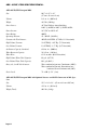
1
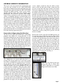
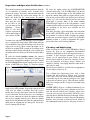
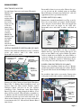
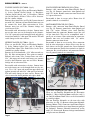
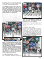
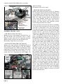
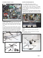
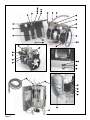
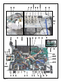
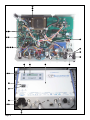
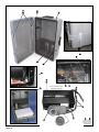
SERVICE MANUAL
& PARTS LIST
AEU-425CF / AEU-425CFH
NSN: 6520-01-508-9583
P.O. Box 1548 • Woodinville, WA 98072-1548
1-800-426-5913 • 425-487-3157 • Fax: 425-487-2608
email: [email protected] • Internet: www.aseptico.com
TABLE OF CONTENTS
General Service Information . . . . . . . . . . . . . . . . . . . . . . . . . . . . . . . . . . . . . . . . . . . . . .1
Inspection & Verification . . . . . . . . . . . . . . . . . . . . . . . . . . . . . . . . . . . . . . . . . . . . . . . . .1
Cleaning & Lubrication . . . . . . . . . . . . . . . . . . . . . . . . . . . . . . . . . . . . . . . . . . . . . . . . . . .2
DIS-ASSEMBLY
Electronics Module . . . . . . . . . . . . . . . . . . . . . . . . . . . . . . . . . . . . . . . . . . . . . . . . . . . . . .3
Optical Handpiece Light Board . . . . . . . . . . . . . . . . . . . . . . . . . . . . . . . . . . . . . . . . . . . .3
Power/Display Board . . . . . . . . . . . . . . . . . . . . . . . . . . . . . . . . . . . . . . . . . . . . . . . . . . . . .3
Power Switch . . . . . . . . . . . . . . . . . . . . . . . . . . . . . . . . . . . . . . . . . . . . . . . . . . . . . . . . . . . .3
Secondary Fuse Holders . . . . . . . . . . . . . . . . . . . . . . . . . . . . . . . . . . . . . . . . . . . . . . . . . .3
Power Cord Receptacle . . . . . . . . . . . . . . . . . . . . . . . . . . . . . . . . . . . . . . . . . . . . . . . . . . .3
Toggle Valves . . . . . . . . . . . . . . . . . . . . . . . . . . . . . . . . . . . . . . . . . . . . . . . . . . . . . . . . . . . .4
Needle Valves . . . . . . . . . . . . . . . . . . . . . . . . . . . . . . . . . . . . . . . . . . . . . . . . . . . . . . . . . . .4
Foot Switch Receptacle . . . . . . . . . . . . . . . . . . . . . . . . . . . . . . . . . . . . . . . . . . . . . . . . . . .4
Motor Receptacle . . . . . . . . . . . . . . . . . . . . . . . . . . . . . . . . . . . . . . . . . . . . . . . . . . . . . . . .4
Two-Way Solenoid . . . . . . . . . . . . . . . . . . . . . . . . . . . . . . . . . . . . . . . . . . . . . . . . . . . . . . .4
Scaler/Motor Toggle Switch . . . . . . . . . . . . . . . . . . . . . . . . . . . . . . . . . . . . . . . . . . . . . . . .5
Scaler Tube and Handpiece . . . . . . . . . . . . . . . . . . . . . . . . . . . . . . . . . . . . . . . . . . . . . . . .5
Scaler Potentiometer . . . . . . . . . . . . . . . . . . . . . . . . . . . . . . . . . . . . . . . . . . . . . . . . . . . . .5
Scaler Module . . . . . . . . . . . . . . . . . . . . . . . . . . . . . . . . . . . . . . . . . . . . . . . . . . . . . . . . . . .5
Three-Way Solenoid . . . . . . . . . . . . . . . . . . . . . . . . . . . . . . . . . . . . . . . . . . . . . . . . . . . . . .6
Fan and Compressor Cover . . . . . . . . . . . . . . . . . . . . . . . . . . . . . . . . . . . . . . . . . . . . . . . .6
Compressor Motor . . . . . . . . . . . . . . . . . . . . . . . . . . . . . . . . . . . . . . . . . . . . . . . . . . . . . . .6
Capacitor . . . . . . . . . . . . . . . . . . . . . . . . . . . . . . . . . . . . . . . . . . . . . . . . . . . . . . . . . . . . . . .7
Flow Block . . . . . . . . . . . . . . . . . . . . . . . . . . . . . . . . . . . . . . . . . . . . . . . . . . . . . . . . . . . . .7
Syringe Air Filter . . . . . . . . . . . . . . . . . . . . . . . . . . . . . . . . . . . . . . . . . . . . . . . . . . . . . . . .7
Three-Way Air Solenoid . . . . . . . . . . . . . . . . . . . . . . . . . . . . . . . . . . . . . . . . . . . . . . . . . .7
Air Pilot Valve . . . . . . . . . . . . . . . . . . . . . . . . . . . . . . . . . . . . . . . . . . . . . . . . . . . . . . . . . .8
Saliva Ejector Pump . . . . . . . . . . . . . . . . . . . . . . . . . . . . . . . . . . . . . . . . . . . . . . . . . . . . . .8
Pressure Sensor . . . . . . . . . . . . . . . . . . . . . . . . . . . . . . . . . . . . . . . . . . . . . . . . . . . . . . . . .8
Syringe . . . . . . . . . . . . . . . . . . . . . . . . . . . . . . . . . . . . . . . . . . . . . . . . . . . . . . . . . . . . . . . . .9
Waste Container Modules . . . . . . . . . . . . . . . . . . . . . . . . . . . . . . . . . . . . . . . . . . . . . . . . .9
Parts List . . . . . . . . . . . . . . . . . . . . . . . . . . . . . . . . . . . . . . . . . . . . . . . . . . . . . . . . . . . . . . .10 - 21
Specifications . . . . . . . . . . . . . . . . . . . . . . . . . . . . . . . . . . . . . . . . . . . . . . . . . . . . . . . . . . .22
Page i
P.O. Box 1548 * Woodinville, WA 98072-1548
1-800-426-5913 * 425-487-3157 * Fax: 425-487-2608
email: [email protected] * Internet: www.aseptico.com
Printed In The USA
GENERAL SERVICE INFORMATION
This service and parts manual offers information and
parts lists not available in the AEU-425CF/CFH
Operation and Maintenance Instruction Manual. It will
help you better understand how the AEU-425CF/CFH
Transport II MDS portable dental system works,
thereby reducing service time. Parts drawings, parts
photographs, and schematic diagrams show components in their actual places in the unit relative to one
another. A plumbing schematic is provided with water
lines indicated in blue. Plumbing parts are called out by
Aseptico part number in the assembly drawings. An
electrical schematic is provided with wires color coded.
Electrical parts are called out by Aseptico part number
in the assembly drawings. Parts, with photo callouts, are
listed in the Parts List. Parts marked “commercially
available” are those items that can be purchased at
retail hardware stores, and minimize service delays
when obtained locally. Use the information in the Parts
List when ordering replacement parts.
Inspection & Operation Verification
To verify that the AEU-425CF/CFH unit is functioning
properly, first follow the set-up procedure in the
Operation & Maintenance manual. Note that connectors
from the waste tank must be connected to the underside
of the plumbing chassis in order for the compressor
motor to turn on. The high vacuum hose is placed in the
toggle holder with the yellow dot and the saliva ejector
vacuum hose is placed in the toggle holder with the red
dot (see Fig. 1). The reason for this is that the unit is
operated by a single dual headed compressor.
Figure 1
Yellow
Dot
create a higher vacuum by using the outlet to draw
more air thru the inlet and creating an open head to
prevent vacuum lock. The high vacuum is electrically
tied to the compressor thru the relay. If the system is
pressurized and the high vacuum hose is removed from
the holder and the toggle on the holder is in the ON
position, the compressor will turn on and air from the
pressure side will vent to the atmosphere. The saliva
ejector works from the pressure side of the compressor
thru an air toggle switch with the red dot (Fig. 1) and an
air pilot and vacuum pump. When the saliva ejector is
removed from it’s holder with the toggle on the holder
in the ON position, the air pilot is activated allowing air
to flow to the vacuum pump. When the saliva ejector is
on, the pressure gauge will cycle as the air pressure
drops until the pressure sensor turns the compressor on
and reaches a pressure of 50 PSI. If the high vacuum is
on at the same time, the compressor motor will run
continuously and the cycling of the pressure side will
not be as audible.
To check the system, verify that unit holds pressure on
the pressure gauge and that the pressure toggle switch
is in the ON position. Note that when the unit is first
turned on, the unit will charge two to three times before
pressure is stabilized. If the unit fails to stabilize, or
turns on within a few seconds, then an air or water leak
is present. Inspect the unit for air or water leaks. It is
best to detect air leaks with a tube or a stethoscope. To
check the three way syringe, depress the air and water
buttons individually and the buttons together for spray.
Spray may be adjusted with the syringe water and air
adjustment screws in the underside of the plumbing
chassis on the left side of the unit (Fig. 2).
Figure 2
Red Dot
Adjustment Screws
The compressor is set up to work one head as a
pressure side and the other head as the high vacuum
side. This is accomplished by using a three way solenoid
on the pressure side in conjunction with a pressure
switch and relay. The three way solenoid allows for air
from the pressure side to be distributed to the air
canister or to the atmosphere. When the power switch
is turned on, the pressure switch will activate the relay
and start the compressor motor. The compressor motor
will turn on and the pressure gauge will start to climb to
50 PSI in a few seconds. The delay prevents stalling of
the compressor and is shorter once the unit is pressurized. When ever the compressor motor is on, the high
vacuum tube will be on. Stalling of the compressor on
the vacuum side is prevented by using a vacuum pump
plumbed to the input and the output of the head to
Figure 3
Inspect the water filter on the water
pick-up tube (Fig. 3). Water filter
requires replacement if it becomes
clogged and restricts water flow.
Water
Filter
Page 1
Inspection and Operation Verification The system has two ways of removing moisture from the
air. A removable air chamber and a drainable filter
prior to the syringe. To remove condensation from the
air bottle, discharge the system and remove the air
bottle and shake out the condensation. To remove
moisture from the Figure 4
Air Filter
filter, open the valve
Drain
Valve
on the filter in the
rear left corner of the
plumbing
chassis
(Fig. 4). Air filter
requires replacement
if it becomes clogged
and restricts air flow.
Vacuum waste container lids should be sealed and holding a vacuum when in operation. HVE solids collector
screen should be inspected for blockage and cleaned or
replaced if necessary. Waste sensor operation can be
checked by turning HVE vacuum on and tilting waste
containers upside down individually and verifying that
the motor turns off and waste full indicator light comes
on.
To verify the electric handpiece motor, first connect
motor to motor receptacle and connect a handpiece to
motor. Place a bit into the handpiece and secure. Switch
the SCALER/MOTOR selector switch on the electrical
chassis to MOTOR (see Figure 5). Turn the coolant
Figure 5
To verify the scaler, switch the SCALER/MOTOR
selector switch (Fig. 5) to SCALER. With a tip on the
scaler, turn the coolant toggle to the ON position and
open the coolant flow prior to stepping on the pedal.
Step on the pedal and place the tip on a piece of metal
(penny, etc.) and verify that fluid is present and a high
pitch noise is present. Note: If the motor coolant
ON/OFF toggle switch is in the ON position, a small
amount of water will be present at the handpiece due to
the switching of the three way solenoid for the
motor/scaler.
The above describes a basic inspection and verification
of the AEU-425CF/CFH system. If the unit still does
not perform as required, further diagnosis of components in the system may require service Use the Trouble
Shooting section as a guide to symptoms and appropriate procedures to fix various problems.
Cleaning and Lubrication
When servicing the AEU-425CF/CFH Military Dental
System, the parts of any component disassembled
should be thoroughly cleaned and inspected before reassembly. A hot detergent solution is an effective
cleaner on all non-electrical parts. Flush all nonelectrical parts with clear, hot water. Abrasive cleaners
have the potential to damage surface finishes and
should be avoided. Any wiping should be done with a
soft, lint free cloth.
Electrical parts should be cleaned with an appropriate
electrical parts cleaner or air.
Selector Switch
toggle to the OFF position. Step on the foot pedal and
verify that the motor is running. Press the reverse
button and verify that the buzzer is on and the drill has
reversed direction. To check for water, use a handpiece
with a water connector or check the motor to confirm
that water is coming from the stem. Turn the coolant
toggle to the ON position and adjust the coolant flow to
open prior to stepping on the foot pedal. Verify that
water is coming out the tube.
Page 2
Cont’d
Use a silicone base lubricating grease, such as Dow
Corning No. 103 to lubricate O-rings, oral evacuator
valves, and seals in the system. Before performing any
reassembly of parts that contain O-rings or seals, apply
a light coat of silicone grease. This will make installation easier and prevent the O-rings or seals from being
damaged.
WATER LINES - Prepare a 1:10 bleach solution (1 part
household bleach to 9 part water). Remove water reservoir and discard residual water. Replace empty water
reservoir and air purge all waterlines. Fill water reservoir with bleach solution. Run bleach through all lines.
Allow bleach solution to stand in lines for 10 minutes.
Remove water reservoir and discard bleach. Flush all
lines thoroughly with clean water. Air purge and leave t
DISASSEMBLY
ELECTRONICS MODULE:
Lay unit down. Open cover and remove Electronics
Module’s six
Figure 6
mounting
screws and
Electronics Module
washers with a
#2 Phillips
head screwdriver (see Fig.
6). To clear
power plug
and fuse holders when
removing
Module, lift
Mounting
Hardware
Module’s right
(6 places)
side slightly,
then slide
Module
towards the
right and remove.
Reassembly is done in reverse order. Ensure that spacers are present on #4 standoffs prior to installing
Board. Reconnect all connectors. Install 1/16” cable ties
approximately where previously installed.
OPTICAL HANDPIECE LIGHT BOARD (PN 330407):
Remove cable connector on Board (see Fig. 7). Remove
screws and washers with 1/16 Allen wrench.
Reassemble in reverse order.
SECONDARY FUSE HOLDERS (PN 830090 - 2 Qty):
De-solder wires from Holder (see Fig. 9). Remove
Holder with 9/16” open-end wrench. Take Spacer and
place on new Holder and replace Holder. Re-solder
and heat shrink wires on Holder (use other Holder as
reference). Ensure that sufficient gap between power
connector and Holder terminal is maintained to prevent arcing. Place one 0.63 Amp fuse in each Holder.
Figure 7
Power/Display Board
Transformer
Cable Tie
w/Holder
Optical Handpiece
Cable Connector
Light Board
Mounting Hardware
& Standoff (x4)
Optical
Handpiece
Light Board
Power/
Display
Board
POWER SWITCH (PN 830018):
Remove wire terminals from Switch (see Figs. 8a & 8b).
Press tabs in on Switch and remove Switch. Remove
cover and place on new Switch. Place new Switch into
chassis with circle on toggle to the OFF side.
Reassemble wires with white to white, and black to
black.
Figure 8a
Figure 8b
Wire
Terminals
(4)
Off / ’O’
Position
Power
Switch
POWER CORD RECEPTACLE (PN 840067):
Remove wires from Power Switch (see Fig. 9). Remove
ground from ground terminal with 5/16” socket. Remove
receptacle from chassis with #1 Phillips head screwdriver.
Re-assembly is done in the reverse order. Connect wires
to the power switch white to white, and black to black.
Figure 9
POWER/DISPLAY BOARD (PN 330350):
Remove the Cable Connector from Optical Handpiece
Board (Fig. 7). Remove Board mounting screws and
washers with 1/16 Allen wrench. Remove Optical
Handpiece Board and place to the side. Remove
remaining Cable Connectors from Power/Display
Board. Clip cable tie going through the holders. Leave
other cable ties in place. This will make reassembly easier. Remove the four standoffs on Board with 1/4” socket. Remove the four cap screws and washers with 1/16”
Allen wrench. Remove the four cap screws and washers
in transformer with 5/32” Allen wrench. Remove Board
from chassis.
Switch
Cover
Power Switch
Power Cord
Receptacle
Heat Shrink
Ground
Terminal
Secondary
Fuse
Holder (2)
Fuse Holder
Spacer
Page 3
DISASSEMBLY
- Cont’d
TOGGLE VALVES (PN 730010 - Qty 3):
There are three Toggle Valves on Electronics Module:
1.) Scaler Coolant On/Off Switch; 2.) Handpiece
Coolant On/Off Switch; and, 3.) Handpiece Coolant
Air On/Off Switch. All three Valves can be disassembled in a similar fashion.
Remove tubes from Valve (see Fig. 10). Loosen internal
nut with 9/16” thin box-end wrench until outer nut can
be removed by hand. Note orientation of Valve.
Remove outer nut and Valve. Remove fittings and
attach to new Valve.
Reassemble with orientation as before. Loosen inner
nut so that outer nut can be brought to the chamfer.
Use 9/16” open-end wrench on upper body and tighten
internal nut with 9/16” thin open-end wrench. This will
avoid damage to the outer surface.
NEEDLE VALVES (PN 730066 - Qty 2):
There are two Needle Valves on Electronics Module:
1.) Scaler Coolant Adjust Valve; and, 2.) Handpiece
Coolant Flow Adjust Valve. Both Valves can be disassembled in a similar fashion.
Remove the Valve knob with a 1/16” Allen wrench (see
Fig. 10). Note orientation of Valve prior to removal.
Remove tubes from Valve. Loosen inner nut with a
9/16” thin open-end wrench until outer nut removes
freely by hand. Remove outer nut and Valve. Remove
fittings and attach to new Valve.
Reassembly with orientation as before. Loosen inner
nut so that outer nut can be brought flush to valve surface. Use a 9/16” open-end wrench on upper body and
tighten internal nut with 9/16” thin open-end wrench.
This will avoid damage to outer surface. Ensure that
valve is turned to closed position and replace knob.
FOOT SWITCH RECEPTACLE (PN 875026):
Remove cable connector from Power/Display Board
(see Fig. 11). Remove ground wire from ground stud
with 5/16” socket. Remove connector from chassis with
3/4” open end wrench.
Reassembly is done in reverse order. Ensure that all
ground terminals are reinstalled.
MOTOR RECEPTACLE (PN 875048):
Remove cable connector from Power/Display Board
(see Fig. 11). Remove ground wire from ground stud
with 5/16” socket. Remove wires from Two-Way
Solenoid from the connector. Remove water line and
air line from barb. This can be accomplished with a
small pair of scissors. Note orientation of connector.
Remove four nuts and washers with 1/4” socket.
Remove connector from chassis.
Reassembly is done in reverse order. Place connector
back in same orientation as before. Place water line to
barb closest to Grn/Yel ground wire. Insert Solenoid
wires into connector. Ensure that terminals are firmly in
connector. Re-attach hardware and connector. Ensure
that all ground terminals are reinstalled.
Figure 11
Foot Switch
Cable
Connector
Fitting
Figure 10
Fittings
Two-Way
Solenoid
(Water)
Inner
Nut
Motor
Receptacle
Needle Valve
(x2)
Page 4
Needle Valve
Knob
Outer
Nut
Toggle Valve
(x3)
Motor Receptacle
Cable Connector
Foot Switch
Receptacle
Ground
Stud
TWO-WAY SOLENOID (PN 730469 - Qty 2):
There are two Two-Way Solenoids on the Electronics
Module: 1.) Water On/Off to Motor and Scaler; and, 2.)
Air On/Off to Motor. Both Valves can be disassembled
in a similar fashion.
The two Two-Way Solenoids are the two valves with
blue wires (see Fig. 11). Remove tubing from Solenoid.
Remove Motor Cable Connector from Power/Display
Board. Remove two blue wires from Connector going to
the Solenoid. Remove Solenoid button-head screws
with 1/16" allen wrench. Remove fittings from Solenoid
and place on new Solenoid.
Re-assembly is done in the reverse order. Note: Ensure
that the common-marked side of water Solenoid is connected to line coming from Plumbing Module.
Figure 13
Scaler Assy
SCALER/MOTOR TOGGLE SWITCH (PN 875041):
Remove Toggle Switch 10-pin cable connector from
Power/Display Board (see Fig. 12). Remove the red and
black wires coming from Three-Way Solenoid. Remove
the two brown wires coming from Scaler. Locate and
cut the violet and black wires from Toggle Switch.
Remove Switch with 3/16" box-end wrench.
Reassemble in the reverse order. Place red wire from
Three-Way Solenoid into pin 7 of cable connector.
Place brown wire with fuse from the Scaler into pin 8.
Place black wire from Solenoid into pin 9 and remaining brown wire from Scaler into pin 10. Ensure that the
wires are secure in cable connector. Solder and heat
shrink violet and black wires back together. Reinstall
cable connector into Power/Display Board.
Figure 12
Scaler
Assy
Toggle
Black
Switch
Wire
10-Pin Cable
Connector
Violet
Wire
Scaler/
Motor
Toggle
Switch
Brown Three-Way
Wires Solenoid
Black
&
White
Wires
Scaler
Tube
Cable Scaler Scaler
Scaler
Tie Potentio- Binding Coolant
meter
String Adjustment
Valve
wiring going to the cable connector in Scaler Assembly
(see Fig. 13). De-solder orange, red and brown wires
coming from Scaler to Potentiometer. Remove
Potentiometer with a ½" box-end wrench.
Reassemble in the reverse order. Trim tab off
Potentiometer prior to reinstalling. Re-solder and heat
shrink wires according to sketch. Also refer to electrical
schematics.
SCALER MODULE (PN 730500):
Disconnect the wires from Power Receptacle to Power
Switch (see Fig. 14). Disconnect cable connectors from
Secondary Fuses to the Power/Display Board. Slide
cover back from Scaler and remove connector. Remove
nuts and washers holding down the Scaler plate with
5/16" socket. Turn plate upside down and remove screws
with #1 Phillips head screwdriver. Remove the module.
Reassembly is done in the reverse order.
Figure
SCALER TUBE AND HANDPIECE (PN 730500):
Remove Scaler Tube from fitting on Scaler Coolant
Adjustment Valve (see Fig. 13). Cut black and white
wire coming from Tube. Remove cable tie and binding
string. Pull Tube out thru chassis hole.
Scaler Mtg
Hdwre
Reassemble in the reverse order. After Tube has been
inserted thru chassis hole, install cable tie around Tube
just above the grommet in chassis and tie off binding
string around Scaler Coolant Adjustment Valve. Trim
Tube and wires to fit. Re-attach Tube to fitting on
Adjustment Valve, and solder and heat shrink the wires.
Fill Tube with RTV to prevent pull out.
SCALER POTENTIOMETER (PN 810164):
Make a sketch of the Potentiometer orientation and
Secondary
Fuses
Cable
Connectors
Scaler
Assembly
w/Plate
Secondary Power
Power
Fuse (x2) Switch Receptacle
Page 5
DISASSEMBLY - Cont’d
THREE-WAY SOLENOID (PN 730474):
Note the orientation of Three-Way Solenoid on Scaler
plate (see Fig. 15). Remove tubing at Three-Way
Solenoid. Remove Motor/Scaler cable connector on
Power/ Display Board. Remove red and black wires
coming from Solenoid. Remove nuts holding Scaler
plate with 5/16" socket. Remove Power and Fuse cable
connectors from Power/Display Board. Elevate the
plate to access the screws to Solenoid. Remove screw
with #1 Phillips head screwdriver. Remove fittings and
place on new valve.
Reassemble in the reverse order. Orientate Three-Way
Solenoid Valve so tube coming from Two-Way Solenoid
goes to fitting marked COM (common) on Three-Way
Solenoid. The fitting on top of Three-Way Solenoid
goes to Motor coolant On/Off Toggle Valve, and fitting
marked NC goes to Scaler coolant On/Off Toggle Valve.
Figure 15
Motor
Coolant
On/Off
Toggle
Valve
Power
& Fuse
Cable
Conn.
Two
Three
Way
Way
Solenoid Solenoid
Scaler
Coolant
On/Off
Toggle
Valve
MOTOR MODULE:
• FAN & COMPRESSOR COVER
Lay unit on its back and remove all containers (see Fig.
16). Remove Filter from Compressor Motor with channel locks. Remove the seven Cover-mounting screws
and washers with #2 Phillips-head screwdriver. Move
Cover up and out to expose wires. Disconnect power
cable connectors to Fan and remove ground wire at
Motor. Remove Cover from Case. Note orientation of
Fan. Remove Fan fasteners with #1 Phillips-head
screwdriver and 5/16” socket.
Reassemble in the reverse order. Take care when reinstalling Cover that tubing from Compressor is not
kinked.
Page 6
Fan
Cover
Fan
Fasteners
Fan
Guard
Fan
Power
Connectors
Ground
Wire
Filter
Power/DisplayBoard
Motor/
Scaler
Cable
Conn.
Figure 16
• COMPRESSOR MOTOR (PN 730503):
Remove Filter and Compressor Cover as previously
described in FAN DISASSEMBLY. Remove rubber
feet on bottom of unit case to expose screws (see Fig.
17). Remove the four mounting screws with #3 Phillipshead screwdriver. Remove cable-tie holding down wires
on Motor. Remove ground wire with #2 screwdriver.
Cut wires at heatshrink to Motor. Lift Motor 90º and
remove pressure tube by removing clamp. (Note: Clamp
can be removed by sliding tabs sidways. Removal of
Tube is easier if heated slightly with heatshrink gun.)
Lift Motor from Case. Note orientation of fittings. Most
tubes can be left attached if not damaged. Remove
Venturi from large tube in center of Motor by pulling on
Venturi. Use adjustable 6” wrench to remove fitting and
place in new Motor. Push Venturi back into large tube
in middle of Motor. Remove feet and attach in same
orientation on new Motor.
Reassembly is done in the reverse order. Position Motor
in Case. Ensure that tubing is not kinked. Reattach
pressure hose with clamp (use pliers to tighten clamp).
Align Motor and mount to bottom of Case with screws
and countersunk nylon washers. Note, to level unit,
screws and nylon washers are used on front side, while
flat washers are added on back side only. Attach new
rubber feet. Attach ground wire to Motor. Solder and
heatshrink wires. Note that yellow goes to orange, and
two brown wires are attached to black and red wires
with blue bands. Use 6” wire tie to attach wires to tie
mount. Assemble Motor Cover and Filter as described
previously in FAN section.
Pressure
Tube
Clamp
Figure 17
Filter
Figure 18
Syringe
Air Filter
(under
plate)
Filter
Hoses
Syringe
Filter
Plate
Water
Line
Pressure
Tube
Capacitor
Tie
Wrap
Plumbing
Chassis
Mtg Screws
(Under rubber feet)
Flat
Washer
(for
Leveling)
Venturi
Center
Tube
Fitting
PLUMBING CHASSIS:
Lay unit on its back and remove all containers (see Fig.
18). Remove the three Plumbing Chassis mounting
screws and washers with #2 Phillips-head screwdriver.
Carefully lower Plumbing Chassis from top of Case and
turn over to expose Chassis components (see Fig. 18).
• CAPACITOR (Part of Compressor Motor Assy):
De-solder wires from Capacitor (see Fig. 18). Remove
tube from Filter to Flow Block. Remove Capacitor
mounting nut with 11/32" socket.
Reassemble in the reverse order. Re-solder wires to
Capacitor terminals (wires have no orientation) and
heat shrink. Heat shrink and seal (with RTV) rear terminals on Capacitor. Replace tube on Flow Block.
• FLOW BLOCK (PN 460546):
Remove tubes from Flow Block (see Fig. 18). (Note:
Removal of tubes is easier if heated slightly with heat
shrink gun.) Remove Block mounting screw on bottom
of Plumbing Chassis with 1/16" Allen wrench.
Reassembly is done in the reverse order. Remove fittings from old Block and attach to new Block. Note
that ribbed line coming from Syringe is designated for
water. Attach this line to water fitting on Block which is
indicated by water symbol on Chassis front panel.
Flow
Block
• SYRINGE AIR FILTER (PN 730495):
Remove the two tubes going to Filter (see Fig. 18).
(Note: Removal of tubes is easier if heated slightly with
heat shrink gun.) With 3/32" Allen wrench, remove two
mounting screws that attach Filter plate to standoffs.
Remove plate and fittings from Filter.
Reassemble in the reverse order. It is suggested that
Lex 8 lubricant/seal (P/N 490061) be applied to fitting
to prevent leakage.
• THREE-WAY AIR SOLENOID (PN 730454):
Remove the screws holding the Saliva Ejector Pump.
Remove snap clamp from tube coming from
Compressor (see Fig. 19). Remove snap clamp from
tube coming from Air Reservoir. Disconnect wires to
Solenoid. Remove the two tubes going to Solenoid.
(Note: Removal of tubes is easier if heated slightly with
heat shrink gun.) Remove Solenoid mounting nuts and
washers with 11/32" socket. Remove tube from Air
Reservoir to Syringe Air Filter. Remove tie wraps from
both Solenoid Air Filters and remove Filters. Remove
the Air Solenoid Valve from Plumbing Chassis. Note
orientation of fittings. Remove fittings from Air
Solenoid Valve and attach to new Valve.
Reassemble in the reverse order. Inspect Air Filters and
replace if dirty/clogged. Cut the two wires from Solenoid
to approximately 4". Solder one diode (P/N 880030) onto
1" piece of violet wire (22 gauge - stranded) to cathode
(bar side) of diode. Solder 4" piece of violet wire (22
gauge - stranded) to other side of 1” wire. Twist 1" wire
side to one wire from Solenoid and heat shrink over
diode. Twist other wire from Solenoid to 4" wire and
Page 7
crimp on terminals (P/N 860102) when reattaching.
Figure 19
Solenoid
Air Filter
Air Reservoir
Tube
Three-Way
Air Solenoid
Compressor Tube
Snap Clamp
Violet Wire
w/Diode
Compressor Tube
Solenoid
Mtg Hardware
(Air Filters not shown)
Air Reservoir
Snap Clamp
PLUMBING CHASSIS - Cont’d
• AIR PILOT VALVE (PN 730264):
Remove the three tubes going to Air Pilot Valve (see
Fig. 20). Remove nuts and washers with ¼" socket.
Remove bracket with two 9/16" open-end wrenches.
Remove fittings and place on new Air Pilot Valve.
Reassembly is done in the reverse order.
• SALIVA EJECTOR PUMP (PN 730348-08):
Remove tube from underside of Plumbing Chassis to
Saliva Ejector Vacuum Pump (see Fig. 20). Remove
Vacuum Pump with 3/32” Allen wrench. Remove fitting
from Pump. Attach fittings to new Pump. Note orientation of plastic elbow. To prevent leakage, it is suggested that Lex 8 lubricant/seal (P/N 490061) be
Figure 20
Saliva
Ejector
Vacuum
Pump
Plastic
Elbow
Air Pilot
Valve
Pilot
Valve
Bracket
Relay
Vacuum Pump
Tube Fitting
Vacuum Pump
Tube (under Chassis)
Page 8
applied to fittings.
Reassemble in the reverse order.
• PRESSURE SENSOR (PN830067):
Remove tube to Pressure Sensor (see Fig. 21). Remove
wire connectors going to Pressure Sensor. Remove two
screws holding wires from Pressure Sensor to Relay.
Cut blue wire from wire harness close to ring terminal.
With 3/32" Allen wrench, remove two button-head
screws under Plumbing Chassis that attach pressure
bracket. Remove Pressure Sensor from Chassis.
Remove nut from Sensor with adjustable wrench.
Attach fitting to new Pressure Sensor.
Prepare new Pressure Sensor first when reassembling:
Cut red wire flush to Sensor (red wire not used). Cut
green wire 4" from Sensor. Cut 4" piece of remaining
green wire and attach to green wire from Sensor with
terminal (P/N 860102). Attach terminal (P/N 860101)
to other end of 4” green wire. Cut black wire from
Sensor to 2.5" and solder to anode (not the bar end) of
a diode (P/N 880030). Cut 2.5" piece of yellow wire (22
gauge - stranded) and solder to same end. Attach terminal (P/N 860102) to yellow wire. Cut two 2.5" pieces
of yellow wire (22 gauge - stranded) and solder to cathode (bar side) of wire. Heat shrink diode and solder
joints. Attach terminal (P/N 860101) to one of yellow
wires. Cut ¾" piece of blue wire (22 gauge-stranded)
and solder to cathode (bar side) on a diode (P/N
880030). Cut 3" piece of blue wire (22 gauge-stranded)
and solder to other side of diode. Twist short end of
blue wire cathode (bar side) of diode and remaining
yellow wire together. Heat shrink over diode. Attach
ring terminal (P/N 860004) to cathode (bar side).
Attach Pressure Sensor to bracket and reinstall tubing
and connectors. Note: Refer to electrical schematic for
electrical connections. It is best not to attach bracket to
the Plumbing Chassis prior to setting pressure. Twist
remaining blue wire with blue wire coming from cable
assembly and attach ring terminal (P/N 860004).
Remove setscrew from back of Pressure Sensor and
install Air and Water Bottles into their holders on
Chassis. Plug AEU-425CF/CFH System into power
source and turn the Pressure Sensor setscrew clockwise
until pressure gauge located on front of Plumbing
Chassis reads 50 P.S.I. Replace setscrew and attach
Pressure Sensor/bracket.
PLUMBING CHASSIS - Cont’d
WASTE CONTAINER MODULES
Figure 21
Sensor
Tube Fitting
Tube to
Pressure
Sensor
Relay
Blue
Wire
Sensor
Mtg Nut
Saliva and High Volume Waste Container
FLOAT SENSOR CONNECTOR (PN 860080):
Disassemble Float Sensor Connectors by trimming
back heat shrink and cutting wires to Connectors (see
Fig. 23a). Remove nuts that hold Connectors to
Plumbing Chassis.
To reassemble, place Float Sensor Connector through
Plumbing Chassis. Apply RTV to Connector to avoid
leakage. Slide sleeving over wires. Attach nut to Sensor.
Figure 23a
Pressure
Sensor
Diodes
Sensor Bracket
SYRINGE (PN TA-90):
Unscrew handle from Syringe head (see Fig. 22).
Remove tube clamps and tubes from fittings on Syringe
head. Remove tube clamps from tubes and remove
handle.
Reassemble by placing tube through handle and placing tube clamps on tube. Place water tube (designated
by ribbed lines on side of tube) to the water side. Water
side is indicated by water symbol on head. Attach handle to Syringe head and test for air, water, and spray.
Figure 22
Float Sensor
Connectors
WASTE CONTAINER FLOAT SENSOR (PN
730514):
Remove nut (see Fig 23b). Cut wires and remove
Sensor.
To reassemble, resolder new Sensor wire and apply
heat shrink. Reattach nut.
Figure 23b
Container
Lid
Water
Symbol
Head
Baffle
Handle
Float
Sensor
Float Sensor
Connector
Nut
Page 9
1
19
16
20
17
21
(Inside
18
Container)
23
22
15
(Inside
Container)
11
10
12
27
16
28
17
30
(Inside
18
Container)
31
29
15
(Inside
Container)
25
26
33
24
32
4
2
210
3
9
5
6
7
8
37
38
35
36
Page 10
34
13
14
(Note: Item No. 35
Shown on Page 20)
ITEM
DESCRIPTION
PART NO.
Qty
1
1
AEU-425CF FINAL ASSY
120284
1
2
2
LABEL MYLAR AEU-425 WATER
420299
2
3
3
BOTTLE 1LT ROTO-MOLDED HDPE
730471
2
4
4
LABEL MYLAR AEU-425 AIR
420307
1
5
5
FTN 1/4 CLEAR SLEEVE
730042
16
6
6
FILTER 10-32 THREAD STAINLESS
730326
1
7
7
FTN BARB 10-32 X 1/8 BRT/NKL (BINSTOCK)
730073
6
8
8
GASKET NYLON #10
730074
24
9
9
TUBING POLY 1/4OD BLU
AA-95B
0.81 Ft
(BINSTOCK)
(BINSTOCK)
(BINSTOCK)
10
10
FTN QD CPC ELBOW MALE 1/4" BARB
730353
1
11
11
TUBING SALIVA EJECT 3/8OD GRY
AA-86G
5.5 Ft
12
12
VALVE SAL/EJECT AUTOCLAV LEVER
AA-37LA
1
13
13
HOOK 1/4" BLACK PLASTIC
730371
4
14
14
CORD BUNGEE 1/4" DIA.
730370
1.83 Ft
15
15
CABLE DC POWER 2.1mm 24AWG BLK 72 INCHES LONG
870279
2
16
16
NUT FLOAT AEU-425 SENSR RETAIN
461149
2
17
17
O-RING .380ID X .091CS EP70
520028
2
18
18
SENSOR REED FLOAT POLYPROPYLEN INNOVATIVE COMPONENTS
730514
2
19
19
FTN QD FEM 1/4" PNL MNTG MOD
730516-08
1
20
20
GASKET AEU-425 AIR BOTTLE
461011
1
21
21
FTN QD CPC PANEL MNT 1/4" MOD
730352-08
1
22
22
BAFFLE AEU-425 SALIVA BOTTLE
461150
1
23
23
BOTTLE 1 PINT LID AEU-425 MOD
730272-04
1
24
24
FTN QD CPC ELBOW MALE 1/2" BARB
730355
1
25
25
TUBING ASEPSI-FLEX 1/2ID GRY
AA-83A
6.21 Ft
26
26
VALVE CENT VAC UNIV LEVER AUTO
AA-35LA
1
27
27
STRAINER 1/4NPT 20 STAINLESS MESH PVC BASE
730335
1
28
28
FTN QD CPC PANEL MNT FEM 1/2" MOD BARB
730354-08
1
29
29
BAFFLE VACUUM BOTTLE AEU-425
461071
1
30
30
FTN QD FEM 1/2" POLYSULF MODFD PANEL MOUNT MODIFIED
730486-08
1
31
31
BOTTLE 1000mL W/LID MODIFIED AEU-425
460877
1
32
32
FTN QD PLC STRAIGHT MALE 1/4" ACETAL
730515
1
33
33
TUBING 3/8OD X .062W GRY URETH
730374
1.0 Ft
34
34
FILTER BREATHER VENT 1/4-18NPT WITH SCREEN NYLON FILTRATION
730461
1
35
35
TERM FEM .250 X .032 16-14AWG BLUE (BINSTOCK)
860101
13
36
36
CHASSIS AEU-425 MOTOR COVER CMPL
460856-08
1
37
37
M/S STNLS PHDPHL 8-32X3/8
510247
2
38
38
WASHER INT STAR S/S #8
510420
36
TABLE 300028
(BINSTOCK)
(BINSTOCK)
Page 11
40
39
41
48
42
49
43
38
53
52
25
44
65
55
47
58
57
46
45
56
51
63 64
50
54
70
213
59
61
60
66 67
62
69
68
71
74
77
76
78
73
75
72
Page 12
ITEM
DESCRIPTION
PART NO.
Qty
39
39
FAN 24V 23.3CFM 60X60X25mm
540005
1
40
40
M/S STNLS FLAPHL 6-32 X 1.375
510528
4
41
41
NUT HEX 6-32 STNLS
510293
8
42
42
WASHER INT STAR S/S #6
510419
11
43
43
WASHER FLAT STNLS #6
44
44
GUARD FAN 60mm
45
45
TERM MALE .250 X .032 16-14AWG BLUE
860102
10
46
46
FOAM MOTOR COVER FRONT AEU-425
461048
1
47
47
FOAM MOTOR COVER TOP AEU-425
461049
1
48
48
BOLT STNLS HOOK 1/4HOLE8-32THD 1.7" MAX LENGTH .14 WIRE DIM
510486
4
49
49
NUT HEX 8-32 STNLS
50
50
TERM INSUL RING #8 22-16 RED (BINSTOCK)
51
51
52
52
AEU-425
(BINSTOCK)
(BINSTOCK)
510431
730485
(BINSTOCK)
4
1
510428
5
860068
6
WIRE PVC #18 500FT GRN/YEL-300V (BINSTOCK)
870261
1.79 Ft
CLAMP HOSE SNAPPER .616/.707
510425
5
53
53
FTN 1/4NPT X 1/2" BARB
730484
1
54
54
TUBING 1/2OD X .062W GRY URETH
730373
0.21 Ft
55
55
FTN 3/8 HOSE BARB X 1/4NPT 90 DEG ELBOW
730414
1
56
56
TUBING 3/8OD X .245ID GRY POLY 90 DURMETR 250FTREEL
730312
3.5 Ft
57
57
CLAMP HOSE SNAPPER .351/.394
510450
6
58
58
FTN 1/4 HOSE BARB X 1/4MPT 90D ELBOW
730443
2
59
59
FILTER MOTOR VENTURI AEU-425CF
330488
1
60
60
PUMP VACUUM AIR-VAC SINGLE
730348
1
61
61
FTN 1/8 MPT X 3/8 BARB MODIFID
730366-08
1
62
62
FTN 1/4 HOSE BARB 1/8FPT STRT
730498
1
63
63
TIE WRAP 4" PICO WHT,
510137
11
64
64
TIE WRAP MOUNT 1X1 W/ADH BACK (BINSTOCK)
510206
11
65
65
PUMP VACUUM DUAL VOLT
730503
1
66
66
M/S STNLS FLAPHL 1/4-20 X 3/4
510538
4
67
67
WASHER 1/4" NYLON COUNTERSUNK
510527
4
68
68
WASHER USS STNLS 1/4 FLAT
510297
12
69
69
FOOT BUMPER .5 X.14 CYLIN BLK (BINSTOCK)
850008
4
70
70
MOUNT RUBBER 1/2"HX3/4"D W/1/4 -20 STUD AND HOLE
730462
4
71
71
MOTOR/CABLE ASSY W/LIGHT & H2O
AE-200-30
1
72
72
FOOTSWITCH ON/OFF 8 PIN
AE-7P
1
73
73
FTN 1/8ID SLEEVE CLAMP CLEAR (BINSTOCK)
730015
29
74
74
SYRINGE 3-WAY AIR WATER
TA-90
1
75
75
TUBING 2H POLY COIL SYNG GRY
AA-84G
1
76
76
FTN 1/8 DELRIN UNI-CLAMP
730096
10
77
77
FTN BARB 1/16 DELRIN TEE
78
78
TUBING POLY 1/8OD BLU
STAGE
(BINSTOCK)
AEU-425 & ADU-12
3/4OD X 5/16ID, (BINSTOCK)
SUPPLIED WITH NO TUBING
(BINSTOCK)
(BINSTOCK)
730152
2
AA-94B
5.5
Page 13
102
84
106
98
97
96
80
95
79
5
104
107
94
81
114
92 93
116
117 86 38
105
120
101
82
122
112
113
111
115
119
118
121
83
100
84
91
89 90
109
108
110
99
(Note: Capacitor Part of
Vacuum Pump 730503)
49
38
88
85
87
86
38
103
(Note: Item No. 103
Shown on Page 16)
Page 14
ITEM
DESCRIPTION
PART NO.
Qty
79
79
FTN BARB 1/8 X 1/16 X 1/8 TEE
730044
3
80
80
TUBING POLY 1/4ODX.159ID GRY 90 DUROMETER
AA-95G
2.27 Ft
81
81
FTN 1/8 NPT X 1/8 90 DEG. BARB
730302
2
82
82
BLOCK FLOW ADJUSTMENT MODIFIED USE PN 730022
460546
1
83
83
C/S BTNSOC STNLS 4-40X1/4
510016
6
84
84
WASHER SPLIT STNLS #4
510433
18
85
85
FILTER 1/8" NPT 5 MICRON
86
86
C/S BTNSOC STNLS 8-32 X 3/8
87
87
88
88
89
89
HEAT SHRINK 1/8 BLK
90
90
DIODE IN4004 GEN PURP 400V
91
91
WIRE PVC #22 500FT VIO (7)
92
92
93
93
94
94
FTN 1/4 HOSE BARB 1/8MPT MOD
461015
1
95
95
FTN 1/4 HOSE BARB 1/8NPT STRT
730451
1
96
96
VALVE CHECK 100PSI 1/8FPT BRAS
730453
1
97
97
FTN ELBOW 90DEG 1/8 MPT
730432
1
98
98
FTN 1/4 HOSE BARB-1/8MPT
730121
1
99
99
TABLE 300010, (BINSTOCK)
(BINSTOCK)
730495
1
510404
13
STANDOFF 3/8 ROUND X 2-5/8"L X 8-32 THREAD ALUMINUM
510529
2
MOUNT AEU-425 FILTER
460898
1
870118
0.28 Ft
(BINSTOCK)
TABLE 300011 (BINSTOCK)
(BINSTOCK)
880030
3
870049
3.08 Ft
FILTER SOLENOID RELIEF AEU-425CF
330490
1
MUFFLER/FILTER SINTERD BRNZ
730450
1
1007-22730-7 (BINSTOCK)
VALVE AIR 3 WAY 2POS 1/8FPT
1/8 MPT
IN-LINE
730454
1
(BINSTOCK)
AA-94C
6.03 Ft
100
100
TUBING POLY 1/8OD CLR
101
101
BRKT 90DEG X 31/64" DIA MNTNG
730245
1
102
102
NUT HEX 4-40 STNLS
510434
10
103
103
SPACER NYL 4-40X5/8LX1/4OD
510478
4
104
104
WASHER FLAT STNLS #4
510192
6
105
105
VALVE AIR PILOT 2WAY W/O EX NO
730264
1
106
106
FILTER SALIVA VENTURI AEU-425CF
330489
1
107
107
FTN BARB 10-32 X 1/8 90D ELBOW (BINSTOCK)
730023
2
108
108
FTN 1/8MPT X 1/4 DOUBLE BARB
730345
1
(BINSTOCK)
HEX
(BINSTOCK)
109
109
VACUUM PUMP SINGLE STAGE
730348-08
1
110
110
STANDOFF M/F #8 X 0.75
510602
2
111
111
TERM INSUL RING #6 22-16
860004
4
112
112
WIRE PVC #22 1000FT YEL (4)
1007-22730-4 (BINSTOCK)
870046
3.29 Ft
113
113
WIRE PVC #22 1000FT BLU (6)
1007-22730-6 (BINSTOCK)
870048
7.5
114
114
FTN REDCR COUPLNG 1/4FPT TO10- 32-UNF-2B BRASS HEX
730459
1
115
115
SWITCH PRESR10-100PSI 12/24VDC AEU-425
830067
1
116
116
NUT LOCK 1/4 NPSL
730430
1
117
117
BRKT AEU-425 PRESSURE
460900
1
118
118
HEAT SHRINK 3/32 BLK
870116
0.08 Ft
1007-22730-3 (BINSTOCK)
870045
3.42 Ft
1007-22730-8 (BINSTOCK)
870050
3.0 Ft
(BINSTOCK)
AEU-425
119
119
WIRE PVC #22 1000FT ORN (3)
120
120
WIRE PVC #22 500FT GRY (8)
121
121
CONN JACK 2.1MM RND PLASTIC
122
122
RELAY 24VDC 280VAC 25 AMPS
BLK CHASSIS/PANEL MOUNT
860080
2
800084
1
Page 15
137
132
86
138
123
124
134
135
84
136
142
130
38
131
126
86 38
139
129
128
83
127
141
140
143
144
125
167
133
86
148
84
38
83
149
150
146
145
103
84
104
151
168 169
164 41 42
161 162 163
157 76 8
147
170 83 84
152
166
171
172
153
165
154
155
158
159
Page 16
156
160
ITEM
DESCRIPTION
PART NO.
Qty
123
123
124
124
VALVE CHECK AIR ANTI RETRACTIN AEU-425
730428
1
125
125
REGULATOR 35 PSI MINI FIXD
730521
2
VALVE TOGGLE 3W/2P GRY W/EX
730014
1
126
126
GASKET FOR NWS-8 BOTTLE LID
730473
2
127
127
CAP AIR BOTTLE 1 LITER AEU-425
461420
1
128
128
CHASSIS BOTTLE AEU-425
461422
1
129
129
FTN BARB 10-32 X 1/16 PLATED (BINSTOCK)
730062
18
130
130
GAUGE PRESSURE 100 PSI 10/32
730550
1
131
131
CAP WATER/GAUGE AEU-425
461421
1
132
132
BRACKET WATER AEU-425 CMPL
461419-08
1
133
133
BEZEL LED T 1-3/4 ONE PCE BLK (BINSTOCK)
850013
1
134
134
HOLDER 1/2D UNIVERSAL GRY
AA-68G
2
135
135
HOLDER ELECTRIC AUTOMATIC W/ LOCKOUT TOGGLE GRAY
730417
1
136
136
HOLDER AUTO W/LOCKOUT HPCE GRY
AA-59G
1
137
137
HOLDER BAR 1/2D QUAD GRY
AA-67Q
1
138
138
M/S STNLS PHDPHL 4-40X1/2
510191
2
139
139
CHASSIS AEU-425 PLUMBING CMPL TRANSPORT II DENTAL
460857-08
1
140
140
HEAT SHRINK 3/8 BLK
870117
0.5 Ft
141
141
CABLE 4 COND #18 BLK
870251
12.42 Ft
142
142
LED T 1-3/4 RED
143
143
CLAMP CABLE NYLON 5/16 DIA W/ .203 MNTG HOLE WHITE
144
144
HEAT SHRINK 1/8" YELLOW
870254
0.5
145
145
WIRE PVC #22 1000FT BRN (1)
1007-22730-1 (BINSTOCK)
870043
3.0 Ft
146
146
WIRE PVC #22 1000FT WHT (9)
1007-22730-9 (BINSTOCK)
870051
3.0 Ft
147
147
CONN .1 HSNG LOCK/PL 7 PIN
860137
1
148
148
TUBING SILICONE .281IDX.375OD 70 DURO GRAY
730489
2.0 Ft
149
149
WIRE PVC #22 1000FT RED (2)
870044
4.58 Ft
150
150
CONN .1 TERM CRIMP LOOSE 22-30 (BINSTOCK)
860023
11
151
151
CONN .1 HSNG LOCK/POL 2 PIN
860076
4
152
152
KNOB GRY PLASTIC 1/4D STYLE II
850012
1
153
153
WIRE ASSY AEU-425 SWITCH SCALR WITH FIBER OPTICS
875041
1
154
154
RES POT LIN 100K PCB TERM (90D) (PART OF ASC-10 SCALER ASSY)
810164
1
155
155
WASHER NYL .505IDX.750ODX.062T (BINSTOCK)
510175
3
156
156
VALVE NEEDLE CONTROL W/O KNOB
730066
2
157
157
FTN ELBOW 90 10-32 X 1/16BARB WHITE NYLON
730011
1
158
158
VALVE 3 WAY SOLENOID 24V
730474
1
159
159
M/S STNLS FLAPHL 4-40X3/8
510112
2
160
160
VALVE TOGGLE 2W/2P GRY W/O EX
730010
3
161
161
SCALER ASSEMBLY SYSTEM
ASC-10
1
162
162
M/S STNLS FLAPHL M3 X 6mm
510530
2
163
163
SCALER ASSEMBLY SYSTEM
730500
1
164
164
PLATE AEU-425CF SCALER
461094
1
165
165
GROMMET 1/4" NEOPREME BLK
166
166
(BINSTOCK)
TABLE 300011
SJOW-A 300V 0.330" DIA.
(BINSTOCK)
(BINSTOCK)
1007-22730-2 (BINSTOCK)
(BINSTOCK) FLAT UNDERCUT
(BINSTOCK)
880025
1
510410
2
870185
1
RES POT 0.2W 5K LINEAR W/SWITC 16mm
810282
1
167
167
WIRE ASSY AEU-425 FIBER OPTICS
875040
1
168
168
FIBER OPTIC AEU-425 ASSY
330407
1
169
169
PCB ASSY AEU-425 FIBER OTPICS BOARD
330357
1
170
170
VALVE 2 WAY NORMALLY CLOSED
730469
2
171
171
CABLE ASSY MOTOR CONN/WATER
875048
1
172
172
WIRE SET AEU-425 MOTOR CONTROL
875026
1
24VDC
AEU-425 FAMILY
Page 17
188
189
190
181 182
186 192
175
102 84 187 191
180
173
183
193
37 38
176
177
214
178 179
184
185
Page 18
194
195
174
ITEM
DESCRIPTION
PART NO.
173
173
WIRE PVC #18 1000FT WHT (9)
870031
2.46 Ft
174
174
WIRE PVC #18 1000FT BLK (0)
1007-181630-0 (BINSTOCK)
870026
2.54 Ft
175
175
TERM FEM CONN .187 X .032
22-16 (BINSTOCK)
860053
4
176
176
SWITCH COVER (PROTECTION CAP)
850036
1
177
177
SWITCH ROCKER DPST BLK/WHT
178
178
1007-181630-9 (BINSTOCK)
PLUG IN 4,8 UL
Qty
830018
1
FUSE 5X20MM SLO-BLO 0.630A
830091
4
179
179
SPACER AEU-425 FUSE EXTENDER
461152
2
180
180
HEAT SHRINK 3/16 BLK
870119
0.27 Ft
181
181
CONN .156 TERM CRIMP 18-24 TIN PLT LOOSE08-50-0106 (BINSTOCK)
860033
4
182
182
CONN .156 HSNG LOCK 3 PIN
860018
2
183
183
FUSE HOLDER 5X20MM PAN MNTG
830090
2
184
184
FUSE 5X20MM SLO-BLO 6.3A 250V
830078
4
185
185
POWER INLET W/FUSE HOLDR 2POLE LINE FILTERED
840067
1
186
186
PCB ASSY AEU-425 POWER/CONTROL
330350
1
187
187
WASHER FLAT NYLON, .120IDX.250 ODX.032T, (BINSTOCK)
510127
4
188
188
C/S SOCHD SNTLS 10-32X1-1/8
510502
4
189
189
WASHER SPLIT STNLS #10 LOCK
190
190
TABLE 300011 (BINSTOCK)
(BINSTOCK)
SHK SAFE
(BINSTOCK)
510559
4
SPACER ALUM 10-32X13/16LX5/16 HEX FEM STDF
510536
4
191
191
SPACER NYL 1/4RNDX.210LX.14ID
510022
8
192
192
INSULATOR AEU-425 POWER BOARD
461156
1
193
193
OVERLAY AEU-425 CONTROL PANEL
420233
1
194
194
WINDOW GRN ACETATE 2.63X.75
195
195
CHASSIS AEU-425 ELECTRONC CMPL TRANSPORT II DENTAL
AEU-400/425
460952
1
460848-08
1
Page 19
201
203
202
86
204
196
199
197
198
200
205
209
211
35
(Note: AE-42INV Inverter
is Optional Equipment)
212
207
206
208
Page 20
213
214
(Note: Items No.
213 & 214 Shown
on Pages 12 & 18,
respectively.)
ITEM
DESCRIPTION
PART NO.
Qty
196
196
197
197
LABEL PRES SENS ASEPT ADDRESS
420083
1
FOAM CASE BOTTOM AEU-425
461047
1
198
198
FOAM CASE SIDE AEU-425
461046
1
199
199
COVER AEU-425 HIDE-A-CORD 11"
461045
2
200
200
COVER AEU-425 HIDE-A-CORD 1.5"
461043
1
201
201
CHASSIS AEU-425 MOUNT ELECTRON
461017
2
202
202
M/S STNLS PHDPHL 8-32 X 1/2
510545
4
203
203
HOLDER SPRING ACTION
730445
1
204
204
CASE AEU-425CF ABS GRAY-W/OUT HANDLE AND WHEELS
410153
1
205
205
INVERTER AEU-425CF ASSY - OPTIONAL EQUIPMENT
AE-42INV
1
206
206
HEAT SHRINK 3/4" D BLK
870215
1
207
207
CABLE 4 AWG BATTERY
870247
2
208
208
CONN NATO AEU-425
860141
1
209
209
INVERTER 24V TO 120V
840065
1
210
210
FTN QD CDC ELBW MALE 1/2" BARB POLYSULFONE HFC23835
730487
1
211
211
HEAT SHRINK 1/8" BLUE
870255
0.75 Ft
212
212
CASE MIL-SPEC ADC-08 W/FOAM
213
213
TUBE AEU-425 VACUUM
214
214
M/S STNLS FLAPHL 4-40X3/8
Not Shown
HYGOFLEX SALIVA EJECTOR
Not Shown
LINECORD REMOTE US 10FT HOSP GREY 15A/125V
Not Shown
LINECORD REMOTE EURO BLK
840007
1
Not Shown
POUCH STORAGE AEU-425 12 X 7-1/4 X 2-1/2
410133
1
Not Shown
POUCH STORAGE ASC-12 CORD
410153
1
Not Shown
POUCH STORAGE AEU-425 TUBE
410174
1
(BINSTOCK)
ARMY GREEN USED ON AEU-425
(BINSTOCK)
250 PER PACKAGE
410097-08
1
461498
1
510112
2
O-260
2
840049
1
AEU-425CFH SYSTEM ONLY
Includes the Following Items:
Not Shown
HPCE 5/1 CONTRA INCREASER W/ FIBEROPTICS & WATER MONT BLANC
AHP-72MBFO
2
Not Shown
HPCE 1:1 CONTRA 30K W/EXTERNAL
AHP-63
2
Not Shown
HANDPIECE STRAIGHT 1:1 40K
AHP-64
1
Page 21
AEU-425CF/CFH SPECIFICATIONS:
AEU-425CF/CFH Transport MDS
Size:
10.5” x 14.5” x 24”
(27 cm x 36 cm x 61 cm)
Volume:
1.81 cu. ft. (0.05 m3)
Weight:
46.5 lbs (20.9 kg)
Power Source:
AC Dual Voltage Auto-Switching
120 V @ 60 Hz or 230 V @ 50 Hz /60 Hz
Power Inverter:
24 V DC to 120 V AC
Power Rating:
800 W
Operating Pressure:
45 - 50 PSI (344 kPa)
Constant Air Flow Pressure:
40 PSI, 0.4 SCFM (275 kPa, 11.2 liters/min)
High Volume Vacuum:
3.3 SCFM @ -4.0” Hg (7.5 liters/min)
Low Volume Vacuum:
1.3 SCFM @ -1.5” Hg (1.67 liters/min)
Air Reserve Capacity, Standard:
61.0 cu. in. (1000 cc)
Water Reservoir Capacity:
33.9 fl. oz. (1.0 liter)
Water Flow:
6.5 fl. oz./min (0.192 liters/min)
High Volume Waste Tank Capacity:
0.2 gal. (0.75 L)
Low Volume Waste Tank Capacity:
0.11 gal. (0.4 L)
Duty cycle for AE-200-30 motor:
Water coolant/irrigant on: Continuous (100%)
Water coolant/irrigant off: Intermittent use 2 minutes on and 3 minutes off (40%)
Noise Levels
72 ± dB @ 3’4” (1 m)
AEU-425CF/CFH Transport MDS with Optional Inverter and NATO Connector in Mil. Spec.
Case
Size:
25.5“ x 24“ x 12“ (65 cm x 61 cm x 30.5 cm)
Volume:
4.25 cu. ft. (0.12 m3)
Weight (Total):
80.1 lbs (36 kg)
Page 22
Notes
Page 23
Notes
Page 24
For Further Service And/Or Technical Assistance Contact:
P.O. Box 1548 • Woodinville, WA 98072-1548
1-800-426-5913 • 425-487-3157 • Fax: 425-487-2608
email: [email protected] • Internet: www.aseptico.com
P/N: 420362
Rev. D
ECO 11252
9/2006
PRINTED IN THE USA