1
GP83
COUPON
PRINTER
Contents
1. General Information.............................................................................3
1-1. Specifications................................................................................3
1-2. Dimensions...................................................................................4
2. Installation............................................................................................7
2-1. Printer Device Interconnection......................................................7
2-1-1. Power Supply Connector................................................... 7
2-1-2. RS232 Communication Connector.................................... 7
2-1-3. USB Communication Connector.........................................7
2-1-4. RS232/USB Mode Selection...............................................8
2-1-5. Near End of Paper Sensor..................................................8
2-2. Bezel.............................................................................................9
2-3. Printer Installation.......................................................................10
2-4. Large Paper Roll Fixed Mount Installation..................................11
2-5. Paper Loading............................................................................12
3. Operation...........................................................................................13
3-1. Ticket Content Design................................................................13
3-2. About Printer Show.....................................................................13
3-2-1. Text Printing Format.........................................................13
3-2-2. Operating Control Codes..................................................17
3-3. I/O Circuits.................................................................................19
4. Maintenance.......................................................................................20
5. Troubleshooting..................................................................................21
5-1. Graphic Displacement.................................................................21
5-2. Text Displacement......................................................................23
5-3. Opto Sensor Inspecting Disable.................................................29
6. Parts and Assembly Views.................................................................30
6-1. Circuit Board Overview...............................................................30
Use of Materials Limitations
International Currency Technologies Corporation (ICT) all rights reserved.
All materials contained are the copyrighted property of ICT.
All trademarks, service marks, and trade names are proprietary to ICT.
ICT reserves the right at all times to disclose or to modify any information as
ICT deems necessary to satisfy any applicable law, regulation, legal process
or governmental request, or to edit, refuse to post or to remove any information
or materials, in whole or in part, in ICT's sole discretion.
Chapter 1
1. Installation :
1-1. Specifications :
Common
Print Method
Thermal Dot-line Printing
Print Speed
Up to 80 mm/s
Interface
RS232, USB
Total Dots
578
Dot Density
8 dots/mm
Character Set
3 Internal Fonts
Heat Element
0.125 mm
Paper Feed Pitch
0.125 mm
Paper Feed Tension
50g or more
Paper Hold Tension
80g or more
Recommended Paper
KF50-HDA or Equivalent
Electrical
Voltage Range
21.6 ~ 26.4V DC
Operation Environment
Operating- Temperature: 0ºC ~ +50ºC
Humidity: 20%-85%RH (No Condensation)
Storage - Temperature: -25ºC ~ +70ºC
Humidity: 10%-90%RH (No Condensation)
Power Consumption
Standby : 1 W
Operation: 26 W
Maximum: 72 W
Electrical
Outline Dimension
See page.4
Net Weight
938 g
Paper Roll Dimension
Small Paper Roll- Basis Weight
: 60 pounds, 80 pounds
Outside Diameter : 72 mm
Inside Diameter : 12.5 ± 0.5 mm
Width
: 79 ± 0.5 mm
Large Paper Roll- Basis Weight
: 60 pounds, 80 pounds
Outside Diameter : 220 mm
Inside Diameter : 12.5 ± 0.5 mm
Width
: 79 ± 0.5 mm
*The length of paper for printing should be longer than 6 cm.
3
www.ictgroup.com.tw
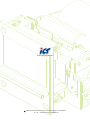
Chapter 1
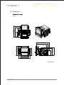
1-2. Dimensions :
26.8 [1.06]
66.0 [2.60]
145.0 [5.71]
124.0 [4.88]
Figure 1
157.0 [6.18]
145.0 [5.71]
101.3 [3.99]
92.2 [3.63]
60.5 [2.39]
92.2 [3.63]
95.0 [3.74]
120.0 [4.72]
124.0 [4.88]
82.0 [3.23]
100.0 [3.94]
138.0 [5.43]
Unit:mm[inch]
www.ictgroup.com.tw
4
Chapter 1
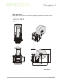
Large paper roller A & B can be setup by adjusting large paper roll fixed mount.
A
Figure 2
150.0 [5.91]
147.0 [5.79]
82.0 [3.23]
80.0 [3.15]
220.0 [8.66]
298.4 [11.75]
150.0 [5.91]
106.0 [4.17]
188.4 [7.42]
28.0 [1.10]
183.1 [7.21]
150.0 [5.91]
293.1 [11.54]
Unit:mm{inch}
5
www.ictgroup.com.tw
Chapter 1
B
Figure 3
150.0 [5.91]
147.0 [5.79]
0.0
[8.
6
6]
82.0 [3.23]
22
80.0 [3.15]
150.0 [5.91]
265.9[10.46]
155.9[6.13]
150.0 [5.91]
106.0 [4.17]
28.0 [1.10]
211.5[8.32]
321.5[12.65]
Unit:mm{inch}
www.ictgroup.com.tw
6
Chapter 2
2. Installation :
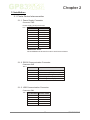
2-1. Printer Device Interconnection
2-1-1. Power Supply Connector
Connector CN9
Power supply (Vbat) is 24V±10%
Table 1
PIN NUMBER SIGNAL NAME
1
2
3
4
5
6
7
8
9
GND
GND
GND
GND
GND
Vbat
Vbat
Vbat
NC
IMPORTANT NOTE:
Wires AWG26 must be used in order to avoid current losses.
2-1-2. RS232 Communication Connector
Connector CN7
Table 2
PIN NUMBER
1
2
3
4
5
SIGNAL NAME
GND
Transmit data (TxD, printer output)
Receive data (RxD, printer input)
CTS/DSR (printer input)
RTS/DTR (printer output)
2-1-3. USB Communication Connector
Connector CN1
Table 3
PIN NUMBER SIGNAL NAME
1
2
3
4
5
VBus
DD+
N.C
GND
7
www.ictgroup.com.tw
Chapter 2
2-1-4. RS232/ USB Mode Selection
RS232 or USB mode will be chosen via software automatically after
the first character is received. At power-up, both RS232 and USB
communications are active. If the first character is received on the
RS232 port, the communication will be RS232, and vice versa for USB.
This first character will be interpreted like any other incoming byte into
the printer.
2-1-5. Near End of Paper Sensor
Connector CN12
Table 4
PIN NUMBER SIGNAL NAME
1
2
3
www.ictgroup.com.tw
LED
OPTO
GND
8
Chapter 2
2-2. Bezel
Figure 4
Figure 5
9
www.ictgroup.com.tw
Chapter 2
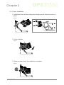
2-3. Printer Installation
1. Install bezel first, and then hold printer facing to panel, hook two levers on
panel.
Figure 6
2. Let go of printer.
Figure 7
3. When you hear “click”, the installation’s complete.
Figure 8
Click
www.ictgroup.com.tw
10
Chapter 2
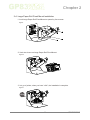
2-4. Large Paper Roll Fixed Mount Installation
1. Lock Large Paper Roll Fixed Mount on panel by four screws.
Figure 9
2. Hook two levers on Large Paper Roll Fixed Mount.
Figure 10
3. Let go of printer, when you hear “click”, the installation’s complete.
Figure 11
Click
11
www.ictgroup.com.tw
Chapter 2
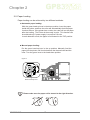
2-5. Paper Loading
Paper loading can be achieved by two different methods:
l Automatic paper loading:
With the green head-up lever in the down position, insert the paper
inside the printer, and then the roller will automatically feed the paper
for about 40 mm. If the printer has a cutter, the cutter will cut the paper
after the loading. The Printer is then ready to print. This function can
be achieved only if power supply is more than 18 volts.
In mark detection mode, the paper is fed forward to the TOF position.
l Manual paper loading:
Put the green head-up lever in the up position. Manually feed the
paper into the printer until it exits between the thermal head and the
roller. Turn the green lever to the head-down position.
Figure 12
Up
Down
Green head-up lever
Please make sure the paper roll is toward to the right direction.
www.ictgroup.com.tw
12
Chapter 3
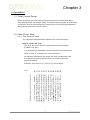
3. Operation :
3-1. Ticket Content Design
Users can design the ticket content by any txt files such as Microsoft Word.
Then print the ticket out through GP83. The Printer Show program in GP83 driver
can also be used as ticket designing. Please refer to the following paragraph to
design ticket content from Printer Show.
3-2. About Printer Show
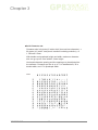
3-2-1. Text Printing Format
The controller board has three resident sets of 224 characters:
l 8x16, 12x20, and 7x16.
The 8x16 and 12x10 fonts include the Euro currency symbol
(Position 128, 80h).
12 characters are selectable from the international character set:
Refer to ESC “R” command for more information.
All character bitmaps will be shown with their hexadecimal code
(row being the most significant nibble, and column the least
significant nibble).
Example: ascii code for “A” is 41 hex (or 65 decimal).
Table 5
13
www.ictgroup.com.tw
Chapter 3
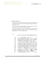
l 8x16 Character set:
Character size is 9 pixels (8 “active dots” plus one inter-character) x
20 pixels (16 “active” dots plus 4 interlines including underline), or
1.125mmx 2.5mm.
With double and quadruple height and width, maximum character
size can go up to 4.5mm width x 10mm height.
Horizontal character spacing and line spacing may be adjusted via
the software. Character per line is up to 71 in standard text, 35 in
double width, and 17 in quadruple width.
Table 6
www.ictgroup.com.tw
14
Chapter 3
l 12x20 Character set:
Character size is 13 pixels (12 “active dots” plus one inter-character)
x 24 pixels (20 “active” dots plus 4 interlines including underline), or
1.6 2 5 m m x 3 m m.
With double and quadruple height and width, maximum character
size can go up to 6.5 mm width x 12mm height.
Horizontal character spacing and line spacing may be adjusted via
the software. Character per line is up to 49 in standard text, 24 in
double width, and 12 in quadruple width.
Table 7
15
www.ictgroup.com.tw
Chapter 3
l 7x16 Character set:
Character size is 8 pixels( 7 “active dots” plus one inter-character) x
20 pixels(16 “active” dots plus 4 interlines including underline),
1 mm by 2.5mm.
With double and quadruple height and width, maximum character
size can go up to 4mm width by 10mm height.
Horizontal character spacing and line spacing may be adjusted via
the software. Character per line is up to 80 in standard text, 40 in
double width, and 20 in quadruple width. This font includes the
Katakana characters set.
Table 8
www.ictgroup.com.tw
16
Chapter 3
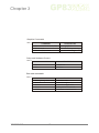
3-2-2. Operating Control Codes
Control Codes are non-printable characters or sequences of characters
that control the operation of the printer. Within the following description,
a control code causes the printer to interpret the following byte as part
of a command and not as a printable character.
Setup and Hardware Control
Table 9
COMMAND
GS / n
GS s n1 n2
GS D n
ESC @
ESC v
ESC I
GS B n
GS p n
GS P n1 n2
GS M n1 n2
ESC n s
DESCRIPTION
Set printing speed / maximum peak current
Set maximum print out speed
Set print intensity
Reset printer
Send printer status
Send printer identity
Serial communication settings
Set paper loading pause
Set paper loading length
Set paper loading speed
Near end of paper status
Text and General Commands
Table 10
COMMAND
ESC % n
ESC R n
ESC 2 n
ESC 3 n
ESC SP n
ESC b n
ESC c n
ESC C n
ESC ! n
ESC { n
LF
CR
ESC J n
ESC j n
CAN
DESCRIPTION
Select internal font
Select international character set
Set line pre-spacing
Set line spacing
Set character spacing
Set inverse video printing
Set maximum number of columns
Set text justification
Set print mode
Set/reset rotated characters
Line feed
Carriage return
Feed paper (n dot lines) forward
Feed paper (n dot lines) backward
Cancel print data buffer (text mode)
17
www.ictgroup.com.tw
Chapter 3
Graphics Commands
Table 11
COMMAND
ESC * n1 n2 n3 n4 n5 n6, data
ESC $ n1,n2
ESC V n1,n2,n3 data
DESCRIPTION
Print graphics
Horizontal dot positioning
Horizontal bit image
Setup and Hardware Control
Table 12
COMMAND
DESCRIPTION
Partial cut
Full cut
ESC m
ESC i
Bar code commands
Table 13
COMMAND
GS k n [Start] <data> NUL
GS h n
GS w n
GS H n
GS R n
www.ictgroup.com.tw
DESCRIPTION
Print bar code
Barcode height
Barcode magnification
Text position in barcode
Set/reset rotated barcode
18
Chapter 3
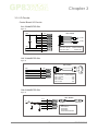
3-3. I/O Circuits
Control Board I/O Circuits
CN1 CONNECTER PIN
Figure 13
GND
PIN1
PIN2
PIN3
PIN4
PIN5
PIN6
PIN7
+24V
PIN8
PIN9
WEL-RG808
GND
1
2
3
4
5
6
7
8
9
GND
GND
GND
GND
+24V
+24V
Y(3.2Φ)
Y(3.2Φ)
POWER
PIN 1~PIN 5- BLACK......POWER GROUND
PIN 6~PIN 8- RED................POWER(+24V)
+24V
NC
CN7 CONNECTER PIN
Figure 14
WEL-RG807
GND
PIN1
TXD
PIN2
RXD
PIN3
CTS
PIN4
RTS
PIN5
1
2
3
4
5
GND
TXD
RXD
RS-232
PIN 1- YELLOW.....POWER GROUND
PIN 2- ORANGE...........................TXD
PIN 3- RED.................................. RXD
PIN 4- BROWN.............................CTS
PIN 5- BLACK...............................RTS
CTS
RTS
D-SUB(F)
CN9 CONNECTER PIN
Figure 15
WEL-RG809
+3.3V
D-
R
R
D+
R
R
GND
PIN1
3.3V
PIN2
D-
PIN3
D+
PIN4
NC
PIN5
GND
19
MINI USB 5P
USB-A-TYPE
USB
PIN1:USB3.3V
PIN2:USB DPIN3:USB D+
PIN5:POWER GROUND
www.ictgroup.com.tw
Chapter 4
4. Maintenance :
1. Remove GP83 printer from panel.
Figure 16
2. Unlatch the cutter from printer panel fixed mount to inspect for foreigner objects
and clean inner part.
Figure 17
OK
DO NOT USE
www.ictgroup.com.tw
Mild, non-abrasive, soap water.
Organic solvent , Alcohol, Volatility liquid
20
Chapter 5
5. Troubleshooting :
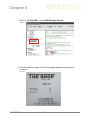
5-1. Graphic Displacement (For USB Only)
If you use Printer Show to setup the ticket by USB interface, you may follow
the steps to solve the graphic displacement as below:
Figure 18
Graphic Displacement
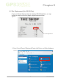
1. Please restart GP83 Driver after installation to make sure GP83
works normally.
2. Start Printer Show.
Figure 19
21
www.ictgroup.com.tw
Chapter 5
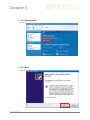
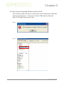
3. Click on “CP324 HRS” under “APS Windows Drivers”.
Figure 20
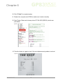
4. Print the ticket out again to test if the graphic displacement problem
is solved.
Figure 21
www.ictgroup.com.tw
22
Chapter 5
5-2. Text Displacement (For RS-232 Only)
If you use Printer Show to setup the ticket by RS-232 interface, you may
follow the steps to solve the graphic displacement as below:
Figure 22
Text Displacement
1. Enter Control Panel of Windows XP, and click Printer and Other Hardware.
Figure 23
23
www.ictgroup.com.tw
Chapter 5
2. Click “Add a printer”.
Figure 24
3. Click “Next”.
Figure 25
www.ictgroup.com.tw
24
Chapter 5
4. Cancel “Automatically detect and install my Plug and Play printer”.
Figure 26
5. Choose “COM1” or “COM2”.
Figure 27
25
www.ictgroup.com.tw
Chapter 5
6. Choose “APS” under “Manufacturer”, and “CP 324 HRS” under “Printers”.
Figure 28
7. Choose “Keep existing driver”.
Figure 29
www.ictgroup.com.tw
26
Chapter 5
8. Set the printer name as CP 324 HRS (RS232), then choose “No” to not
use this printer as a default printer.
Figure 30
9. Choose “No” on “Print Test Page”.
Figure 31
27
www.ictgroup.com.tw
Chapter 5
10. Click “Finish” to complete setup.
11. Restart the computer and GP83 to make sure it works normally.
12. Start Printer Show and choose printer CP 324 HRS (RS232) which was
just added.
Figure 32
13. Print the ticket out again to test if the text displacement problem is solved.
Figure 33
www.ictgroup.com.tw
28
Chapter 5
5-3. Opto Sensor Inspecting Disable on printer show
If the window as figure 34 pops out during opto sensor inspecting, it dedicates
software operating error. Users must connect USB cable and setup as
figure 35 to inspect opto sensor value.
Figure 34
Figure 35
29
www.ictgroup.com.tw
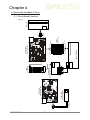
Chapter 6
6. Parts and Assembly Views:
6-1. Circuit Board Overview
Figure 36
CUTTER
MH-A4
(4PIN)
1
2
3
4
PH-A16
WEL-RG801
(16PIN)
PH-A16
(5PIN)
CN1
MH-A4
CN2
MH-A5
WEL-RG805
(9PIN)
MH-A9
(4PIN)
MH-A9
Harness Adapter Board
(AA341D10)
CN3
4
3
2
1
THERMAL HEAD
CPU Board Top
(AA341A20)
PAPER SENSOR
(AA341B10)
CPU Board Bottom
(AA341A20)
WERG802
(3PIN)
MH-A3
30
www.ictgroup.com.tw
3
2
1
5
4
3
2
1
1
2
3
4
5
6
7
8
9
9
8
7
6
5
4
3
2
1
16
15
14
13
12
11
10
9
8
7
6
5
4
3
2
1
16
15
14
13
12
11
10
9
8
7
6
5
4
3
2
1
Taiwan
International Currency Technologies Corporation
Ji-Hong Building, No 24, Alley 38, Lane 91, Nei-hu Rd., Sec. 1, Taipei, Taiwan, R.O.C.
Tel: 886-2-2797-1238 ‧ Fax: 886-2-2797-1634
[email protected] (For Sales) ‧ [email protected] (For Customer Service)
Website: www.ictgroup.com.tw
www.ictgroup.com.tw
2008 International Currency Technologies Corporation
V. 5.0
Part Number: H6050D-R