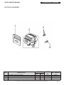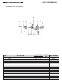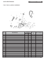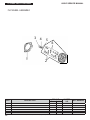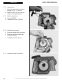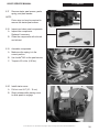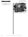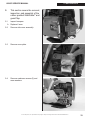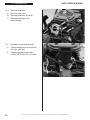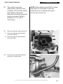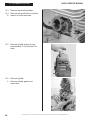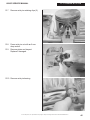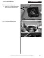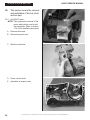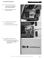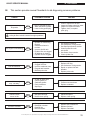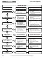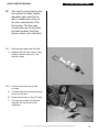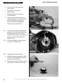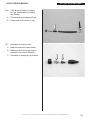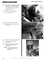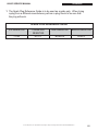
1
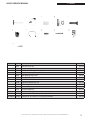
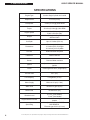
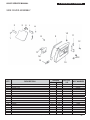
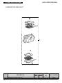
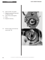
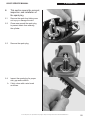
660GC
SERVICE MANUAL
© 2011 ICS | Blount, Inc. Specifications and pricing are subject to change without notice. P/N 550416 REV06012011
660GC SERVICE MANUAL
SECTION
SECTION TITLE
SERVICE MANUAL USE
PAGE NUMBER
2
1
TOOLS
3
2
SAW SPECIFICATIONS
4
3
SERIAL NUMBER LOCATION
5
4
SPARE PARTS DIAGRAMS (TORQUE SPECS & LOCTITE® APPLICATION)
6
5
AIR INTAKE
19
6
SPARK PLUG
21
7
CLUTCH & RIM SPROCKET
23
8
STARTER SYSTEM
27
9
WALLWALKER®
33
10
CYLINDER COVER
35
11
MUFFLER
39
12
CARBURETOR
41
13
CYLINDER & PISTON
43
14
WATER HOSE
52
15
IGNITION COIL
53
16
FLYWHEEL
55
17
FRONT HANDLE
57
18
FUEL TANK
58
19
CRANKCASE
60
20
BAR STUDS & BAR PAD
68
21
CHAIN TENSIONER
69
22
CARBURETOR TUNING
70
23
IDLE SPEED ADJUSTMENT
74
24
TROUBLESHOOTING DIAGRAMS
75
25
TROUBLESHOOTING FUEL SYSTEM LEAKS
77
26
TROUBLESHOOTING CRANKCASE LEAKS
80
APPENDIX
1. SPARK PLUG REFERENCE GUIDE
© 2011 ICS | Blount, Inc. Specifications and pricing are subject to change without notice. P/N 550416 REV06012011
81
1
SERVICE MANUAL USE
660GC SERVICE MANUAL
Service Manual Use
This manual contains all the technical information necessary for carrying out repairs on the
660GC saw. For safe, efficient work, it is of prime importance that the values indicated
be adhered to. Routine periodic maintenance is covered in the operator’s manual included
with each saw.
General Shop Rules
• Always use the right tools for the job, otherwise components may be damaged.
• Use a plastic dead blow mallet to separate parts attached solidly to each other.
• Mark mating parts as a reassembly reference.
• Keep component parts together as a group. Assemble screws and nuts into
appropriate subgroups.
• When reassembling, clean all parts carefully, lubricate moving parts and replace
all oil seals, o-rings, gaskets, washers and self-locking nuts.
• For best results, use only original ICS® replacement parts.
General Recommendations
• Some procedures in this manual require the use of special tools. A complete tool kit
for ICS® saws is available from ICS®.
• Detailed carburetor maintenance and overhaul information is available in Walbro’s Diaphragm Carburetor Service Manual. Walbro can be contacted at http:\\www.walbro.com
or by calling 1.989.872.2131.
2
© 2011 ICS | Blount, Inc. Specifications and pricing are subject to change without notice. P/N 550416 REV06012011
660GC SERVICE MANUAL
1. TOOLS
Key #
Part No. Description
MSRP
1
71521
Scrench 13-19 mm
$10.55
2
71541
Pressure Gauge Bulb
$47.40
3
71542
Coil/Flywheel Timing Shim
4
71543
Cylinder Assembly Clamps & Piston Stop
$10.55
5
73462
Main Bearing Driver Tool
$38.65
6
71546
Shock Absorber Tool
$22.15
7
71547
Spark Tester
$46.35
8
71548
Flywheel Disassembly Tool
$31.45
$5.25
9
71550
Limiter Cap Puller
10
71565
Electronic Tachometer
11
71573
Tuning Screwdriver
$10.55
Not Shown 71625
Carburetor Tuning Kit
$99.95
Not Shown 505882
2-Stroke Oil, 25:1 Mix, 5.2 oz (158 ml) (6-Pack)
$18.00
Not Shown 505883
2-Stroke Oil, 25:1 Mix, 5.2 oz (158 ml) (24-Pack)
$55.00
© 2011 ICS | Blount, Inc. Specifications and pricing are subject to change without notice. P/N 550416 REV06012011
$89.25
$240.00
3
2. SPECIFICATIONS
660GC SERVICE MANUAL
SPECIFICATIONS
4
Engine Type
2-stroke Single Cylinder Air Cooled
Displacement
3.9 cu-in (64 cc)
Horsepower
4.2 HP (3.1 kw) @ 9,500 RPM
Torque
32 in-lbs (3.6 Nm) @ 6,000 RPM
Engine Speed
11,500 +/- 500 rpm (max)
2,800-3,200 rpm (idle)
Weight
18.2 lbs (8.3 kg) without guidebar and
diamond chain
Cut Depth
Up to 10 inches (25.4 cm)
Dimensions
17 inches (44 cm) length
10 inches (25.5 cm) height
11.6 inches (29.5 cm) width
Air Filter
Water Resistant Polyester
Carburetor
Walbro HDA225
Starter
Dust and Water resistant
Ignition
Special water resistant electronic
ignition Clutch
Centrifugal three shoe, single spring
Fuel Mix ratio
25:1 (4%)
Fuel Capacity
0.26 gallons (1 Liter)
Water Supply
Minimum 20 psi (1.5 bar)
Water Flow
Minimum 2 gpm (8 lpm)
Noise Level
101 dB at 3 ft (1m)
Vibration Level
6.2 m/s2 (front handle)
7.3 m/s2 (rear handle)
Engine Break-in Period
One tank, without cutting, cycling
throttle
Spark Plug
Champion CJ7Y, Bosch BWS7F, or
NGK BPMR7A.
Electrode gap .020 in (0.5 mm)
© 2011 ICS | Blount, Inc. Specifications and pricing are subject to change without notice. P/N 550416 REV06012011
660GC SERVICE MANUAL
3. SERIAL # LOCATION
3 660GC serial number series.
© 2011 ICS | Blount, Inc. Specifications and pricing are subject to change without notice. P/N 550416 REV06012011
5
660GC SERVICE MANUAL
4. SPARE PARTS DIAGRAM
4 This section covers torque, Loctite®, and lubrication requirements of the individual c omponents. The key numbers used are not related to the key numbers in the 660GC Replacement Parts Price List.
CYLINDER & PISTON ASSEMBLY
2
3
4
5
6
KEY
1
2
3
4
5
6
6
DESCRIPTION
SPARK PLUG
CYLINDER BOLT
DECOMPRESSION VALVE
CYLINDER BASE GASKET
COMPLETE CYLINDER & PISTON ASSEMBLY
WRIST PIN NEEDLE BEARING
TORQUE
Nm
in‑lbs.
27.5
10.7
12.8
243
95
113
LOCTITE®
PART NUMBER
242
X
© 2011 ICS | Blount, Inc. Specifications and pricing are subject to change without notice. P/N 550416 REV06012011
73199
73874
71642
505439
505428
505403
4. SPARE PARTS DIAGRAM
660GC SERVICE MANUAL
CRANKCASE ASSEMBLY
5
6
3
4
2
7
8 8
9
7
10
14
13
16
15
KEY
1
2
3
4
5
6
7
8
9
10
11
12
13
14
15
16
DESCRIPTION
CRANKCASE PLUG
TANK PLUG
CRANKCASE
CRANKCASE DOWEL PIN
FUEL LINE GROMMET
CRANKCASE GROMMET
CRANKSHAFT BEARING
BAR MOUNTING STUD
TENSIONER
BAR MOUNT PAD COVER PLATE
SCREW, 5 X 50 mm
WASHER
CRANKCASE BOLT
CRANKCASE GASKET
CHOKE LEVER BUSHING
CHOKE LEVER
12
TORQUE
Nm
in‑lbs.
11
LOCTITE®
PART NUMBER
242
4.9
43
X
7.9
69
X
© 2011 ICS | Blount, Inc. Specifications and pricing are subject to change without notice. P/N 550416 REV06012011
505407
512461
537665
73281
505627
505408
505375
509555
505393
505467
509709
73897
73930
505440
73955
505409
7
660GC SERVICE MANUAL
4. SPARE PARTS DIAGRAM
CLUTCH & CRANKCASE ASSEMBLY
2
3
6
1
8
10
4
5
7
9
KEY
1
2
3
4
5
6
7
8
9
10
11
11
TORQUE
Nm
in‑lbs.
DESCRIPTION
CRANKSHAFT RETAINER SEAL
CRANKCASE SEAL RETAINER
WASHER
BOLT
CLUTCH SPACER
CLUTCH BEARING
8T RIM SPROCKET KIT
CLUTCH CUP WITH SPLINED ADAPTOR
CLUTCH SPACER INSIDE
CLUTCH
CLUTCH SPRING
2.9
26
33.3
295
LOCTITE®
PART NUMBER
242
X
540139
505423
73285
73940
505421
505378
70949
505422
505436
505442
505434
1
2
4
2
3
1
KEY
1
2
3
4
5
8
DESCRIPTION
CRANKSHAFT SEAL
CRANKSHAFT BEARING
CRANKSHAFT ASSEMBLY
WRIST PIN NEEDLE BEARING
CRANKSHAFT BUSHING
5
TORQUE
Nm
in‑lbs.
LOCTITE®
PART NUMBER
242
X
© 2011 ICS | Blount, Inc. Specifications and pricing are subject to change without notice. P/N 550416 REV06012011
505381
505375
505397
505403
509487
660GC SERVICE MANUAL
4. SPARE PARTS DIAGRAM
MUFFLER ASSEMBLY
3
4
KEY
1
2
3
4
DESCRIPTION
CYLINDER-TO-MUFFLER GASKET
MUFFLER
MUFFLER SCREW & WASHER
LOWER MUFFLER SCREW
TORQUE
Nm
in‑lbs.
8.8
5.8
LOCTITE®
PART NUMBER
242
78
52
© 2011 ICS | Blount, Inc. Specifications and pricing are subject to change without notice. P/N 550416 REV06012011
505385
537692
548518f
73866
9
4. SPARE PARTS DIAGRAM
660GC SERVICE MANUAL
CARBURETOR ASSEMBLY
9
1
3
2
5
1
10
13
14
4
6
KEY
11
7
DESCRIPTION
SCREW
8
10
12
TORQUE
Nm
in‑lbs.
4.9
LOCTITE®
PART NUMBER
242
43
505469
2
WASHER
73897
3
OUTER INTAKE MANIFOLD
507427
4
OUTER INTAKE MANIFOLD FLANGE SCREW
5
OUTER INTAKE MANIFOLD FLANGE
505384
6
COMPENSATOR TUBE
505382
7
CARBURETOR SPRING
73888
8
CARBURETOR, WALBRO
517742
9
PULSE TUBE
71751
10
CARBURETOR MOUNTING BRACKET
11
SCREW
12
ADJUSTMENT GUIDE
4.9
13
INTAKE MANIFOLD
INTAKE MANIFOLD CLAMP
X
73901
505411
4.0
14
43
35
X
73866
505391
505383
1.0
11
© 2011 ICS | Blount, Inc. Specifications and pricing are subject to change without notice. P/N 550416 REV06012011
73867
4. SPARE PARTS DIAGRAM
660GC SERVICE MANUAL
FUEL TANK & HANDLE ASSEMBLY
4
13
3
2
5
6
12
9
1
10
8
11
8
8
18
19
7
26
17
14 15
20
7
25
KEY
1
2
3
4
5
6
7
8
9
10
11
12
13
14
15
16
17
18
19
20
21
22
23
24
25
26
24
19
22
21
16
23
DESCRIPTION
REAR HANDLE HALF
SCREW
THROTTLE LEVER
THROTTLE LINKAGE ASSEMBLY
TRIGGER LOCKOUT LEVER SPRING
TRIGGER LOCKOUT LEVER
SHOCK ABSORBER
SHOCK ABSORBER WITH SCREW
REAR HANDLE SHOCK ABSORBER
BUMPER, SHOCK ABSORBER, FUEL TANK TOP
FUEL TANK
FRONT HANDLE BOLT
FRONT HANDLE
WASHER
SCREW
RUBBER WATER DEFLECTOR
FUEL BREATHER COMPLETE
FUEL BREATHER, REMOTE
FUEL FILTER CLIP
TUBE CLAMP
BREATHER TUBE ELBOW
BREATHER TUBE BODY
FUEL LINE
FUEL FILTER
FUEL CAP O-RING
FUEL CAP ASSEMBLY, WITH OUTER SEAL RIING
TORQUE
Nm
in‑lbs.
LOCTITE®
PART NUMBER
242
1.0
9
4.0
4.0
35
35
7.8
69
X
8.8
78
X
© 2011 ICS | Blount, Inc. Specifications and pricing are subject to change without notice. P/N 550416 REV06012011
548392
73976
71749
71750
73988
73987
505387
505658
505425
73270
548391
73983
548483
73897
73982
505445
71748
71761
71588
71760
71759
71751
73375
73459
73448
71739
11
4. SPARE PARTS DIAGRAM
660GC SERVICE MANUAL
FLYWHEEL ASSEMBLY
3
1
KEY
1
2
3
4
5
6
12
DESCRIPTION
FLYWHEEL SHROUD
FLYWHEEL
NUT
WASHER
WASHER
STARTER PAWL ASSEMBLY
4
5
6
2
TORQUE
Nm
in‑lbs.
24.5
217
6.8
60
LOCTITE®
PART NUMBER
242
© 2011 ICS | Blount, Inc. Specifications and pricing are subject to change without notice. P/N 550416 REV06012011
548514
548515
73891
73911
73912
508852
660GC SERVICE MANUAL
4. SPARE PARTS DIAGRAM
IGNITION ASSEMBLY
9
6 7 8
10
1
2
3
4
5
11
KEY
1
2
3
4
5
6
7
8
9
10
11
DESCRIPTION
IGNITION TOGGLE SWITCH NUT
IGNITION TOGGLE PLATE ON/OFF
IGNITION TOGGLE SWITCH
TOGGLE SWITCH CONNECTING PLATE
IGNITION TOGGLE CABLE
SCREW
WASHER
WASHER
SPARK PLUG BOOT W/SPRING
SPARK PLUG SPRING
IGNITION COIL WITH SPARK PLUG LEAD & PRIMARY
TORQUE
Nm
in‑lbs.
2.9
26
LOCTITE®
PART NUMBER
242
X
© 2011 ICS | Blount, Inc. Specifications and pricing are subject to change without notice. P/N 550416 REV06012011
73239
73238
73237
71449
73919
73914
73285
73890
73241
73917
505426
13
660GC SERVICE MANUAL
4. SPARE PARTS DIAGRAM
STARTER ASSEMBLY
4
2
3
5
6
7
1
11
KEY
1
2
3
4
5
6
7
8
9
10
11
14
DESCRIPTION
SCREW
STARTER ROPE HANDLE
STARTER ROPE
STARTER ASSEMBLY
STARTER CASE PLATE
RECOIL HOUSING SCREW
STARTER PULLEY WASHER
STARTER ASSEMBLY CAP
STARTER PULLEY SCREW
STARTER ROPE PULLEY
STARTER COIL SPRING & HOUSING
10
8
9
TORQUE
Nm
in‑lbs.
6.8
60
2.9
26
LOCTITE®
PART NUMBER
242
X
© 2011 ICS | Blount, Inc. Specifications and pricing are subject to change without notice. P/N 550416 REV06012011
73230
505514
508854
537666
71451
505380
73905
508853
73907
508857
73909
660GC SERVICE MANUAL
4. SPARE PARTS DIAGRAM
AIR FILTER ASSEMBLY
17
16
15
KEY
1
2
3
4
5
6
7
8
9
10
11
12
13
14
15
16
17
DESCRIPTION
AIR FILTER O-RING
FILTER COVER SCREW
AIR FILTER COVER ASSEMBLY (WITH 3 SCREWS)
AIR FILTER FLANGE
AIR FILTER CANISTER, POLYESTER
PREFILTER PLASTIC, SECONDARY FILTER
WASHER
CYLINDER COVER SCREW
FILTER SUPPORT SCREW
FILTER SUPPORT
CYLINDER COVER
O-RING
COMPENSATOR TUBE
TUBE CLAMP
FILTER COVER GASKET
BREATHER GROMMET
FILTER CANISTER GASKET
TORQUE
Nm
in‑lbs.
4.0
35
4.0
4.9
35
43
LOCTITE®
PART NUMBER
242
X
X
© 2011 ICS | Blount, Inc. Specifications and pricing are subject to change without notice. P/N 550416 REV06012011
73331
73992
537661
71758
71752
73336
73897
505429
505437
73338
537660
71472
505382
71760
71756
71763
73335
15
660GC SERVICE MANUAL
4. SPARE PARTS DIAGRAM
WATER DELIVERY SYSTEM
11
8
9
6
4
7
7
2
8
10
5
1
KEY
1
2
3
4
5
6
7
8
9
10
11
16
3
DESCRIPTION
WATER HOSE GASKET
FITTING
RING NUT
WATER HOSE O-RING
WATER SHUT-OFF VALVE
FITTING
FITTING
HOSE CLAMP
WATER HOSE
HOSE HANGER
WATER HOSE COVER
TORQUE
Nm
in‑lbs.
LOCTITE®
PART NUMBER
242
© 2011 ICS | Blount, Inc. Specifications and pricing are subject to change without notice. P/N 550416 REV06012011
71469
71467
71457
71468
71458
71466
71454
71465
509488
71461
71464
660GC SERVICE MANUAL
4. SPARE PARTS DIAGRAM
SIDE COVER ASSEMBLY
2
3
4
5
6
10
1
9
8
7
11
12
17
16
13
15
KEY
1
2
3
5
6
7
8
9
10
11
12
13
14
15
16
17
DESCRIPTION
GUARD FLAP SCREW
GUARD FLAP MOUNTING BRACKET, FRONT
GUARD FLAP
NUT
GUARD FLAP MOUNTING BRACKET, BACK
GUARD FLAP NUT
BOLT
RUBBER BUMPER, COVER
SIDE COVER GASKET
MOUNTING NUT
RUBBER WALLWALKER
SCREW
SIDE COVER NUT
SIDE COVER
FITTING
SIDE COVER PLATE
SCREW
14
TORQUE
Nm
in‑lbs.
4.9
27.5
LOCTITE®
PART NUMBER
242
71479
505491
505492
43
243
X
© 2011 ICS | Blount, Inc. Specifications and pricing are subject to change without notice. P/N 550416 REV06012011
505490
505468
73983
73310
505417
509852
505493
73982
73958
537662
71454
505419
71487
17
4. SPARE PARTS DIAGRAM
660GC SERVICE MANUAL
CARBURETOR REPAIR KIT
2
1
2
KEY
1
2
18
DESCRIPTION
CARBURETOR REPAIR KIT
CARBURETOR WALBRO HDA-225
TORQUE
Nm
in‑lbs.
LOCTITE®
PART NUMBER
242
© 2011 ICS | Blount, Inc. Specifications and pricing are subject to change without notice. P/N 550416 REV06012011
548394
548393
660GC SERVICE MANUAL
5
This section covers the
disassembly, inspection, and
assembly of the air induction
system.
5.1
Loosen the air filter cover screws
and remove air filter cover.
5.2
Remove air filter from cover.
5. AIR INTAKE
A Inspect air filter.
B Replace if necessary (P/N 71752).
5.3
Remove secondary filter from
air filter mount.
A Clean secondary filter with cleaning
solution and a nylon brush.
B Let dry and reinstall.
© 2011 ICS | Blount, Inc. Specifications and pricing are subject to change without notice. P/N 550416 REV06012011
19
5. AIR INTAKE
5.4
660GC SERVICE MANUAL
Inspect air filter cover gasket.
A Replace if permanently depressed
or hard due to slurry.
5.5
Inspect filter cannister gasket.
A Clean.
B Replace if necessary.
5.6
20
Secure air filter mount screws (3)
using Loctite® 242.
© 2011 ICS | Blount, Inc. Specifications and pricing are subject to change without notice. P/N 550416 REV06012011
660GC SERVICE MANUAL
6
This section covers the removal,
inspection, and installation of
the spark plug.
6.1
Remove the spark boot taking care
not to pry or damage the wire.
6.2
Clean area around the spark plug
to prevent debris from entering
the cylinder.
6.3
Remove the spark plug.
6.4
Inspect the spark plug for proper
size, gap and condition.
6. SPARK PLUG
A If dirty, clean with a wire brush
as shown.
© 2011 ICS | Blount, Inc. Specifications and pricing are subject to change without notice. P/N 550416 REV06012011
21
6. SPARK PLUG
6.5
660GC SERVICE MANUAL
Gap if necessary to 0.02” (0.5 mm).
NOTE:If the spark plug must be
replaced refer to the Spark Plug
Reference Guide on page 81
to select the correct
replacement plug.
6.6
Assemble in the reverse order.
A Make sure the plug boot is
seated completely.
22
© 2011 ICS | Blount, Inc. Specifications and pricing are subject to change without notice. P/N 550416 REV06012011
660GC SERVICE MANUAL
7
This section covers clutch
removal, rim sprocket removal,
inspection, and assembly. Refer
to sections 5 and 6 if needed.
7.1
Insert piston stop tool into
spark plug hole.
7.2
Pull starter handle until piston stops
against tool.
7.3
Remove clutch.
7. CLUTCH & RIM SPROCKET
Left hand threads – rotate
clockwise to loosen.
NOTE:If an impact wrench is available
steps 7.1 and 7.2 do not have to
be performed.
© 2011 ICS | Blount, Inc. Specifications and pricing are subject to change without notice. P/N 550416 REV06012011
23
7. CLUTCH & RIM SPROCKET
7.4
Remove all drive components.
7.5
Inspect the clutch shoes for wear.
660GC SERVICE MANUAL
A Replace if the shoe has less than
0.04” (1 mm) of material, as shown.
7.6
24
Inspect spring for cracks.
© 2011 ICS | Blount, Inc. Specifications and pricing are subject to change without notice. P/N 550416 REV06012011
660GC SERVICE MANUAL
7.7
Assemble clutch.
A
Insert top edge of clutch shoe
over spring as shown.
7.8
Snap clutch shoe into place.
7.9
Inspect the rim sprocket for wear.
7. CLUTCH & RIM SPROCKET
A Replace if the rim sprocket teeth are
worn to points, as shown on right.
© 2011 ICS | Blount, Inc. Specifications and pricing are subject to change without notice. P/N 550416 REV06012011
25
7. CLUTCH & RIM SPROCKET
7.10
660GC SERVICE MANUAL
Clean and assemble.
A Clean all parts in solvent.
B Grease needle bearing (ICS® P/N
505378) with a waterproof grease
C Assemble clutch spacer washer,
bearing, clutch cup with rim sprocket,
and inside clutch spacer washer.
7.11
Install clutch.
A Torque to 295 in-lbs (33.3 Nm)
Left hand threads
26
© 2011 ICS | Blount, Inc. Specifications and pricing are subject to change without notice. P/N 550416 REV06012011
660GC SERVICE MANUAL
8
This section covers the
removal of the starter cover,
replacement of the starter rope,
and replacement of the
recoil spring.
8.1
Remove starter cover screws (4).
8.2
Remove starter cover assembly
from saw.
8.3
Remove starter cord shield screws.
8.4
Relieve spring tension.
8. STARTER
A Pull 4-6” (10-15 cm) of rope out.
BLine rope up with notch on pulley.
C To release pulley, slowly rotate
pulley counterclockwise until spring
pressure is released. Use thumb
as a brake.
8.5
Remove rubber screw seal.
© 2011 ICS | Blount, Inc. Specifications and pricing are subject to change without notice. P/N 550416 REV06012011
27
8. STARTER
8.6
660GC SERVICE MANUAL
Remove starter pulley.
A Remove pulley screw.
8.7
Inspect coil spring.
A Replace if spring hook is damaged.
Attempting to re-bend the spring
hook may cause the hook to
break off.
BCarefully remove coil spring
and housing to prevent spring
from unwinding.
8.8
Lubricate with lightweight oil.
8.9
Replace parts carefully.
28
© 2011 ICS | Blount, Inc. Specifications and pricing are subject to change without notice. P/N 550416 REV06012011
8. STARTER
660GC SERVICE MANUAL
8.10 Inspect pulley spring catch.
A Clean with cleaning solution.
B Replace if worn or broken.
8.11 Install starter rope and tie knot.
8.12 Knot tying instructions:
A Make a loop at the end of the
pulley rope with the end of the rope
crossing on top of the tail.
A
B
C
D
B Bring the end of the rope through the
loop, creating a single loose knot.
C Pull the end of the rope down and in
front of the tail.
D Send the end through the loop a
second time, creating a double knot;
cinch tight.
© 2011 ICS | Blount, Inc. Specifications and pricing are subject to change without notice. P/N 550416 REV06012011
29
8. STARTER
660GC SERVICE MANUAL
8.13 Install pulley.
A Wind rope onto pulley clockwise
leaving 4-6”(10 - 25 cm) out.
B Make sure that the pulley spring
catch is in the spring hook.
8.14 Install center screw.
A Use Loctite® 242.
BTorque to 26 in-lbs. (2.9 Nm).
8.15 Wind the recoil spring.
A Line rope up with notch on pulley.
B Rotate the pulley with the rope
clockwise 5 times.
C Untangle rope and release.
8.16 Assemble starter cord shield.
30
© 2011 ICS | Blount, Inc. Specifications and pricing are subject to change without notice. P/N 550416 REV06012011
660GC SERVICE MANUAL
8. STARTER
8.17 Remove starter pawl screws, pawls,
spring, and plain washer.
NOTE: Piston stop tool may be required to
remove the starter pawl screws.
8.18 Inspect and clean pawl components.
A Inspect the components.
Replace if necessary.
BClean the components with a brush
and solvent.
8.19 Assemble components.
A Make sure the spring is in the
correct position.
B Use Loctite® 242 on the pawl screws.
CTorque to 60 in-lbs. (6.8 Nm).
8.20 Install starter cover.
A Pull out cord 4-6” (10 - 15 cm).
BSlowly release while placing cover
to allow pawls to engage.
© 2011 ICS | Blount, Inc. Specifications and pricing are subject to change without notice. P/N 550416 REV06012011
31
8. STARTER
660GC SERVICE MANUAL
8.21 Install starter cover screws (4).
A Use Loctite® 242.
BTorque to 60 in-lbs. (6.8 Nm).
32
© 2011 ICS | Blount, Inc. Specifications and pricing are subject to change without notice. P/N 550416 REV06012011
660GC SERVICE MANUAL
9
This section covers the removal,
inspection, and assembly of the
rubber padded WallWalker ® and
guard flap.
9.1
Inspect bumpers.
9. WALLWALKER
A Replace if worn.
9.2
Remove side cover assembly.
9.3
Remove cover plate.
9.4
Remove crankcase screws (2) and
wave washers.
© 2011 ICS | Blount, Inc. Specifications and pricing are subject to change without notice. P/N 550416 REV06012011
33
9. WALLWALKER
9.5
660GC SERVICE MANUAL
Remove and inspect guard flap.
A Replace the flap if it is torn or
damaged in any way.
9.6
Remove guard flap screws
and washers.
9.7
Reassemble in the reverse order.
A Install crankcase screws and
wave washers.
B Use Loctite® 242.
CTorque to 70 in-lbs. (7.9 Nm).
34
© 2011 ICS | Blount, Inc. Specifications and pricing are subject to change without notice. P/N 550416 REV06012011
660GC SERVICE MANUAL
10
10. CYLINDER COVER
This section covers the
disassembly and assembly of
the cylinder cover. Removal of
the air intake components and
front handle is necessary. Refer
to sections 5 and 17 if needed.
10.1 Remove the air filter mount screws.
NOTE:May require heat to
remove screws.
10.2 Remove the cylinder cover screws (3).
10.3 Remove spark plug boot from cylinder
cover taking care not to pry or
damage the wire.
10.4 Remove fuel tank breather cap
and clamp.
10.5 Partially remove intake manifold
from cylinder cover.
10.6 Remove cylinder cover.
A Pull up on front.
B Push intake manifold through hole.
C Make sure throttle linkage is
disengaged from cylinder cover.
D Guide fuel breather tube and
compensator tube through
cylinder cover.
© 2011 ICS | Blount, Inc. Specifications and pricing are subject to change without notice. P/N 550416 REV06012011
35
10. CYLINDER COVER
660GC SERVICE MANUAL
10.7 Remove stop switch leads.
10.8 Inspect cylinder cover for damage.
A Replace if necessary.
10.9 Check filter cover gasket.
A Replace if necessary.
10.10 Check cylinder cover water seal.
A Replace if necessary.
36
© 2011 ICS | Blount, Inc. Specifications and pricing are subject to change without notice. P/N 550416 REV06012011
660GC SERVICE MANUAL
10. CYLINDER COVER
10.11 Assemble in reverse order.
A Reassemble stop switch leads.
10.12 Make sure carburetor screw boot
is in place.
10.13 Install cylinder cover.
A Pull spark plug lead into slot
in cylinder cover.
B Lubricate compensating tube (1) and
fuel tank breather tube (2) with soapy
water, guide through cylinder cover
(Install compensating tube first).
NOTE:Be careful to not pull tubes away
from their point of connection.
Approximately 3/4” of tube
should protrude from
cylinder cover.
A
B (1)
© 2011 ICS | Blount, Inc. Specifications and pricing are subject to change without notice. P/N 550416 REV06012011
B (2)
37
660GC SERVICE MANUAL
10. CYLINDER COVER
C Push the cylinder cover down on the
crankcase, guide intake manifold into
cylinder cover.
D
D Align throttle linkage with cylinder
cover and crankcase.
E Install the cylinder cover screws.
Use Loctite® 242. Torque to
35 in-lbs. (4.0 Nm).
E
10.14 Install air filter mount.
A Guide carburetor compensating tube
through air filter mount. Make sure
manifold sits flat over lip on
cylinder cover (see section 10.5).
BInstall air filter mount screws (3)
using Loctite® 242.
CTorque to 43 in-lbs. (4.9 Nm).
10.15 Install air filters and cover.
A Install pre-filter.
BInstall clean air filter.
CInstall air filter flange and tighten.
D Install air filter cover and tighten.
38
© 2011 ICS | Blount, Inc. Specifications and pricing are subject to change without notice. P/N 550416 REV06012011
660GC SERVICE MANUAL
11
This section covers the
disassembly, inspection,
and assembly of the muffler.
Removal of the bumpers and
cylinder cover is necessary.
Refer to sections 9 and 10
if necessary.
11.1
Remove muffler support screws.
11. MUFFLER
11.2 Remove muffler screws located
inside the muffler.
11.3 Remove muffler and heat shield
gasket.
•
Replace any damaged components.
© 2011 ICS | Blount, Inc. Specifications and pricing are subject to change without notice. P/N 550416 REV06012011
39
11. MUFFLER
660GC SERVICE MANUAL
11.4 Install muffler.
• Insert muffler screws (2) into muffler.
• Hold muffler screws in place with heat
shield gasket.
• Thread muffler screws into cylinder with
Loctite®242. Torque to 78 in-lbs. (8.8 Nm).
11.5 Install bottom (2) muffler support
screws with Loctite®242.
• Torque top screws to 78 in-lbs. (8.8 Nm).
• Torque bottom screws to 52 in-lbs. (5.8
Nm).
40
© 2011 ICS | Blount, Inc. Specifications and pricing are subject to change without notice. P/N 550416 REV06012011
660GC SERVICE MANUAL
12
This section covers the
removal and installation of the
carburetor. Removal of the air
intake components and cylinder
cover is required. Please refer
to sections 5 and 10 or 11 if
necessary. Carburetor tuning
is covered in section 22.
12. CARBURETOR
NOTE: All saws are equipped with
carburetor model # HDA-225.
12.1 Remove throttle linkage.
A Push trigger end out of rear handle.
B Pivot linkage around.
C Remove carburetor end of linkage
from throttle rod tab on carburetor.
12.2 Remove fuel line from carburetor and
support bracker.
12.3 Remove carburetor support bracket.
A Remove carburetor support screw (1)
with #4 Torx or straight blade
screwdriver.
B
B
B Remove carburetor body screws (2).
A
© 2011 ICS | Blount, Inc. Specifications and pricing are subject to change without notice. P/N 550416 REV06012011
41
12. CARBURETOR
660GC SERVICE MANUAL
12.4 Remove carburetor.
A Remove pulse tube.
B Remove carburetor jet cover.
C Remove carburetor from
choke linkage.
A
C
12.5 Assemble in the reverse order.
A Torque carburetor body screws to
43 in-lbs. (4.9 Nm).
BTorque supporter screw with
Loctite® 242 to 43 in-lbs. (4.9 Nm).
42
© 2011 ICS | Blount, Inc. Specifications and pricing are subject to change without notice. P/N 550416 REV06012011
B
660GC SERVICE MANUAL
13
This section covers the
disassembly, inspection and
assembly of the cylinder, piston
and related components.
Removal of several component
groups is required. Refer to
sections 5, 6, 10, and 12
if necessary.
13. CYLINDER & PISTON
NOTE: When replacing the 660GC cylinder
and piston it is necessary to tune the
carburetor prior to returning the saw to
service (see section 22).
13.1 Remove carburetor base screws (3).
A Remove carburetor base bracket
from rear manifold.
B Remove carburetor base bracket
from pulse tube.
13.2 Remove pulse tube and protective
spring from cylinder base.
© 2011 ICS | Blount, Inc. Specifications and pricing are subject to change without notice. P/N 550416 REV06012011
43
13. CYLINDER & PISTON
660GC SERVICE MANUAL
13.3 Remove rear manifold clamp.
13.4 Remove rear manifold from cylinder.
A Inspect for holes and tears.
13.5 Remove cylinder screws (4) and
wave washers (2 on front and 2 on
back)
13.6 Remove cylinder.
A Remove cylinder gasket and
clean case.
44
© 2011 ICS | Blount, Inc. Specifications and pricing are subject to change without notice. P/N 550416 REV06012011
660GC SERVICE MANUAL
13. CYLINDER & PISTON
13.7 Remove wrist pin retaining clips (2).
13.8 Press wrist pin out with an 8 mm
deep socket.
13.9 Remove piston and inspect.
Replace if damaged.
13.10 Remove wrist pin bearing.
© 2011 ICS | Blount, Inc. Specifications and pricing are subject to change without notice. P/N 550416 REV06012011
45
13. CYLINDER & PISTON
660GC SERVICE MANUAL
13.11 Assemble cylinder gasket.
A Oil gasket with ICS® 2-stroke
engine oil.
BInstall and align holes and notch.
13.12 Install wrist pin bearing in rod.
A Oil bearing with ICS® 2-stroke
engine oil.
13.13 Install rings.
A Install bottom ring first. Installing
bottom ring over the top ring may
cause the ring to break.
46
© 2011 ICS | Blount, Inc. Specifications and pricing are subject to change without notice. P/N 550416 REV06012011
660GC SERVICE MANUAL
13. CYLINDER & PISTON
13.14 Ring orientation.
NOTE:Make sure both piston ring end
gaps are correctly oriented over
their locating pins in the piston
ring grooves.
13.15 Install one (1) wrist pin retaining clip.
13.16 Make sure wrist pin retaining clip is in
the proper orientation.
Improper installation may result
in serious engine damage.
NOTE:Never attempt to reuse wrist pin
retaining clips or substitute wrist
pins from another model
or brand. Install two new
retaining clips with their open
ends facing either to the
six o'clock (toward the
crankcase) or twelve o'clock
(toward the cylinder head)
position. Each retaining clip
should produce an audible
"click" as it seats in its groove
in the piston.
© 2011 ICS | Blount, Inc. Specifications and pricing are subject to change without notice. P/N 550416 REV06012011
47
13. CYLINDER & PISTON
660GC SERVICE MANUAL
13.17 Lube and partially install wrist pin.
13.18 Align piston in correct orientation.
A Make sure arrow points to
exhaust port.
EXHAUST
INTAKE
13.19 Install piston.
A Oil piston with ICS® 2-stroke oil.
B Align wrist pin with wrist pin bearing.
CComplete wrist pin installation.
D Install second wrist pin retaining clip.
Make sure wrist pin retaining
clip is in the proper orientation
(see 13.16).
48
© 2011 ICS | Blount, Inc. Specifications and pricing are subject to change without notice. P/N 550416 REV06012011
660GC SERVICE MANUAL
13. CYLINDER & PISTON
13.20 Install cylinder.
A Lubricate cylinder bore with
ICS® 2‑stroke oil.
BCompress rings with ring
compression tool.
CSlide cylinder onto piston, pushing
ring compression tool down.
13.21 Install cylinder.
A Remove ring compression tool.
BSlide cylinder down piston and
into crankcase.
C Align cylinder bolt holes with
crankcase.
13.22 Install (4) cylinder screws and
washers.
A Use Loctite® 242.
BTorque bolts to 95 in-lbs. (10.7 Nm).
© 2011 ICS | Blount, Inc. Specifications and pricing are subject to change without notice. P/N 550416 REV06012011
49
13. CYLINDER & PISTON
660GC SERVICE MANUAL
13.23 Install rear manifold.
A Apply lightweight grease on the
inside lip of the rear manifold.
B Push rear manifold onto
cylinder intake.
C Align mold seams of intake boot with
casting seams of the cylinder.
13.24 Install rear manifold clamp.
A Torque to 11 in-lbs. (1 Nm).
NOTE:Insure that the intake boot is
properly installed.
DO NOT OVER TIGHTEN
INTAKE BOOT CLAMP.
If over tightened, intake boot can
tear, resulting in an air leak which
will cause engine damage.
13.25 Install the pulse tube onto
cylinder barb.
13.26 Install protective spring onto
pulse tube.
50
© 2011 ICS | Blount, Inc. Specifications and pricing are subject to change without notice. P/N 550416 REV06012011
660GC SERVICE MANUAL
13. CYLINDER & PISTON
13.27 Install carburetor base.
A Slip pulse tube into carburetor base.
BSlip rear manifold into carburetor
base.
C Make sure rear manifold lip is flat.
13.28 Install carburetor base screws.
A Use Loctite® 242 on screws (3).
B Make sure to include stop switch wire
on front screw.
CTorque to 35 in-lbs. (4.0 Nm).
© 2011 ICS | Blount, Inc. Specifications and pricing are subject to change without notice. P/N 550416 REV06012011
51
14. WATER HOSE
14
660GC SERVICE MANUAL
This section covers water hose
and side cover.
14.1 Inspect water hose and side cover.
A Replace if damaged.
14.2 Assemble in reverse order.
14.3 Remove water hose connector from
side cover.
A Remove clamp and hose from fitting.
B Unthread fitting from side cover.
14.4 Inspect side cover for damage.
A
52
Replace if necessary.
© 2011 ICS | Blount, Inc. Specifications and pricing are subject to change without notice. P/N 550416 REV06012011
660GC SERVICE MANUAL
15
15. IGNITION COIL
This section covers the removal,
inspection, and installation of
the ignition coil. Removal of
the starter is required. Refer to
section 8 if necessary.
15.1 Remove starter flywheel shroud by
unhooking wires.
15.2 Remove ignition coil screws, wave
washers and plain washers.
15.3 Remove ignition coil.
15.4 Inspect ignition coil.
A Look for:
• Cracks
• Missing insulation
• Wear marks in wire
BClean flywheel magnets and
coil if rusty.
© 2011 ICS | Blount, Inc. Specifications and pricing are subject to change without notice. P/N 550416 REV06012011
53
15. IGNITION COIL
660GC SERVICE MANUAL
15.5 Install Ignition coil.
A Place ignition coil shim (0.012”)
on magnet counterweight side
of flywheel.
BSet ignition coil in place.
CInstall ignition coil screws, wave
washers, and plain washers with
Loctite® 242.
Holding shim, rotate flywheel magnet
around to coil.
E Torque ignition coil screws to
26 in‑lbs. (2.93 Nm).
F Remove shim, rotate flywheel to
check clearance.
15.6 Install flywheel shroud.
15.7 Route yellow ignition stop switch wire
through crankcase into carburetor
chamber.
15.8 Complete ignition wire routing.
54
© 2011 ICS | Blount, Inc. Specifications and pricing are subject to change without notice. P/N 550416 REV06012011
660GC SERVICE MANUAL
16
16. FLYWHEEL
This section covers the removal,
inspection, and installation of
the flywheel. Removal of spark
plug and the starter is required.
Refer to sections 6 and 8
if necessary.
16.1 Insert piston stop.
16.2 Remove flywheel nut, wave washer,
and plain washer.
16.3 Screw on flywheel removal tool finger
tight. Unscrew tool 1 ½ turns leaving
approximately 1/8 inch (4 mm) space
between tool and flywheel.
© 2011 ICS | Blount, Inc. Specifications and pricing are subject to change without notice. P/N 550416 REV06012011
55
16. FLYWHEEL
660GC SERVICE MANUAL
16.4 Using pliers, hold saw up by magnet
counterweight.
16.5 Strike flywheel removal tool with
a ball peen hammer. The flywheel
should release from crankshaft.
16.6 Inspect and clean flywheel. Replace
if any of the fins are broken.
16.7 Inspect cast woodruff key inside
the flywheel.
NOTE:Key is cast into flywheel.
16.8 Install flywheel, plain washer, wave
washer, and flywheel nut.
A Torque nut to 217 in-lbs. (24.5 Nm).
56
© 2011 ICS | Blount, Inc. Specifications and pricing are subject to change without notice. P/N 550416 REV06012011
660GC SERVICE MANUAL
17
This section covers the removal,
inspection, and installation of
the front handle.
17.1
Remove front handle screws (2) on
right side.
17. FRONT HANDLE
17.2 Remove front handle screws (2)
on bottom.
17.3 Install front handle.
A Roll front handle into place.
BInstall front handle screws (4).
C Use Loctite® 242.
D Torque to 69 in-lbs. (7.8 Nm).
© 2011 ICS | Blount, Inc. Specifications and pricing are subject to change without notice. P/N 550416 REV06012011
57
18. FUEL TANK
18
660GC SERVICE MANUAL
This section covers the
disassembly, inspection,
and assembly of the
vibration isolaters, fuel tank,
and rear handle.
18.1 Remove vibration isolator screws (2)
and wave washers on clutch side
of saw.
18.2 Remove vibration isolator screws (2)
and wave washers on flywheel side
of saw.
58
© 2011 ICS | Blount, Inc. Specifications and pricing are subject to change without notice. P/N 550416 REV06012011
660GC SERVICE MANUAL
18. FUEL TANK
18.3 Separate crankcase and fuel tank.
NOTE:Saws have a rubber water
deflector connected to the
front vibration isolator on the
clutch side (circled).
18.4 Remove vibration isolators (4) from
fuel tank if necessary.
NOTE: Shock absorber tool (p/n #71546)
must be used to remove vibrator
isolators.
18.5 Assemble in reverse order.
NOTE:During assembly be careful to
avoid kinking the fuel line.
Torque vibration isolators to 35 in-lbs.
(4.0 Nm).
© 2011 ICS | Blount, Inc. Specifications and pricing are subject to change without notice. P/N 550416 REV06012011
59
19. CRANKCASE
19
660GC SERVICE MANUAL
This section covers the
disassembly, inspection, and
assembly of the crankcase
seals and crankshaft bearings.
19.1 Remove outer crankshaft seal
housing screws (3) and wave
washers.
19.2 Remove crankcase bolts (5).
60
© 2011 ICS | Blount, Inc. Specifications and pricing are subject to change without notice. P/N 550416 REV06012011
660GC SERVICE MANUAL
19. CRANKCASE
19.3 Heat the flywheel side crankcase
with heat gun for 5 minutes,
approximately 150° F (65.5° C).
19.4 Remove the flywheel side crankcase
– tap crankshaft with plastic mallet.
A Suspend above work surface.
BTap with mallet.
NOTE:A nut should always be placed
on a threaded shaft when
pounding or pressing on it.
19.5 Remove the flywheel side crankcase
seal with 1/2” (13 mm) socket.
© 2011 ICS | Blount, Inc. Specifications and pricing are subject to change without notice. P/N 550416 REV06012011
61
19. CRANKCASE
660GC SERVICE MANUAL
19.6 Disassembly of crankcase.
Heat the clutch side crankcase with
heat gun to 150° F (65.5° C).
19.7 Remove crankshaft from the
clutch‑side crankcase tap crankshaft
with a plastic mallet.
A Suspend above work surface.
BTap with plastic mallet.
19.8 Remove the bearing from the
flywheel side of crankshaft.
62
© 2011 ICS | Blount, Inc. Specifications and pricing are subject to change without notice. P/N 550416 REV06012011
660GC SERVICE MANUAL
19. CRANKCASE
19.9 Remove the bearing, seal, and
bushing from the clutch side
of crankshaft.
19.10 Assembly of crankcase.
A Clean mating crankcase faces.
19.11 Heat crankcase halves to 150° F
(65.5° C).
19.12 Install bearing into crankcase halves.
19.13 Tap with bearing driver and mallet.
© 2011 ICS | Blount, Inc. Specifications and pricing are subject to change without notice. P/N 550416 REV06012011
63
19. CRANKCASE
660GC SERVICE MANUAL
19.14 Repeat with other half.
19.15 Install crankshaft into clutch side
of case.
19.16 Place clutch side crankcase seal
on crankshaft.
A Tap lightly with bearing driver
and mallet.
64
© 2011 ICS | Blount, Inc. Specifications and pricing are subject to change without notice. P/N 550416 REV06012011
660GC SERVICE MANUAL
19. CRANKCASE
19.17 Coat crankcase gasket with
ICS® 2‑stroke engine oil.
19.18 Align crankcase gasket on flywheel
side crankcase pins.
19.19 Place crankcase halves together and
align crankcase pins.
© 2011 ICS | Blount, Inc. Specifications and pricing are subject to change without notice. P/N 550416 REV06012011
65
19. CRANKCASE
660GC SERVICE MANUAL
19.20 Assemble crankcase halves –
tap with bearing driver and mallet.
19.21 Install crankcase bolts (5).
A Use Loctite® 242.
BTorque to 70 in-lbs. (7.9 Nm).
19.22 Install flywheel side crankcase seal –
tap with bearing driver and mallet.
66
© 2011 ICS | Blount, Inc. Specifications and pricing are subject to change without notice. P/N 550416 REV06012011
660GC SERVICE MANUAL
19. CRANKCASE
19.23 Assemble in reverse order
A Install outer crankshaft seal housing
with 3 bolts and use Loctite® 242.
19.24 Trim crankcase gasket flush.
© 2011 ICS | Blount, Inc. Specifications and pricing are subject to change without notice. P/N 550416 REV06012011
67
20. BAR STUDS & BAR PAD
20
660GC SERVICE MANUAL
This section covers the removal
and installation of the bar studs
and bar pad.
20.1 On 660GC saws:
NOTE:This requires the removal of the
piston and cylinder, and to split
the crankcase. (Refer to section
13 & 19 for detailed instructions)
A Remove side cover.
B Remove bar pad cover.
C Split the crankcase.
D Press out bar studs.
E Assemble in reverse order.
68
© 2011 ICS | Blount, Inc. Specifications and pricing are subject to change without notice. P/N 550416 REV06012011
660GC SERVICE MANUAL
21
21. CHAIN TENSIONER
This section covers the
removal and installation
of the chain tensioner.
21.1 Remove bar plate to expose
the chain tensioner.
21.2 Unscrew tensioner to remove.
A Remove tensioner pin.
B Remove tensioner screw keeper.
21.3 Assemble in reverse order.
NOTE:The tensioner is intended to
perform as a fuse in high load or
sudden impact situations.
(p/n 505393)
© 2011 ICS | Blount, Inc. Specifications and pricing are subject to change without notice. P/N 550416 REV06012011
69
22. CARBURETOR TUNING
22
660GC SERVICE MANUAL
This section covers carburetor tuning. Included in this section are basic settings,
idle speed adjustment, and complete adjustment.
The carburetor on a new saw is set at the factory for optimal performance and
compliance to EPA Phase II emmissions standards. However, minor adjustments
may be required in certain conditions, such as high elevation. A replacement
carburetor is not set correctly from the factory. Use the tuning instructions in this
manual to adjust carburetor to factory-recommended settings. (DO NOT adjust
the carburetor for maximum rpm. Adjusting the carburetor for maximum rpm will
cause engine damage). Always set the carburetor jets to factory settings
when replacement or complete rebuild becomes necessary.
NOTES:
• These saws are equipped with an electronic speed limiter, as part of the ignition
system. This will prevent the saw from going above 12,500 rpm. Attempting to
set the carburetor mixture to increase the speed or power beyond this limit may
seriously damage the engine.
• Always check the air filter, pre filter, fuel filter, and spark plug before making
carburetor tunings and clean or replace if necessary
70
© 2011 ICS | Blount, Inc. Specifications and pricing are subject to change without notice. P/N 550416 REV06012011
660GC SERVICE MANUAL
22. CARBURETOR TUNING
22.1 Basic Setting -
RPM Settings for saws.
H = 1 turn from closed
NOTE: Saw tuned without bar and chain installed.
L = 1 turn from closed
Idle Speed = 3,000 ± 500 rpm
Full Throttle = 12,500 ± 500 rpm
Complete carburetor readjustment.
22.2 Remove limiter cap.
A. Limiter caps can only be removed after
the cylinder cover and screw boot have
been removed. Observe orientation of
the release slots on the adjustment screw
limiter cap. See section 10 for cylinder
cover removal.
B. Insert the limiter cap puller into the
center of the limiter cap.
C. Firmly hold the tool shaft while screwing
in the puller screw until the screw head is
against the puller shaft.
D. Unscrew the puller screw, 1/4 turn and
pull straight out. Repeat for second limiter
cap.
© 2011 ICS | Blount, Inc. Specifications and pricing are subject to change without notice. P/N 550416 REV06012011
71
22. CARBURETOR TUNING
660GC SERVICE MANUAL
22.3 Using a 5/64” straight blade
screwdriver, gently turn the
adjustment screws clockwise
until completely closed.
22.4 Set the adjustment screws at
the Basic Setting:
H = 1 turns from closed
L = 1 turns from closed
The side cover must be held
tightly in place with the side
cover nuts, using a bar and
no chain. Failure to do so may
result in personal injury.
22.5 Start the saw and warm up
the engine.
22.6 With a tachometer check the saw
rpm, with bar and no chain:
A Idle = 3,000 ± 500 rpm
BIf the idle rpm does not fall into
this range, adjust the T screw,
clockwise
to raise RPM, counterclockwise to
lower RPM.
72
© 2011 ICS | Blount, Inc. Specifications and pricing are subject to change without notice. P/N 550416 REV06012011
660GC SERVICE MANUAL
22. CARBURETOR TUNING
22.7 With a tachometer check the saw full
throttle rpm, with a bar and no chain:
A Target = 12,500 ± 500 rpm
22.8 If the full throttle rpm falls below
this range, turn the H screw in
(clockwise) 1/16th of a turn at a time.
A Pulse the throttle to help stabilize
the system.
Do not hold the saw at max
rpm for more than 5 seconds or
cylinder damage could occur.
© 2011 ICS | Blount, Inc. Specifications and pricing are subject to change without notice. P/N 550416 REV06012011
73
23. IDLE SPEED ADJUSTMENT
23
660GC SERVICE MANUAL
This section covers idle speed
adjustment.
23.1 If engine stops while idling:
A Make sure the chain is
properly tensioned.
BTurn T screw clockwise until
chain begins to move.
CBack T screw out ½ turn.
23.2 If chain turns at idle:
A Back T screw out until chain
stops moving.
74
© 2011 ICS | Blount, Inc. Specifications and pricing are subject to change without notice. P/N 550416 REV06012011
660GC SERVICE MANUAL
24
24. DIAGRAMS
This section provides several flowcharts to aid diagnosing common problems.
CHECK
POSSIBLE CAUSE
The engine runs rough at
all speeds.
• Dirty or clogged air filter.
• Water has been ingested.
• Loose or dirty spark plug.
YES
REPAIR
•
•
•
•
Clean or replace the air filter.
Inspect air intake system for water.
Inspect fuel system for water.
Tighten, clean, or replace
spark plug.
A dirty air filter is the #1 reason for engine problems.
YES
• Operator is overworking
the saw.
• Carburetor mixture is
too lean.
• Incorrect fuel/oil ratio.
• Flywheel fins are clogged.
• Air deflector is missing.
• Cylinder fins are clogged.
YES
•
•
•
•
•
Uneven idle or engine
may “run away”.
YES
• Air leak at intake boot,
cylinder gasket, or
crankcase gasket.
• Faulty carburetor
diaphragm.
• Inspect air intake boot.
• Pressure test crankcase.
• Replace carburetor.
Diamond chain
moves at idle.
YES
• Idle speed too high.
• Broken clutch spring.
• Adjust idle speed.
• Replace clutch spring.
YES
• Damaged shock absorber.
• Damaged or broken
flywheel fins.
• Bent crankshaft.
• Replace shock absorbers.
• Replace flywheel.
• Replace crankshaft.
The engine is overheating.
Poor acceleration.
Excessive vibration.
Dirty or clogged air filter.
Clogged fuel filter.
Incorrect carburetor tune.
Plugged tank breather.
Blocked pulse tube.
•
•
•
•
See Operator’s Manual.
See Carburetor Tuning section.
See Saw Specifications section.
Clean flywheel fins with
wire brush.
• See Starter Cover section.
• Clean cylinder fins.
•
•
•
•
Clean or replace the air filter.
Replace fuel filter.
See Carburetor Tuning section.
Repair or replace fuel tank
breather.
• Replace pulse tube.
© 2011 ICS | Blount, Inc. Specifications and pricing are subject to change without notice. P/N 550416 REV06012011
75
24. DIAGRAMS
660GC SERVICE MANUAL
Saw Will Not Start
CHECK
POSSIBLE CAUSE
Does the engine crank?
NO
• Dirty or broken recoil
starter.
• Internal damage.
• Clean, rebuild or replace the
recoil starter.
• Inspect for internal damage such
as seized piston.
NO
• The ignition switch is
“OFF”.
• Faulty ignition ground.
• Faulty spark plug lead.
• Faulty ignition coil.
• Move switch to “ON” and re-test.
• Tighten connections or replace
ground wire.
• Repair or replace spark plug lead.
• Replace ignition coil.
NO
• Plug is soaked with fuel.
• The plug is fouled or
gapped improperly.
• Plug is internally faulty or
the wrong type.
• Dry plug, expel excess fuel from
cylinder and crankcase.
• Clean and re-gap the plug to
0.020 inch (0.05 mm).
• Replace with the correct plug –
see Spark Plug Reference Guide.
NO
• Loose spark plug.
• If below 125 psi – excess
wear on the piston,
cylinder, rings and/or
improper fuel mixture.
• Tighten plug and re-test.
• Replace piston and cylinder.
• Ensure correct fuel/oil mixuture
(25:1).
NO
• Fuel is old, varnished, or
contaminated.
• Empty tank and re-fill with fresh
fuel of the correct mixture (25:1).
•
•
•
•
•
•
•
•
YES
Is there spark?
YES
Is the spark plug firing
properly?
YES
Insure cylinder
compression is above
125 psi.
YES
Is the fuel fresh?
Is the fuel mixed 25:1?
REPAIR
YES
Is the fuel reaching the
carburetor?
NO
YES
Is too much fuel reaching
the carburetor?
Clogged fuel filter.
Damaged fuel line.
Damaged pulse tube.
Plugged fuel tank
breather.
Replace fuel filter.
Replace fuel line.
Replace pulse tube.
Repair or replace fuel tank
breather.
YES
• Carburetor is tuned
incorrectly.
• Plugged fuel tank
breather.
• Refer to Carburetor Tuning
section.
• Repair or replace fuel tank
breather.
YES
• Loose flywheel.
• Replace key and reinstall flywheel.
NO
Is the flywheel key
sheared?
76
© 2011 ICS | Blount, Inc. Specifications and pricing are subject to change without notice. P/N 550416 REV06012011
660GC SERVICE MANUAL
25
25. FUEL SYSTEM LEAKS
This section covers testing the
fuel system for leaks. Engine
starvation can result from a
leak or malfunction of any of
the main components of the
fuel system. The five main
components are the fuel tank,
fuel tank breather, fuel filter,
delivery tubes, and carburetor.
25.1 Remove and inspect the fuel filter.
A Replace the fuel filter if there is any
foreign material in the felt or the
internal screen.
25.2 Test the main fuel pick-up tube
for leaks.
A Connect tube to the pressure gauge
and to the fuel line.
B Pressurize the tube to 7psi (0.5 bar).
CIf the pressure does not maintain,
separate the fuel line from the
carburetor.
© 2011 ICS | Blount, Inc. Specifications and pricing are subject to change without notice. P/N 550416 REV06012011
77
25. FUEL SYSTEM LEAKS
660GC SERVICE MANUAL
D Plug one end of the main fuel
pick-up tube.
E Re-pressurize the tube to
7psi (0.5 bar).
F Replace the tube if pressure is
not maintained.
G If the main fuel pick-up tube does
maintain pressure, then the leak has
been isolated to the carburetor.
Refer to the Walbro Diaphragm
Carburetor Service Manual.
25.3 The fuel tank breather stabilizes the
pressure in the fuel tank preventing
both excessive pressure, which
could flood the engine, and negative
pressure, which could starve the
engine of fuel.
25.4 Fuel tank breather is located inside
the air filter compartment.
25.5 Testing the fuel tank breather.
A Attach the pressure gauge and bulb
to the fuel tank breather. Pressurize
the tube to 7psi (0.5 bar).
BThe pressure should reduce to nearly
0 psi (0 bar) over about 3 seconds.
78
© 2011 ICS | Blount, Inc. Specifications and pricing are subject to change without notice. P/N 550416 REV06012011
660GC SERVICE MANUAL
25. FUEL SYSTEM LEAKS
25.6 If the pressure does not reduce
to 0 psi, disassemble or replace
the breather.
A Disassemble by snapping off cap.
B Clean parts with solvent or fuel.
25.7 Assemble in reverse order.
A Make sure duck bill opens easily.
B Make sure that the spring taper is
oriented in the correct direction.
C Assemble by snapping cap in place.
© 2011 ICS | Blount, Inc. Specifications and pricing are subject to change without notice. P/N 550416 REV06012011
79
26. CRANKCASE LEAKS
26
660GC SERVICE MANUAL
This section covers testing the
crankcase for leaks. A leak in
the crankcase can cause the
engine not to run.
26.1 Install the intake seal flange.
A Plug cylinder pulse tube.
26.2 Install the exhaust seal flange.
26.3 Block one of the flange tubes with
a rubber plug.
26.4 Install the pressure gauge and bulb.
26.5 Pressurize the crankcase to
7psi (0.5 bar).
26.6 If the pressure does not remain
the same, use soapy water to
find the leak.
NOTE:It is recommended that this
test be performed after an
engine rebuild.
80
© 2011 ICS | Blount, Inc. Specifications and pricing are subject to change without notice. P/N 550416 REV06012011
APPENDIX
660GC SERVICE MANUAL
1 The Spark Plug Reference Guide is to be used as a guide only. When trying
a plug from a different manufacturer, perform a plug check to be sure that
the plug will work.
SPARK PLUG REFERENCE GUIDE
ICS RESISTOR
73199
CHAMPION
RESISTOR
RCJ7Y
NGK RESISTOR
BOSCH RESISTOR
BPMR7A
WSR7F
© 2011 ICS | Blount, Inc. Specifications and pricing are subject to change without notice. P/N 550416 REV06012011
81
660GC SERVICE MANUAL
ICS, Blount Inc.
4909 SE International Way
Portland, OR 97222
Tel 800.321.1240 Fax 503.653.4393
icsbestway.com
© 2011 ICS | Blount, Inc. Specifications and pricing are subject to change without notice. P/N 550416 REV06012011