1
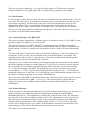
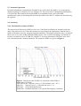
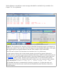
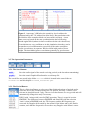
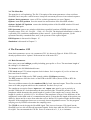
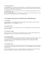
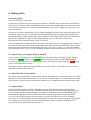
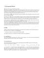
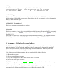
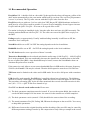
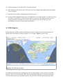
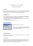
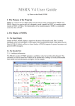
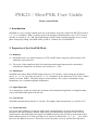
PSK21 / SlowPSK User Guide
Klaus von der Heide
1. Introduction
SlowPSK is a very sensitive digital mode for weak signals. It operates with fixed RX/TX-periods of
1, 5, 15, or 30 minutes. With a 1-minute period (48 seconds of transmission) a rate of 50 % correct
decodes is reached at -30.7 dB. The disadvantage of PSK is that it rapidly degrades in case of fast
phase changes by fading. SlowPSK with a period of 1 minute also is called PSK21.
2. Properties of the SlowPSK Mode
2.1. Demands
(1) SlowPSK needs very stable frequencies of TX and RX with a frequency drift less than 2 Hz
within the selected period.
(2) The errors of the samplerate 8000 for sound input and sound output must be determined
such that the samplerates are known at an accuracy of ±1 Hz.
2.2. Modulation
SlowPSK uses binary Phase-Shift-Keying at rates of 125/6/p bits/s with p being the stretching
factor. p = 1, 6, 18, 36 for the periods of 1, 5, 15, 30 minutes. So the fastest has 20.833 bits/s, which
justifies it's name PSK21. The pulse shape is a sinc-function. The result is a minimum-energy
modulation, not a constant-amplitude modulation.
2.3. Signal Spectrum
As a consequence of the sinc-pulse, the spectrum of the transmitted signal has a rectangular shape
with a total bandwidth equal to the bit rate.
2.4. Code Words
SlowPSK transmits binary blocks of 996 bits. The length of the transmissions is p*996*6/125 s.
2.5. Synchronization
One on the main problems of amateur weak-signal communication is to detect the transmitted
packets in time and frequency domain. PSK raises a second problem: the phase of the received
signal must be determined from this signal. SlowPSK interleaves the 664 bits of codewords with a
binary address pattern of 332 bits such that every 3rd bit of a block (bits 1, 4, 7, 10, ... , 991, 994) is
known to the addressed receiver. These bits are used for phase recovery and for block detection.
There are two types of addresses: (1) a specific binary pattern of 332 bits used as a general
broadcast address (for CQ, QRZ, QST) and (2) a unique binary pattern for each callsign.
2.6. Code Formats
In all cases three nested codes are used. The outer convolutional code (the channel code) is for error
correction. The inner code is for detection of remaining errors. It is mainly this code that prevents
from display of garbage. The third code is the source code which translates the bit arrays into
displayed text output. There is a plausibility check at this stage which refuses the display of
callsigns that do not comply with the syntax of callsigns (99.9 % of random texts are invalid!).
There are several coding schemes for different message types. Here only a brief overview is given.
For details see the SlowPSK-documentation.
2.6.1. General Messages: CQ, QRZ, QST
These three messages communicate a callsign of up to 10 characters in case of CQ or QRZ or some
general message of 10 characters in case of a QST.
The selection between 'CQ', 'QRZ', and 'QST' is encoded by two bits. Callsigns and general
messages are restricted to text of 10 characters of the SlowPSK-alphabet. They are translated into
binary patterns of 54 bits. So with the two selection bits we have a total of 56 source information
bits.
The inner code adds 15 check bits for final error detection resulting in 71 bits. The channel code
encodes the 71 bits by a rate-1/8-convolutional code of constraint length 13 (tail ended). The
resulting codeword has 664 bits. As described in 2.4, these bits are interleaved with the general
address pattern giving the transmitted block of 996 bits.
After the receiver recorded a hit with the general address pattern, the 664 soft bits are decoded by
the Viterbi algorithm resulting in a binary pattern of 71 bits. The first 56 bits are used to generate
the 15 check bits. If any of these generated check bits differs from the received check bits (bits
57...71) then the message is discarded. The probability to get correct check bits out of wrong
received data is 1 / 32749. To get the rate of displayed false decodes, the rate 1 / 32749 has to be
multiplied with the rate of false hits (<0.01) and with the rate of valid random callsigns (0.001). So
the amount of displayed garbage is very small (<0.0000000003).
The codes used in SlowPSK are unmodified linear codes. Therefore, the all-zeroes word is a correct
codeword. It would decode to QST: //////////. This special output is caught and never
displayed. It only occurs at random if heavy birdies are present and not blanked out by the
birdieblanker.
2.6.2. Private Messages
Private messages are transmissions addressed to a specific callsign. Four message-type bits allow 16
different message types within this group including contest messages with QSO-number,
Maidenhead-locator etc.. The information is encoded into 54 bits of source code. The 4 messagetype bits and 13 check bits are added to finally reach 71 bits. Other than above, the check bits are
derived from the concatenation of the 54 source code bits plus the bit pattern of the addressed
callsign (and plus the bitpattern of the sending callsign if an R or 73 is sent). This is important
because active callsigns may be very similar. Then the address correlation could show hits from
similar callsigns. These hits are discarded when the check does not succeed.
The channel code is the same as above.
2.7. Automatic Operation
Decoded information is immediately discarded if any of the check bits differs. As a consequence,
displayed garbage is extremely rare (see Chapter 10). The protection of communicated information
is so powerful, that a station can run SlowPSK in an automatic mode, where SlowPSK
automatically replies to incoming calls and runs the QSOs to the final 73 without any interaction by
the operator.
2.8. Sensitivity
2.8.1. The Block Error Rate of PSK21
The most critical elements in a PSK-receiver are (1) the block localization in frequency and time
and (2) the phase recovery. If the radio channel severely distorts the signal phase, then the rate of
failure of the phase recovery is high at marginal conditions. The utmost sensitivity only is reached if
there is no or very slow fading. Medium fading causes a loss of 2 dB, fast fading (>20 minima in
period) even leads to a loss of 4 dB. See Chapter 12. for more information. The block error rates
were determined with a channel simulator. The results for PSK21 are given in Figure 1.
Figure 1. Block error rate of PSK21 as a function of the SNR in a
bandwidth of 2500 Hz.
GPS sync means: frequency error < 0.1 Hz and time error < 0.5 s,
otherwise: frequency error < 10 Hz and time error < 2 s.
solid lines: successful digital decode
dashed line: confident detection of an expected message by correlation
Compared to the phase distortion, additive non-Gaussian noise like birdies or spikes from electrical
machines can hardly jam a PSK-reception if the receiver uses a noise blanker and a birdie blanker.
100 pulses of 1000 times the amplitude of the signal occurring within one period lead to a loss of
2 dB. 50 birdies within 1 kHz of each 6 times the signal energy also cause a loss of 2 dB.
2.8.2. Block Error Rates of SlowPSK
The only difference between PSK21 and SlowPSK is the stretching factor in time. The program
allows all stretching factors with prime factors less than 8. Useful factors are:
factor
transmission period [minutes]
1
6
18
36
72
gain over PSK21 [dB]
1 (this is PSK21)
5
15
30
60
0
7.8
12.6
15.6
18.6
(currently not available)
The block error rates of the different SlowPSKs are derived from Figure 1 by shifting the abscissa
by the corresponding gain values. The SNR for 50% correct decode (no or very slow fading) are:
1 min: -30 dB;
5 min: -38 dB;
15 min: -43 dB;
30 min: -46 dB.
3. The SlowPSK Graphical User Interface
The Graphical User Interface is shown in Figure 2. The different parts of the GUI are exlained here
top-down and right-left.
3.1. The Decoder Window
The upper half of the GUI figure displays the decoded messages including some meta-data. Lines
belonging to a QSO are printed in red color. The window scrolls when the lower line is reached.
Figure 2 shows a completed (simulated) QSO with 1 min period at the stage of sending 'TNX 73'.
A single left-click on a text pastes the line into the clip-board. A double click on a CQ generates the
standard procedure. CTRL & click (or right mouse click) clears the decoder window.
3.2. The Time And Volume Display
The actual sound input volume is displayed to the right of the date /time-display below the decoder
window. It is colored red, if the volume is too high, and black if it is too low. In the latter case the
decoding process stops.
To the right there is an edit bar to enter messages that shall be searched for by correlation. See
Chapter 3.4.3. for explanation.
Figure 2. The Graphical User Interface (GUI) of SlowPSK. Decoded messages are displayed in
the decoder window. The lower half of the GUI shows the actual Standard Procedure to the right,
and signal displays and control buttons to the left. This example is from 14068 kHz.
The GUI can be resized. The fonts then are resized too (for ex. try full screen).
A single mouse-click on a line in the decoder window copies the line into the clipboard. A
double-click on a decoded CQ generates the Standard Procedure. SHIFT & click transfers the Δf
of the line to the actual FreqOffset which leads to zero-beat with that station. In the actual case,
the AutoQSO-mode is 'reply'. Therefore, the reception of line 15:30 in the decoder window
triggered the generation of the Standard Procedure and the start of the automatic QSO with the
reply-transmission 'RV3APM de DJ5HG rep: L 000002 JO53IM 0.5W
0dB'.
The Standard Procedure is automatically cleared by reception of a CQ from the other end.
Messages received from the same station after the Standard Procedure had been cleared are
colored magenta.
3.3. The Parameter Buttons
3.3.1. FreqOffset
This is a toggle button. If it is OFF (with gray background) the frequency offset is 0, i.e. the output
carrier frequency is at the nominal value of 1000 Hz, and the expected input carrier is 1000 Hz too,
and no automatic QSY is made. If FreqOffset is set to ON (white background color) automatic QSY
is activated. The actual frequency offset is displayed in Hz. See Chapter 14 for recommended
operation.
3.3.2. FreqTol
The computational effort of searching for relevant signals is proportional to the search space in
frequency. This effort can considerably be reduced by setting the frequency tolerance to an
acceptable low value. FreqTol = 20 means that the carrier of the signal to find must be within ±20
Hz of the nominal carrier frequency 1000 Hz. The sensitivity decreases with FreqTol > 2. The
background of the FreqTol button then is colored pink.
Large values (100, 200) are for search of signals. The search is sensitive to any BPSK-signal.
Therefore care must be taken in using a value as large as 200, because a PSK31-signal may be
selected as the biggest one, while a weaker SlowPSK-signal then is ignored.
If automatic QSY is activated (gray background on the FreqOffset button) then the frequency offset
is adapted to the first received signal of the other station in a QSO and FreqTol is set to an
appropriate low value. The frequency offset is set to 0 and the previous value of FreqTol restored
when a QSO ends.
3.3.3. Fading
The carrier phase of a received block is modelled by a complex polynomial of degree d. This
polynomial therefore has 2*(d+1) real parameters which have to be derived from the signal
additionally to the binary information. Since the information content of the signal is limited by the
noise, choosing a large value of d leads to a better phase recovery, but it increases the noise in the
demodulated signal. By this reason, the polynomial degree should be adapted to the properties of
the actual radio channel. SlowPSK therefore offers the following options (also see Chapter 12):
selection
degree
no fading
6
1
medium fading
30
7
fast fading
80
20
200
50
flutter
maximum number of fading minima
3.3.4. NoiseBl
A simple noise blanker (NB) can be switched ON and OFF. It is a powerful tool for reading signals
in pulse-like non-Gaussian noise. In absence of pulse-noise the NB should be set to OFF.
3.3.5. BirdieBl
A simple birdie blanker (BB) can be switched ON and OFF. It is a powerful tool for finding and
reading signals in birdie-like non-Gaussian noise. Since the SlowPSK-signal does not show a
carrier in the input signal, it is not cleared by the BB. Therefore weak signals can be identified and
decoded even if strong birdies are present. In absence of birdies the BB should be set to OFF.
3.4. The Sychronization Displays
3.4.1. The Normal Display
The output of the synchronization in time relative to the expected value within the allowed time
interval -6 s ... +6 s is diplayed on the left side. The corresponding synchronization within the
frequency interval -2 Hz ... +2 Hz is displayed on the right side. Peaks within the gray background
are not confident. The confidence is given by the vertical scale: The peak-height 21 of the
TimeSync means that pure Gaussian noise will generate such a peak once in 1021 periods. Therefore
this peak of a signal at -28 dB is very confident.
3.4.2. Correlation with Expected QSO-Messages
If you are in a normal QSO then the number of possible messages expected to be received from the
other end depends on the actual QSO-state. It is 3 if it should contain a report, or 1 if you are
waiting for RRR or 73. If a received period cannot be decoded within a QSO, the possible blocks
are generated and correlated with the received signal. If this leads to significant peaks in time and
frequency the phase synchronization is based on this correlation and a digital decode is tried again.
If that results in a decode, the printed textline is marked by an asterisk. If it fails, the
synchronization is displayed in red color, and the corresponding message is printed into the time
synchronization display. The message does not show up then in the decoder window because there
is no error correction and no error detection. By this reason it is never used in an automatic QSO.
Nevertheless, it surely is interesting for the operator to know how many dBs the received signal is
below the decoder level. Figure 3 gives an example.
In a manual QSO, the correlation may be used if the peaks in both displays are very significant (at
least as good as in Figure 3). The information corresponds to the short messages of JT65. But
SlowPSK includes the report, and there will be no correlation if a callsign is wrong.
3.4.3. Correlation with a Known Message
SlowPSK also can correlate with non-QSO-messages. There is a text entry (see 3.2.) for such
messages. These messages must not contain a report. The callsigns may be arbitrary (up to 10
characters each). If this text field is not empty, the correlation is tried only after the decoder failed
and the correlation with expected QSO-messages did not succeed.
Figure 3. A message 3 dB below the sensitivity level could not be
synchronized by the 332 address bits (blue lines). But correlation with
the 996 bits of the complete block was successful (red lines). A new
phase recovery based on the new synchronization and a following
decode again failed (otherwise there would not be the red colored text).
If correlations are very confident as in this simulation, then they can be
accepted as received information, especially if the same correlation
occurs several times in sequence. But be careful with peaks of lower
height. The AutoMode ignores correlations generally by good reasons.
3.5. The Operation Parameters
3.5.1. The Save Buttons
audio :
Save the audio signal of the actual receiving period (or the last when transmitting)
graphic :
Save the actual GraphicalUserInterface as a bitmap file
The saved files are stored in the folder records which is located in the same folder as
SlowPSK.exe and this helpfile SlowPSK_UserGuide.pdf.
3.5.2. The Period Button
This is a Selection Button to select one of the displayed options of periods and to
select the first or the second period as the TX-period. The entry 1st/2nd is not
relevant in AutoQSO-mode reply: The receiver then listenes in every period and will
automatically change this entry if necessary.
PSK21 with 1 min period is not for EME-operation. There is a special version
EMEPSK. The difference between EMEPSK and SlowPSK with the selection
'1min' is that in EMEPSK both, the TX frequency and the RX-frequency are
corrected for Doppler shift caused by the motion of the Moon and by the Earth's
rotation, such that the frequencies do not show any Doppler at the Moon's center.
3.5.3. The AutoQSO Button
There are five different modes of automatic operation:
manual
means that operation has to de done manually.
QSO
means that the SlowPSK program will run the Standard Procedure
automatically after the user had started a QSO manually.
reply
means that SlowPSK will automatically start and finish a QSO if it
records a call to this station.
CQ
means that this station will automatically call CQ after a QSO has
been finished. The further behaviour is as in mode 'reply'.
casualCQ
this does the same as CQ, but in every TX-period a random
generator decides upon the actual transmission of the CQ at a rate
of 20%.
If traffik is detected on the QRG, the CQ is blocked for the next 8
minutes.
3.5.4. The StopTX-Button
This Button is colored with red background if the TX is transmitting (see Figure. 2). Pushing the
button then immediately will stop the TX. The TX can be switched to ON again by a click into the
corresponding line of the Standard Procedure.
3.6. The Standard Procedure
The Standard Procedure of a QSO is
controlled by three colored buttons:
normal
pushing this button
generates the last 6 lines
of the Standard Procedure
for a normal QSO.
contest
pushing this button
generates the last 6 lines
of the Standard Procedure
for a contest QSO. The
QSO number is updated
automatically.
clear
clears the entry of ToCall
and the last 6 lines of the
Standard Procedure.
The ToCall can be entered manually into the edit field. A double-click on a decoded CQ-call in the
decoder window will set ToCall and generate the Standard Procedure. If this is done while a QSO is
running, a non-modal warndialog demands for a user decision between "abort the running QSO" or
"do not start a new QSO".
3.6. The Menu Bar
The menu bar is self-explaining. The file / Exit option of the menu guarantees a clean exit from
SlowPSK, but it may take a while because it stops all concurrent processes in an ordered sequence.
Options / basic parameters opens a GUI to set basic parameters (see next Chapter).
Options / save GUI-position saves the actual size and location of the SlowPSK-window.
Options / default GUI-position restores the default position of the SlowPSK-window. Exit and
start SlowPSK again.
PSK Spectrum opens a new window which shows possible locations of BPSK-signals over the
frequency range 1500 + df - FreqTol ... 1500 + df + FreqTol. The displayed information is similar to
a spectrum. It is a nonlinear combination of three sources: (1) the original spectrum, (2) the
spectrum filtered by a matched filter, and (3) the spectrum of the squared signal.
PSK-Reporter is discussed in Chapter 15.
Simulation is discussed in Chapter 13.
4. The Parameter GUI
Some basic parameters are set via a parameter-GUI. It is shown in Figure 4. If this GUI is not
already open then select "options" in the menu bar of the main GUI.
4.1. Basic Parameters
Here enter your actual callsign, possibly including guest prefix or /P etc. The maximum length of
the callsign is 10 characters.
The locator is the full Maidenhead locator.
UTC-clock means UTC minus computer clock in hours. So it is negative if you live at least one
hour east from Greenwich.
You can select the COM-port for TRX-control with the COM-port parameter.
The PTT parameter offers the choice of the DTR or the RTS lines (choose /DTR or /RTS for
inverted levels).
There are pulldown menues for the soundcard IDs for both, input and output. These IDs are not the
same as in other programs which use the soundcard. You have to try it out.
The samplerate correction factors input corr and output corr must be set as precisely as
possible. While the PC-clock determines the start and end of the TX and RX periods, it is the
samplerate which determines the actual length of a packet. If the sample rate is correct, then the
length of a packet is p*996*6/125 s. It is shorter if the samplerate is larger. If the difference of the
samplerates used at both ends of a communication path is so large that the length of the packet sent
differs by about one bit or more from what the receiver defines as it's packet length, then decoding
degrades. If the samplerate factors are set correctly, then no degradation occurs. Use the program
samplingrates by DJ5HG to determine the sampling errors.
The CW-ID is sent by keying the SlowPSK signal. This is not a clear-tone CW-signal, but the
SlowPSK-receiver can well decode interrupted signals. So the time while the ID is sent is not lost
for a QSO. You can transmit the CW-ID: never or at intervals of 1, 2, 4, or 8 minutes.
The options of SAVE are none, QSO decoded, all decoded, and all. The save audio button in the
main GUI is colored audio , when the actual recording will be saved. All audio recordings are
*.WAV files at sample rate 8000 and mono with 8 bits per sample.
Figure 4. Window with standard parameters. Some
parameters may be entered as an editable text (callsign and
QSO number for example), others may be selected in a
pulldown menu. Parameters shown on light-green
backgroud may be changed within a running QSO.
The carrier option only should be changed to 1500 Hz if you want to use a TRX narrow band filter
which works with center frequency 1500 Hz and not with 1000 Hz (and PBT cannot shift it there).
If 1500 is selected then the dial frequency of the TXR must be 500 Hz lower than in the normal
case. Carrier may be changed at any time.
The samplerate option of 48000 is for use with SDR. Please avoid this option if possible. It costs
about a million floatingpoint operations per second extra.
4.2. Parameters for Automatic Operation
STOP TX sets the maximum number of TX-periods for the same message. This timeout only is
activated in automatic operation.
STOP QSO sets the maximum number of TX-periods of a QSO. This timeout only is activated in
automatic operation.
#73 sets the number of periods you want to send the 73-message after having received the final
RRR. It is convenient to send 73 or CQ to inform the other end that the QSO is complete.
4.3 Contest Parameters
If Contest Mode is set to ON then a QSO is started by a call of the other station without report. If
one station runs contest mode and the other runs normal mode, then the other station automatically
is enforced to run the QSO in contest mode too.
The QSO-number for the next QSO can be set here. It is incremented automatically. So you need
not to enter it every QSO.
Power and Antenna Gain can be selected for the contest format. These values should be set in any
case, because a call could enforce you to run in contest mode.
5. Checking the Interaction of SlowPSK with the TRX Hardware
5.1. Parameters
Set the parameters in the Parameter GUI according to the previous Chapter 4. Choose the right
soundcard ID and set the AutoMode to manual .
5.2. Computer Clock
Check the computer clock. The difference to the UTC-minutes should be much less than the value
chosen for TimeTol.
5.3. Test Received Audio
Switch your rig ON, and adjust the volume such that the value of the input volume display in the
SlowPSK-GUI is between -10 dB and +10 dB (letters not black or red).
5.4. Test Signal Output
Connect your earphones to the selected sound output of your computer. Choose the period to 1min
1st or 1min 2nd. Click on the standard message "QRZ de YourCall". Then check whether
SlowPSK switches the output signal ON when the selected line of the Standard Procedure is
switched to yellow color.
5.5. Test TRX Control
Connect the PTT of your TRX with the RS-232 interface. Choose the appropriate values for COMport and PTT in the Parameter-Gui. Now repeat the test 5.4. The TX should go on air in the chosen
TX-half-periods.
The SlowPSK signal does not have a constant-amplitude. The TX-output power therefore must be
adjusted to an SSB-level if the PA is peak-power limited (most solid-state PAs).
6. Making QSOs
6.1 Starting QSOs
There are two ways to get active:
(a) Wait for a decoded CQ-call in the decoder window. A double-mouse-click on the decoded line
will generate all entries of the Standard Procedure, and it will automatically select the reply to this
CQ as the next transmission. If you select the AutoQSO-mode QSO or higher the QSO now will
run automatically.
(b) Start a CQ-call by clicking the CQ-line in the Standard Procedure. If the AutoQSO-mode reply
is selected, replies to your CQ will generate the Standard Procedure automatically, and the QSO
runs automatically. Otherwise the reply only is displayed. Here double click on the decoded line to
generate the Standard Procedure for the calling station. As in (1) the QSO will now run
automatically if the AutoQSO-mode QSO is selected.
You can change the AutoQSO-mode at any stage of the QSO. Select the AutoQSO-mode manual if
you want to send a special private message edited in the last line of the Standard Procedure section.
Such a message will only be decoded at the other end, if you are in a QSO, i.e. if the other station
got a message of line 3 or line 4 of the Standard Procedure and actually runs your call as it's ToCall.
6.2. Manual Entry of Callsigns, Report, and QTF
You can enter a callsign into the field ToCall. This is possible only in AutoQSO-mode manual .
Pressing the normal button or the contest button will generate the corresponding Standard
Procedure for the entered call. A Standard Procedure can be deleted by pressing the clear button
(only in AutoQSO-mode manual ).
The report usually is generated automatically by a double click on a decoded line. It can only be
altered in AutoQSO-mode manual .
6.3. Mixed Normal / Contest QSOs
If a station runs contest mode it sends contest reports. Reception of a contest report forces the QSOautomatic to reply with a contest report even if it runs in normal mode. If a contest station is called
with a report, it replies with a contest report without roger. A manual operator should do the same.
6.4. Manual QSOs
Set the AutoQSO-mode to manual. You can select any individual message of the Standard
Procedure by clicking the line. The SlowPSK-program does not accept messages that violate the
correct sequence if the AutoQSO-mode is not manual . Therefore you cannot send RRR before
something like RW has been received from the other station. At the other end, the SlowPSK
receiver even will not decode a message which is outside the defined order of the Standard
Procedure. The manual option only was implemented to cope with computer/program/rig problems.
If everything works well, then at least the AutoQSO-mode QSO should be used because it's
operation is more reliable than a human can be.
7. The AutoQSO-Mode
There are five levels of automatic operation.
The first level manual corresponds to the usual operation of other modes. In this level you have to
interpret the decoded information of the decoder window by your own to support your decision on
which line of the Standard Procedure should be sent next. Be careful with your decision because
out-of-order messages will not be decoded at the other end.
The second level QSO allows the fully automatic operation of the Standard Procedure after a QSO
has been started manually.
The third level reply allows the SlowPSK-program to generate and operate the Standard Procedure
after a specific call to this station had been recorded. It is not necessary to call CQ in this level. It is
sufficient that some other station starts calling you on the right QRG and with the right period.
In the fourth level CQ SlowPSK will call CQ whenever it is not in a QSO. Replies to the CQ lead
to automatic operation of the corresponding Standard Procedures.
The last level casualCQ is intended for common use of one QRG. The CQ is not sent in every TXperiod, but at random with a probability of 20%. This results in 6 CQ-transmissions per hour in the
average. If traffik is observed on the QRG, then the CQ is blocked for the next 8 minutes. Several
stations can use this mode at the same time.
8. Files
All files used and generated by SlowPSK are located in the same folder. The location depends on
the system you use. Usually it is something like
... "your private folder"\documents\MATLAB\SlowPSK.
The path to some files are printed into the DOS-window at program start.
8.1. SlowPSK.exe
This is the SlowPSK program to be executed on your computer. At it's first start it will be unpacked
internally which may take a while, please be patient.
8.2. decodedtext.txt
This text file prints all messages which are decoded by the SlowPSK program in chronological
order. The line format is as follows:
time
13:36
Δt
-2.00
Δf
-0.50
SNR
-30 dB :
address
DJ5HG
de
call
de SM2CEW
report
locator QSO-no. PWR
rep: RW KP15CR
1233 200W
ANT
18dB
is in UTC. Δt is the time offset of the decoded block. Δf is the offset of the decoded signal to
the nominal carrier frequency 1000 Hz. The SNR is derived from the reconstructed block. It heavily
depends on the quality of the phase recovery. The received report consists of a possible R and one
of the letters 'WML', which stand for 'weak', 'medium, and 'large'.
time
8.3. log.txt
SlowPSK automatically gererates a logfile with lines of the following format:
startconnect conf
stop callsign
14:22 14:25 14:29 14:30 GW4WND
rptsent sent rptrcvd rcvd locatr
M
RW
136
pwr
ant distance
IO82KM 500W 15dB
932km
8.4. SlowPSK_parameters.mat
This is used to save the actual parameters. If you delete this file, SlowPSK will start using the
default settings. If SlowPSK does not start, please delete this file (or rename it for later restauration)
and try to start SlowPSK again.
8.5. SlowPSK_UserGuide.pdf
This is the document you currently are reading.
8.6 records
This folder contains all wave files automatically recorded (Operating Parameter SAVE) or manually
taken with the save button audio , and all screenshots taken with the save button graphic of the
SlowPSK-GUI.
All records are taken mono with samplingrate 8000 and 8 bits per sample. The filenames start with
'SlowPSK_rec' followed by the ISO 8601 date in the format 'yyyymmddTHHMMSS'.
9. Resuming a QSO after Program Failure
SlowPSK is a complex program with many different options. It is impossible to test such a program
under all situations. Several probable problems with the soundcard are eliminated by automatic
failure detection and restart. But surely, many bugs remained undetected. If the program fails,
please try to characterize what had happened.
If the failure occured within a running and not completed QSO do the following:
(1) Restart the program
(2) Select AutoQSO-mode manual
(3) Type the callsign of the other station into the field of ToCall
(4) Select the same report as before
(5) Click the appropriate button normal or contest to generate the Standard Procedure messages
(6) Select the right message of the Standard Procedure to be sent next
Be aware that you are in manual mode now. If the QSO traffic is running again in both directions,
you can select a different AutoQSO-mode of your choice, for example QSO .
10. The Rate of False Decodes
SlowPSK only tries to decode a received signal when there is a significant correlation with one of
the two addresses. The rate of 'significant' false correlations c is not negligible. Without the errordetecting code (the second code of SlowPSK) there would be a considerable amount of false
decodes, and that would render the AutoQSO-mode impossible. But SlowPSK uses the errordetecting residual code of r=15 (13) bits in CQ-calls (QSO-messages). That reduces the rate of
false decodes down to about c*2-r < 0.00001. Even in the fastest submode with period of 1 minute
this is no more than one false decode per month of continuous operation.
The correlation with QSO-messages and messages entered into the Correlate-entry may display
false results because there is no no error correction and no error detection. These displayed results,
with the exception of the SNR, are not information which has been received via the radio waves.
10.1. Non-Fatal False Decodes
The most probable false decodes are of the type
TOCALL de MYCALL : free text of 10 characters
In the automode they have no relevance. In manual mode such messages also have no relevance
because it is extremely improbable that they display senseful text.
Also false QSTs like
QST: L7NCD6ADRF
can occur. QSTs are messages to all operators. They do not carry any QSO information, and they
are simply displayed by the SlowPSK program without notice of their contents.
False decodes of the types
CQ de CALLSIGN or QRZ de CALLSIGN
can occur. 99.9% of them violate the syntax of amateur callsigns. The plausibility check usually
prevents their display. The remaining probability of such false decodes is less than one per 1000
years of continuous operation.
Strong birdies can lead to the all-zeros codeword, which is decoded to
QST: //////////
This message is forbidden by the program and never displayed.
False decodes of the type
mycall de falsecall
with a correct MyCall but false calling call with or without report also can occur. An automatic
reply then starts a QSO with an alien. It will stuck at your reply and never lead to a confirmed QSO.
The remaining probability of such an occurance is very low. Nevertheless, you should set the
parameters StopTX and StopQSO appropriately to limit such wasted operation.
10.2. Fatal False Decodes
A fatal decode is a decode which leads to a confirmed but invalid QSO. Such false decodes in
principle can occur, but it hardly should happen while the universe exists.
12. Fading
Figure 5. Example for fast fading. The upper figure shows the real part (blue) and the imaginary
part (red) of the signal. The very fast phase changes are from the modulation (996 bits). The lower
figure shows the amplitude of the signal. SlowPSK can decode this, but at a loss of 4 dB.
SlowPSK uses Phase-Shift-Keying as it's modulation. The demodulation requires a phase recovery.
This phase recovery is possible only when the phase changes caused by the radio channel are much
slower than those made by the PSK itself. The number of fading minima within one period of
SlowPSK may roughly be 10 (medium fading). The loss of sensitivity is about 4 dB if the
(Rayleigh) fading has 20 minima (fast fading, see Figure 5). If the fading is even faster then
incoherent communication modes are better.
13. Simulation
The simulation mode of SlowPSK is activated by entering some value for the SNR. If the SNR is
not empty the specified noise (in 2500 Hz bandwidth) is added to the TX-signal. If fading is
specified other than none, then the fading is generated prior to the noise addition. A frequency offset
can be specified too. The selected line to be sent in simulation mode is colored in pink.
Two computers can communicate via crossed audiocables. The callsigns used on both computers
must be different.
14. Recommended Operation
FreqOffset ON. A double-click on a decoded CQ then applies the observed frequency offset of the
other station automatically to the own station which leads to zero-beat. The own FreqTol parameter
is set to 2 (or lower). The CQ-caller can run with this FreqTol value from the first.
FreqTol must be set with care. It is less critical on VHF. But on HF, QRM dominates and must be
made inert by a FreqTol as small as possible. If you set FreqTol manually, do not forget to increase
FreqTol after the QSO! FreqTol = 20 seems to be a good value on HF.
If a station is sleeping in AutoMode 'reply', then the caller does not know it's QRG accurately. The
sleeping station should run with FreqTol = 50. The caller can correct his QRG when a reply was
decoded.
Fading must be set appropriately. Usually 'medium fading' normally is sufficient on HF, but
sometimes 'fast' is adequate.
NoiseBl should be set on HF. On VHF the setting depends on the local conditions.
BirddieBl should be set on HF. On VHF the setting depends on the local conditions.
The PC-clock must be set at a precision of about 2 seconds.
Transceiver Bandwidth can be reduced such that the audio range (1000-FreqTol ... 1000+FreqTol)
Hz is in the passband. This can considerably decrease the dynamic the soundcard has to deal with.
In case of pulse-like QRM, a large bandwidth may be better, because the NoiseBlanker then can
eliminate the pulses more accurate.
If the transceiver only allowes to use narrow-bandwidth filters in SSB-mode with center frequency
1500 Hz, the Carrier 1500 may be selected. Then the dial frequencies must be set 500 Zh lower.
TX Power must be limited to the value used in SSB-mode. Never drive full power with a transistor
PA.
USB should be used normally. But LSB also is possible without loss of sensitivity. The dial then
must be set exactly 2 kHz higher. For example 14068 kHz used on USB will appear on 14070 LSB.
The procedure concerning QSY by the df-value mentioned above needs inverted correction in this
case ( df = +27.8 => QSY 28 Hz down instead of up).
SlowPSK can decode saved audiorecords. Please note:
(1) The basic parameter samplerate must be 'normal'. If you use the option 48000, the records are
saved with 8000 samples of 8 bits mono - the same as in the normal case of 8000 samples/s.
(2) The basic parameter carrier (normal / 1500) should be the same as that of the recording.
(3) The actual parameters FreqTol, Fading, NB, BB must be adequate to the saved file. You can try
to adapt these parameters.
(4) Differences between the original decoding and the decoding of the saved file may be caused by
different parameter settings, but also by the compression to only 8 bits per sample in the record.
(5) General messages (CQ, QRZ, QST) will always decode.
(6) QSO-messages will only decode, if ToCall is set to the callsign of that QSO, and if AutoMode
is set to 'manual'.
(7) Decodes of saved files are displayed in dark-green color.
(8) Except from the displayed color, there is no difference to real-time decodes. It is therefore not a
good idea, to decode files, while an actual QSO is in progress. The displayed times may be
corrupted, and the AutoMode also reacts on the decodes of stored files (this gives the
opportunity to test the reaction in special situations).
15. PSK-Reporter
Philip Gladstone, N1DQ, runs the PSK-Reporter system, which collects reception reports and
displays them according to different options. As an example, Figure 6 shows a map.
Figure 6. The PSK-Reporter Map
SlowPSK can automatically send datagrams with decoded callsigns via the internet to the PSKReporter. The user must explicitely allow this by setting PSK-Reporter to ON (in the menu bar).
You also should enter the actual dial frequency into the edit-field at the upper-right edge of the
decoder window (in Hz):
The background of the edit field
is gray, if the automatic
report is set OFF, and light-green
otherwise. The reporter goes to OFF if you set the simulator ON (by entering some SNR). The
reporter also goes to OFF if the periodlength is set to more than 1 minute.
SlowPSK sends the following information via the internet:
1. The receiver information
your callsign
your locator
your actual decoding software
the entries of the contest parameters for antenna and power
example
DJ5HG
JO53IM
SlowPSK V2.0
vertical, 5W
2. The reception reports
frequency
mode
UTC of decode
decoded callsign
SNR
14068000
PSK21
25 Jun 2014 21:37:29
UA0SNV
-30
SlowPSK sends this information with the datagram protocol. This is a one-way-communication. To
get the information back, you have to open https://pskreporter.info/pskmap.html or something else.