1
Devpac 3 for the Atari ST/STE/TT/Falcon030
By HiSoft
Copyright © 1992 HiSoft. All rights reserved.
Program:
designed and programmed by HiSoft.
Manual:
written by Alex Kiernan, David Nutkins and Keith Wilson.
This guide and the Devpac 3 program diskettes contain proprietary information which is protected by copyright. No
part of the software or the documentation may be reproduced, transcribed, stored in a retrieval system, translated
into any language or transmitted in any form without express prior written consent of the publisher and copyright
holder(s).
HiSoft shall not be liable for errors contained in the software or the documentation or for incidental or consequential
damages in connection with the furnishing, performance or use of the software or the documentation.
HiSoft reserves the right to revise the software and/or the documentation from time to time and to make changes in
the content thereof without the obligation to notify any person of such changes.
Published by HiSoft The Old School, Greenfield, Bedford MK45 5DE UK
First Edition, August 1992-ISBN 0 948517 59 X
CHAPTER I - INTRODUCTION
Introduction
Devpac 3 Disk Contents
Making a Working Copy
Registration Card
The README File
Installation
How to use the Manual
A Course for the Beginner
A Course for Seasoned Assembler Programmers
Devpac Version 2 Users
System Requirements
Typography
Acknowledgements
A Quick Tutorial
9
9
9
10
11
11
11
12
12
12
13
13
13
14
15
CHAPTER 2 - USING THE EDITOR
18
Introduction
A word about pop-up menus and dialogs
The Editor's windows
Switching Windows
Entering text and moving the cursor
Cursor keys
Tab key
Backspace key
Delete key
The Edit menu
Go to top of file
Go to end of file
Goto line
Block Commands
Marking a block
The Clipboard: Copy, Cut & Paste
Saving a block
Copying a block
Deleting a block
Copy block to block buffer
Pasting a block
18
18
22
22
23
23
23
24
24
24
24
24
24
25
25
25
26
26
26
26
26
Page i
Hisoft Devpac 3
Contents
Printing a block
Deleting text
Searching and Replacing Text
Bookmarks
Disk Operations
New
Loading Text
Revert
Save As...
Save
Inserting Text
Delete File
Close
Change Directory
Quitting HiSoft Devpac
Configuring the editor
Auto-indent lines
Auto-save configuration
Cursor mode numeric pad
Hide mouse when typing
Make backups
Show matching parentheses
Stop at end of line
Save files on Quit
Save files on run other
Tab setting
Text Buffer
Cursor
Load...
Saving preferences
Reset
Running other programs
Run with Shell...
Setting the Path
Environment...
Miscellaneous Commands
Fonts...
About Devpac-3...
ASCII Table...
Help Screen
Desk Accessories
Page ii
Hisoft Devpac 3
26
27
27
28
29
29
29
29
30
30
30
30
30
31
31
31
32
32
32
32
32
33
33
33
33
33
33
34
34
34
34
34
37
38
38
39
39
39
40
40
40
Contents
Automatic Launching
The Program Menu
Assemble
Check
Output Symbols
Running Programs
Run with GEM
Run Directory
Debug
Mon
Debugger options
Assembly Errors
Resident Tools
41
41
41
42
42
42
42
43
43
43
43
45
46
CHAPTER 3 - THE ASSEMBLER
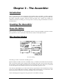
Introduction
Invoking the Assembler
From the Editor
The Control dialog
Running the assembler
Assembly Process
Return Codes
Binary file types
Types of code
Assembler Statement Format
Label field
Mnemonic Field
Operand Field
Comment Field
Expressions
Local Labels
Instruction Set
Word Alignment
Assembler Directives
Assembly Control
Assembler Directives
Repeat Loops
Listing Control
Label Directives
Floating Point Directives
Page iii
Hisoft Devpac 3
47
47
47
47
47
50
53
53
53
55
55
56
56
56
57
57
64
65
65
66
67
75
78
78
80
83
Contents
Conditional Assembly
Macro Operations
Output File Directives
Atari Executable (ATARI, L0)
GST Linkable (GST, L1)
DRI Linkable (DRI, L2)
Motorola S-records (SREC, 16)
Lattice C linkable (LATTICE, 17)
Directive Summary
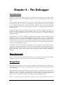
CHAPTER 4 - THE DEBUGGER
Introduction
Mon Concepts
Exceptions
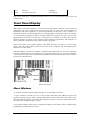
Front Panel Display
Symbolic Debugging
Mon Dialogs
Command Input
Mon Overview
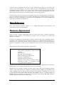
Mon Reference
Numeric Expressions
Window Types
Cursor Keys
Window Commands
Other Alt- Commands
Screen Switching
Breaking into Programs
Breakpoints
History
Quitting Mon
Loading & Saving
Searching Memory
Miscellaneous
Auto-Resident Mon
Command Summary
Debugging Stratagem
Hints & Tips
Bug Hunting
AUTO-folder programs
Desk Accessories
Page iv
84
86
92
92
94
97
98
99
102
105
105
105
105
107
108
109
109
110
112
112
114
117
118
121
122
123
123
125
126
126
129
130
135
135
137
137
137
138
138
Hisoft Devpac 3
Contents
Exception Analysis
139
CHAPTER 5 – CLINK THE LINKER
A simple CLink command line
Concepts
ALVs
Near DATA/BSS
Directives
Input directives
Output directives
Map files
Options
'WITH' files
CLINKWITH; the Clink environment variable
Reserved symbols
CLink Messages
CLink Warnings/messages
Clink Errors
CHAPTER 6 - OTHER TOOLS
S-record Splitter
Command line examples
Ramdisk
Symbol Strip Utility
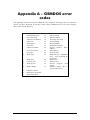
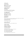
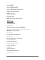
APPENDIX A - GEMDOS ERROR CODES
141
141
141
141
141
142
142
142
144
145
146
147
148
149
149
149
154
154
154
155
156
157
APPENDIX B - DEVPAC ERROR MESSAGES 158
Errors
Warnings
158
163
APPENDIX C - TOS MEMORY MAP
The Different Sorts of RAM
Processor Dump Area
Base Page Layout
Page v
Hisoft Devpac 3
165
165
165
165
Contents
Hardware Memory Map
167
APPENDIX D - GST SUPPORT
LinkST, The GST format linker
Introduction
Invoking LinkST
LinkST Running
GSTlib, The GST format librarian
168
168
168
168
169
174
APPENDIX D - CALLING THE OPERATING
SYSTEM
177
GEMDOS - Disk and Screen I/O
Program Startup and Termination
GEMDOS Summary
BIOS - Basic I/O System
XBIOS Extended BIOS
GEM Libraries
GEM AES Library
Application Library
Event Library
Menu Library
Object Library
Form Library
Graphics Library
Scrap Library
File Selector Library
Window Library
Resource Library
Shell Library
GEM VDI Library
Control Functions
Output Functions
Attribute Functions
Raster Operations
Input Functions
Inquire Functions
AES & VDI Program Skeleton
Desk Accessories
Page vi
Hisoft Devpac 3
177
178
179
190
194
208
209
210
210
211
211
212
212
213
213
214
214
214
216
216
217
218
219
220
220
221
221
Contents
Linking with AES & VDI Libraries
Menu Compiler
VT52 Screen Codes
Cookie Jar
Operating system version numbers
The OS header
Changing window colours
222
222
223
224
226
226
228
APPENDIX E - THE FLOATING POINT COPROCESSOR
229
Extended precision
Double precision
Single Precision
Packed Decimal
FPCR Floating point control register
FPSR Floating point status register
FPIAR Floating point instruction address register
229
229
230
230
231
231
232
APPENDIX F - CONVERTING FROM OTHER
ASSEMBLERS
234
Atari MadMAC
GST-ASM
MCC Assembler
K-Seka
Fast ASM
234
234
234
235
235
APPENDIX G - NEW FEATURES
Summary of Version 3 Improvements
The Editor
The Assembler
The Debugger
Integration
New tools
Features added to Devpac ST 2
APPENDIX H - TECHNICAL SUPPORT
Page vii
Hisoft Devpac 3
236
236
236
236
237
237
237
237
239
Contents
APPENDIX I -
240
BIBLIOGRAPHY
240
Atari
680x0
Algorithms & Data Structures
Page viii
Hisoft Devpac 3
240
241
242
Contents
Chapter I - Introduction
Introduction
HiSoft Devpac 3 (called simply HiSoft Devpac from now on) is a complete package for the
production of fast, efficient assembly language programs on your Atari computer.
There is an editor for the creation and editing of your assembler source code, a linker for
building your programs together with other object files, a debugger for helping you to stamp
out those nasty bugs and, of course, an assembler to turn your source code into speedy,
compact machine code.
This chapter is an introduction to this manual which aims to cover all aspects of installing and
using HiSoft Devpac on your Atari computer - it does not attempt to teach you 680x0
programming although the accompanying 68000 pocket book and the examples should be of
assistance in this regard. For further reading, you should consult the Bibliography.
Please spend some time and effort getting to know and learning how to use the manual so
that you can gain the maximum benefit from HiSoft Devpac.
The rest of this section explains how to use the manual, whether you are a beginner or an
expert, how to use your computer to best effect with HiSoft Devpac and, finally, we outline
the different type styles that we have used throughout the manual to (hopefully) make it easy
and enjoyable to use.
Devpac 3 Disk Contents
Devpac 3 is supplied on one double-sided 3.5" disk. Please note that the following list of files is
intended as a guide only; subsequent versions of Devpac may contain extra files.
DEVINST.RSC,DEVINST.PRG,DEVINST.DIR,DEVINST.INF
The installation program and its support files.
DEVPAC.PRG
The multi-window editor and control program.
HISOFTED.INF
The editor preferences file.
READ.ME
A text file including latest details about Devpac 3; please read
this file carefully before contacting our technical support
department with any queries.
AMON \
Auto-resident versions of Mon, the debugger.
Introduction
Hisoft Devpac 3
Page 9
BINXCUNK.TTP
Lattice C format linker.
BINXGEN.TTP
68000 version of Gen, the assembler.
BIN\MON.PRG
68000 version of Mon, the debugger
BINXSRSPLIT.TTP
A utility program for users of Motorola format S-records which
splits an S-record file into its high and low byte components.
BINXSTRIP.TTP
Symbol table stripper.
BIN030N
68030 specific versions of Gen, the assembler, and Mon, the
debugger.
EXAMPLES\
Some example programs including the short tutorial for this
manual.
EXTRAS\ ,EXTRAS\ AESPATH,EXTRAS\ FSEL\
A number of 'freebies'; please see the text files within these
subdirectories for more details.
EXTRAS\MENU2ASM\
Devpac 2 compatible menu compiler.
INCDIR\AESUB.S
AES library source.
INCDIR\BIOS.I
BIOS definitions include file.
INCDIRXGEMDOS.I
GEMDOS definitions include file.
INCDIRXGEMMACRO.I
macros for AES/VDI interface.
INCDIRWDIUB.S
VDI library source.
INCDIRXXBIOS.I
XBIOS definitions include file.
GST\
GST linker, librarian and library files.
RAMDISK\
Reset-proof ramdisk and associated files.
Making a Working Copy
Before using Devpac 3 you should make a back-up copy of the distribution disk and put the
original away in a secure place; safe from extremes of temperature, magnetic fields, moisture
and children! The disks can be backed-up using the Desktop or any backup utility - before
making any backup always write-protect the master to prevent accidental erasure.
The disk is not copy-protected to allow easy back-up and to avoid inconvenience; remember
though that the software and this manual are protected by international copyright laws and
you are only permitted to copy the software for your own personal use. If this sounds
officious, look at it another way - if you give away copies of Devpac 3 to your friends we will
not receive enough revenue from the sale of the package to improve this and other products.
We want to help you, please help us in return.
Introduction
Hisoft Devpac 3
Page 10
Registration Card
Enclosed with this manual is a registration card which you should fill in and return to us in
order to register your purchase of Devpac 3. This will entitle you to a free period of technical
support and will enable us to keep you informed of future developments to our software.
For details of our technical support services, please refer to Appendix H in this manual.
You will need to quote your serial number (to be found on the disk label) to obtain technical
support and you may find it useful to make a note of it here:
Serial No.
The README File
As with all HiSoft products Devpac 3 is continually being improved and the latest details that
cannot be included in this manual may be found in the READ.ME file on the disk. This file
should be read at this point, by double-clicking on its icon from the Desktop. It will also
contain last-minute details on the installation process.
Installation
Whether you are a beginner or expert you should now run the installation program from
your back up copy of the distribution disk. The GEM-based installation program is designed
to ease the building of various standard configurations for the HiSoft Devpac system.
For hard disk owners, the installation program will copy the files that you need to your hard
disk. If you are the type of person who doesn't like installation programs that write things to
your hard disk, you can view the files that would be copied, and copy them yourself. The
installation takes note of your hardware configuration and only copies files that could be of
use to you.
By default, the installation program (for floppy based installations) doesn't copy the tools for
using the GST format as most people don't need this.
The installation program for hard disk users deliberately does not automatically install a
ramdisk. This is because many users will already have their own preferred ramdisk.
For users of floppy disk based systems, the installation program will produce a work floppy
which contains the essential tools for your machine configuration, this disk can also be used
to keep small programs of your own.
If you are using a non-hard disk system and wish to use larger than normal capacity (e.g.
800K) floppy disks, you should format a floppy using your favourite extended formatter prior
to running the installer; you must use the volume name DEVWORK for this disk. If you
intend to use standard floppies then the installation program will format these for you.
Introduction
Hisoft Devpac 3
Page 11
We strongly suggest that you start by using the set-up recommended by the installation
program until you are sufficiently familiar with the package to re-configure it to meet your
unique requirements.
To run the installation program, double-click on DEVINST.PRG from your backup of disk 1
in Drive A. Note that the installer expects to find its subsidiary files in the current directory.
How to use the Manual
We have designed this manual to tell you about using HiSoft Devpac on the Atari computers.
We have packed a great deal of information about the package into the manual and, in order
to help you use it efficiently and easily, we will now plot recommended courses through the
manual, whether you are a beginner to assembly language or a seasoned expert.
A Course for the Beginner
If you are a newcomer to assembly language then we recommend that you read one of the
books in the Bibliography alongside this manual.
This chapter is an introduction to using Devpac and covers the contents of your master disk,
making a back-up copy of it, installing Devpac and registering your purchase.
At the end of this chapter there is a simple tutorial which you should follow to familiarise
yourself with the use of the main parts of the program suite; it is certainly worth working
through.
Chapter 2 considers the editing environment with an overview of using the package and is
well worth reading; much of Chapter 3, detailing the assembler, is liable to mean little until
you become more experienced but should be used as a reference. The overview of the
debugger in Chapter 4 is recommended, though the detail of this package can be left for a
while. Chapters 5 and 6 can be omitted unless you are linking your programs together or using
S-records. Looking at and running the supplied source code should be helpful.
The Appendices are mainly for reference and you will only need to dip into them
occasionally.
We hope you find HiSoft Devpac easy and friendly to use, please do not hesitate to write to
us with any suggestions for improvements and/or alterations.
A
Course
for
Programmers
Seasoned
Assembler
If you are experienced in the use of 680x0 assembly language but have not used a member of
the Devpac family before then here is a very quick way of assembling a source file:
Load DEVPAC.PRG, Press Alt-L and select your file which will load into the editor. Using the
first four entries on the Options menu select the options you require. You should also select
Format - ST RAM from the Assembler options - Control dialog.
Pressing Alt-A will start the assembler; any assembly errors will be remembered and on
Introduction
Hisoft Devpac 3
Page 12
return to the editor you will be placed on the first one. Subsequent errors may be found by
pressing Alt-J.
To run your successfully-assembled program press Alt-X (note that the Run command this is
available whether assembling to disk or memory).
As a quick introduction to the debugger the example at the end of this preface is
recommended. If you have any problems please read the relevant section of the manual before
contacting us for technical support.
The Appendices are for general reference and it is worth glancing through all of them to
acquaint yourself with their contents.
Good luck, we hope you find HiSoft Devpac a powerful, flexible and easy-to-use
development system. Of course, we welcome any written comments you may have on how
we might improve both the program and the manual.
Devpac Version 2 Users
Turn to Appendix F and read the section summarising the new features, then read Chapter 2
which covers the editor. The beginning of Chapter 3 covers the new assembly options.
System Requirements
HiSoft Devpac will run on any Atari 680x0 computer (ST, STE, Mega, TT, Falcon etc.) with at
least 512Kb of memory and a double-sided disk drive. You will undoubtedly find it useful for
this and other programs to purchase a second disk drive or hard disk.
Users with only 512Kb of RAM may run out of memory when attempting to assemble larger
programs or in other circumstances. The installation of a RAM-disk or other device on a
512Kb machine will restrict HiSoft Devpac.
If you are short of memory, remember that the least memory hungry thing is to assemble a
one line program (consisting of an include statement) from a CLI. Upgrades to a megabyte of
memory are available at very reasonable prices and we strongly recommend this, not just for
HiSoft Devpac but for general use too.
Typography
In order to make the manual easy to read and to convey the maximum information as clearly
as possible, we have adopted certain typefaces and type styles throughout the manual.
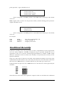
Typefaces
Palatino
Introduction
General text.
Hisoft Devpac 3
Page 13
Futura oblique
Chapter and sub-Chapter headings and
Monospace
Used to show something that is typed in at
the keyboard or displayed on the screen.
Predominantly used in program listings and
references to function
names, variables etc.
Avant Garde
Used for filenames, menu selections
and button names. Also used to
denote legends on single keys such as Alt
(the Alternate key) and Control.
Type styles
The italic style is used mainly for emphasis.
Special Characters
[]
Within syntax descriptions, information enclosed in [ ] is
optional.
Indicates repetition in syntax descriptions.
Vertically-spaced dots show that some part of a program has been omitted.
Acknowledgements
The trademarks (both registered and otherwise)
throughout this manual. In particular:
of various companies are used
HiSoft Devpac, Power BASIC, HiSoft BASIC, Gen and Mon are trademarks of HiSoft
Atari is a registered trademark of Atari Corp.
We acknowledge any other trademark used but not listed above.
We would like to thank the following people for their invaluable help in the production of
HiSoft Devpac and this manual:
Andy Pennell for his hard work in programming the original Devpac, Julia for holding the
fort when lesser people would have deserted, Marlynne for her tenaciousness and tact, Sallie
for her database work and her jodhpurs, Pauline for getting it together and all the other
unsung heroes and heroines that have kept us alive and smiling over the past 12 years!
Introduction
Hisoft Devpac 3
Page 14
A Quick Tutorial
This is deliberately a 'quick and dirty' tutorial so you can see how straightforward it is to
create, edit, assemble and debug programs with Devpac.
In this tutorial we are going to assemble and run a simple program, which contains two
errors and debug it. The program itself is intended to print a message.
To follow this tutorial you must already have installed Devpac and be in the editor. If you are
not you should run the installation program (assuming you have not already done so), then
double-click on the DEVPAC.PRG icon from your work disk.
You will then be presented with an empty window; to load the file you should move the
mouse over the File menu and click on Load.... The standard GEM file selector will then
appear and the file we want is called DEMO.S. You may either double-click on the name or
type it in and press Return to load the file. Note that the file is in the EXAMPLES directory on
your work disk.
When the file has loaded the window will show the top lines of the file. If you want to have a
quick look at the program you may click on the scroll bar or use the cursor keys.
With most shorter programs it is best to have a trial assembly that doesn't produce a listing or
binary file to check the syntax of the source and show up typing errors and so on. Move the
mouse to the Program menu and select Check.
The assembler will report an error, instruction not recognised, pressing any key will return
you to the editor. The cursor will be placed on the incorrect line and the error message
displayed in the window title bar.
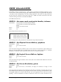
The program line should be changed from MOV. L to MOVE . L, so do this, then select
Control... from the Options menu and change the setting of the Format popup menu to ST
RAM. This is very much faster than assembling to disk and allows you to try things out
immediately, which is exactly what we want.
If you are unsure of how any of the user interface elements work, you may like to
read the section A word about pop-up menus and dialogs now.
The assembly worked this time, so click on Run from the Program menu, and what happens?
Not a lot it would seem, except that some bombs appeared briefly on the screen - oh, there's a
bug.
Some alternate desktops (e.g. NeoDesk™) and other programs (e.g. MiNT) replace
the standard bomb handler; in this case you won't see bombs, but that program's
'bomb' handlers message...
The tool for finding bugs and checking programs is a debugger, so select Debug from the
Program menu which will call the debugger. This is described more fully later, but for now
we just want to run the program from the debugger to 'catch' any problems and find out what
causes them, so press Control-R to run the program.
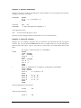
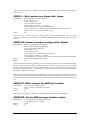
On a 68000 computer, the message Address Error will appear at the bottom of the display,
Introduction
Hisoft Devpac 3
Page 15
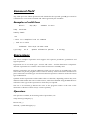
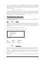
with the Disassembly window showing the current instruction
MOVE.W
1,-(A7)
This instruction causes an address error on a 68000 because the location 1 is at an odd address
which cannot be accessed with the MOVE.W instruction.
This is not the case on 68020s upwards and, you will instead see the message Bus Error, but
with the Disassembly window showing the same instruction. In this instance the problem is
because location 1 is in protected memory which cannot be accessed in user mode.
However, for all processors, the problem is the same - there should a hash sign before the 1 to
put the immediate value of 1 on the stack. To return to the editor press Control-C twice (once
to terminate your program, once to terminate the debugger), so we can fix this bug in the
source code.
Press Alt-T, to go to the top of the file, then click on Find from the Search menu. We are going
to find the errant instruction so enter:
move.w
then press Return to start.the search. The first occurrence has a hash sign, so press Alt-N to
find the next, which is the line:
move.w
c_conin,-(a7)
Ahah! - this is the one, so add a hash to change it to
move.w
#c_conin,-(a7)
then assemble it again. If you click on Run from the Program menu you should see the
message, and pressing any key will return you to the editor.
However, did you notice how messy the screen was - the desktop pattern looked very untidy
and you possibly got mouse 'droppings' left on the screen. This was because DEMO is a TOS
program running with a GEM screen - to change this, click on Run with GEM from the
Program menu - the check mark next to it should disappear. If you select Run again you can
see the display is a lot neater, isn't it? If you run a GEM program you must ensure the check
mark is there beforehand, otherwise nasty things can happen.
Although the program now works we shall use Mon, the debugger, to trace through the
program, step by step. To do this select Debug from the Program menu, the debugger will
appear with the message Breakpoint, showing your program.
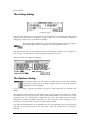
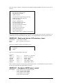
There are various windows, the top one displaying the machine registers, the second a
disassembly of the program, and the third some other memory.
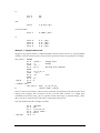
If you look at window 2, the Disassembly window, you will see the current instruction, which
in this case is
MOVE.L
#string,-(A7)
As the debug option was specified in the source code all program symbols will appear in the
debugger.
Let's check the area around string. Press Alt-3 and you should see window 3's title inverted.
Introduction
Hisoft Devpac 3
Page 16
Next press Alt-A and a dialog box will appear, asking Window start address? - to this enter
string
and press Return. This will re-display window 3 at that address, showing the message in both
hex and ASCII.
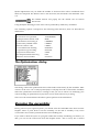
To execute this MOVE instruction press Control-Z. This will execute the instruction then the
screen will be updated to reflect the new values of the program counter and register A7. If
you press Control-Z again the MOVE.W instruction will be executed. If you look at the hex
display next to A7 you should see a word of 9, which is what you would expect after that
instruction.
The next instruction is TRAP #1, to call GEMDOS to print a string, but hang on - would we
notice a string printed in the middle of the Mon display? Never fear, Mon has its own screen
to avoid interference with your program's, to see this press the V key, which will show a
blank screen, ready for your program. Pressing any other key will return you to Mon.
To execute this call press Control-Z, which will have printed the string. To prove it press V
again, then any key to return to Mon.
Press Control-Z twice more until you reach the next trap. This one waits for a key press so hit
Control-Z and the program display will automatically appear, waiting for a key. When you're
ready, press the q key. You will return to Mon and if you look at the register window the low
8 bits of register DO should be $71, the ASCII code for q, and next to that it will be shown as q
(unless in low-resolution).
The final trap quits the program, so to let it run its course press Control-R, you will then
return to the debugger as the program has finished. Finally press Control-C to leave the
debugger and return to the editor.
That completes our quick tutorial.
Introduction
Hisoft Devpac 3
Page 17
Chapter 2 - Using the Editor
Introduction
The editor supplied with HiSoft Devpac is fully integrated with the system which means that
you can develop programs in an intuitive and interactive manner, creating and editing your
programs in the same environment as running and debugging your finished masterpiece.
Moreover, those of you with strong preferences for your own editor can dispense with the
HiSoft editor and use your own favourite package along with the command line version of
HiSoft Devpac; although you will lose the benefits of interactive development.
The editor for HiSoft Devpac is a multi-window screen editor which allows you to enter and
edit text and save and load from disk, as you would expect. It also lets you print some or all
of your text, search and replace text patterns and use any of your computer's deskaccessories. It is GEM-based, which means it uses all the user-friendly features of GEM
programs that you have become familiar with such as windows, menus and mice. However,
if you're a diehard used to the hostile world of computers before the advent of WIMPs, you'll
be pleased to know you can do practically everything you'll want to do from the keyboard
without having to touch a mouse.
The editor is 'RAM-based', which means that the file you are editing stays in memory for the
whole time, so you don't have to wait while your disk grinds away loading different sections
of the file as you edit. As the ST/TT range of computers have so much memory, the size
limitations often found in older computer editors do not exist with HiSoft Devpac. As all
editing operations, including things like searching, are RAM-based they act extremely
quickly.
When you have typed in your programs it is not much use if you are unable to save them to
disk, so the editor has a comprehensive range of save and load options, allowing you to save
all or part of the text and to load other files into the middle of the current one, for example.
To get things to happen in the editor, there are various methods available to you. Features
may be accessed in one or more of the following ways:
Using a single key, such as a Function or cursor key;
Clicking on a menu item, such as Save;
Using a menu shortcut, by pressing the Alternate key (subsequently referred to as Alt) in
conjunction with another, such as Alt - F for Find;
Using the Control key in conjunction with another, such as Control -A for cursor word left,
Clicking on the screen, such as in a scroll bar.
The menu shortcuts have been chosen to be, hopefully, easy to remember.
A word about pop-up menus and dialogs
The editor makes extensive use of dialog boxes and pop-up menus, so it is worth recalling
The Editor
Hisoft Devpac 3
Page 18
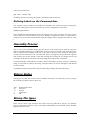
how to use them, particularly for entering text. The editor's dialog boxes contain buttons,
radio buttons, and editable text.
Exit buttons may be clicked on with the mouse and cause the dialog box to go away. Usually
there is a default button, shown by having a wider border than the others. Pressing Return on
the keyboard is equivalent to clicking on the default button. Where there are non-default
buttons, the editor allows these to be selected from the keyboard using the sequence Alt-first
letter of the button name; obviously where several buttons have the same first letter only one
may be selected!
Radio buttons are groups of buttons of which only one may be selected at a time - clicking on
one automatically de-selects all the others.
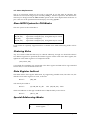
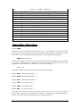
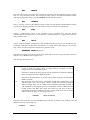
A dialog with buttons (OK, Cancel) and radio buttons (Normal, Small etc.)
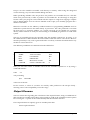
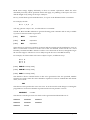
Editable text is shown with a dotted line, and a vertical bar marks the cursor position.
Editable text
Characters may be typed in and corrected using the Backspace, Delete and cursor keys. You
can clear the whole edit field by pressing the Esc key. If there is more than one editable text
field in a dialog box, you can move between them using the Tab key or the j and | keys or by
clicking near them with the mouse.
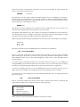
More than one editable text field
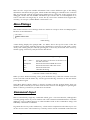
Some dialog boxes allow only a limited range of characters to be typed into them - for
example the Goto... dialog box only allows numeric characters (digits) to be entered.
As well as the conventional GEM user interface facilities, the editor also uses some extensions.
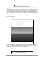
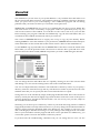
To illustrate these, consider the dialog box shown below:
The Editor
Hisoft Devpac 3
Page 19
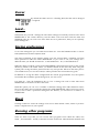
The Tool Configuration dialog box
Some options are accessed via 'pop-up' menus similar to those used by Atari's new control
panel. Thus if you move the mouse over the As shown selection (by Command line) and
press down on the left mouse button, a menu like this will pop up:
A pop-up menu
This indicates that the current setting for this option is As shown. The mouse will highlight
the current selection that you are making and when you let go of the mouse this indicates that
you have made your selection. If you let go outside the pop-up menu then this is taken as
cancelling the selection.
The box beside Make resident has a cross in it, indicating that this option is selected; similarly
Report all errors is not selected. Clicking in one of these boxes, or the associated text, will
cause that option to be toggled on and off.
Run as TOS and Run as GEM are a pair of 'radio options'; the solid box indicates the currently
selected item: clicking on Run as TOS will change both boxes.
Some of the menu items on the main 'drop-down' menus now have submenus; these are
indicated by a o symbol. For example:
A sub menu
When you highlight a menu item (like Arrange Windows in the example above), the
corresponding sub-menu will appear after a short delay. You can then move the mouse to the
right to select the particular item that you want. To cancel the operation just click outside both
boxes without selecting an item or move to another item from the main menu.
If the editor doesn't have enough room to display the sub-menu to the right of the main
menu, it will do so on the left; the items are selected in the same way.
The editor also uses a number of list boxes; these allow a number of selections to be entered
(e.g. multiple INCLUDE directories, EQU symbols etc.).
A list box
The Editor
Hisoft Devpac 3
Page 20
To add a new element to the list, click on the Add button, whilst an existing element may be
removed by clicking on the item (which will become highlighted) and then clicking Remove.
To edit an existing item, double-click on it. If at some point you need to reorder the entries in
the list (e.g. the order in which INCLUDE directories are searched), this may be achieved by
dragging an entry from its current position to a new position.
The Editor
Hisoft Devpac 3
Page 21
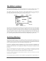
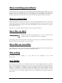
The Editor's windows
Having loaded HiSoft Devpac, you will be presented with an empty window with a status
line at the top and a flashing black block, which is the cursor, in the top left-hand corner.
The window used by the editor works like all other GEM windows, so you can move it
around by using the title bar on the top of it, you can change its size by dragging on the grow
box, and make it full size (and back again) by clicking on the full box.
A GEM window
The status line contains information about the cursor position in the form of Line and Column
offsets as well as the number of bytes of memory which are free to store your text. Initially
this is displayed as 59980, as the default text size is 60000 bytes. You may change this default
if you wish, together with various other options, by selecting Preferences, described later. The
'missing' 20 bytes are used by the editor for internal information. The rest of the status line
area is used for error messages, which will usually be accompanied by a 'ping' noise to alert
you. Any message that is printed will be removed when subsequently you press a key.
Switching Windows
The editor has support for up to seven windows, which can be selected by pressing Alt-1 to
Alt-7 (on the top row of numbers, not on the numeric pad). The windows can be organised in
a number of ways and you can select this using Arrange Windows on the Edit menu. Try this
out for yourself to get the idea of how the different arrangements work.
If you have a preferred window arrangement, you can get the editor to remember your
preference by holding down Control whilst selecting the layout. The layout will then become
permanent and the editor will rearrange the windows as necessary to conform to your
preference.
You can cycle through the open windows using the Cycle Windows command from the Edit
menu (or use Control-V), by clicking on the appropriate window with the mouse or by
selecting the appropriate sub-item from the Window item on the Edit menu.
To close a window and thus free the memory used by it, click on its close box or use the
Control-W key combination.
To cut and paste between windows is just as simple as copying blocks in a single window, i.e.
The Editor
Hisoft Devpac 3
Page 22
mark the block and then use the Cut command, switch windows (as described above) and
then Paste. See below for more detail on cut and paste.
Entering text and moving the cursor
To enter text, simply type on the keyboard and at the end of each line press the Return key (or
the Enter key on the numeric pad) to start the next line. You can correct your mistakes by
pressing the Backspace key, which deletes the character to the left of the cursor, or the Delete
key, which removes the character on the cursor.
Cursor keys
To move the cursor around the text to correct errors or enter new
characters, you can use the cursor keys, labelled *
» | and j or the
mouse; move the cursor to a specific position on the screen with the mouse pointer and click.
If you position the cursor past the right-hand end of the line and type some text at that point
the editor will automatically add the text to the real end of the line. If you type in long lines
the window display will scroll sideways if required.
When you cursor up at the top of a window the display will either scroll down if there is a
previous line, or print the message Top of file in the status line. Similarly if you cursor down
off the bottom of the window the display will either scroll up if there is a following line, or
print the message End of file.
You can move the cursor on a character basis by clicking on the arrow boxes at the end of the
horizontal and vertical scroll bars.
To move immediately to the start of the current line, press Control *-, and to move to the end
of the current line press Control -*.
To move the cursor a word to the left, press Shift«- and to move a word to the right press
Shift -». You cannot move past the end of a line with Shift -». A word is defined as anything
surrounded by a space, a tab or a start or end of line. The keys Control-A and Control - F also
move the cursor left and right on a word basis.
To move the cursor a page up, you can click on the upper grey part of the vertical scroll bar,
or press Shift f. To move the cursor a page down, you can click on the lower grey part of the
scroll bar, or press Shiftj.
Tab key
The Tab key inserts a special character (ASCII code 9) into the buffer, which on the screen
looks like a number of spaces, but is rather different. Pressing Tab aligns the cursor onto the
next 'multiple of 8' column, so if you press it at the start of a line (column 1) the cursor moves
to the next multiple of 8, +1, which is column 9. Tabs are very useful indeed for making items
line up vertically such as the instructions in your program. When you delete a tab the line
closes up as if a number of spaces had been removed. The advantage of tabs is that they take
up only 1 byte of memory, but can show on screen as many more.
The Editor
Hisoft Devpac 3
Page 23
You can change the tab size using the Preferences command described shortly.
Backspace key
The Backspace key removes the character to the left of the cursor. If you backspace at the very
beginning of a line it will remove the 'invisible' carriage return and join the line to the end of
the previous line. Backspacing when the cursor is past the end of the line will delete the last
character on the line, unless the line is empty in which case it will re-position the cursor on
the left of the screen.
Delete key
The Delete key removes the character under the cursor and has no effect if the cursor is past
the end of the current line.
The Edit menu
The commands on the top of the Edit menu may be used to perform
the conventional Cut, Copy and Paste operations on marked blocks.
These are described under Block commands, below.
Go to top of file
To move to the top of the text, click on Goto Top from the Edit menu, or press Alt-T. The
screen will be re-drawn if necessary starting from line 1.
Go to end of file
To move the cursor to the start of the very last line of the text, click on Goto Bottom, or press
Alt-B.
Goto line
To move the cursor to a specific line in the text, click on Goto... from the Edit menu, or press
Alt-G. A dialog box will appear, allowing you to enter the required line number. Press Return
or click on the OK button to go to the line or click on Cancel to abort the operation. After
clicking on OK the cursor will move to the specified line, redisplaying if necessary, or give the
error End of file if the line doesn't exist.
Another fast way of moving around the file is by dragging the slider on the vertical scroll bar,
The Editor
Hisoft Devpac 3
Page 24
which works in the usual GEM fashion.
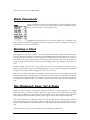
Block Commands
A block is a marked section of text which may be copied to another section,
deleted, printed or saved onto disk. Blocks may be marked using the
mouse, via menu items or with function keys.
A marked block is highlighted by showing the text in reverse. While you are editing a line
that is within a block this highlighting will not be shown but will be re-displayed when you
leave that line or choose a command.
Marking a block
The simplest way to mark a block is to click on the first character in the block and drag the
mouse to the end of the block. The block will be highlighted by showing the text in reverse as
you drag the mouse. When you move the mouse to the bottom of the window, the window
will scroll. Conversely, moving the mouse to the top of the window, will cause the window to
scroll in the opposite direction. You may start marking a block, by clicking at the end if you
wish.
Double-clicking will cause the word 'under' the mouse to be marked as the block. If you
double-click and then drag, text will be highlighted a word at a time. Clicking in the left hand
margin of the window causes dragging to occur a line at a time.
The start of a block may also be marked by moving the cursor to the required place and
selecting Block Start or pressing key F1. The end of a block can be marked by moving the
cursor and selecting Block End or pressing key F2. The start and end of a block do not have to
be marked in a specific order - if it is more convenient you may mark the end of the block
first.
The Clipboard: Copy, Cut & Paste
HiSoft Devpac provides conventional clipboard facilities, as popularised by the Apple
Macintosh. Once you have marked a block you may copy it to the clipboard by selecting
Copy from the Edit menu. The main text will remain as it is. The contents of the clipboard
may then be inserted at another position by moving the cursor there and selecting Paste.
The current block may be deleted using Cut from the Edit menu; selecting Paste will then
insert the block that was cut (unless you have used Copy in the mean time). Thus to move a
block with this method, Cut the block from its original position and then Paste it into its new
one.
The block menu also gives you the flexibility of the following commands.
The Editor
Hisoft Devpac 3
Page 25
Saving a block
Once a block has been marked, it can be saved by clicking on Save Block from the Block menu
or by pressing key F3. If no block is marked, the message What blocks ! will appear. If the
start of the block is textually after its end the message Invalid block! will appear. Both errors
abort the command. Assuming a valid block has been marked, the GEM file selector will
appear, allowing you to select a suitable disk and filename. If you save the block with a name
that already exists the old version will be overwritten - no backups are made with this
command.
Copying a block
A marked block may be copied, memory permitting, to another part of the text by moving the
cursor to where you want the block copied and clicking on Copy Block or by pressing key F4.
If you try to copy a block into a part of itself, the message Invalid block! will appear and the
copy will be aborted.
Deleting a block
A marked block may be deleted from the text by clicking on Delete Block or by pressing ShiftF5. The shift key is deliberately required to prevent it being used accidentally. A deleted block
is remembered, memory permitting, in the clipboard, for later use. This is equivalent to Cut
on the Edit menu.
Copy block to block buffer
The current marked block may be copied to the block buffer, memory permitting, using
Remember Block or by pressing Shift-F4. This can be very useful for moving blocks of text
between different files by loading the first, marking a block, copying it to the block buffer
then switching to another window or loading the other file and pasting the block buffer into
it. This is equivalent to Copy on the Edit menu.
Pasting a block
A block in the clipboard may be pasted at the current cursor position by clicking on Paste
Block or by pressing F5. This is equivalent to Paste on the Edit menu.
The contents of the clipboard is lost if the edit buffer size is changed and after an
assembly.
Printing a block
A marked block may be sent to the printer by clicking on Print Block or by pressing Alt-W.
An alert box will appear confirming the operation and clicking on OK will print the block.
The Editor
Hisoft Devpac 3
Page 26
The printer port used will depend on the port chosen with the Control Panel, or will default
to the parallel port. Tab characters are sent to the printer as a suitable number of spaces, so
the net result will normally look better than if you print the file from the Desktop.
If you try to print when no block is marked at all then the whole file will be
printed.
Block markers remain during all editing commands, moving where necessary, and are only
reset by the commands Delete block and Load.
Deleting text
Delete line
The current line can be deleted from the text by pressing Control - Y.
Delete to end of line
The text from the cursor position to the end of the current line can be deleted by pressing
Control - Q.
UnDelete Line
When a line is deleted using either of the above commands it is preserved in an internal
buffer, and can be re-inserted into the text by pressing Control - U, or the Undo key. This can
be done as many times as required, particularly useful for repeating similar lines or swapping
individual lines over.
Delete block
A marked block may be deleted from the text by clicking on Delete Block or by pressing ShiftF5. The shift key is deliberately required to prevent it being used accidentally. A deleted block
is remembered, memory permitting, in the clipboard, for later use. This is equivalent to Cut
on the Edit menu.
Searching and Replacing Text
The commands on the Search menu may be used for finding and perhaps
replacing existing text. The strings involved are set up by selecting Find or
press Alt-F.
This allows you to enter the find and replace strings as shown in the
following dialog box:
The Editor
Hisoft Devpac 3
Page 27
In the example above TextWindows has been entered as the find string and MyWindow as
the replace string.
If you click on Cancel, no action will be taken; if you click Next (or press Return) the search
will start forwards, while clicking on Previous will start the search backwards. If you do not
wish to replace, leave the replace string empty.
If the search is successful, the screen will be re-drawn with the cursor positioned at the start
of the string. If the string could not be found, the message Not found will appear in the status
area and the cursor will remain unmoved.
Whether test is treated as the same as TEST or Test etc. depends on which Casing button is
selected. In the example above the search would stop if TEXTWINDOWS was found; if
testoTest was selected then the search would not find TEXTWINDOWS.
To find the next occurrence of the string click on Find Next from the Edit menu, or press AltN. The search starts at the position just past the cursor.
To search for the previous occurrence of the string click on Find Previous from the Search
menu, or press Alt-P. The search starts at the position just before the cursor.
Having found an occurrence of the required text, it can be replaced with the replace string by
clicking on Replace from the Search menu, or by pressing Alt-R. Having replaced it, the editor
will then search for the next occurrence.
If you wish to replace every occurrence of the find string with the replace string from the
cursor position onwards, click on Replace All from the Search menu. During the global
replace the Esc key can be used to abort when the status area will show how many
replacements were made. There is deliberately no keyboard equivalent for Replace All to
prevent it being chosen accidentally.
To search and replace Tab characters press Control-1 when typing in the dialog box. Other
control characters may be searched for in a similar manner except for the CR (Control-M) and
LF (Control-J) characters. Alternatively, press Shift-Ins and this will display the character set
from which you may pick the required character with the mouse.
Bookmarks
A further way to navigate your source text is via the use of bookmarks. A bookmark is set by
selecting the appropriate Set Bookmark item from the Search menu or by using Control-Shift
and a digit key (not the numeric keypad). When you set a bookmark the corresponding item
on the Goto Bookmark menu will become enabled. Then, selecting this item, or by pressing
Control and the digit, will return you to the original position.
The Editor
Hisoft Devpac 3
Page 28
When you set a bookmark, the window number to which it refers is displayed in the menu.
Going to a bookmark may cause you to switch windows. Note that bookmarks that are set in
a given window are lost when you close that window.
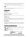
Disk Operations
The File menu contains many operations that involve using the disk
system; you can save and load your source file, insert text into your source,
delete a file from a disk and more.
New
Select New to open an empty window, assuming that there is one available - you are allowed
up to seven windows at once in HiSoft Devpac.
Assuming that there are no more than six windows open, New will create a window which is
empty and has no title.
Loading Text
To load in a new text file, click on Load from the File menu, or press Alt-L. This will open a
new window (or warn you if no more windows are available) or select an unused window
and then a file selector will appear, allowing you to specify the disk and filename. Assuming
you do not Cancel, the editor will attempt to load the file. If it will fit, the file is loaded into
memory and the new window is re-drawn. If it will not fit an alert box will appear warning
you, and you should use Preferences to make the edit buffer size larger, then try to load it
again.
If the file can't be found a dialog box will appear, asking you if you wish to create that file.
You may do so, or alternatively modify the filename and try again.
When loading HiSoft Devpac from a CLI, you may include up to seven filenames. The
corresponding files will then be loaded automatically. If a file cannot be found you will be
asked if you wish to create it or may change the filename if you wish. If you use the new Atari
desktop (TOS 2.00 and above) and install HiSoft Devpac as a GEM takes parameters (GTP)
program then you may also enter up to seven file names to be loaded.
Revert
Revert will warn you that you are about to lose the text in the selected window and, assuming
The Editor
Hisoft Devpac 3
Page 29
that you choose to continue, it will then re-load the last saved version of the file that you were
editing in this window.
Revert will do nothing if you try to use it on a file that has not been saved previously.
Save As...
To save the text you are editing, click on Save As... from the File menu, or press Alt-S. The file
selector will appear, allowing you to select a suitable disk and filename. Clicking OK or
pressing Return will then save the file onto the disk.
If you click on Cancel the text will not be saved. Normally if a file exists with the same name
it will be deleted and replaced with the new version, but if Make backups is selected from
Preferences then any existing file will be renamed with the extension .BAK (deleting any
existing .BAK file) before the new version is saved.
Save
If you have already done a Save As (or a Load), the editor will remember the name of the file
and display it in the title bar of the window. If you want to save it without having to bother
with the file selector, you can click on Save on the File menu, or press Shift-Alt-S, and it will
use the old name and save it as above. If you try to Save without having previously specified
a filename you will be presented with the file selector, as in Save As.
Inserting Text
To read a file from disk and insert it at the current position in your text, click on Insert File
from the File menu, or press Alt-1. The file selector will appear and assuming that you do not
cancel, the file will be read from the disk and inserted, memory permitting.
Delete File
You may want to delete a file from disk (if for instance you have run out of disk space whilst
trying to save); click on Delete File. The file selector will appear, allowing you to select a
suitable disk and filename. Clicking OK or pressing Return will then delete the file from the
disk. If you click on Cancel the file will not be deleted.
Close
This is the same as pressing Control-W and will close the currently selected window. If the file
that is being edited in this window has been changed since it was loaded or is a new file, you
will be warned before the window is closed. You can choose to continue and lose your
changes, cancel the action or save the changes.
The Editor
Hisoft Devpac 3
Page 30
Change Directory
This option allows you to move the current directory path; this can be useful when running
programs which expect all of their files to be in the same place as the program itself. After
clicking on Change Directory the file selector will appear, allowing you to select a suitable
disk and folder name. Clicking OK or pressing Return will then change the directory. If you
click on Cancel the directory path will not be changed.
Quitting HiSoft Devpac
To leave HiSoft Devpac, click on Quit from the File menu, or press Alt-Q. If changes have been
made to the text which have not been saved to disk, an alert box will appear asking for
confirmation.
This example shows that two files have changed. Clicking on Save All, As Above or pressing
Return will exit the editor saving the changes. Clicking on Cancel will return to the editor.
Leave All will ignore all the changes you have made.
If you wish to save some files but not others click on the appropriate Leave buttons. For
example if you clicked on the Leave button by ASASMTXT.S in the above example and then
pressed Return, only RASM3.S and CASETAB.S would be saved.
You can also enable and disable backups from this dialog box. This is useful if you normally
use backups, but decide that you don't require a backup of a one line change.
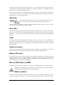
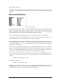
Configuring the editor
Selecting Preferences… from the Options menu will produce a dialog box like this:
The editor preferences box
The Editor
Hisoft Devpac 3
Page 31
This box allows you to set up the editor as you would like to use it; you can then save your
customisation to disk so that the editor will always behave the same way. Here are the
different settings that you can change.
Auto-indent lines
Selecting this option sets auto-indent mode. When active, an indent is added to the start of
each new line created when you press Return. The contents of the indent of the new line is
taken from the white space (i.e. tabs and/or spaces) at the start of the previous line. This
allows you to lay out your program neatly, by simply pressing Return.
Auto-save configuration
When this option is selected, the current preferences will automatically be saved when you
exit the editor. So when you load the editor again, the preferences will be just the same as
when you last used it.
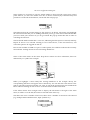
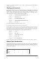
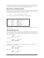
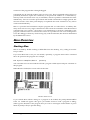
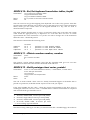
Cursor mode numeric pad
The Cursor Mode Numeric Pad option allows the use of the numeric keypad in an IBM-PClike way allowing single key presses for cursor functions, and defaults to Cursor pad mode.
The keypad works as shown in diagram below:
When this option is not selected the keyboard reverts to returning the digits etc.
Hide mouse when typing
Selecting Hide mouse when typing causes the mouse pointer to disappear when you start
entering text with the keyboard. As soon as you move the mouse, or use a command that
displays a dialog box, the mouse will re-appear. This option may be disabled if you prefer to
always see the mouse on the screen.
Make backups
Selecting this option causes the editor to make a backup (with the extension .BAK) when
saving files.
The Editor
Hisoft Devpac 3
Page 32
Show matching parentheses
This facility lets you check that your parentheses match. With this option enables, when you
press ) the cursor will quickly move to any matching ( character and then back to the current
position, thus you can ensure that you have closed the correct number of brackets in a
complex expression. If you find this cursor movement distracting then disable the option.
Stop at end of line
When this option is selected, if you press cursor left at the beginning of a line or cursor right
at the end of line, the cursor does not move. Disabling this option, causes the cursor to move
to the previous line if you press cursor left at the beginning, and to the next line if you press
cursor right at the end.
The best way to find out which you prefer is to try using each setting.
Save files on Quit
By default the editor will prompt you, if you are about to quit
without having saved all the files, you have changed.
The saving of these files can be made automatic by selecting Yes or disabled by selecting No
(but don't blame us if you forget to save your files!).
Save files on run other
This enables you to choose whether files are saved before using the Run Other and Run with
Shell commands, in the same way as that for Save files on Quit.
Tab setting
By default,
from 2 to 16.
the
tab
setting
is
8,
but
this
may
be
changed
to
any
value
Text Buffer
By default the text buffer size is 60000 bytes, but this can be changed from 4000 to 999000
bytes. This determines the largest file size that can be loaded and edited. This amount of
memory is allocated for each window in use. Care should be taken to leave sufficient room in
memory for assemblies - pressing the Help key displays free system memory, and for
assemblies this should always be at least 100k bytes. Changing the editor workspace size will
cause any text you are currently editing to be lost, so a confirmation is required if it has not
been saved.
The Editor
Hisoft Devpac 3
Page 33
Cursor
By default the editor cursor is a flashing block, but this can be changed
as required.
Load...
This button lets you load a settings file. The editor settings are normally stored in a file called
HISOFTED.INF in the current directory, but the editor will 'look down' both the AES and
GEMDOS paths. If you want to use more than one set of preferences, then you can explicitly
load a settings file.
Saving preferences
To save the settings file you can either choose Save as... from the Preferences box or choose
Save preferences from the Options menu.
This latter command, on the Options menu, saves the current editor, assembler and Tools
menu preferences under the name HISOFTED.INF. If you want to call your settings file a
different name you should use Save as... in the Preferences... box, as described below.
When the editor is loaded, it looks for the HISOFTED.INF configuration file firstly in the current
directory (which is the folder where you double-clicked on the data file), then using the
system path. Saving the editor preferences this way will put the .INF file in the same place it
was loaded from or, if it was not found, it will be placed in the current directory path.
In addition to saving the editor configuration the current program buffer size, the options
from within the assembler options dialog boxes, are also saved.
Use Save as... from the Preferences box to save a settings file with a name other than
HISOFTED.INF; an extension of .INF is still usual.
With this option you can save a number of different settings files under different names;
however the editor always loads the settings file called HISOFTED.INF when it starts up so that,
if you want to make a particular settings file the default, you will need to re-name it to
HISOFTED.INF.
Reset
Clicking on this box causes the settings to be reset to their default values; useful if you have
made a complete mess of your options.
Running other programs
There are three ways that you can execute other programs from within the editor; Run
Other..., Run with Shell... and by a selection from the Tools menu. These different methods will
The Editor
Hisoft Devpac 3
Page 34
now be described.
Tools Menu
The Tools menu lets you run programs of your choice from within the
editor using a single keystroke or click of the mouse.
The configuration can be saved in the preferences file, ensuring that the
same facilities can be used again, the next time that you run the editor.
The preferences file that we supply is already set up to run the tools
supplied with HiSoft Devpac.
Before you can use this facility you will need to configure each tool so that the editor can find
the appropriate file. To configure a tool, hold down the Control key and select the appropriate
menu item or press Control-Alt and the appropriate key on the numeric keypad.
This will produce a dialog box like this:
If you just want to use the default settings, you need only change the Path item so that the file
can be found; either amend this item or click on FSel and use the file selector to select the
appropriate file.
Once you have made the required changes you should press Return (or click on OK) to make
your changes permanent; alternatively pressing Cancel will ignore any changes you have
made. The other options in this box are:
Menu entry
The name typed in this field gives the name of the tool as placed on the Tools menu. Hence in
the above example the name SRSplit appears on the menu.
Command line
These options configure the way the command line is obtained for a
program which is about to be run.
The Editor
Hisoft Devpac 3
Page 35
If None is selected then a program will be run as a plain GEM or TOS program with no
command line. If Prompt has been selected you will be prompted for a command line in the
same way as occurs when using Run Other.
Finally As shown allows the command line on the line below to be used. This command line
is specified in the same way as that used by Run with Shell and may have the same metacharacters in it, as in the example above.
Directory
This sets up which directory will be the current one when the tool is
run. Current will leave the directory as that of the editor itself.
Tool's switches to the directory of the tool being run, whereas Top window switches to where
the file in the current window is stored on disk.
Save files
This option changes which files will be saved before running the tool. If you select No then no
files will be saved, selecting Yes (the default) will save all files (not just the current window),
whilst Ask... will prompt you using the Save/Leave dialog described under Quitting HiSoft
Devpac.
Path
This option specifies which program is actually to be run. If you give a full pathname, or
select one by clicking on the FSel.. button then that specific file is run. If you just use a name
then this will be treated as if you had used it as an argument to the Run with Shell command
described above.
Pause on return
This option controls whether the editor pauses after running the tool. Typically you will select
this when funning a TOS program but disable it when running a GEM program.
Report all errors
This option allows you to specify which errors the editor will bring to your attention when
returning. If this option is not selected then you will only be alerted to negative return codes
from programs, i.e. those normally indicating GEMDOS errors. Selecting it will also force
positive program error returns to be flagged.
Run as TOS & Run as GEM
These buttons select how the program is run, either as a GEM program or as a TOS program.
Running a TOS program in GEM mode will look messy but work, but running a
GEM program in TOS mode can crash the machine.
Make resident
If this item is selected then when the editor next loads it will attempt to load this tool into
memory and make it resident, i.e. merely execute the tool from memory rather than load it
The Editor
Hisoft Devpac 3
Page 36
from disk each time. This is particularly useful with substantial programs like WERCS.
As well as the obvious disadvantage of permanently tying up your memory, not all programs
can be made resident.
We do not recommend running third party programs in this way. They may crash
immediately, or the second time they are run or may simple not quite work correctly possibly
destroying your valuable files in the process.
Running Tools
Running a configured tool is simple, just select the appropriate menu item or press Alt and the
appropriate key on the numeric keypad and the program will be run using the settings
described above.
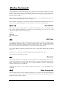
Run Other…
This command, on the Tools menu (also reached by Alt-O), lets you run other programs from
within the editor, then return to it when they finish.
When you select Run Other... you will first be warned if you have not saved your source code
(unless you have modified the setting of the Save files on Run Other option in Preferences).
Then the GEM file selector will appear, from which you should select the program you wish
to run. If it is a JOS or .TTP program you will be prompted for a command line, and then the
screen will be initialised suitably.
This is the command to use for 'one-off execution of a program within the editor. If you are
likely to want to run the same program a number of times, then use the facilities of the Tools
menu. If you would prefer to specify the program to run via a command line, rather than
using the file selector then use the Run with Shell command described below.
If you include the character sequence %. (i.e. per cent followed by full stop) in the command
line (remember, you are prompted for a command line) these characters will be replaced by
the full name of the file that you are currently editing. To pass the name without its extension,
use %?.
If you need a true % to be passed type %%.
Run with Shell...
This command also lets you run other programs from within the editor, then return to it
when they finish. The keyboard shortcut for this command is Shift-Alt-O.
It differs from Run Other in that you enter the file to run as a command line. If the editor finds
that the _shell_p vector has been set up then this will be called to execute the command. This
works well with the Craft, PKS and Gulam shells as the shell can be used to run batch files
and expand file wildcards etc.
If the _shell_p vector has not been set up then the editor will look for the file to run using
the PATH environment variable, which can be set using the Environment command from the
Options menu.
The same expansion of the current filename as used by Run Other can be used by this
command. If you wish to use the same command more than once you will probably save time
The Editor
Hisoft Devpac 3
Page 37
by using the Tools menu.
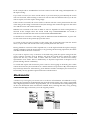
Setting the Path
The editor maintains a number of directory paths to make the operation of the integrated
environment natural and seamless.
Paths are routes to files. Normally you keep all files of a similar type or usage in one folder or
you may have a number of related folders all within one outer folder. For example if you
have a hard disk, you probably have a DEVPAC3 folder containing the HiSoft Devpac
program, its tools and its libraries.
In order that a program that uses these files can find them without having to ask the user for
help, both the operating system and the HiSoft Devpac editor maintain a number of directory
paths, some of which you can alter.
Here is a summary of the paths used by the integrated environment, how they are set and
what uses them:
Current directory - this is a path that is set up (initially) by the program which ran the current
program. For example, for the HiSoft Devpac editor this path will have been set up by the
Desktop, assuming of course you ran HiSoft Devpac from the Desktop. However, since the
editor allows this to be changed (via the Change Directory command on the File menu), it is
normally reset to whatever was last stored in the HISOFTED.INF file, to save you having to
change it every time you run the editor.
Most of the disk-related functions within the editor will search this path first.
GEMDOS path - this path is that contained in the PATH environment variable. It is used by
shells (e.g. Craft, PKS Shell, Gulam) to locate programs to run. It is specified as a list of , or ;
separated folder names, each of which specify a folder which should be searched when trying
to locate a file.
Within the editor it is used by Run with Shell, and to locate the named program. Other tools,
like WERCS, may use it for locating subsidiary files, such as WERCS.RSC and WERCS.INF.
AES path - this is the path used by the AES when the user calls one of the AES routines which
search for a file (shel_find and rsrc_load). Internally the format of this variable is identical to
the GEMDOS path (in fact it is the GEMDOS PATH for the AES program!), although the AES
provides no way of altering it and merely sets it to A:\ for a floppy based machine or C:\ for a
hard disk machine.
Environment...
The Environment... option allows the environment variables used by the tools which are run
to be altered. Only the variables which are needed are shown:
The Editor
Hisoft Devpac 3
Page 38
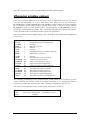
Miscellaneous Commands
Fonts...
The Fonts command is used to select different GEM or TOS fonts for use in the editor; it can
be selected either by clicking on Fonts... from the Options menu, or by pressing Control-G. It
displays a dialog box like this:
The GEM Font is the font that will be used by the editor to display text. In ST high resolution
and the TT resolutions, there are three fonts available as above. Changing to Small will double
the number of line displayed on the screen. With the Tiny font the characters are only 6 pixels
by 6 pixels wide but this does mean that even in ST high resolution, there are over 100
characters per line and 54 lines!
In ST medium resolution, there are only two fonts; Normal and Small. Small is 6 by 6 pixels
and thus the characters are difficult to read but this does give an extra 7 lines of text and over
100 characters per line.
TOS font is used by non-GEM programs. In ST high resolution, using 8x8 will give 50 lines
instead of 25.
You should be aware that any change of font that you make here will also be effective outside
the editor, after you leave it.
About Devpac-3...
It you select About Devpac-3... from the Desk menu, a dialog box will appear giving various
details about HiSoft Devpac, including its version number. You will also be told the amount
of free memory that is available to you and how much is used by the resident programs
including the text in the open windows.
The Editor
Hisoft Devpac 3
Page 39
Pressing Return or clicking on OK will return you to the editor.
ASCII Table...
To be found on the Edit menu, this displays a pop-up dialog box at the current mouse
position, showing all the ASCII characters:
You may click on an individual character and it will be added to the text that you are editing
at the current cursor position. You can bring up this display from the keyboard using ShiftInsert. This short cut can also be used in the editor's dialog boxes.
Note that the characters that would confuse the editor are 'greyed out' and may not be
selected. Remember that characters other than those in the standard 7 bit ASCII set are not
necessarily the same on other computers.
Help Screen
The key equivalents for the commands not found in menus can be seen by pressing the Help
key, or Alt- H. A dialog box will appear showing the cursor and function keys, as well as the
free memory left for the system.
Desk Accessories
If your system has any desk accessories, you will find them in the Desk menu. If they use their
own window, as Control Panel does, you will find that you can control which window is at
the front by clicking on the one you require.
For example, if you have selected the Control Panel it will appear in the middle of the screen,
on top of the editor window. You can then move it around and, if you wish it to lie 'behind'
the editor window, you can do it by clicking on an editor window, which brings the editor
window to the front; you can then re-size it so you can see some part of the control panel's
The Editor
Hisoft Devpac 3
Page 40
window behind it. When you want to bring the control panel back to the front just click on it
and the editor window will go behind. The editor's cursor only flashes and the menus only
work when an editor window is at the front.
Automatic Launching
You may configure HiSoft Devpac to be loaded automatically whenever a source file is
double-clicked from the Desktop, using the Install Application option.
To do this you first have to decide on the extension you are going to use for your files, which
we recommend to be .S for assembly language files. Having done this, go to the Desktop, and
click once on DEVPAC.PRG to highlight it. Next click on Install Application from the Options
menu and a dialog box will appear. You should set the Document Type to be S (or whatever
you require), and leave the GEM radio button selected. Finally click on the OK button (if you
press Return it will be taken as Cancel).
Having done this, you will return to the Desktop. To test the installation, double-click on a
file with the chosen extension which must be on the same disk and in the same folder as
HiSoft Devpac and the Desktop will load HiSoft Devpac, which will in turn load in the file of
your choice ready for editing or compilation.
Note: To make the configuration permanent, you have to use the Save Desktop option.
The Program Menu
The Program menu contains commands for assembling and running your
program. The commands on it are used to communicate with the other
parts of the package, the assembler, the debugger and, not least, the
program that you are developing.
Assemble
This command will assemble the file that is currently being edited using that have been set up
using the Assembler Options dialogs, which are described in detail at the beginning of the
next section.
If you are compiling to memory and get a program buffer full error when you assemble
something you should change the number given by Buffer size... on the Format popup menu.
There is of course a penalty for this - the bigger the program buffer size the smaller the
amount of memory left for the assembler itself to use while assembling your program. If the
assembler itself aborts with Out of memory it means there is not enough left for a complete
assembly - you should reduce the buffer size, or if this still fails you will have to assemble to
disk.
When you assemble to disk the program buffer size number is ignored, giving maximum
The Editor
Hisoft Devpac 3
Page 41
room in memory for the assembler itself. If you haven't saved your program source code yet
the file will be based on the name NONAME.
If there were any errors the editor will go to the first erroneous line and display the error
message in the status bar. Subsequent errors (and warnings) may be investigated by pressing
Alt-J.
If you have any include files loaded in other windows, these will be read directly from
memory; there is no need to save them to memory before saving them. If the first error occurs
in such an include file, then the editor will automatically switch to the appropriate window to
show the error.
Check
Check or Alt-Y is just like assemble except that it does not produce output to memory or disk.
If you know that your file contains errors this operation is slightly quicker than a normal
assembly, even than an assemble to memory.
Output Symbols
This is used to produce a .GS file from an include file. The pre-assembled symbol table that is
produced will then be loaded when you assemble a file that includes this file. Pre-assembly is
described in detail in the next chapter.
Running Programs
If you click on Run from the Program menu or press Alt-X you can then run a program
previously assembled into memory. When your program finishes it will return you to the
editor. If the assembly didn't complete normally for any reason then it is not possible to run
the program.
If your program crashes badly you may never return to the editor, so if in doubt save your
source code before using this, or the Debug command.
If only non-fatal errors occurred during assembly (e.g. undefined symbols) you
will still be permitted to run your program at your own risk.
Please Note
When issuing a Run command from the editor the machine may seem to 'hang up' and not
run the program. This occurs if the mouse is in the menu bar area of the screen and can be
corrected by moving the mouse. Similarly when a program has finished running, the machine
may not return to the editor. Again, moving the mouse will cure the problem. This is due to a
feature of GEM beyond our control.
Run with GEM
Normally when the commands Run, Debug or Mon are used the screen is initialised to the
normal GEM type, with a blank menu bar and patterned desktop. However if running a TOS
The Editor
Hisoft Devpac 3
Page 42
program this can be changed to a blank screen with flashing cursor, by clicking on Run with
GEM. A check-mark next to the menu item means GEM mode, no check mark means TOS
mode. The current setting of this option is remembered if you save the editor preferences.
Running a TOS program in GEM mode will look messy but work, but running a
GEM program in TOS mode can crash the machine.
Run Directory
Selecting Directory on the Program menu lets you choose the directory path that will be
passed to any programs that you run in memory. If you select Current then the editor's
current directory will be used; when Top Window is select the directory corresponding to the
top most window will be used.
This can be useful if your program needs to load subsidiary files as it can find them
immediately even if you have loaded the editor from another folder. Remember that you can
change the editor's current directory using the Change Directory command from the File
menu.
Debug
If you wish to debug a program previously assembled click on Debug from the Program
menu. This will invoke Mon to debug your program, included any debugging information
specified. The screen type selected is determined by the Run with GEM option, described
above.
Mon
This item will invoke Mon in a similar way to if it was invoked by double-clicking on the
program icon from the desktop, but instantly, as it is already in memory. You will return to
the editor on termination of the debugger. The screen type selected is determined by the Run
with GEM option, described above.
Debugger options
The integrated assembler makes available the debugger, Mon. The options for the debugger
(set via Control-P inside Mon) may also be set up within the integrated environment:
If you wish to use an alternative debugger (e.g. DB from Atari) this can be done by
The Editor
Hisoft Devpac 3
Page 43
naming a copy of the debugger MON.
The integrated assembler will notice such uses and not pass the debugger strange options!
Note that you should only make Mon resident (using the Resident... option), attempting to
make other debuggers resident will almost certainly crash the machine.
Auto '©'/'_' prefix labels
With this option set Mon will try prefixing symbols by _ and @ if it cannot find a label, so that
if you enter main and there is no label called main, then Mon will try _main or if this doesn't
exist then it will try @main.
Auto-load source
Using the default settings, Mon will automatically load a source file and run your program
until the label specified in the Start at label field, (i.e. the beginning of your main program),
ready for you to set a breakpoint in the code. Mon loads the source file corresponding to the
first module with debug information in the file that you are debugging.
Display 'ZAn' in disassembly
This option allows advanced programmers to enable the display of the normally hidden Z
registers used by some 680x0 instructions.
Note that the Display 'ZAn' in disassembly option will be disabled if running on an ST.
Enable timed screen switching
Defaulting to On, this causes the display to switch to that of your program only after 20
milliseconds. It should be switched off when a program is about to change a screen's address
or resolution and then turned back on afterwards.
Follow TRAPs
By default, single-stepping and the various forms of the Run command treat TRAPs, Line-A
and Line-F calls as single instructions. However by turning this option On the relevant
routines will be entered allowing ROM code to be investigated.
Ignore cartridge area
When this option is selected the Find command will not search the ROM cartridge area of the
memory map. You should select this is you have hardware other than a ROM in this slot.
Ignore label case
This option defaults to On. If it is set to On then if you enter fred in an expression the
subsequent search will give the value of the first symbol that matches this, ignoring case, thus
finding FRED, fred or Fred. This option is useful for lazy typists who use the same name with
different casing.
Interpret relative offsets
This option defaults to On and affects the disassembly of the address register indirect with
The Editor
Hisoft Devpac 3
Page 44
offset addressing modes, i.e. xxx(An). With the option on, the current value of the given
address register is added to the offset and then searched for in the symbol table. If found it is
disassembled as symbol (An). This option is required to show the addresses of your global
variables if they are accessed via an address register.
Symbol significance: sig
This option specifies the number of characters the debugger treats as significant for
identifiers. This can be useful if less than the default of 22 is required.
Source line numbers
Mon can either show line numbers in your source window in
decimal, hex or not at all.
Start at label: label
When an executable file is loaded normally Mon stops at the first location in the program. If a
different label is specified using this option (e.g. main for C, REF0001 for HiSoft BASIC),
then the program will instead be stopped at that point; this means you can start debugging at
the start of your code, rather than the going through the compiler's startup code.
Assembly Errors
When the assembler detects an error or something that may be an error (a warning) it
generates a message; these errors are remembered, and can be recalled from the editor; the
message is followed by the line and file in which the error was detected.
When you return to be editor you can use Alt-J to move to the next error with the error
message displayed in the status line. If you have a large number of errors the editor may not
be able to remember them all. Alt-J goes to the next error regardless of the position of the
cursor; it will switch windows is required. To go to a previous error use Control-J. The editor
takes account of any insertions or deletions automatically so that unless one error (like a
mistake in a definition) has caused multiple errors you should only need to compile once.
There's also the Shift-Alt-J command which finds the next error after the cursor in the current
window. It is the appropriate one to use if you have got a number of include files and want to
fix all the errors in one file before going on to the next one. You can also use it to find the first
error in a file by typing Alt-T (to go to the top) and then Shift-Alt-J.
Occasionally the assembler will spot errors somewhat later than you might expect. This is
usually because the text up to the point it has read is allowed in a certain context. If you have
missed something out at the end of a line, then the error may be detected at the beginning of
the next line.
On occasions the assembler will generate more than one error message as a result of a single
error in your program; do not be put off by this. If you get confused, just re-assemble.
The Editor
Hisoft Devpac 3
Page 45
Incidentally, if you start a assembly of a large program you can break out and returned to the
editor using the key combination Shift-Shift when using the integrated assembler.
See the Appendix B - Devpac error messages for details of all the error messages produced.
Resident Tools
This command, on the Options menu, lets you control how the Devpac programs are loaded
into memory.
There are two different ways that the editor can load a tool which it needs. Firstly, by default,
the tools (assembler and debugger) will be read into memory when the editor starts up. If,
however, you are low on memory, unchecking the boxes will only load the tool when
necessary.
A tool will be loaded by the editor when needed and then removed after use; you
do not have to have the tool permanently resident in order to use it.
To pre-load non-program files (such as include files or pre-assembled symbol files) we
recommend copying them into a RAM disk.
The Editor
Hisoft Devpac 3
Page 46
Chapter 3 - The Assembler
Introduction
Gen is a powerful, fast, full specification 680x0/6888x/68851 assembler, available instantly
from within the editor or as a standalone program. It converts the text typed or loaded into
the editor, optionally together with files read from disk, into a binary file suitable for
immediate execution or linking. It can also produce a memory image for immediate execution
from the editor.
Invoking the Assembler
From the Editor
Before using the assembler you will probably need to set up the assembler's options to reflect
your preferences. This is achieved via the first four entries on the Options menu.
The Control dialog
The control dialog
This dialog is used to control the assembly process.
Ignore multiple includes causes the assembler only to assemble an include file the first time
that it is included. This leads to slightly faster assembly times and is most useful when using
the operating system include files which may be called more than once. However you should
not use this option if the multiple includes are each intended to generate code.
Low memory assembly lets you reduce the memory requirements of the assembler by causing
it never to cache include files in memory. Under normal circumstances you should leave this
button unchecked, and select it only if the assembler runs out of memory.
The No warnings option suppresses the generation of assembler warnings.
The Assembler
Hisoft Devpac 3
Page 47
The Debug symbols popup lets you choose which symbols to include in
the executable.
You normally include symbols in a file so that you can see them when using the debugger.
The choices correspond to the following OPTs:
None
Normal
Exports
NODEBUG
DEBUG
XDEBUG
Note that the different options have different effects depending on the format of code being
generated; you should refer to the Output File Directives section.
Choosing Line debug includes information about the code addresses
corresponding to the line numbers in your program.
Two formats are available: Standard which uses LINE debug hunks that are compatible with
Lattice C. Compressed uses HCLN hunks which need approximately one quarter of the space
of LINE hunks but are not supported by Lattice C. Beware that even using the compressed
format increases the size of your program substantially. Mon understands both formats.
The Format popup lets you select the output format produced by the
assembler; Atari Executable, Linkable (GST, DRI or Lattice), S-records
or to RAM. The differences between these are detailed later.
Normally you will want to use Atari Executable or one of the RAM options. The final option
on this menu is Buffer size... which brings up the following dialog:
This sets the size of the buffer that is used when assembling to memory.
You will need to change this if you get a Program buffer full error message
from the assembler.
The 'EQU' symbols list box enables you to initialise the values of labels; each label has the
form: label=value, e.g.
FALCON030=1
would set the label FALC0N030 to have the value 1. Note that omitting value causes the label
to be set to the value 1.
The 'INCLUDE' directories list allows you to set up a list of directories that will be searched for
include files. Typically you will set this up to point to the main directory for your operating
system include files.
The Pre-assembled includes list allows you to set up any pre-assembled header files that will
be loaded before assembly begins. Such header files contain the symbol table information for
macros and absolute labels and are produced using the Output Symbols command from the
Program menu. These files are described in detail later.
Output is used to override the default name for the assembler's output file which is the same
as the main file but with a .PRG extension if executable, with a .O or .BIN extension if linkable
or a .MX extension if S-records are being produced. Even if you have specified an output
filename with this option you will still need to ensure that you have selected one of the disk
The Assembler
Hisoft Devpac 3
Page 48
based formats.
The Listing dialog
The Listing dialog
The List symbol table, List macro expansions, List conditionals only and First pass listing options
should be self explanatory. Generating a listing on pass one is only normally useful when
debugging complex usage of conditional assembly.
The Listing popup enables you to select an assembly listing. None will suppress
the listing, Screen and Printer will direct it to the appropriate device.
Disk will send the listing to a file based on the source filename but with the extension .LST. You
may set your own file or device for the listing file using the List to item.
Tab size sets the size of tabs in listing files.
The Options dialog
The Processor popup lets you select for which main processor the assembler
will generate code. If you are writing a program that is to run on all Atari TOS
computers leave this as 68000.
If you are writing a program specifically for the TT or Falcon030 then you should select
68030.
The 68881/2 maths coprocessor and 68851 memory management unit check boxes enable
the instructions for these coprocessors. Note that the 68851 should only be selected if you are
generated code for a 68020/68851 combination; the 68030 and 68040 processor options
automatically enable the MMU instructions for those particular chips. Equally it is not
necessary to select the maths co-processor when using the 68040.
Use Case insensitive labels to select whether labels are case dependent or not; if checked, then
Test and test would be treated as the same label, when not checked they are treated as
different.
The Assembler
Hisoft Devpac 3
Page 49
Symbol significance lets you define the number of characters that will be considered when
labels are compared. The default value is 127 characters, the maximum. The minimum value
is 8.
The Default branch size popup sets the default size for branch
instructions.
Using Word (the default) gives the same code as produced by 68000-only assemblers.
The remaining options correspond to the following OPT directives; these are described in
detail below.
Add automatic PC-relative
Allow narrow zero operands
Base displacement default word
Check absolutes for missing #
Check memory bitfield offsets
Ensure PC-relative code
No even indirection checking
No expression type checking
No supervisor instructions
Outer displacement default long
Underscore for local labels
AUTOPC
ALLOWZERO
BDW
CHKIMM
CHKBIT
CHKPC
NOEVEN
NOTYPE
USER
ODL
LOCALU
The Optimisations dialog
This dialog controls the optimisations that will be made automatically by the assembler. Most
of these can be set to one of Yes (Y), Warn (W) or Off (N); when W is selected the assembler
makes the optimisation and issues a warning so that you can see where it is modifying your
code. Switching an optimisation on (Y) causes it to be made without any warning.
The exact code transformations that these options perform are detailed below.
Running the assembler
Having selected your required options you should select the Assemble menu item from the
Program menu or press Alt-A to start the assembly. At the end of assembly if any errors
occurred the cursor will be positioned on the first offending line.
If you wish to check the syntax of a program rather than actually assembling it to memory or
disk, you can use the Check item from the Program menu - this is exactly like a normal
The Assembler
Hisoft Devpac 3
Page 50
assembly but it does not output any code; the keyboard shortcut for this is Alt-Y.
The final form of assembly is to produce a pre-assembled header file so that you can use it via
the Pre-assembled includes item on the Assembler options - Control dialog. To produce a preassembled file select Output Symbols. Note that files that are used in this context may not
contain code - only definitions of macros and constants.
Assembly to Memory
To reduce development time Gen can assemble programs to memory, reducing disk access
time. Such programs may self-modify if required as a re-executed program will be in its
original state.
You should be careful when running from memory under the 68020 processor and above;
these chips have an instruction cache and, if you modify an address that is already in the
instruction cache, your new code will not be executed!
Stand-Alone Assembler
You can invoke the assembler from within the editor or from the Shell or CLI using the
standalone assembler.
The standalone version of the assembler is called GEN.TTP and, if it is called without a
command line, you will be prompted for one conforming to the rules below; enter the options
you want and press Return or press Return immediately to abort.
At the end of an assembly invoked from the editor, Gen will automatically return to the
editor. If a command line has been supplied manually the assembler will not wait for a key at
the end of the assembly as it assumes it has been run from a CLI or batch file.
Command Line Format
The Gen command line consists of a series of options and the name of the main file that you
wish to assemble. There may be options before and/or after the filename. You can use any of
the long forms of OPT option names directly by preceding them with the + character. These
are described in detail later.
The additional options that can be used from the command line are as follows; the
corresponding OPT directive is shown in parentheses, where relevant. The latter options may
be used on the command line with a leading +.
-B
no binary file will be created.
-C
case insensitive labels (+NOCASE).
-D
debug (+DEBUG).
-E
allows labels to be set; assignments must be separated by commas; see below for
further details.
-H
specify the pre-assembled header files that are to be loaded before assembly starts.
Multiple files may be separated with a comma.
-I
specify include directories to be searched (follow immediately with path). These
directories will be searched when the assembler is opening include files; they should
The Assembler
Hisoft Devpac 3
Page 51
normally be terminated with a slash.
-L
GST linkable code (+GST).
-L2
DRI linkable code (+DRI).
-L6
output Motorola S-records (+SREC).
-L7
Lattice linkable code (+LATTICE).
-M
use low memory (slower) assembly mode. See the section on integrated options in the
previous chapter. Not the same as OPT M+.
-O
specify output filename (which should follow immediately after O).
-P
specify listing filename (which should follow immediately after P), defaults to source
filename with extension of .LST. This may be any device.
-Q
pause for key press after assembly.
-S
include a symbol table at the end of the listing.
-T
specifies the tab setting for listing. For example -T10 uses a tab setting of 10.
-V
specify options as if they were specified using OPT on the second line of the main
source file; note it is normally easier to us the +option format.
-X
use extended format symbols in executable (+XDEBUG).
-W
specify a file that contains a list of options to be used (which should follow
immediately after W). There may only be one -W file per assembly and this option may only be
used on the command line.
-Z
enable listing on pass 1. The information in the code field may be incorrect but this
can be used to find mistakes when omitting an ENDC (+LIST1). This is provided for backward
compatibility; +TRACEIF can normally be used to find such errors more quickly.
The default is to create a executable binary file with a name based on the source file and
output file type, no listing, with case sensitive labels.
Some examples of command lines:
gen test -b
assembles test..S with no binary output file.
gen test -oc:\test.prg -p
assembles test.s into a binary file c:\test.prg and sends a listing file to test. 1st.
gen test
-l1dpprn:
assembles test.s into GST linkable code with debug and a listing to the parallel port; a listing
to the serial port can be obtained by specifying aux: as the listing name.
gen test +GST +DEBUG -pprn:
The Assembler
Hisoft Devpac 3
Page 52
achieves the same effect.
gen test -wtest.opt
assembles the file test.s using the options contained in the file test.opt.
Defining Labels on the Command-Line
The -E option allows symbols to be defined at assembly time without having to change the
source file. This option can be followed by one or more assignments of the form
symbol=expression
where symbol and expression follow the normal rules of the assembler and may contain
values that have been defined previously. Multiple assignments must be separated by
commas. If you omit the =expression, then the symbol will be assigned the absolute value
1.
Assembly Process
Gen is a two-pass assembler; during the first pass it scans all the text in memory and from
disk if required, building up a symbol table. If syntax errors are found on the first pass these
will be reported and assembly will stop at the end of the first pass, otherwise, during the
second pass the instructions are converted into bytes, a listing may be produced if required
and a binary file can be created on the disk. During the second pass any further errors and
warnings will be shown, together with a full listing and symbol table if required.
If started from the command line assembly may be aborted by pressing Control-C, although
doing so will make any binary file being created invalid as it will be incomplete and should
not be executed.
Assemblies started from the editor may be aborted by holding down both Shift keys.
Return Codes
If using the comand line version of the assembler from batch- or make-files, you may exploit
the codes the program returns. These are:
100+
20
10
5
0
initialisation failure
fatal error
error(s)
warning(s)
OK
Binary file types
There are five main types of binary files which may be produced by Devpac, for different
types of applications. They are Atari executable, DRI linkable, GST linkable, Lattice linkable
and Motorola S-records.
The Assembler
Hisoft Devpac 3
Page 53
Devpac can also assemble executable code directly to memory when using the integrated
version allowing very fast edit-assemble-debug-run times.
When producing linkable code, Devpac does not produce an executable file, but a file that
needs to be processed by a linker to produce an executable file. An advantage of using this
format is that your program can be linked with the output of a high level language compiler
such as HiSoft BASIC. You can also use linkable code to split your assembly program into a
number of modules.
Motorola S-records are the industry standard method of programming EPROMs and for
standalone systems that use the 680x0 family of processors. The code produced is an ASCII
file that runs at a particular address. As a result S-records are not suitable for executing
directly under TOS but are ready for downloading to an EPROM programmer or stand-alone
system.
The type of executable file may be specified using the assembly options box, by using - L on
the command like or OPT and then the format name within the source code. Such a directive
must be placed before any code is generated and to avoid any confusion should be before any
module or section directives.
The different possibilities are summarised in the table below:
Lx
0
1
2
6
7
OPT name
ATARI
GST
DRI
SREC
LATTICE
Result
Atari executable
GST linkable
DRI linkable
Motorola S-records
Lattice C linkable code
Extension
.PRG
.BIN
.o
.MX
O
Thus you can select Lattice C linkable code from the assembler options box or by using a
command line like:
test
-17
or by including
opt
LATTICE
at the start of the file.
For the curious, L values of 3,4 and 5 are used by other products in the Devpac family ensuring source code compatibility across the range.
Output Filename
Gen has certain rules regarding the calculation of the output filename, using a combination of
that specified at assembly time (either in the Output to: field in the assembler control options
box or using the - 0 option on the command line) and the OUTPUT directive:
If an output filename is explicitly given at assembly time then
name=explicit filename
The Assembler
Hisoft Devpac 3
Page 54
else if the OUTPUT directive has not been used then
name=source filename + .PRG, .BIN, .O or .MX
else if the OUTPUT directive specifies an extension then
name=source filename + extension in OUTPUT
else
name=name in OUTPUT
Types of code
Unlike most 8-bit operating systems, but like most 16-bit systems, an executable program
under TOS will not be loaded at a particular address but, instead, be loaded at an address
depending on the exact free memory configuration at that time.
To get around the problem of absolute addressing the TOS file format includes relocation
information allowing TOS to relocate the program after it has loaded it but before running it.
For example, the following program segment
move.l
#string,a0
.
.
.
string
dc.b
'Press any key',0
places the absolute address of string into a register, even though at assembly time the real
address of string cannot possibly be known. Generally the programmer may treat
addresses as absolute even though the real addresses will not be known to him, while the
assembler (or linker) will look after the necessary relocation information.
For certain programs, normally games or for S-record production an absolute start
address may be required, for this reason the ORG directive is supported.
The syntax of the language accepted by the assembler will now be described.
Assembler Statement Format
Each line that is to be processed by the assembler should have the following format:
Label
Mnemonic
Operand(s)
Comment
start
move.l
dO,(aO)+
store the result
Exceptions to this are comment lines, which are lines starting with an asterisk or semicolon,
The Assembler
Hisoft Devpac 3
Page 55
and blank lines, which are ignored. Each field has to be separated from the others by white
space - any number or mixture of space and tab characters.
Label field
The label should normally start at column 1, but if a label is required to start at another
position then it should be followed immediately by a colon (:). Labels are allowed on all
instructions, but are prohibited on some assembler directives, and absolutely required on
others. A label may start with the characters A-Z, a-z, @ or underline (_), and may continue
with a similar set together with the addition of the digits 0-9 and the period (.). Note that the
@ character is allowed as the first character except when followed by a digit from 0-7 when it
is taken as the start of an octal number.
Labels starting with a period are local labels, described later. Sequences of digits terminated by
a $ are also local labels. Macro names and register equate symbols may not have periods in
them, though macro names may start with a period. By default the first 127 characters of
labels are significant, though this can be reduced if required. Labels should not be the same as
register names, or the reserved words SR,CCR,USP or any of the other special registers
described under Special Addressing Modes below.
By default labels are case-sensitive though this may be changed.
Some example legal labels are:
test, TEST, _test, _test.end, tests, _5test, @test
Some example illegal labels are:
5test,_&e, test>,
There
are
three
reserved
symbols
in
Devpac,
underline characters. These are __LK, __RS and __G2.
all
starting
with
two
Mnemonic Field
The mnemonic (or opcode) field comes after the label field and can consist of 680x0 assembler
instructions, assembler directives or macro calls. Some instructions and directives allow a size
specifier) separated from the mnemonic by a period. Allowed sizes are .B for byte, .W for
word, .L for long and .S for short. In addition floating point instructions may also have sizes of
.X for extended, .D for double, .P for packed decimal and .S for short floating point. Some of
the MMU instructions have a size of .D indicating a double long word (64-bits).
The specifiers which are allowed depend on the particular instruction or directive. Gen is
case-insensitive to mnemonic and directive names, so Move is the same as move and the same
as mOvE, for example.
Operand Field
For those instructions or directives which require operands, this field contains one or more
parameters, separated by commas. Devpac is case-insensitive regarding register names so
they may be in either, or mixed, case.
The Assembler
Hisoft Devpac 3
Page 56
Comment Field
Any white space not within quotation marks found after the expected operand(s) is treated as
a delimiter for a start of the comment and will be ignored by the assembler.
Examples of valid lines
move.l
loop
d0,(a0)+
comment is here
TST.W dO
lonely.label
rts
* this is a complete line of comment
;
and so is this
indented: link a6,#-10 make room
a_string:
dc.b
'spaces allowed in quotes'
a string
Expressions
Gen allows complex expressions and supports full operator precedence, parenthesis and
logical operators.
Expressions are of two main types - absolute and relative - and the distinction is important.
Absolute expressions are constant values which are known at assembly-time.
Relative expressions are program addresses which are not known at assembly-time as the
TOS loader can put the program where it likes in memory. Some instructions and directives
place restrictions on which types are allowed and some operators cannot be used with certain
type-combinations.
Symbols used in expressions will be either relative or absolute, depending on how they were
defined. Labels within the source will be relative, while those defined using the EQU directive
will be the same type as the expression to which they are equated.
The use of an asterisk (*) denotes the value of the program counter at the start of the
instruction or directive and is always a relative quantity.
Operators
The operators available, in decreasing order of precedence, are:
unary minus (-) and plus (+)
bitwise not (~)
shift left (<<) and shift right (>>)
The Assembler
Hisoft Devpac 3
Page 57
bitwise And (&), Or (!) and Xor (^)
multiply (*) and divide (/)
addition (+) and subtraction (-)
equality (=), less than (<), greater than (>), inequality (<>), less than or equals (<=), greater
than or equals (>=)
The comparison operators are signed and return 0 if false or -1 ($FFFFFFFF) if true. The shift
operators take the left hand operand and shift it the number of bits specified in the right hand
operand; vacated bits are filled with zeroes.
This precedence can be over-ridden by the use of parentheses ( and ). With operators of equal
precedence, expressions are evaluated from left-to-right. Spaces in expressions (other than
those within quotes as ASCII constants) are not allowed as they are taken as the separator to
the comment.
All expression evaluation is done using 32-bit signed-integer arithmetic, with no checking of
overflow.
Note that | (vertical bar) may be used as a synonym for ! (or) and that ! = may be used as a
synonym for <> (inequality).
Numbers
Absolute numbers may be in various forms:
decimal constants, e.g. 1029
hexadecimal constants, e.g. $12f
octal constants, e.g. @730
binary constants, e.g. %1100010
character constants, e.g. 'X'
$ is used to denote hexadecimal numbers, % for binary numbers, § for octal numbers and
single ' or double quotes " for character constants.
The default base for numbers may be changed using the RADIX directive.
Character Constants
Whichever quote is used to mark the start of a string must also be used to denote its end and
quotes themselves may be used in strings delimited with the same quote character by having
it occur twice. Character constants can be up to 4 characters in length and evaluate to rightjustified longs with null-padding if required. For example, here are some character constants
and their ASCII and hex values:
"Q"
'hi'
"Test"
"it's"
'it''s'
The Assembler
Q
hi
test
it's
it's
$00000051
$00006869
$54657374
$69742770
$69742770
Hisoft Devpac 3
Page 58
Strings used in DC.B
with the directive later.
statements
follow
slightly
different justification rules, detailed
Floating point constants
Floating point constants are only allowed as arguments for floating point instructions and
FEQU directives. Such constants may either be expressed in hexadecimal or conventional
decimal notation. Hexadecimal floating point constants should be preceded by : or $; the
colon is the Motorola standard. When using hexadecimal the way in which the value is
interpreted depends on the size used in the instruction. Thus
fmove.x
#$400000008000000000000000,fpO
fmove.s
#$40000000,fpO
fmove.d
#:4000000000000000,fpO
fmove.p
#$000000020000000000000000,fp0
fmove.s
#2.0,fpO
all load the floating point, register FPO with the value 2.0.
For a description of the floating point formats see Appendix E.
Decimal numbers consist of one or more decimal digits followed by an optional fractional
part consisting of a full stop (period) and an arbitrary number of decimal digits, optionally
followed by an exponent consisting of the letter E or e and a signed decimal exponent. The
maximum values allowed depend on the size of the appropriate instruction.
fmove.s
#2,fp0
fmove.x
#2E1,fpO
fmove.x
#12345.678e-789,fp1
fmove.x
#0.001,fp2
fmove.x
#-1.2345E1234,fp3
The only operator that is allowed in floating point expression is the unary minus (-) operator.
Allowed Type Combinations
The table below summarises for each operator the results of the various type combinations of
parameter and which combinations are not allowed. An R denotes a Relative result, an A
denotes absolute and a * denotes that the combination is not allowed and will produce an
error message if attempted.
Shift
operators
Bitwise
operators
The Assembler
A op A
A
A
A op R
*
*
*
*
R op A
*
*
*
*
Hisoft Devpac 3
R op R
*
*
*
*
Page 59
Multiply
Divide
Add
Subtract
Comparisons
A
A
A
A
A
*
*
R
*
*
*
*
R
R
*
*
*
*
A
A
Addressing Modes
The available 68000 addressing modes are shown in the table below. Please note that Gen is
case-insensitive when scanning addressing modes, so dO and A3 are both valid registers.
Form
dn
An
(An)
(An)+
-(An)
d(An)
d(An,Rn.s)
d.W
d.L
Meaning
data register direct
address register direct
address register indirect
address register indirect
with post-increment
address register indirect
with pre-decrement
address register indirect
with displacement
address register indirect
with index
absolute short address
absolute long address
Example
d3
a5
(a1)
(a5)+
-(aO)
20(a7)
4(a6,d4.L)
$0410.W
$12000.L
d(PC)
program counter
with offset
relative NEXT(PC)
d(PC,Rn.s)
program counter
with index
immediate data
relative NEXT(PC,a2.W)
denotes register
from 0 to 7
denotes a number
number
R
denotes
index
either aord
register,
s
denotes size, either W or U
when omitted defaults to W
#d
n
d
#26
When using address register indirect with index the displacement may be omitted, for
example
move.l
(a3,d2.1),d0
will assemble to the same as
move.l
0(a3,d2.1),d0
The modes discussed above can be used regardless of the processor type. The following are
additional modes that are only available when using a 68020 or later processor.
The Assembler
Hisoft Devpac 3
Page 60
Extended Index Registers for 68020
Certain existing modes have been extended to support a scale on the index register as follows:
exp(An,Xn<.size><*scale>)
exp(PC,Xn<.size><*scale>)
If the above syntax is used then the expression must fit into 8 bits; if it is larger then the new
modes (bd, an , Xn) / (bd, PC, Xn) should be used. Suppressed (Z) registers cannot be used
with this syntax. See below.
New 68020 Modes
The new modes in their most basic form are:
(bd.An.Xn)
([bd,An],Xn,od)
([bd.An.Xn] ,od)
(bd.PC.Xn) ,od)
([bd,PC],Xn,od)
([bd,PC,Xn],od)
address register indirect with index (base displacement)
memory indirect post-indexed
memory indirect pre-indexed
program counter indirect with index (base displacement)
program counter indirect post-indexed
program counter indirect pre-indexed
Every item in the above is optional and within each set of brackets the item list may be in any
order. In general the meaning of the syntax is that the processor takes the sum of any items in
brackets and then performs an indirection (memory access) for each set of brackets.
For example, consider,
move.w
([$12.w,a1,d1],$24.w),d0
and let us assume that a1 has the value $1230002 and d1 has the value $1234. Then this will
cause the processor to calculate a1+d1+$12 (giving $1231248) and fetch the long word value
from that address. Assuming $1231248 contains $12345678 then $24 will be added to this
(giving $1234569C) and finally the word contents of $1234569C will be loaded into the least
significant word of d0.
Depending on which items have been omitted, the assembler may change the choice of
addressing mode to be more optimal. If you wish to have a particular mode with missing
items then the item may be suppressed using Z-notation, i.e. specifying ZAn, or ZPC, as
required. The elements described above are further detailed below:
bd - Base Displacement
This is an expression which may be relative or absolute, word or longword in size. The
default size is long, but word may be forced by adding .W after the expression. The default
size itself may be changed with the BDW and BDL options. If the base displacement is known
on pass 1 the size can be optimised automatically by Gen using opt 08+.
Xn - Index Register, with optional size and scale
This item has the general form Xn<.size><*scale> where the size may be .W (the default)
or .L. The scale must evaluate to 1, 2, 4 or 8.
The Assembler
Hisoft Devpac 3
Page 61
od - Outer Displacement
This is an expression which may be word or longword in size but must be absolute. The
default size is word, but long may be forced by adding .L after the expression. The default size
itself may be changed with the ODW and ODL options. If the outer displacement is known on
pass 1 the size can be optimised automatically by Gen using opt 09+.
New 68020 Syntax for Old Modes
The new syntax for the old modes is:
(d16,An)
(d8,An,Xn)
(d16,PC)
equivalent to exp (An)
equivalent to exp(An,Xn), though Xn may be scaled
equivalent to exp(PC)
(d8,PC,Xn)
equivalent to exp(PC,Xn), though Xn may be scaled
If any items are explicitly suppressed then a suitable new 68020 addressing mode will be
used.
Ordering Rules
Any set of items within brackets may be ordered arbitrarily, though care should be taken if
two address registers are specified; the leftmost register will be used as the base register, the
rightmost as the index register. For example the mode:
(a3,isize,a2)
is specified the assembler will assume a3 is the base register and a2 will be sign-extended
from 16-bits, as .W is the default index size.
Data Register Indirect
The 68020 allows data register indirection, by suppressing suitable items, but take care; the
default size for index registers is word, so the line
move.l
(d3),d0
will actually be coded as
move.l
(0,za0,d3.w),d0
the (bd,An,Xn) form
which will indirect via the sign-extended value of d3; the likely correct line is
move.l
(d3.l),d0
Special Addressing Modes
CCR
SR
The Assembler
condition code register
status register
Hisoft Devpac 3
Page 62
USP
user stack pointer
In addition to the above, SP can be used in place of A7 in any addressing mode, e.g.
4(SP,d3.W)
The data and address registers can also be denoted by use of the reserved symbols R0
through R15. R0 to R7 are equivalent to d0 to d7; R8 to R15 are equivalent to AO to A7. In
general we recommend sticking to the standard register names, but this option can be useful
when porting code from other assemblers or to simplify tools which generate assembly
language.
The registers above are available on all 68000 family processors. The following registers are
only available on higher processors and in the 68851 MMU. The use of some of these registers
varies from chip to chip.
AC
BACO-7
BADO-7
CAAR
CACR
CAL
CRP
access control register
breakpoint acknowledge control register
breakpoint acknowledge data register
cache address register
cache control register
current access level
CPU root pointer
DRP
DTTO,
ISP
ITTO,
MMUSR
MSP
PCSR
PSR
SCC
SFC, DFC
SRP
TC
TTO, TT1
URP
VAL
VBR
DMA root pointer register
data transparent translation registers
interrupt stack pointer
instruction transparent translation registers
MMU status register
master stack pointer
MMU cache status register
MMU status register
stack change control register
alternate function code registers
supervisor root pointer
MMU translation control register
translation control registers
user root pointer
validate access level register
vector base register
In general, user programs running under TOS should not use these registers since they are
reserved for use by the operating system; some low level programs may find it necessary to
manipulate the cache control register if using self-modifying code.
Floating point registers
FP0-FP7
FPCR
The Assembler
general purpose floating point registers
floating point control register
Hisoft Devpac 3
Page 63
FPSR
FPIAR
floating point status register
floating point instruction address register
The addressing modes used in conjunction with the floating point instructions are the same as
those for the 'ordinary' instructions, although you should note that the floating point
instructions always use at least one floating point register.
Local Labels
Gen supports local labels, that is labels which are local to a particular area of the source code.
These are denoted by starting with a period and are attached to the last non-local label, for
example:
len1
move.l
4(sp),a0
.loop tst.b (a0)+
bne.s .loop
rts
len2
move.l
4(sp),a0
.loop tst.b -(aO)
bne.s .loop
rts
There are two labels called .loop in this code segment but the first is attached to lenl, the
second to len2.
As the local labels are attached in this way, you must have at least one real label before the
first local one.
If you wish to use global labels starting with a dot you may use OPT LOCALU to allow this an
make the underline character introduce local labels.
The local labels .W and .L are not allowed to avoid confusion with the absolute addressing
syntax.
You may also use strings of decimal digits terminated by a $ sign as local labels. This facility
has been provided for compatibility with other assemblers; we recommend the use of form
shown above as this makes programs much more readable.
Symbols and Periods
Symbols which include the period character can cause problems with Gen due to absolute
short addressing.
The Motorola standard way of denoting absolute short addresses causes problems as periods
are considered to be part of a label, best illustrated by an example:
move.l
The Assembler
vector.w,dO
Hisoft Devpac 3
Page 64
where vector is an absolute value, such as a system variable. This would generate an
undefined label error, as the label would be scanned as vector .w.
To work around this, the expression, in this case a symbol, may be enclosed in brackets, e.g.
move.l
though
the
(vector).w,dO
period
move.l
may
still
be
used
after
numeric
expressions,
e.g.
402.w,d0
Devpac 1 supported the use of \ instead of a period to denote short word
addressing and this is still supported in this version, but is not recommended
due to the potential for \W and \L to be mistaken for macro parameters.
Instruction Set
Word Alignment
All instructions with the exception of DC.B and DS.B are always assembled on a word
boundary. Should you require a DC.B explicitly on a word boundary, use the EVEN directive
before it. Although all instructions that require it are word-aligned, labels with nothing
following them are not word-aligned and can have odd values. This is best illustrated by an
example:
nop
will always be word aligned
dc.b
'odd'
start
tst.l (a0)+
bne.s start
The above code would not produce the required result as start would have an odd value. To
help in finding such instructions the assembler will produce an error if it finds an odd
destination in a BSR or BRA operand. Note that such checks are not made on any other
instructions, so it is recommended that you precede such labels with an EVEN directive if you
require them to be word-aligned. A common error is deliberately not to do this, as you know
that the preceding string is an even number of bytes long. All will be well until the day you
change the string...
Instruction Set Extensions
The complete 68000-68040 instruction set is supported (depending on the processor selected)
together with the 68881/68882 and 68551 coprocessors. A number of standard shorthands are
automatically accepted as detailed below. A complete description of the 68000 instruction set
can be found in the supplied pocket guide. Full details of the instructions for the other chips
including syntax and addressing modes can be found in the M68000 Family Programmer's
The Assembler
Hisoft Devpac 3
Page 65
Reference Manual which is available from HiSoft.
Condition Codes
The alternate condition codes HS and LO are supported in Bcc, DBcc and Scc instructions,
equivalent to CC and CS, respectively.
Branch instructions
To force a short branch use Bcc.B or Bcc.S, to force a word branch use Bcc .W or to leave
to the optimiser use Bcc. To use a 32 bit branch when 68020 or above code generation is in
effect then use Bcc.L.
When 68000/68008/68010 code generation is selected Bcc.L is interpreted as a Bcc.W with a
warning for compatibility with Devpac 1. To cause Bcc.L to be converted to Bcc.W
regardless of the processor selected then use OPT OLD as described elsewhere.
A BRA.S to the immediately following instruction is not allowed but may be converted, with
a warning, to a NOP using OPT 07+ (see the options sub-section for details). A BSR.S to the
immediately following instruction is not allowed and will produce an error.
DBRA Instruction
DBRA is accepted as an equivalent to DBF.
ILLEGAL Instruction
This generates the op-code word $4AFC.
LINK Instruction
If the displacement is positive or not even a warning will be given.
MOVE from CCR Instruction
This is a 68010 and upwards instruction, converted with a warning to MOVE from SR when
68000 only code is selected.
MOVEQ Instruction
It the data is in the range 128-255 inclusive a warning will be given. It may be disabled by
specifying a long size on the instruction.
Assembler Directives
Certain pseudo-mnemonics are recognised by Gen. These assembler directives, as they are
called, are not (normally) translated into opcodes, but instead direct the assembler to take
certain actions at assembly time. These actions have the effect of changing the object code
produced or the format of the listing. Directives are scanned exactly like executable
instructions and some may be preceded by a label (for some it is obligatory) and may be
followed by a comment. If you put a label on a directive for which it not relevant, the result is
undefined but will usually result in the label being ignored.
Each directive will now be described in turn. Please note that the case of a directive name is
not important, though they generally are shown in upper case. The use of brackets ([ ]) in
The Assembler
Hisoft Devpac 3
Page 66
descriptions denote optional items, ellipses (...) denote repeated items.
Assembly Control
END
This directive signals that no more text is to be examined on the current pass of the assembler.
It is not required.
INCLUDE
filename
This directive will cause source code to be taken from a file on disk and assembled exactly as
though it were present in the text. The directive must be followed by a filename in normal
TOS format.
A drive specifier, directory and extension may be included as required, e.g.
include
c:\devpac\includes\header.i
Include directives may be nested as deeply as memory allows and if any error occurs when
trying to open the file or read it, assembly will be aborted with a fatal error. When using the
integrated editor if an include file is loaded then this will be read direct from memory; there
is no need to save it to disk before assembly.
If you have checked the Ignore multiple includes item in the Assembler Options - Control
dialog or used the OPT INCONCE option, then attempts to include a file a second time will be
ignored.
If no drive is specified, that of the main source file will be used when trying to open the file.
For maximum flexibility, Gen allows a two ways of specifying where include files may be
found without the need to specify the full pathname as in the example above.
First, the Assembler Options - Control dialog 'INCLUDE' directories list (and its command line
equivalent the -I option) lets you set directories that will be searched to find the include files.
Second you can use the INCDIR directive itself to add to this path list.
Thus typically you use the assembler dialog to set up the directory for the system includes
and use the INCDIR directive for any files that are specific to this particular program.
The more memory the better, Gen will read the whole of the file in one go if it
can and not bother to re-read the file during pass 2.
Pre-assembled files
When searching for include files Gen also looks for a file with the same name as the include
file but with any extension replaced with .GS. This is assumed to be a pre-assembled symbol
table file corresponding to that file name.
Such a file is produced using the Output Symbols option from the Program menu or by using
The Assembler
Hisoft Devpac 3
Page 67
the OPT GENSYM option. The .GS file that this produces contains the symbol table definitions
for the absolute labels and macros that are defined by the include file. It also lists the files that
the include file has included itself.
When the assembler loads a .GS file the labels and macros contained within it are added to
the symbol table for the new assembly. If a definition is already present then it is ignored.
Any subsequent references to this include file and the files that it includes will be ignored.
Thus if you Output Symbols from the Devpac include file GEMMACRO.I this will generate
GEMMACRO.GS. Your programs that use this include file will then load the .GS file and will
assemble more quickly. You can even delete the original include file if you wish (make sure
you have a copy of the source first, though!).
If you know that your program is going to include a particular pre-assembled file you can
load it before assembly starts using the Pre-assembled includes dialog from the Assembler
Control dialog or via the command line -H option.
Note that you cannot pre-assemble files that generate code, i.e. files such as
AESLIB.S may not be pre-assembled.
INCDIR
pathnamelisf
The INCDIR directive lets you specify directories that will be searched for include files as well
as those specified via the -I command line flag or Include list in the assembler control dialog.
The format for pathnamelist is a list of items separated by commas or semicolons and the
directories should be terminated by a backslash. Pathnames that contain spaces should be
enclosed in quotes.
INCBIN
filename
This takes a binary file and includes it, verbatim, into the output file. Suggested uses include
screen data, sprite data and ASCII files. The INCBIN directive uses the same method for
finding files as the INCLUDE directive above.
The included data is forced to an even boundary, however the section counter is not forced to
an even boundary after the include if the file is an odd number of bytes in length.
OPT
option[,option ...]
There are a very wide range of options controlling all aspects of the assembly process; some
may be set with their own option letter on the command-line, all may be set with an OPT
directive within the source file, and most may also be set on the command-line using either a
leading +, or the - v option.
Devpac 2 and below only supported options denoted with an alphabetic character followed
by + or -; however owing to the large number of options, these have been supplemented with
keywords. The old format options are still accepted.
Note that options specified on the command line override options specified on line 1 of the
source; this does not apply to the integrated environment.
The options are as follows:
The Assembler
Hisoft Devpac 3
Page 68
Processor selection
P=type
allows selection of processor type; type may be one of 68000, 68008, 68010,
68020, 68030, 68040 or 68332. Optional co-processors may be specified, separated by a /
and may be any combination of 68881, 68882 or 68851. Specifying a main processor will
de-select any current co-processor.
68020 Default Displacement Sizes
BDW
makes any unsized base displacements used in 68020 addressing modes word-sized;
this will cause errors if you have any relocatable references as they cannot fit into a word.
BDL
makes any unsized base displacements long-sized.
ODW
makes any unsized outer displacements word-sized.
ODL
makes any unsized outer displacements long-sized.
All of the above can be overridden on an individual basis by specifying .W or .L after the
expression. In general we recommend the use of such explicit specifiers as it makes code more
portable.
See below for automatic optimisation of long displacements into short ones.
Branch Control
OLD
ordinarily a BRA.L is converted into a BRA.W with a warning, unless you selected a
68020 or higher processor in which case it will generate a BRA.L, a 32-bit PC-relative branch.
The use of this option will force BRA.Ls to always be converted to BRA.Ws, regardless of the
processor type selected. Note that this option is not available in the integrated environment.
BRW
unsized branch instructions will default to BRA.W, unless optimisation type 1 is
selected when it may be promoted to BRA.S.
BRB
unsized branch instructions will default to BRA.S; errors will be generated if the
branch is out of range.
BRS
as above; included for Motorola compatibility.
BRL
unsized branch instructions will default to BRA.L; P=68020 or P=68030 mode must
be selected for this option to be valid.
The default option is BRW.
Symbol Case Sensitivity
By default all symbols are case-sensitive, though this can be overridden on the command-line.
The default length of symbol significance is 127 characters, the maximum.
CASE
symbols are case sensitive.
NOCASE
Cx
symbols are case-insensitive.
treat x characters as significant (x=8 -127).
The Assembler
Hisoft Devpac 3
Page 69
Cx+
symbols are case-sensitive to x characters.
Cx-
symbols are case-insensitive to X characters.
Although it is unlikely to be useful, it is possible to use these options at any time in a source
file and an unlimited number of times.
Listing Control
By default an assembly listing will show macro calls in the same form as those in the source.
MEX
expand macro calls in the listing.
NOMEX don't expand macro calls.
By default there will be no symbol table listing, unless -S is specified on the command-line,
or the option below is used:
SYMTAB
select a symbol table listing.
NOSYMTAB
disable a symbol table listing.
LIST1 enable assembly listing on pass one.
N0LIST1
disable listing on pass one (default).
Pass one listing is not useful generally, because the data for the instructions may be wrong. It
can be useful when tracking down mistakes with conditional assembly and macros.
TRACEIF
enable tracing of conditional assembly on pass one.
NOTRACEIF
disable this tracing (default).
The TRACEIF option is designed for finding mistakes in complex use of conditional assembly
and as such is only for experienced assembly language users. Conditional assembly is
described in a later section in this chapter. TRACEIF gives a list of only the IFxx,
ELSE/ELSEIF and ENDC directives together with a display of the conditional assembly
counter.
Output File Format
ATARI,GST,DRI,SREC,LATTICE
These select the output file format and must be before the first line of the source file that
generates code; for further details please see the beginning of this chapter.
GENSYM
This causes Gen to output a symbol table (or pre-assembled) file with
extension .gs rather than a conventional output file. As such this command can only be used
for include files that do not generate any code. See the section above on Pre-assembled files.
Optimisation
Gen is capable of optimising certain statements to faster and smaller versions. By default all
optimising is off but each type can be enabled and disabled as required. This option has
several forms:
The Assembler
Hisoft Devpac 3
Page 70
O1+
will optimise backward branches to short if within range, can be disabled with O1-.
O2+
will optimise address register indirect with displacement addressing modes to
address register indirect, if the displacement evaluates to zero. It can be disabled with 02-.
For example:
move.l
next(a0),d3
will be optimised to:
move.l
(a0),d3
if the value of next is zero.
03+
will optimise absolute addresses to short-word addressing if in the signed 32 bit
range $FFFF8000 to $7FFF inclusive.
04+
will optimise instructions of the form MOVE.L #x,dn to MOVEQ if x is in the range 128 to 127 inclusive.
05+
ADD #x and SUB #x instructions will be optimised to quick forms if x is in the
range 1-8 inclusive.
06+
not strictly an optimisation; a warning will be issued for each forward branch that
could be made short; this must be used in conjunction with option type 1.
07+
convert BRA.S to next instruction to NOP; note that this instruction is not possible, so
an error will be issued if this attempted without this optimisation.
08+
will optimise 68020 base displacements to the short form addressing if in the signed
32 bit range $FFFF8000 to $7FFF inclusive.
09+
will optimise 68020 outer displacements to the short form addressing if in the signed
32 bit range $FFFF8000 to $7FFF inclusive.
010+ will optimise ADD#x,An and SUB #x,An instructions to LEA x(An),An or LEA
-x(An),An if this is possible but not in the case when an ADDQ/SUBQ instruction is
preferable. This option is normally used in conjunction with 05+.
011+ will optimise LEA x(An),An or LEA -x(An),An instructions to ADDQ.W #x,An
and SUBQ.W #x,An if this is possible.
012+ will optimise MOVE.L #x,An to MOVE.W #x,An if possible and if another
optimisation has not been performed. This also optimises the corresponding ADD, SUB and
CMP instructions.
0+
will turn all optimising on.
0-
will turn all optimising off.
01-,02- etc.
will disable the relevant optimisation.
0Wwill disable the warning messages generated by each optimisation, OW+ will enable
them. OWn+/- (where n is 1 -12) may be used to enable/disable a particular warning
message.
The Assembler
Hisoft Devpac 3
Page 71
If any optimising has been done during an assembly the number of optimisations made and
bytes saved will be shown at the end of assembly.
Source Checking
The assembler has various ways of detecting possible programming errors, using these
options:
ALLOWZERO
allow the use of 0 to specify a bitfield of width 32 or in place of 8 within
ADDQ/SUBQ for compatibility with some Motorola assemblers.
NOALLOWZERO disables the above (default).
CHKBIT
will give errors if a memory bit field access attempts to reference a bit
number out of the range 0 to 7 (default).
NOCHKBIT
disables the above.
WARNBIT
generates warnings for the above.
CHKIMM
will give errors if an absolute value is used in such a way that the assembler
thinks it should be an immediate value, for example:
and.b $df,dl
will generate the error # probably missing. Can be overridden on an individual basis
by specifying .W or .L after the expression.
NOCHKIMM
disables the above (default).
CHKPC will force errors if any attempt is made to generate non-position-independent code.
NOCHKPC
disables the above (default).
EVEN causes the assembler to check that the value of an indirection is not odd on non-byte
sized instructions to avoid address errors (default), for example
move.l
datal ds.b
data2 ds.b
data2,d0
1
1
Do not confuse this option with the EVEN directive itself.
NOEVEN
disables the above, useful if you are writing code to run only on a 68030.
Miscellaneous
AUTOPC
forces automatic PC addressing where possible; this is done on a lexical basis,
not a value basis, and can be overridden individually by specifying .L, for example
move.l
test,a3
will be changed to test (pc),a3. Use of this option can significantly reduce
program size and running time without a lot of extra typing. Please note however that it does
not guarantee that the code generated will be position independent. We discourage the use of
this option since it can easily cause confusion, particularly when using complex expressions.
The Assembler
Hisoft Devpac 3
Page 72
If you need to override the automatic use of PC mode then use the form (expression)
.L in a similar manner to that for short word addressing as described above under labels and
periods.
So the example above could be forced to use absolute addressing by using the
following:
MOVE.L
NOAUTOPC
(int_in).L,dO
disables the above (default).
INCONCE
causes multiple includes of the same file to be ignored, i.e. included only
once. Whilst this speeds up the assembly of files that are 'protected' against multiple includes,
this will cause problems with some files that need to be processed more than once. For
example, rather than using a macro you might include a file a number of times to obtain two
copies of the same routine or data.
NOINCONCE
causes include files to be re-scanned each time they re included (default).
LOCALU
changes the lead-in character for local symbols to be an underscore (_)
instead of period; useful if you need to specify periods in external names.
LOCALDOT
changes the lead-in character for local symbols to be a period (.) (default).
NOTYPE
Disables the type-checking of the expression evaluator which is capable of
detecting incorrect type mixing; if you get an error absolute not allowed or relative not
allowed and you are sure you know that you want to do what you're trying to do, then this
will disable the checks.
TYPE
restores the type checking referred to above.
NOWARN
WARN
disables all warning messages.
enables warning messages (default).
USER any privileged instructions used after this option will generate an error; useful for
system programmers wishing to separate user and supervisor code spaces.
SUPER permits privileged instructions to be used without errors (default).
Option Summary
Name
Default
ALLOWZERO
ATARI
AUTOPC
BRB
The Assembler
Old form
allow narrow zero operands
9
BDW
BDL
Action
TOS executable output
use PC relative addressing
ID
A+
default base displacement to word
9
defaults base displacement to long
default branches to short
Hisoft Devpac 3
Page 73
BRL
BRS
BRW
9
default branches to long
default branches to short
default branches to word
CASE
9
case-sensitive symbols
C+
Cx+
9
case-sensitive symbols
Cx+
case-insensitive symbols
Cx-
CxCHKBIT
9
check bit fields
CHKIMM
check immediate operands
1+
CHKPC
disallow non-PC addressing
P+
D
debug
D+
DEBUG
debug
D+
DRI
DRI format linkable
L2
ensure indirections are even
E+
EVEN
9
GENSYM
generate Gen symbol table file
GST
GST format linkable
HCLN
generate compressed line numbers
INCONCE
LATTICE
L1
process multiple includes only once
9
Lattice format linkable
L7
LINE
generate standard line numbers
LIST1
generate pass 1 listing
Z+
use periods for local labels
U-
LOCALU
use underscores for local labels
U+
MEX
expand macro calls
M+
LOCALDOT
NOALLOWZERO
9
9
disable narrow zero operands
NOAUTOPC
disable automatic PC
A-
NOCASE
case-insensitive symbols
C-
NOCHKBIT
NOCHKIMM
disable bit field checks
9
NOCHKPC
NODEBUG
9
NOEVEN
disable immediate checks
I-
disable PC-only checks
P-
disable debug
D-
disable indirection checks
E-
NOINCONCE
9
re-process multiple includes
NOHCLN
9
no output of line numbers
NOLINE
9
no output of line numbers
NOLIST1
9
no pass 1 listing
Z-
NOMEX
9
don't expand macro calls
M-
NOSYMTAB
9
no symbol table listing
S-
NOTRACEIF
9
don't trace conditionals
NOTYPE
no type-checking
T-
NOWARN
no warning messages
W-
0+
enable all optimisations
0+
0-
0-
9
disable all optimisations
ODW
9
default outer displacement to word
ODL
The Assembler
default outer displacement to long
Hisoft Devpac 3
Page 74
OLD
obsolete - treat BRA. L as BRA.W
OW-
disable all optimisation warnings
ow-
OWx+
enable an optimisation warning
0Wx+
OWx-
disable an optimisation warning
OWx-
Ox+
enable an optimisation
0x+
Ox-
disable a specific optimisation
Ox-
P=
68000
SREC
specify processor
S-record output
9
SUPER
privileged op-codes allowed
SYMTAB
enable a symbol table listing
TRACEIF
trace conditionals
9
TYPE
USER
enable type checking
s+
T+
privileged op-codes disallowed
9
WARN
enables warning messages
WARNBIT
warnings for bit field checks
XDEBUG
specify extended debug
X+
Assembler Directives
[label] EVEN
This directive forces the program counter to be even, i.e. word-aligned. As Gen automatically
word-aligns all instructions (except DC.Bs and DS.Bs) it should not be required very often,
but can be useful for ensuring buffers and strings are word-aligned when required.
CNOP offset,alignment
This directive aligns the program counter using the given offset and alignment. An alignment
of 2 means word-aligned, an alignment of 4 means long-word-aligned and so on. The
alignment is relative to the start of the current section. For example,
cnop
1,4
aligns the program counter a byte past the next long-word boundary.
[label] DC.B
expression[,expression ...]
[label] DC.W expression[,expression ...]
[label] DC.L
expression[,expression ...]
[label] DC.X
fp-const[,fp-const...]
[label] DC.D
tp-const[,fp-const...]
[label] DC.S
fp-const[,fp-const...]
These directives define constants in memory. They may have one or more operands,
separated by commas. The constants will be aligned on word boundaries for DC.W and DC.L.
No more than 128 bytes can be generated with a single DC directive.
The Assembler
Hisoft Devpac 3
Page 75
DC.B treats strings slightly differently to those in normal expressions. While the rules
described previously about quotation marks still apply, no padding of the bytes will occur
and the length of any string can be up to 128 bytes.
Be very careful about spaces in DC directives, as a space is the delimiter before a comment.
For example, the line
dc.b
1,2,3
,4
will only generate 3 bytes - the , 4 will be taken as a comment.
The DC.X, DC.D and DC.S directives generate floating point constants and are only available
if you have selected a maths coprocessor.
[label]
DS.B
expression
[label]
DS.W
expression
[label]
DS.L
expression
These directives will reserve memory locations and the contents will be initialised to zeros. If
there is a label then it will be set to the start of the area defined, which will be on a word
boundary for DS.W and DS.L directives. There is no restriction on the size, though the larger
the area the longer it will take to save to disk (except in the case of true BSS sections).
For example, all of these lines will reserve 8 bytes of space, in different ways:
ds.b
ds.w
ds.l
8
4
2
[label] DCB.B number[,value]
[label] DCB.W number[,value]
[label] DCB.L number[,value]
This directive allows constant blocks of data to be generated of the size specified, number
specifies how many times the value should be repeated. If value is omitted then the default
value, zero is used.
FAIL
This directive will produce the error user error. It can be used for such things as warning the
programmer if an incorrect number of parameters have been passed to a macro.
MACHINE
number
This directive sets the processor for which code is generated and should be one of:
MC68000
MC68008
MC68010
MC68020
MC68030
MC68040
MC68332
CPU32
The Assembler
Hisoft Devpac 3
Page 76
The last two items are equivalent. Note that you can also use the OPT p= option which also
allows co-processors to be selected.
OUTPUT
filename
This directive sets the normal output filename though can be overridden by specifying a
filename from the command line or using the Output to: item in the Assembler Options Control dialog. If filename starts with a period then it is used as an extension and the output
name is built up as described previously.
RADIX radix
This directive sets the default base for numeric literals, radix may be one of 2,4,8,10 or 16
and must be specified in decimal; expressions are not allowed.
The default is decimal (base 10). Two reasons for using this command are to enter tables in a
non-decimal base and to assemble code that has been generated by a disassembler or other
tool that emits non-decimal numbers without the appropriate prefix.
When using hexadecimal base (16) numbers must still start with a decimal digit. For example,
radix 16
dc.b Off
dc.b ff
Here Off would have the value 255 whereas ff would refer to the label ff.
__G2
(reserved symbol)
This is a reserved symbol that can be used to detect whether a Devpac family assembler
(other than Devpac 1) is used. To test that a Devpac family assembler is being used to use the
IFD conditional. The value of this symbol depends on the version of the assembler and is
always absolute.
To ensure that the assembler facilities over and above those of Devpac 2 are available (for
example RADIX) you should check that the lower 8 bits of G2 are at least 43 (don't ask why!).
This does not guarantee that the 68030 and co-processor instructions are supported.
To check for which processor you are assembling look at bits 8-15: these give the last two
digits of processor number. For example $1E if you are producing code for a 68030.
To ensure that you are running on an Atari machine (rather than, say, an Amiga) check that
bits 16 to 23 are 0.
__LK
(reserved symbol)
This is a reserved symbol that can be used to detect which output mode is specified. The
value of this symbol is always absolute and one of the following:
0
1
2
6
7
Atari executable
GST linkable
DRI linkable
Motorola S-records
Lattice C linkable code
Other values are reserved for other members of the Devpac family.
The Assembler
Hisoft Devpac 3
Page 77
Repeat Loops
It is often useful to be able to repeat one or more instructions a particular number of times
and the repeat loop construct allows this.
[label]
REPT
…
ENDR
expression
Lines to be repeated should be enclosed within REPT and ENDR directives and will be
repeated the number of times specified in the expression. If the expression is zero or negative
then no code will be generated. It is not possible to nest repeat loops; for example
REPT
move.l
ENDR
512/4 copy a sector quickly
(a0)+,(a1)+
Program labels should not be defined within repeat loops to prevent label
defined twice errors.
Listing Control
LIST
This will turn the assembly listing on during pass 2, to whatever device was selected at the
start of the assembly (or to the screen if None was initially chosen). All subsequent lines will
be listed until an END directive is reached, the end of the text is reached, or a NOLIST
directive is encountered.
Greater control over listing sections of program can be achieved using LIST+ or LISTdirectives. A counter is maintained, the state of which dictates whether listing is on or off. A
LIST+ directive adds 1 to the counter and a LIST- subtracts 1. If the counter is zero or
positive then listing is on, if it is negative then listing is off. The default starting value is -1 (i.e.
listing off) unless a listing is specified when the assembler was invoked, when it is set to 0.
This system allows a considerable degree of control over listing particularly for include files.
The normal LIST directive sets the counter to 0, NOLIST sets it to -1.
If you would like a listing on pass 1, you can use:
OPT
LIST1
For further details of pass one listing see the Options section.
NOLIST
This will turn off any listing during pass 2.
When a listing is requested onto a printer or to disk, the output is formatted into pages, with
a header at the top of every page. The header itself consists a line containing the program
title, date, time and page number, then a line showing the program title, then a line showing
the sub-title, then a blank line. The date format will be printed in the form DD/MM/YY,
unless the assembler is running on a US machine, in which case the order is automatically
The Assembler
Hisoft Devpac 3
Page 78
changed to MM/DD/YY. Between pages a form-feed character (ASCII FF, value 12) is issued.
PLEN
expression
This will set the page length of the assembly listing and defaults to 60. The expression must
be between 12 and 255.
LLEN
expression
This will set the line width of the assembly listing and defaults to 132. The value of the
expression must be between 38 and 255.
TTL
string
This will set the title printed at the top of each page to the given string, which may be
enclosed in single quotes. The first TTL directive will set the title of the first printed page. If
no title is specified the current include file name will be used.
SUBTTL
string
Sets the sub-title printed at the top of each page to the given string, which may be enclosed in
single quotes. The first such directive will set the sub-title of the first printed page.
SPC
expression
This will output the number of blank lines given in the expression in the assembly listing, if
active.
PAGE
Causes a new page in the listing to be started.
LISTCHAR
expression[,expression ...]
This will send the characters specified to the listing device (except the screen) and is intended
for doing things such as setting condensed mode on printers. For example, on Epson printers
and compatibles the line
listchar
15
will set the printer to 132-column mode.
FORMAT
parameter[,parameter ...]
This allows exact control over the listed format of a line of source code. Each parameter
controls a field in the listing and must consist of a digit from 0 to 2 inclusive followed by a +
(to enable the field) or a - (to disable it):
0
line number, in decimal
1
section name/number and program counter
2
hex data in words, up to 10 words unless printer is less than 80 characters wide, when
up to three words are listed.
The Assembler
Hisoft Devpac 3
Page 79
Label Directives
label
label
EQU
=
expression
expression
These directives set the value and type of the given label to the result of the expression. It
may not include forward references, or external labels. If there is any error in the expression,
the assignment will not be made. The label is compulsory and must not be a local label.
label
EQUENV
var
This directive finds the value of the environment variable var and assigns it to the label
exactly as per EQU. Note that you may not use this to perform a string equate.
label
EQUR
register
This directive allows a data or address register to be referred to by a user-name, supplied as
the label to this directive. This is known as a register equate. A register equate must be defined
before it is used.
label
SET
expression
This is similar to EQU, but the assignment is only temporary and can be changed with a
subsequent SET directive. Forward references cannot be used in the expression. It is
especially useful for counters within macros, for example, using a line like:
zcount
set
zcount+1
(assuming zcount is set to 0 at the start of the source). At the start of pass 2 all SET labels are
made undefined, so their values will always be the same on both passes.
label
REG
register-list
This allows a symbol to be used to denote a register list within MOVEM instructions, reducing
the likelihood of having the list at the start of a routine different from the list at the end of the
routine. A label defined with REG may be used in expressions, with a warning; they have a
value which is the same as that used in the MOVEM postincrement opcode.
Defining offsets
There are three different ways to define lists of constant labels without using explicit numbers
that would need to be changed if you decided to add or delete an item near the front of the
lists. The first is using the RS directives, the second using an OFFSET section and the last is
using the CARGS directive. The first two methods provide the same functionality although
OFFSET directives usually require more lines of code than RS directives. CARGS requires less
typing than the other two methods but can not be used for items of sizes other than 2 or 4
bytes.
[label]
RS.B expression
[label]
RS.W expression
[label]
RS.L expression
These directives let you set up lists of constant labels, which is very useful for data structures
The Assembler
Hisoft Devpac 3
Page 80
and global variables and is best illustrated by a couple of examples.
Let's assume you have a data structure which consists of a long word, a byte and another long
word, in that order. To make you code more readable and easier to update should the
structure change, you could use lines such as
rsreset
rs.1 1
rs. b 1
rs.l 1
d_next
d_flag
d_where
then you could access them with lines like
move.l
move.l
tst.b
d_next(aO),a1
d_where(aO),a2
d_flag(aO)
As another example let's assume you are referencing all your variables off register A6 (as
done in Gen and Mon) you could define them with lines such as
onstate
start
end
rs.b
rs.l
rs.l
1
1
1
You then could reference them with lines such as
move.b
move.l
cmp.l
onstate(a6),d1
start(a6),d0
end(a6),d0
Each such directive uses its own internal counter, which is reset to 0 at the beginning of each
pass. Every time the assembler comes across the directive it sets the label according to the
current value (with word alignment if it is .W or .L) then increments it according to the size
and magnitude of the directive. If the above definitions were the first RS directives, onstate
would be 0, start would be 2 and end would be 6.
RSRESET
This directive will reset the internal counter as used by RS.
RSSET
expression
This allows the RS counter to be set to a particular value.
RS
(reserved symbol)
This is a reserved symbol having the current value of the RS counter.
OFFSET
expression
This switches code generation to a special section to generate absolute labels. The optional
expression sets the program counter for the start of this section (otherwise the value left over
from the last OFFSET section will be used). No bytes are written to the disk and the only
code-generating directive allowed is DS. Labels defined within this section will be absolute.
To return to ordinary code generation, use a suitable SECTION directive. See under the
different output formats below.
The Assembler
Hisoft Devpac 3
Page 81
Thus if the current section is TEXT then
OFFSET
ds.w
ds.l
TEXT
labl
lab2
SECTION
$400
1
2
works in a similar way to
labl
lab2
rs.w
rs.l
1
2
and would assign the same values to lab1 and lab2.
Here is an example that defines some of the operating system's variables:
etv_timer
etv_crit
etv_term
ext_extra
memvalid
memcntlr
OFFSET
ds.l 1
ds.l 1
ds.l 1
ds.l 5
ds.l 1
ds.w 1
CARGS
$400
will be
$404
$408
$40C
$420
$424
$400
[#offset,]lab1.size[,lab2.size ...J
This directive is designed for accessing subroutine parameters that have been passed on the
stack and as such it is very useful when interfacing with high-level languages.
This defines lab1 to have the value given by offset. The value of lab2 would then depend
on the size used for lab1. If this was .L then it will be 4 more than of f set; if it is .W or .B
then it will be 2 more than offset. Subsequent labels are defined in a similar way. The default
value for offset is 4 and the default size for labels is 2 bytes.
This directive is compatible with the Atari MadMAC assembler command of the same name.
Here is an implementation of the C function strcat which appends one null terminated
string to the end of another. Its first parameter in C is the original string and the second is the
string to be added. As is usual in C the second parameter is pushed on the stack, and then the
first parameter. The assembly language code is:
strcat
findend
copylp
cargs
move.l
tst.b
bne.s
subq.w
move.l
move.b
bne.s
rts
original.l,added.l
original(sp),a0
(aO)+
findend
#1,aO
added(sp),a1
(a1)+,(a0)+
copylp
ready to replace null
Thus original will have a value of 4 and added will have a value of 8 corresponding to
their offsets on the stack after a jsr or bsr instruction has been used.
If you are using a language in which parameters are passed in 'Pascal order' where the first
parameter is pushed on the stack first, then you will need to reverse the order of the
arguments in the CARGS directive.
The Assembler
Hisoft Devpac 3
Page 82
Also note that although in many ways the CARGS directive is equivalent to use the RSSET
directive to the value of the offset expression followed by the equivalent RS directives for the
labels, it differs in one very important respect - using .B is exactly equivalent to .W. This is
because the instruction
move.b
d0,-(sp)
will decrease the stack pointer by 2 and place the low byte of the register on the even address
of the new stack pointer. Thus to access such a parameter on the stack, previously pushed
parameters will be two bytes further up the stack; therefore CARGS cannot be used for
defining data structures that contain byte aligned data.
Floating Point Directives
Note that DC.S, DC.D and DC.X are really floating point directives but they are documented
above with their integer cousins.
label
FEQU.x
constant
This directive will set the value and type of the given label to be a floating point constant of
the given value. The constant may be specified in hexadecimal or decimal as described
previously under expressions; alternatively you may use a previously defined floating point
constant.
The label is compulsory and must not be a local label.
Note that the size (.x) is compulsory and should be one of
.S
.D
.X
.P
.W
.L
single precision
double precision
extended precision
packed decimal
word
long
For example:
ten
two
million
nemillion
fequ.x
fequ.s
fequ.x
fequ.x
FOPT
10.0
:40000000
1E6
-million
option[,option...]
This directive allows you to set the floating point co-processor identifier and the rounding
and precision of the assembler's internal floating point calculations. The valid options are:
ID=<id>
This sets the co-processor identifier. By default, this is 1 as used on the Atari
TT and as recommended by Motorola. However for systems with more than one FPU you
will need to set this.
ROUND=<type>
The Assembler
This is used to set the rounding method used by internal floating
Hisoft Devpac 3
Page 83
point operations. <type> should be one of:
N
Z
P
M
round to the nearest
round towards zero
round towards + infinity
round towards - infinity
These correspond to the RND portion of the FPCR mode control byte. The default
value is N.
PREC=<type> This is used to set the precision used by internal floating point operations.
<type> should be one of:
X
extended precision
S
D
single precision
double precision
These correspond to the PREC portion of the FPCR mode control byte. The default
value is X.
For example:
fopt
fopt
fopt
ID=2
ROUND=z
PREC=S
set the co-processor ID
round towards 0
single precision
Conditional Assembly
Conditional assembly allows the programmer to write a comprehensive source program that
can cover many conditions. Assembly conditionals may be specified through the use of
arguments, in the case of macros, and through the definition of symbols in EQU or SET
directives. Variations in these can then cause assembly of only those parts necessary for the
specified conditions.
There are a wide range of directives concerned with conditional assembly. At the start of the
conditional block there must be one of the many IF directives and at the end of each block
there must be an ENDC directive. Conditional blocks may be nested up to 65535 levels.
Labels should not be placed on IF or ENDC directives as the directives will be ignored by the
assembler.
IFEQ
IFNE
IFGT
IFGE
IFLT
IFLE
expression
expression
expression
expression
expression
expression
These directives will evaluate the expression, compare it with zero and then turn conditional
The Assembler
Hisoft Devpac 3
Page 84
assembly on or off depending on the result. The conditions correspond exactly to the 68000
condition codes. For example, if the label DEBUG had the value 1, then with the following
code,
IFEQ
dc.b
ENDC
IFNE
opt
dc.b
ENDC
logon
logon
DEBUG
'Enter a command:',0
DEBUG
XDEBUG
labels please
'Yeah, gimme man:',0
the first conditional would turn assembly off as 1 is not EQ to 0, while the second conditional
would turn it on as 1 is NE to 0.
IFNE corresponds to IF in assemblers with only one conditional directive.
The expressions used in these conditional statements must evaluate correctly on the
assembler's first pass.
IIF
exp-statement
This directive can be used for pieces of conditionally assembled code that only consist of one
line. IIF stands for Immediate IF. If the value of exp is non-zero then the given
statement is assembled, otherwise it is ignored. No ENDC should be used in conjunction
with this directive. For example,
IIF
BASIC
clr.b
basic_flag(a6)
will cause the line
clr.b
basic_flag(a6)
to be assembled if the variable BASIC has a non-zero value.
The statement part cannot contain a label field, but you may include a label before the IIF.
For example
mary
IIF
John
equ
42
will set the value of the label mary to be 42 if the value of the label John is non-zero. If the
expression evaluates to 0 then mary will have the value of the current program count as if the
line
mary
had been included in the code. As a result it is generally not a good idea to use IIF to assign
to variables, although it is suitable for ordinary program labels that are the targets of branch
instructions.
IFD
IFND
label
label
These directives allow conditional control depending on whether a label is defined or not.
The Assembler
Hisoft Devpac 3
Page 85
With IFD, assembly is switched on if the label is defined, whereas with IFND assembly is
switched on if the label is not defined. These directives should be used with care otherwise
different object code could be generated on pass 1 and pass 2 which will produce incorrect
code and generate phasing errors. Both directives also work on reserved symbols.
IFC
“string1”, “string2”
This directive will compare two strings, each of which must be surrounded by single quotes.
If they are identical then assembly is switched on, else it is switched off. The comparison is
case-sensitive.
IFNC
“string1”, “string2”
This directive is similar to the above, but only switches assembly on if the strings are not
identical. This may at first appear somewhat useless, but when one or both of the parameters
are macro parameters it can be very useful, as shown in the next section.
ELSEIF
ELSE
This directive toggles conditional assembly from on to off, or vice versa. ELSE can be used
instead of ELSEIF although ELSEIF is the traditional Devpac name for this directive.
ENDC
This directive will terminate the current level of conditional assembly. If there are more IFs
than ENDCs an error will be reported at the end of the assembly.
Macro Operations
Gen fully supports extended Motorola-style macros, which together with conditional
assembly allows you greatly to simplify assembly-language programming and the readability
of your code.
A macro is a way for a programmer to specify a whole sequence of instructions or directives
that are used together very frequently. A macro is first defined, then its name can be used in a
macro call like a directive with up to 36 parameters.
label
MACRO
This starts a macro definition and causes Gen to copy all following lines to a macro buffer
until an ENDM directive is encountered. Macro definitions may not be nested.
If the word MACRO is followed by .W or .L then when expanding the macro the program
counter will be rounded up to an even boundary.
ENDM
This terminates the storing of a macro definition, after a MACRO directive.
MEXIT
This stops prematurely the current macro expansion and is best illustrated by the INC
example given later.
The Assembler
Hisoft Devpac 3
Page 86
NARG
(reserved symbol)
This is not a directive but a reserved symbol. Its value is the number of parameters passed to
the current macro, or 0 if used when not within any macro. If Gen is in case-sensitive mode
then the name should be all upper-case. \# may be used as a synonym for NARG.
Macro Parameters
Once a macro has been defined with the MACRO directive it can be invoked by using its name
as a directive, followed by up to 36 parameters. In the macro itself the parameters may be
referred to by using the backslash character (\) followed by an alpha-numeric (1-9,A-Z or az) which will be replaced with the relevant parameter when expanded or with nothing if no
parameter was given. There is also the special macro parameter \0 which is the size
appended to the macro call and defaults to W if none is given. If a macro parameter is to
include spaces or commas then the parameter should be enclosed in between < and >
symbols; in this case a > symbol may be included within the parameter by specifying >>.
A special form of macro expansion allows the conversion of a symbol to a decimal or
hexadecimal sequence of digits, using the syntax \<symbol> or \<$symbol>, the latter
denoting hex expansion. The symbol must be defined and absolute at the time of the
expansion.
\? may be used to find the length of the text of a macro parameter; \?1 gives the length of
the first parameter, etc. This mechanism is ideal for generating Pascal style length-prefixed
strings.
The parameter \@ can be useful for generating unique labels with each macro call and is
replaced when the macro is expanded by the sequence _nnn where nnn is a number which
increases by one with every macro call. It may be expanded up to five digits for very large
assemblies.
A true \ may be included in a macro definition by specifying \\.
The abbreviation \# is equivalent to NARG giving the number of parameters that have been
passed to the macro.
A macro call may be spread over more than one line, particularly useful for macros with large
numbers of parameters. This can be done by ending a macro call with a comma then starting
the next line with an & followed by tabs or spaces then the continuation of the parameters.
In the assembly listing the default is to show just the macro call and not the code produced by
it. However, macro expansion listings can be switched on and off using the OPT MEX and
NOMEX options described previously.
Macro names are stored in a separate symbol table to normal symbols so will not clash with
similarly-named routines, and may start with a period.
Macro Examples
Example I - Calling the BDOS
As the first example, the general GEMDOS calling-sequence for the BDOS is:
put a word parameter on the stack
The Assembler
Hisoft Devpac 3
Page 87
invoke a TRAP #1
correct the stack afterwards
A macro to follow these specifications could be
gemdos
MACRO
move.w
trap
lea
ENDM
#\1,-(a7)
#1
\2(a7),a7
function
correct stack
The directives are in capitals only to make them stand out: they don't have to be. If you
wanted to call this macro to use GEMDOS function c_conout (print a character) the code
would be
move.w
gemdos
#'X',-(a7)
c_conout,4
When this macro call is expanded, \1 is replaced with c_conout and \2 is replaced with 4. \0,
if it occurred in the macro, would be W as no size is given on the call. So the above call would
be assembled as:
move.w
trap
lea
#c_conout,-(a7)
#1
4(a7),a7
Example 2 - an INC instruction
The 68000 does not have the INC instruction of other processors, but the same effect can be
achieved using an ADDQ #1 instruction. A macro may be used to do this, like so:
inc
MACRO
ifc
fail
MEXIT
ENDC
addq.\0
ENDM
",'\r
missing parameter!
#1,\1
An example call would be
inc.l
aO
which would expand to
addq.l
#1,a0
The macro starts by comparing the first parameter with an empty string and causing an error
message to be issued using FAIL if it is equal. The MEXIT directive is used to leave the macro
without expanding the rest of it. Assuming there is a non-null parameter, the next line does
the ADDQ instruction, using the \0 parameter to get the correct size.
Example 3 - A Factorial Macro
Although unlikely actually to be used as it stands, this macro defines a label to be the factorial
of a number. It shows how recursion can work in macros. Before showing the macro, it is
The Assembler
Hisoft Devpac 3
Page 88
useful to examine how the same thing would be done in a high-level language such as Pascal.
function factor(n:integer):integer;
begin
if n>0 then
factor:=n*factor(n-1)
else
factor:=1
end;
The macro definition for this uses the SET directive to do the multiplication n*(n-1)*(n-2)
etc. in this way:
* parameter 1=label, parameter 2='n'
factor
MACRO
IFND
\1
\1
set
1
set if not yet defined
ENDC
IFGT
\2
factor
\1,\2-1
work out next level down
\1
set
\1*(\2)
n=n*factor(n-1)
ENDC
ENDM
*
a sample call
factor
test,3
The net result of the previous code is to set test to 3! (3 factorial). The reason the second SET
has (\2) instead of just \2 is that the parameter will not normally be just a simple expression,
but a list of numbers separated by minus signs.
So it could assemble to
test
set
test*5-1-1-1
(i.e. test*5-3) instead of the correct
test
set
test*(5-1-1-1)
(i.e. test*2).
Example 4 - Conditional Return Instruction
The 68000 lacks the conditional return instructions found on other processors, but macros can
be defined to implement them using the \@ parameter. For example, a return if EQ macro
could look like:
rtseq
\@
MACRO
bne.s \@
rts
ENDM
The \@ parameter has been used to generate a unique label every time the macro is called, so
will generate in this case labels such as _002 and _017.
The Assembler
Hisoft Devpac 3
Page 89
Example 5 - Numeric Substitution
Suppose you have a constant containing the version number of your program and wish this
to appear as ASCII in a message:
showname
version
showname
MACRO
dc.b \1,'\<version>',0
ENDM
.
.
equ
42
<'real Ale Search Program v'>
will expand to the line
dc.b
'real Ale Search Program v','42',0
Note the way the string parameter is enclosed in <>s as it contains spaces.
Example 6 - Processor selection
Suppose you are writing a program that you intend to provide both ST and TT specific
versions. Say you use the label PR0C30 with value 1 to indicate that you are producing the
68030 version and with a value of 0 for the ST version then you could define macros like
these:
*
extbl
*
An extb.l instruction if available
MACRO
IFNE PR0C30
opt
p=68030
extb.l
\1
ELSE
opt
p=68000
ext.W \1
ext.l \1
ENDC
ENDM
Move 4 characters to memory using post decrement
movel MACRO
IFNE PR0C30
move.l
#'\1\2\3\4',\5
ELSE
move.b
#'\1',\5
move.b
#'\2',\5
move.b
#'\3',\5
move.b
#'\4',\5
ENDC
ENDM
Then an appropriate call would be:
extbl
dO
which would expand to
extb.l
The Assembler
dO
Hisoft Devpac 3
Page 90
or
ext.w
ext.l
dO
dO
movel
F,R,E,D,(a0)+
and
would expand to
move.l
#'FRED,,(aO)+
move.b
move.b
move.b
move.b
#'F',(aO)+
#'R',(aO)+
#'E',(aO)+
#'D',(aO)+
or
Example 7 - Complex Macro Call
Suppose you program needs a complicated table structure which can have a varying number
of fields. A macro can be written to only use those parameters that are specified, for example:
tbl_entry
MACRO
dc.b .end\@-*
length byte
dc.b \1
always
IFNC '\2',’’
dc.w \2,\3
2nd and 3rd together
ENDC
dc.l \4,\5,\6,\7
IFNC ' \8',"
dc.b '\8'
text
ENDC
dc.b \9
.end\@
dc.b 0
ENDM
* sample call
tbl_entry
$42,,,t1,t2,t3,t4,
&
<Enter name:>,%0110
This is a non-trivial example of how macros can make a programmer's life much easier when
dealing with complex data structures. In this case the table consists of a length byte,
calculated in the macro using \@, two optional words, four longs, an optional string, a byte,
then a zero byte. Note the use of the macro continuation character &.
The code produced in this example would be
.end_001
The Assembler
dc.b
dc.b
dc.l
dc.b
dc.b
dc.b
.end_00l
$42
t1,t2,t3,t4
'Enter name:'
%0110
0
Hisoft Devpac 3
Page 91
Output File Directives
This section details those directives whose actions depend on the output file format chosen.
The file format itself can be selected by one of the following methods: command line options
using GEN.TTP; using the appropriate pop-up menu of the Assembler options - Control dialog
box from the editor; or with the OPT directive at the beginning of the source file.
As the use of these directives differs from format to format, they are discussed separately for
each format.
Atari Executable (ATARI, L0)
This is the native TOS executable format, and supports three sections; TEXT, DATA and BSS.
The operating system forces no special requirements on the division between the TEXT and
DATA sections, except that execution starts at the beginning of the TEXT section. The BSS
section is guaranteed to be initialised to zero and occupies no disk space.
Programs do not know where in memory they will be loaded, so the file supports load-time
relocation; all relocatable references are fixed up when the program is loaded. One section
may refer to a part of another with PC-relative addressing, as well as absolute (really
relocatable) addressing, although on the 68000 processor you are subject to the 32K limit of
the chip for PC-relative addressing.
To allow debugging there is a standard symbol table format that can be included within the
executable file, which is ignored by the normal program loader. Unfortunately this format
restricts symbols to 8 characters, so the HiSoft extended debug format was created which
extended the basic idea to allow up to 22 characters of symbols to be defined.
In addition Devpac 3 supports the idea of a debug section attached to your program; in
addition to Devpac 3 the following products (at the time of writing) as support this extension:
Lattice C, HiSoft BASIC 2, Highspeed Pascal 1.6. These enable the debugger to find the
program counter corresponding to a source line and vice versa.
Filename extensions can be .PRG (default), .TOS, .TTP, .ACC, .APP and .GTP; the extension
determines the different uses of the program file.
SECTION
name
Switches to the given section, name must be TEXT, DATA or BSS and is not case sensitive. All
the code in the TEXT segment will be output together, followed by all the code (or data) in the
DATA section. The BSS section may only be used for DS directives. You can use this so that
your variables can be defined near the code that uses them rather than altogether at the end of
the file. For example:
var1
text
SECTION
ds.l
SECTION
moveq
move.l
BSS
1
TEXT
#0,d0
d0,var1(a6)
This code fragment relies on the fact that the register a6 has been set up to point to the start of
the BSS area. This is achieved using the information in the program's base-page; see the
examples on disk.
The Assembler
Hisoft Devpac 3
Page 92
OPT
DEBUG
The first 8 characters only of all relative labels are written to the file and will be upper-cased if
Gen is in case-insensitive mode. The 8-character limit is due to the DRI standard file format
and may be improved on by using the XDEBUG option, described below.
OPT
XDEBUG
This is a special version of the DEBUG option which uses the HiSoft extended debug format
to generate debugging information with symbols of up to 22 character significance.
OPT
LINE
Causes a LINE debug section to be attached to the executable; note that this option
considerably increases the size of executable files, requiring 8 bytes are required for each line
that generates code.
OPT
HCLN
Causes a HCLN (HiSoft Compressed Line Numbers) debug section to be attached to the
executable. This provide the same information as a LINE section but requires, on average,
only 2 bytes of extra information per line that generates code.
COMMENT HEAD=expression
This allows the program load longword in the file header to be set to any particular value; the
default is zero. HEAD must be in upper-case.
The currently defined bits are:
0
Fast load; the whole TPA area past the end of the BSS is not zeroed. This
results in reduced loading times on large memory machines, for those
programs that are compatible with it.
1
Alternative RAM load; the program will be loaded into alternative RAM if
there is enough alternative RAM available.
2
Alternative RAM m_alloc; m_alloc calls will be satisfied with alternative
RAM if possible.
The program's TPA size field as a multiple of 128K bytes. When bit 1 is set
and this field is zero the program will be loaded into alternative RAM if
there is enough room for its CODE, DATA and BSS and 128K of RAM. If
you would like your program to have at least 256K of TPA in addition to the
CODE, DATA and BSS, then make this field one and then if there is
insufficient alternative RAM but enough system RAM then your program
will load there. In this case you might well use
28-31
COMMENT
HEAD=$1000007
Programs that keep their stack in the BSS section and use m_alloc or m_xalloc calls for
dynamic memory can usually use:
COMMENT
The Assembler
HEAD=7
Hisoft Devpac 3
Page 93
to give the fastest possible load and execution times. This is the case for most of the tools in
Devpac with the notable except for the auto-resident version of Mon which stores its screen in
its TPA and so must be loaded into system RAM.
TEXT
CODE
DATA
BSS
These are synonyms for SECTION TEXT, SECTION TEXT, SECTION DATA and SECTION
BSS respectively.
ORG
expression
This will make the assembler generate position-dependent code and set the program counter
to the given value. Normal GEMDOS programs do not need an ORG statement even if
position-dependent. It is included to allow code to be generated for the ROM port or for other
68000 machines. More than one ORG statement is allowed in a source file but no padding of
the file is done.
ORG should be used with great care as the binary file generated will probably not execute
correctly when double-clicked, as no relocation information is written out. The binary file
produced has the standard GEMDOS header at the front, but no relocation information.
This directive is very unlikely to make sense when assembling to memory.
RORG
expression
This directive changes the program counter to the specified number of bytes from the start of
the current section. Note that the value specified must be greater than the current PC and the
file will be padded with zeroes to the approrpiate location.
GST Linkable (GST, L1)
This format was originally created for the Sinclair QL, but became popular on the ST and is
supported by a wide range of European programming tools. The format is an extremely
flexible linkable format, although its lack of word-alignment within the file structure can be a
source of reduced performance in linkers, for example.
The file format supports up to 32767 sections with up to 32767 symbols per section. Symbols
and section names may be up to 32 characters long.
Libraries in GST format are simply a concatenation of multiple .BIN files, though there are
some unofficial extensions to this standard. Gen is capable of generating library files from a
single source file using the MODULE directive.
Symbol imports are particularly flexible; any number of imports may be used within an
expression, which can be byte, word or long, PC relative or absolute. Only + and - operators
are permitted between imports.
The normal extension for GST files is .BIN.
The Assembler
Hisoft Devpac 3
Page 94
MODULE
name
Gen supports multiple modules per source file; this means complete libraries may be built
from a single source file, without resorting to multiple assemblies or librarian usage. The use
of the MODULE directive effectively switches to a different environment for the assembler,
with a new symbol table, except that absolute symbols are global (i.e. can be seen by all
modules). The default module name is the main input filename with any path specification
removed.
SECTION
name
There are no restrictions on name, except that it is significant to the first 32 characters. Code
with the same section name will be merged together by the linker.
XDEF
symbol
Symbols defined within the current module may be exported using XDEF; the symbols type
(relative or absolute) will also be exported.
XREF
XREF.L
symbol
symbol
Symbols may be imported from other files using XREF; normally imported symbols are
treated as relocatable quantities like ordinary subroutine labels. If the .L form is used, then
the symbol is treated as an absolute quantity. The assembler needs this information in order
to generate the correct fixup information.
COMMENT string
This inserts the comment into the output file which may be displayed by some linkers; some
librarians may have particular uses for this, such as storing date information.
OPT
DEBUG
This has the effect of declaring all relative (non-local) symbols within the current module as
exports. Care should be taken as misuse of this option can create multiple symbols with the
same name (e.g. loop).
TEXT
CODE
DATA
BSS
These are synonyms for SECTION TEXT, SECTION TEXT, SECTION DATA and SECTION
BSS respectively.
ORG
expression
This will make the assembler generate position-dependent code and set the program counter
to the given value. Normal GEMDOS programs do not need an ORG statement even if
position-dependent. It is included to allow code to be generated for the ROM port or for other
68000 machines. More than one ORG statement is allowed in a source file as this sends the ORG
directive to the linker which will pad the file with zeroes to the given address.
RORG
expression
This directive changes the program counter to the specified number of bytes from the start of
The Assembler
Hisoft Devpac 3
Page 95
the current section. Note that the value specified must be greater than or less than the current
PC. Unlike the other formats this does not pad the output file, although the linker may
perform this operation to adhere to the requirements implied by the directive.
Expressions containing imports
Imports may be used in expressions, with up to ten per expression. They may only be added
or subtracted from each other though can be combined with arbitrarily complex expressions,
so long as the complex expression lexically precedes it, for example:
move.l
3+(1«count+5)+import1-import2
There are a number of different sorts of possible imports as shown below:
Name
PC-byte
PC-word
byte
word
long
Example
move.w
bsr.s
move.w
bsr
move.b
move.w
move.l
import(pc,d3.w)
import
import(pc),a0
import
#import,dO
import(a3),d0
import,dO
Note that a reference to a symbol in a different section is regarded as an import and subject to
the above rules.
Writing GST Libraries
When using multiple MODULEs to generate a GST format library file care must be taken with
backward references to imports. Within a library file, higher level routines should be first,
lower level routines last. For example the source file skeleton shown below will not link when
used as a selective library.
MODULE
low_level
XDEF low_output
low_output
…
MODULE
high_level
XDEF high_output
XREF low_output
high_output
…
This is because the second module references a label defined in an earlier module, which is
not allowed. The corrected version is:
MODULE
high_level
XDEF high_output
XREF low_output
high_output
The Assembler
…
MODULE
low_level
XDEF lowoutput
Hisoft Devpac 3
Page 96
low_output
…
DRI Linkable (DRI, L2)
This format is based on the CP/M 68k original and was used by the original Atari
development kit, as well as some programming tools of American and German origin; it is
also the format used by Highspeed Pascal. It is a very inflexible format but easy to read and
write.
The format supports the standard Atari sections of TEXT, DATA and BSS. Symbols are only
significant to 8 characters.
Inter-section references within the same file may only be absolute and no byte-sized PC
references are allowed to imports or other sections.
Symbol imports may only be of the form symbol ± constant.
The normal extension for DRI files is .O.
SECTION
name
The only permitted names are TEXT, DATA and BSS.
XDEF
symbol
All symbols will be truncated (without warning) to 8 characters before being exported. OPT
C8 is therefore recommended.
XREF
XREF.L
symbol
symbol
This defines labels to be imported from other programs or modules. If any of the labels
specified are defined an error will occur. The normal XREF statement should be used to
import a relative label (i.e. program reference), while XREF.L should be used to import
absolute labels (i.e. constants). Importing a label more than once will not produce an error.
The DRI format does not actually need to know the type of imports but it is recommended that
both forms of XREF are used to allow the assembler to type check.
COMMENT string
This directive is ignored unless it is the single word PASCAL, which is used to tell Gen to
output the special file format Personal Pascal uses; it is not required with Highspeed Pascal.
You should declare your functions and/or procedures using the XDEF directive and their
names must be in upper case. Your code should be in the TEXT section and we recommended
placing any global variables in the BSS section. Do not try to use the DATA section - this seems
to confuse the Personal Pascal linker.
OPT
DEBUG
Normally only those labels declared as XDEF will be exported within the file. However this
option forces all relative symbols to be exported as what are known as local symbols (not to
be confused with Gen local symbols) which will not be visible to the linker, but will be
included in the final debug area.
The Assembler
Hisoft Devpac 3
Page 97
TEXT
CODE
DATA
BSS
These are synonyms for SECTION TEXT, SECTION TEXT, SECTION DATA and SECTION
BSS respectively.
RORG
expression
This directive changes the program counter to the specified number of bytes from the start of
the current section. Note that the value specified must be greater than the current PC and the
file will be padded with zeroes to the approrpiate location.
Using Imports in Expressions
Imports may be used in expressions but only one import per expression is allowed. The result
of an expression with an import in must be of the form import + number or import - number.
Imports can be combined with arbitrarily complex expressions, so long as the complex
expression lexically precedes it. For example
move.l
3+(1<<count+5)+import
There are a number of different sorts of possible imports as shown below:
Name
PC-word
word
long
Example
move.w
bsr
move.w
move.l
import(pc),aO
import
import(a3),d0
import,do
Note that byte-sized relocation is not supported. PC-word access is also not allowed for
references between sections in the same program.
Motorola S-records (SREC, 16)
S-records are a standard way of transferring binary images between machines, using 7-bit
ASCII codes only. It is particularly useful for uploading data to EPROM programmers.
The S-record file produced by the assembler is of the following format:
S0
module name
<for each section>
S1/2/3
data
S9/8/7
execute address
The file may be split into low and high bytes (or 4 if generating code for machines with 32-bit
buses) if required by the use of the SRSplit utility, described in Chapter 6.
S1/S2/S3
records
are
produced
for
the
data
according
to
whether
the address is a 16, 24 or 32 bit value respectively. Up to 28 data
bytes per line are generated. The execute address is taken as the first
The Assembler
Hisoft Devpac 3
Page 98
ORG in the program, with an S9/S8/S7 as appropriate to the value.
The individual S-records contain 5 fields, mostly in the form of ASCII hex bytes as follows:
type
(2 bytes) Sx where x is the type of the record (as
above)
(2 bytes) The number of address, data and
checksum bytes remaining on this line
(4,6 or 8 bytes) the address of this data
(varies) the actual data, upper-case hex (2 for each
byte)
(2 bytes) checksum of everything (taken as bytes)
except the type
count
address
data
checksum
The default extension is .MX.
SECTION
name[,offset]
If offset is specified then the section will be assembled to run at the address specified in the
following ORG (as normal) but the addresses contained within the S-records themselves will
start at the offset address. This is useful for writeable data areas that will initially be in
EPROM and are copied into RAM at startup, or for the situation where a PROM programmer
requires the data to be uploaded to a particular address.
TEXT
CODE
DATA
BSS
These are synonyms for SECTION TEXT; SECTION CODE; SECTION DATA and SECTION
BSS respectively.
ORG
address
Should always follow a SECTION directive. The first ORG in a non-BSS section is taken as the
execute address. Using more than one ORG per section is at your own risk; it is your
responsibility to put the code in the correct place if you intend executing it.
Lattice C linkable (LATTICE, 17)
This is the format that was introduced by Lattice C 5 for the ST; it is also used by HiSoft
BASIC 2.
The format supports an unlimited number of sections, of general types CODE, DATA and BSS.
BSS sections are placed together in the final executable file as one zeroed BSS section by the
supplied linker, CLink. There are no limits on the length of sections or symbols. To produce
libraries you require the librarian supplied with Lattice C, OML.
Although it is not quite as flexible as the GST format in that multiple externals are not
allowed in a single expression, it does have the unique feature of support for base relative
symbols as described below.
The normal extension for Lattice C files is .O
The Assembler
Hisoft Devpac 3
Page 99
MODULE
IDNT
name
string
This sets the name of the module. Such names may be up to 32 characters long.
SECTION
name[rtype]
There are no restrictions on name and the optional type may be one of the following (in upper
or lower case):
CODE
DATA
BSS
code section
data section
BSS section
The default type is CODE. Data and BSS sections that are called __MERGED are treated
specially by the linker; the __MERGED data section is placed as the last section in the data
section and the __MERGED BSS section as the first BSS section. This, coupled with the CLink
reserved symbol __LinkerDB, enables both initialised and uninitialised data references to be
made via a single global address register. See the CLink section for more details. Do not use
__MERGED as the name of a CODE section.
Note that sections with the same name are not merged together; only the type of the section is
important (with the exception of __MERGED, of course).
CSECT
name[,type]
This is a subset of the Lattice C assembler CSECT directive. It is equivalent to the appropriate
SECTION directive except that type is a number as follows:
0
1
2
CODE
DATA
BSS
Note that whilst Gen does not support the extra parameters of the Lattice assembler, it does
allow CSECT to be used more than once for the same section name, although you should
remember that the linker will not merge such sections together.
XDEF
symbol
Symbols defined may be exported using XDEF; the symbols type (relative or absolute) will
also be exported.
XREF
XREF.L
symbol
symbol
This defines labels to be imported from other programs or modules. If any of the labels
specified are defined an error will occur. The normal XREF statement should be used to
import a relative label (i.e. program reference), while XREF.L should be used to import
absolute labels (i.e. constants). Importing a label more than once will not produce an error.
The Lattice format does not actually need to know the type of imports but it is recommended
The Assembler
Hisoft Devpac 3
Page 100
that both forms of XREF are used to allow the assembler to type check.
OPT
DEBUG
This places all relative (non-local) symbols into special symbol sections which will be
included in the symbol section created by the linker.
OPT
XDEBUG
This will only place those symbols declared with XDEF into symbol sections.
OPT
LINE
Causes a LINE debug hunk to be written to the linkable file. This is the format that is
supported by Lattice C and by CLink. If an error occurs when linking CLink will report the
appropriate line number. This considerably increases the size of executable files however. 8
bytes are required for each line that generates code.
OPT
HCLN
Causes a HCLN (HiSoft Compressed Line Numbers) debug hunk to be written to the linkable
file. This provide the same information as a LINE section but requires, on average, only 2
bytes of extra information per line that generates code.
TEXT
CODE
DATA
BSS
These are synonyms for SECTION TEXT, CODE;
DATA,DATA and SECTION BSS,BSS respectively.
RORG
SECTION
CODE,CODE;SECTION
expression
This directive changes the program counter to the specified number of bytes from the start of
the current section. Note that the value specified must be greater than the current PC and the
file will be padded with zeroes to the approrpiate location.
Using Imports in Expressions
Only one import may be used in each expression; however, they may be added to an
arbitrarily complex expression, so long as this lexically precedes it, for example:
move.l
3+(1«count+5)+import
There are a number of different sorts of possible imports as shown below:
Name
PC-byte
PC-word
byte
word
The Assembler
Example
move.w
bsr.s
move.w
bsr
move.b
move.w
import(pc,d3.w)
import
import(pc),aO
import
#import,dO
import(a3),d0
Hisoft Devpac 3
Page 101
long
word base relative
long base relative
move.l
move.l
move.l
import,dO
import(a4)
import(a4,d0),d0
Note that a reference to a symbol in a different section is regarded as an import and subject to
the above rules, except that PC-relative inter-section references are not supported.
The base-relative facilities allow references to imports and other sections to be word offsets, to
allow such things as:
move.l
_symbol(a4),dO
where _symbOl is a relative import, which, strictly speaking, is nonsense. However this is
converted to:
move.l
_symbol- LinkerDB(a4),d0
__LinkerDB is a symbol created by the linker. See the CLink section for further details of the
memory map.
Directive Summary
Assembly Control
CNOP
DC
DCB
DS
END
EVEN
FAIL
INCBIN
INCLUDE
OPT
RADIX
align PC arbitrarily
define constant
define constant block
define space
terminate source code
ensure PC even
force assembly error
read binary file from disk
read source file from disk
option control
set number base
Repeat Loops
ENDR
REPT
end repeat block
start repeat block
Listing Control
FORMAT
LIST
LISTCHAR
LLEN
NOLI ST
PAGE
PLEN
SUBTTL
TTL
The Assembler
define listing format
enable listing
send control character
set line length
disable listing
start new page
set page length
set sub-title
set title
Hisoft Devpac 3
Page 102
Label Directives
CARGS
EQU
EQUENV
EQUR
OFFSET
REG
RS
RSRESET
RSSET
SET
define parameter labels
define label value
define label from environment variables
define register equate
define offset table
define register list
reserve space
reset RS counter
set RS counter
define label value temporarily
Floating Point Directives
FEQU
FOPT
define floating point constant
floating point options
Conditional Assembly
ELSE IF
ENDC
IFC
IFD
IFEQ
IFGE
IFGT
IFLE
IFLT
IFNC
IFND
IFNE
IIF
switch assembly state
end conditional
assemble if strings same
assemble if label defined
assemble if zero
assemble if greater than or equal to
assemble if greater than
assemble if less than or equal to
assemble if less than
assemble if strings different
assemble if label not defined
assemble if non-zero
immediate IF
Macros
EN DM
MACRO
end macro definition
define macro
Output File Directives
BSS
CODE
COMMENT
CSECT
DATA
IDNT
MODULE
ORG
SECTION
TEXT
XDEF
XREF
send linker comment
Lattice C switch section directive
Lattice C synonym for MODULE
set module name
set absolute code generation
switch section
abbreviated section commands
define label for export
define label for import
Reserved Symbols
NARG
__G2
The Assembler
number of macro parameters
internal version number
Hisoft Devpac 3
Page 103
__LK
__RS
The Assembler
output file type
RS counter
Hisoft Devpac 3
Page 104
Chapter 4 - The Debugger
Introduction
Programs written in assembly language are particularly error-prone; even a slight coding
mistake can result in the entire machine crashing since you are programming at such a low
level.
These programming mistakes (known as bugs, after a spider that was found crawling around
the core memory of one of the early computers) can range from the trivial, such as a missing
CR in a printout, through the usual (an incorrect result) to the very serious where the
computer crashes because you have used the wrong register or corrupted the system memory
(like that spider).
To help you find and correct all forms of bugs, Devpac includes a debugger, Mon. Mon is a
powerful symbolic debugger and disassembler which lets you examine programs and
memory, execute programs an instruction at a time and trap processor exceptions caused by
programmer error.
Although Mon is a low-level debugger, displaying such things as 680x0 instructions and
registers, it can also be used for debugging programs written with any compiler that
generates machine-code output. If the compiler has the option to output the symbols into the
executable file then you will see your procedure and function names within the code; you can
even view your original source code and step through it, if the package that produced the
code has line number debug support.
As Mon uses its own screen memory, the display of your program is not destroyed when you
single-step or breakpoint, making it particularly useful for graphical-output programs such as
GEM applications or games. It also uses its own screen drivers so it is possible to single-step
into the operating system screen routines such as the AES or BIOS without affecting the
debugger.
Mon Concepts
Here is a swift look at the concepts behind Mon; it is a good idea to read this section before
moving on to the next sections, even if you are an experienced programmer.
Exceptions
Mon employs the 680x0 processor exceptions to stop runaway programs and to single-step, so
at this point it would be useful to explain them and detail what normally happens when they
occur under TOS.
While using the 680x0 processors, there are various types of exception that can occur, some
deliberately, others accidentally. An exception is a special condition that takes priority over
normal processing - it might be an interrupt from an external device, an illegal instruction, an
address error, a co-processor violation or a number of other pre-defined events.
When an exception occurs the processor's context is saved on the supervisor stack and
The Debugger
Hisoft Devpac 3
Page 105
execution is then transferred to any one of 256 different addresses, held in the exception table
(on the 68010 upwards, the address of the start of this table is held in the vector base register, or
VBR). When Mon is active it re-directs some of these exceptions so it can take control when
they occur. The various forms of exceptions, their usual results, and what happens when they
occur with Mon active is shown in the following table:
The various forms of exceptions, their usual results, and what happens when they occur with
Mon active is shown in the following table, which is a summary of the exception table. Note
that the first 64 vectors are defined by Motorola:
Number
0
1
2
3
4
5
Exception
reset stack pointer
reset program counter
bus error
address error
illegal instruction
zero divide
6
7
8
9
10
11
12
13
14
16-23
24
25-31
CHK instruction
trapped
TRAPV instruction
trapped
privilege violation
trapped
trace
single-step
line 1010 emulator
VDI support
line 1111 emulator
trapped
reserved
trapped
co-processor protocol violation
trapped
format error
trapped
reserved
trapped
spurious interrupt
trapped
level x interrupt autovector, where not trapped
x=26-exception no.
trap #0
trapped
trap #1
GEMDOS call
trap #2
AES/VDI call
trap #3-#12
trapped
trap #13
XBIOS call
trap #14
BIOS call
trap #15
trapped
32
33
34
35-44
45
46
47
48
49
50
51
52
53
54
55
56
57
58
Mon active
not trapped
not trapped
trapped
trapped
breakpoint
trapped
FPCP branch or set on unordered trapped
condition
FPCP inexact result
trapped
FPCP divide by zero
trapped
FPCP underflow
trapped
FPCP operand error
trapped
FPCP overflow
trapped
FPCP signalling NAN
trapped
reserved
trapped
MMU configuration error
trapped
68851 illegal operation
trapped
68851 access level violation
trapped
The Debugger
Hisoft Devpac 3
Page 106
59-63
64-255
reserved
user defined vectors
trapped
not trapped
The causes of the above exceptions (and how best to recover from them) are given at the end
of this section.
Front Panel Display
When Mon is invoked it displays a Front Panel showing registers, memory, source code and
instructions. The name Front Panel stems from the type of panels that were mounted on
mainframe and mini computers to provide information on the state of the machine at a
particular moment, usually through the use of flashing lights. These lights represent whether
or not particular flip-flops (electronic switches) within the computer are open or closed; the
flip-flops that are chosen to be shown on this panel are normally those that make up the
internal registers and flags of the computer thus enabling programmers and engineers to
observe what the computer is doing when running a program.
These were hardware front panel displays; what Mon provides you with is a software front
panel - the code within Mon works out the state of the computer and then displays this
information on the screen.
The Mon display consists of a number of windows through which you can view the 680x0
registers, a disassembly of your program, your program's source code or a portion of memory
- you choose what you want in each window (within certain limitations). The layout of Mon's
front panel is shown below:
Mon's front panel
Mon's Windows
As we have said, there are four different types of view through a window:
a register window in which you can see the various 680x0 data and address registers, the
program counter (PC), the status register (SR) and the current instruction. The values of the
data and address registers are shown in hexadecimal together with some information about
the locations to which the registers point.
a disassembly window which shows a 680x0 disassembly of the memory that it is addressing,
including any symbols that are found.
The Debugger
Hisoft Devpac 3
Page 107
a memory window which displays the contents of memory locations in hexadecimal and
ASCII.
a source code window. In this type of window you can view a text file which may be the source
code of the program that you are debugging, assuming that this exists. You can display line
numbers if you wish and, if the program that owns the source code has line number
information attached to it, you will be able to use this information to step through the
program's source code and set breakpoints on source lines.
Up to five windows can be shown simultaneously or, by changing the width and height of the
windows you, can show just two.
Each window is numbered from 1 to 5 and can display different types of information window 1 can be of any type, register, memory, source code or disassembly; windows 2 and 4
can be memory, disassembly or source code windows whilst windows 3 and 5 are restricted
to being memory windows.
Stacking Windows
Each window also has depth - you can stack views beneath a window so that you have almost
limitless flexibility in what you choose to display.
In addition you can split and widen most windows; split means to grow or to shrink the
window vertically whilst widen means to do the same horizontally. These operations may
hide other windows temporarily or they may uncover hidden windows.
Locking Windows
Each window may also be locked to an arbitrary expression. Thus, you can lock a memory
window to a register so that it displays the contents of the memory addressed by that register.
Or you might want to lock a disassembly window to the PC, which is the default condition
for window 2 unless you have saved.
Each view on the window stack can be locked to a different expression although it does not
make sense to lock the register window.
All the above window features will be discussed in more detail later.
The Current Window
Mon has the concept of a current window - this is denoted by displaying its title highlighted
and is the window on which any operation will take place.
The current window may be changed by pressing the Tab key to cycle between them, or by
pressing the Alt- key together with the window number, for example Alt-2 selects window
number 2, even if it is hidden currently.
Symbolic Debugging
A major feature of Mon is its ability to use symbols taken from the original program whilst
debugging. Mon uses the standard executable symbol section as produced by most Atari
programs that produce executable files, such as linkers, compilers and Gen.
The Debugger
Hisoft Devpac 3
Page 108
Mon can also accept line number information from various different types of line debug
information attached to the program, which enables the debugger to handle source code files
that are connected with the program being debugged on a line basis. If the program to be
debugged contains this line number information, you will be able to set breakpoints in its
source code and even single-step it, source line by source line. Products that support this,
currently, are: Devpac 3, HiSoft BASIC 2 and Lattice C 5.5.
Mon Dialogs
Mon makes extensive use of dialogs which are similar in concept to those in GEM programs
but have several differences.
a Mon dialog
A Mon dialog displays the prompt ESC to abort above the top left corner of the box
together with a prompt, normally followed by a blank line or some text to edit, with a cursor.
At any time a dialog may be exited by pressing Esc, or data may be entered at the cursor by
normal typing. Various keys may be used to edit the text:
k,l
move the cursor left or right through the text
Shift-l, Shift-l
move the cursor to the start of the line or to
the end of the line
delete the character behind the cursor
delete the character under the cursor
delete the entire line
abandon the dialog
Backspace
Del
Alt-X
Esc
commands available within Mon dialogs
When you have finished entering a line, press the Return key; if the line contains errors the
screen will flash and the Return key will be ignored allowing correction of the data before
pressing Return again.
Some Mon dialogs simply display a message together with the prompt Return; these are
normally used to inform you of some form of error. The box will disappear on pressing the
Return or Esc keys, whichever you find more convenient.
Command Input
Mon is controlled by single-key commands which gives a fast user-interface, although this
can take getting used to if you are familiar with a line-oriented command interface of another
debugger. Users of HiSoft Devpac on other machines such as the Commodore Amiga will
find many commands are identical.
In general the Alt- key is the window key - when used in conjunction with other keys it acts
on the current window. The Control key is usually used to invoke commands connected with
The Debugger
Hisoft Devpac 3
Page 109
execution of the program that is being debugged.
Commands may be entered in either upper or lower case. Those commands whose effects are
potentially disastrous require the Control key to be pressed in addition to a command key.
The keys used were chosen to be easy to remember, wherever possible. Commands take effect
immediately - there is no need to press Return and invalid commands are simply ignored. The
relevant sections of the front panel display are updated after each command so any effects
can be seen immediately.
Mon is a powerful and sometimes complex program and we realise that it is unlikely that
many users will use every single command. For this reason the remainder of the Mon manual
is divided into two sections - the former is an introduction to the basic commands of the
program, while the latter is a full reference section. It is possible for new users and beginners
to use the debugger effectively while having only read the Overview; but don't be intimidated
by the Reference section.
Mon Overview
Starting Mon
Mon is invoked by double clicking on MON.PRG from the desktop, or by calling it from the
Devpac editor.
If you start Mon from a CLI you can include, optionally, a program name and a command
line to be passed to the program. For example,
mon mytest examples\demo.s
[Return]
will cause Mon to be invoked which will load a program called mytest and pass a filename to
this program.
When Mon has loaded, the screen will look like this:
The Mon initial screen
If you started Mon without asking for a program to be loaded, the prompt Executable
file to load will appear. This gives you another chance to load a program to debug;
either type the filename of the program that you want to investigate and hit Return or press
Return by itself (or Esc) to quit the dialog.
The Debugger
Hisoft Devpac 3
Page 110
Should Mon have been called from the Devpac editor, the program that you are developing
will be loaded automatically or used from memory, if it was assembled there.
Debugging a Program
If you have asked Mon to load a program to debug you may now be prompted for a
command line, if you haven't already given one; enter the line you want or just press Return.
Mon will then try to load the program. If it fails, it will display an appropriate error message.
You can use the Load Program command to try to load the program again.
Assuming the filename is valid, Mon will load the symbol table from the file and any line
number information for the first source file, together with the first source file before loading
the executable. After the file and its symbols have been loaded successfully, the message
Breakpoint
will appear; this is because Mon places a breakpoint at the first instruction of the program
and then executes it.
The most common command in Mon is probably single-step, obtained by pressing Control-Z
(or Control-Y if you find it more convenient, perhaps because you have a German keyboard).
This will execute the instruction at the PC, shown in the Register window and, normally, also
in the Disassembly window. After executing it the debugger re-displays the values of the
windows, so you can watch the processor execute your program, step by step. Singlestepping is the best way of going through sections of code that are suspect and require deeper
investigation, but it is also the slowest - you may only be interested in a section of code near
the end of your program which could take a long tome to reach if you have to single-step all
the way. There is, of course, an answer.
A breakpoint is a special instruction placed into your program to stop it running and enter
Mon. There are many types of breakpoint but we will restrict ourselves to the simplest for
now. A breakpoint may be set by pressing Alt-B, then entering the address you wish to place
the breakpoint. You can enter addresses in Mon in hex (the default base), as a symbol, or as a
complex expression. Examples of valid addresses are 1A2B0, prog_start, 10+mydata.
If you type in an invalid address the screen will flash and allow you to correct the expression.
Having set a breakpoint you need some way of letting your program actually run, and
Control-R will do this. If will execute your program using the values of the registers displayed
and starting from the PC. Mon will be re-entered if a breakpoint has been hit, or if an
exception occurs.
Mon uses its own screen display which is independent from your program's. If you press the V
key you will see your current program's display, pressing another key switches you back to
Mon. This allows you to debug programs without disturbing their output at all.
Mon uses its own windows too, and any window may be zoomed to the full screen size by
pressing Alt-Z. To return to the main display press Alt-Z again, or the Esc key. The Esc key is
also the best way of getting out of anything you may have invoked by accident. The Zoom
command, like all Alt- commands, works on the current window which you can change by
pressing Tab. You can dump the current window to your printer by pressing Alt-P.
To change the address from which a window displays its data, press Alt-A, then enter the new
address. The locking of a window to an expression is detailed in the Reference section.
To quit Mon press Control-C. Strange as it may sound this will not always work - what
The Debugger
Hisoft Devpac 3
Page 111
Control-C does is terminate the current program, which may be Mon or, more likely, the
program you are debugging. You know when you have terminated the program under
investigation because it will say so in the lower window. Once your program has been
terminated, pressing Control-C will terminate Mon. If you used the Debug option from the
editor then Control-C will always terminate Mon as well as your program.
We hope this overview has given you a good idea of the most common features of Mon to let
you get on with the complex process of writing and debugging assembly language programs.
When you feel more confident you should try and read the Reference section, probably best
taken, like all medicine, in small doses.
Mon Reference
This is the reference section to Mon; it is a complete description of the features and
commands of this powerful debugger.
Numeric Expressions
There are many occasions within Mon when you will want to enter a numeric expression;
perhaps to lock a window to an expression, to assign a value to a register or to set the start
address of a window.
For these cases, Mon has a full expression evaluator, based on that in Gen, including operator
precedence. The main differences are that the default base is hexadecimal (decimal may be
denoted with a \ sign not # as in Mon version 1), there is no concept of a type of an expression
(relative or absolute), * is used only for multiplication, there are two source operators (# and
?).
The precedence table for Mon's operators is given below:
Precedence
1
2
3
4
5
6
7
Operator
unary minus (-) and plus (+), source operators
(# and ?)
bitwise not (-)
shift left («) and shift right (»)
bitwise And (&), Or (!) and Xor (A)
multiply (*) and divide (/)
addition (+) and subtraction (-)
equality (=), less than (<), greater than (>),
inequality (<> and ! = ), less than or equals
(<=), greater than or equals (>=)
Symbols may be referred to and are normally case-insensitive and significant to 22 characters
although this can be changed with the Mon Preferences command.
Registers may be referred to simply by name, such as A3 or d7 (case insensitive), but this
causes a clash with certain hex numbers. To obtain such hex numbers precede them with
either a leading zero or a $ sign. A7 refers to the user stack pointer. In addition you can access
the SR, SSP, SFC, DFC, CACR, CAAR, VBR, MSP, ISP, MMUSR, TTO, TT1, TC, FPCR, FPSR, and
FPIAR (on those processors on which they are present!). Note that the CRP, SRP cannot be
used in expressions since they are 64 bits long.
The Debugger
Hisoft Devpac 3
Page 112
There are several reserved symbols which are case insensitive, namely TEXT, DATA, BSS, END,
SP. END refers to one byte past the end of the BSS section and SP refers to either the user- or
supervisor-stack, depending on the current value of the status register.
Source Operators
There are two operators which allow debugging at a source code level; these are the # and ?
operators.
To use these operators, you must have a source window open which is associated with the
loaded executable program. In turn, this loaded program must have been produced by a
package that attaches line number information to the program. Otherwise the # and ?
operators are invalid.
The # operator takes a source line number as its argument and returns the associated memory
address, within the loaded program. So, say you have the source of hello.s loaded into
window 2 and the executable of hello loaded as the current program then:
m3=#20
will set the start address of window 3 to the address of line number 20 of the hello program
(assuming that window 3 is not locked to another expression).
If the line number is out of range of the source (e.g. if you ask for line number 100 when there
are only 90 lines of source), the result will be the address of the first or last line of the source,
accordingly. If you use the # operator when there is no line number information available, the
result will be 0.
The ? operator is the reverse of #; it returns the source line number, given a memory address.
If the address is out of range of the code connected with the source window, ? returns a value
of 0.
If you have only one source file loaded, the use of these operators is unambiguous. However,
if you have loaded two or more source files into Mon's windows, # and ? may return
unpredictable results; in this case it is best to use them when one source file is open in the
current window - they will then relate to this file.
These operators allow you to perform a variety of commands on a source level such as: Set
Breakpoint, Run Until and Lock Window. This can make the process of debugging a complex
program a far simpler and less tiresome task.
Indirection
The Mon expression evaluator also supports indirection using the { and } symbols. Indirection
may be performed on a byte, word or long basis, by following the } with a period then the
required size, which defaults to long. If the pointer is invalid, either because the memory is
unreadable or even (if word or longword indirection is used) then the expression will not be
valid.
For example, the expression
{data_start+10}.w
will return the word contents of location data_start+10, assuming data_start is even.
Indirection may be nested as you would nest ordinary parentheses.
The Debugger
Hisoft Devpac 3
Page 113
Memory Registers
In addition there are 10 memories numbered MO through M9, which are treated in a similar
way to registers and can be assigned to using the Register Set command. These are available
for your own use although some have special functions as described below - you can view the
memory registers by zooming the register window.
The values of memories 1 through 5 inclusive are the current start address of the relevant
window (including source code displays) and assigning to them will change the start address
of the display within that window. Here's a full table of the memory registers:
Memory
Register
m0
ml
m2
m3
m4
m5
m6
m7
m8
m9
Contents
the destination effective address of the current
instruction
the start address of window 1
the start address of window 2
the start address of window 3
the start address of window 4
the start address of window 5
spare
spare
the start address of any binary file that has been
loaded
the end address of any binary file that has been
loaded
m8 and m9 are useful if you have loaded a binary file and then want to save it out to disk
again - you do not have to remember the start and end addresses of the file, just use m8 and
m9 when saving.
If window 1 has a register display in it, m1 will be meaningless but will retain any previous
value.
Window Types
There are five possible windows within the Mon display and the exact contents of these
windows and how they are displayed is detailed below. The allowed types of each window
are:
Window
1
2
3
4
5
Allowed Types
register, memory, disassembly, source
memory, disassembly, source
memory only
memory, disassembly, source
memory only
A window can have a number of different views attached to it; you can think of the window
The Debugger
Hisoft Devpac 3
Page 114
as a stack, having depth.
So, in window 2, you can view a disassembly of code, a section of memory and a portion of
an ASCII file, although only one of these at a time is visible. To cycle through the different
views use the Next/Previous View commands and to create or delete a display use the Open
View and Close View commands.
Most windows can also be split, either vertically or horizontally so that more, or less, can be
displayed within the window - this action may hide or reveal other windows and it is best to
experiment with the split commands (described below) to understand how they work.
A window can be locked to an expression so that its start address is dependent on the value
of that expression - see the Lock to Expression command below.
You can also zoom a window; it will then occupy the whole of Mon's screen.
Each type of window will now be described.
Register Window
the register window
The data registers are shown in hex, together with the ASCII display of their four bytes. The
address registers are also shown in hex, together with a hex display of the memory that each
register is addressing. This is word-aligned or byte-aligned as necessary, with non-readable
memory displayed as * *. To the right of this hex display is its ASCII interpretation.
The status register is shown in hex and in flag form, additionally with U or S denoting useror supervisor-modes.
The PC value is shown together with a disassembly of the current instruction. Where this
involves one or more effective addresses these are shown in hex, together with a suitablysized display of the memory they point to.
For example, the display
st.l $12A(a3)
;00001FAE 0F01
signifies that the value of $12A plus register A3 is $1FAE, and that the word memory pointed
to by this is $0F01. A more complex example is the display
move.w $12A(a3),-(sp)
;00001FAE
0F01
>0002AC08
FFFF
The source addressing mode is as before but the destination address is $2AC08, presently
containing $FFFF. Note that this display is always of a suitable size (MOVEM data being
displayed as a quad-word) and when pre-decrement addressing is used this is included in the
address calculations.
The floating point registers (if present) are then displayed followed by the supervisor and
The Debugger
Hisoft Devpac 3
Page 115
Mon's memory registers.
The number of lines displayed in the register window may be altered using Control-k and
Control—l; in addition Alt-F (to change the font) will allow you to view the floating point
registers.
Disassembly Window
the disassembly window
Disassembly displays show memory as disassembled instructions to the standard described
below. On the left the hex address is shown, followed by any symbol, then the disassembly
itself. The current value of the PC is denoted with a Ö, if it is visible. In screen modes with
less than 80 characters across a label will replace the address if relevant.
You can scroll through the disassembly window as described under Cursor Keys below.
If the instruction has a breakpoint placed on it this is shown using square brackets ([ ])
afterwards, the contents of which depend on the type of breakpoint.
For stop breakpoints this will be the number of times left for this instruction to execute, for
conditional breakpoints it will be a ? followed by the beginning of the conditional expression,
for count breakpoints it is an = sign followed by the current count and for permanent
breakpoints a * is displayed.
The exact format of the disassembled opcodes is to the Motorola standard, as Gen accepts. All
output is lower-case (except upper-case labels) and all numeric output is in upper-case
hexadecimal, except TRAP numbers. Leading zeroes are suppressed and the $ hex delimiter is
not shown on numbers less than 10. Where relevant numbers are shown signed.
The only deviation from Motorola standard is the register lists shown in MOVEM instructions in order to save display space the type of the second register in a range is abbreviated, for
example
movem.l d0-d3/a0-a2,-(sp)
will be disassembled as
movem.l d0-3/a0-2,-(sp)
Floating point constants are shown as the corresponding hexadecimal values; with the
FMOVECR instruction the value of the constant being obtained from the ROM is given as a
scientific format number or appropriate mathematical expression.
The Debugger
Hisoft Devpac 3
Page 116
Memory Window
the memory window
Memory displays show memory in the form of a hex address, word-formatted hex display
and ASCII. Unreadable memory locations are denoted by * *. The number of bytes shown is
calculated from the window width, up to a maximum of 16 bytes per line. You can scroll
through the memory window as described under Cursor Keys below. Note that you may read
values from the hardware area using the Query Port instruction described later.
Source Window
the source window
The source window shows ASCII files in a similar way to a screen editor with the name of the
file displayed in the title bar. The default tab setting is 8 though this can be toggled to 4 with
the Edit Window command.
You can choose whether or not to display line numbers for the file and whether they are
shown in decimal or hexadecimal. When line number information is attached to your
program, you can use the medium level debugging features of Mon to step through the
source and set breakpoints within it, rather like you can with a source code debugger.
You can scroll through the source window as described under Cursor Keys below.
Cursor Keys
The cursor keys can be used on the current window, the action of which depends on the
display type.
On a memory display all four cursor keys change the current address, by byte or line, while
Shift m and Shift n move a page in either direction.
On a disassembly display m and n change the start address on an instruction basis, k and l
change the address on a word basis and Shift m and Shift n on a page basis.
On a source-code display m and n change the display on a line basis, and Shift m and Shift n
on a page basis.
The Debugger
Hisoft Devpac 3
Page 117
Window Commands
Commands that are reached through the use of the Alt- key are normally available at any time.
Many of these commands are connected with and apply to the current window. The current
window is denoted by having an inverse title and it can be changed by pressing Tab or Altplus the window number.
Most window commands work in any window, zoomed or not, though when it does not
make sense to do something the command is ignored.
The exceptions to the above are the Stack, Unstack and View Stack commands which, for ease
of use, are not reached through the Alt-key and do not work on a zoomed window.
Alt-A or M
Set Address
Allows you to set the starting address of a memory, disassembly or source window (the latter
only if line number information is attached to your program). You can use any valid
expression to generate this start address e.g.
_main
$C227B8
StartProgram+8
PC
Edit View
Alt-E
On a memory window this lets you edit memory in hexadecimal or ASCII. Hex editing can be
accomplished using keys 1-9, A-F, together with the cursor keys. Pressing Tab switches
between hex & ASCII, ASCII editing takes each keypress and writes it to memory. The cursor
keys can be used to move about memory. To leave edit mode press the Esc key.
On a register display using this command is the same as using Alt-R, Register Set, described
shortly.
Within a source window this command toggles the tab setting between 4 and 8.
You cannot edit a disassembly window.
Font size
Alt-F
This changes the font size in a window. In most resolutions 16 and 8 pixel high fonts are used,
except when the screen is less than 400 pixels high (e.g. the ST colour resolutions) where 8
and 6 pixel high fonts are used. This allows a greater number of lines to be displayed,
although with some loss of readability.
Changing the font size on the register window causes more or less information to be
displayed.
Goto Source Line
Alt-G
This command works on source windows and allows you to choose the line that will appear
at the top of the window. If you select a line that is beyond the end of the file, the last line will
be shown at the top of the window.
The Debugger
Hisoft Devpac 3
Page 118
Lock to Expression
Alt-L
This allows source (with line number information), disassembly and memory windows to be
locked to a particular expression. After any exception the start address of the display is recalculated, depending on the locked expression. Each stacked view within a window can
have its own lock.
Mon will ignore you if you try to lock a source window that refers to a program that does not
have line number information attached to it.
If you try to lock a source window to an expression that lies outside the address range of the
source file you will be ignored. This, in fact, is very useful; it means that if you have a stack of
source windows (see below for details of stacking windows) which make up the executable
that you are debugging and you lock each display to the PC, you will be able to trace the path
of the program through each source file.
If an instruction in the top view calls a subroutine in the stack, the top view will not change
but, if you then view the relevant stacked view, it will change to show you the called
subroutine.
To unlock, simply enter a blank string.
You can lock one window to another window by using the memory registers such as M2. You
can even lock a window to the indirection of its own memory register (e.g. {m2}) which
might be useful to step through a linked list (in conjunction with the Esc key to update the
window each time).
Print Window
Alt-P
Dumps the current window contents onto the printer or to a file. This command can be
aborted by pressing Esc.
Split Window
Alt-S
Splits a window vertically i.e. makes it taller or shorter depending on its current state; this
may hide or uncover another window. You would normally use this to set up the display as
you like it and then save the set-up with the Save Preferences command. It can be useful at
any time, though, if you would like to see more information in a window or you need another
window.
This command has no effect on window 1.
Type
Alt-T
This command works on windows 1,2 and 4; it changes the type of the display between
register (for window 1), disassembly, memory and source (if a source file has been loaded
into the window).
Widen Window
Alt-W
Splits a window horizontally i.e. makes it wider or narrower depending on its current state;
this may hide or uncover another window. You would normally use this to set up the display
as you like it and then save the set-up with the Save Preferences command. It can be useful
at any time, though, if you would like to see more information in a window or you need
The Debugger
Hisoft Devpac 3
Page 119
another window.
This command has no effect on window 1.
Zoom Window
Alt-Z
This zooms the current window to be full size. Other Alt- commands are still available and
normal size can be achieved by pressing Esc or Alt-Z again.
Zooming a register window shows some extra information (which depends on the processor
type) and the memory registers (mO - m9):
the zoomed register display (on a 68000 machine)
A zoomed window behaves differently from a normal window in that, as you
scroll through it, it does not update the associated memory register (ml to m5).
Also, if you change the value of the memory register while in a zoomed window , the start
address of the display will not change. Think of a zoomed window as only temporary.
Open View
Shift-.
Creates a new view on the current window and numbers it accordingly. The type of the new
view will be the same as the previous one if this is possible.
The display will be numbered xa, xb, xc, xd etc. where x is the number of the window e.g. if
you stack a new display on window 2, it will be numbered 2b with the original display being
numbered 2a. Remember, though, that there is only one memory register per window, but
you can lock each display to a different expression. This gives a tremendous amount of
flexibility.
This command does not work on a zoomed window.
The associated memory register is bound to the top view only, although all locks on all views
are re-calculated where necessary.
Close View
Shift-,
Removes the visible display from the current window's display list, unless there is only one
display attached to this window, in which case the command does nothing. If you close a
view on a source window, the source file will be removed from memory and a disassembly
The Debugger
Hisoft Devpac 3
Page 120
window will replace the closed source view.
All other displays attached to this window will be re-numbered if necessary i.e. if you remove
display 2c from (2a, 2b, 2c, 2d), 2d will be re-numbered to be 2c.
This command does not work on a zoomed window.
Next/Previous View
. and ,
These two commands allow you to cycle through views that have been stacked onto a
window. Pressing . (full stop or period) cycles forward through the available displays whilst ,
(comma) cycles backwards. Both will roll round in a loop.
For example, say you have 3 displays stacked on window 4 (4a Source, 4b Memory and 4c
Disassembly) and you are currently displaying 4b Memory. Press . and 4c Disassembly will
appear, press . again and you will see 4a Source.
These commands do not work on a zoomed window.
Esc
Pressing Esc will update all the window displays, if necessary and re-calculate the addresses
to which any windows and views are locked.
This can be very useful in many cases; for example say you have window 3 locked to {m5}
(the address pointed to by window 5) and you then scroll through window 5. Normally this
will not update window 3. However, all you have to do is to press Esc when you want to
update window 3 (and all the other windows).
Other Alt- Commands
All Alt- commands (like the window commands described above) are available for use at any
time whilst you are using Mon. There are a few other such commands that are not related to
the current window:
Set Breakpoint
Alt-B
Allows the setting of any type of breakpoint, described later under Breakpoints.
Show Other Bases
Alt-0 or 0
This prompts for an expression and displays its value in hexadecimal, decimal and as a
symbol if relevant.
example of Show Other
The Debugger
Hisoft Devpac 3
Page 121
Register Set
Alt-R
Allows any register to be set to a value, by specifying the register, an equals sign and its new
value. It can also be used to set the value of the memory registers. For example the line
a3=a2+4
sets register A3 to be A2 plus 4 whereas:
m3=m2
will set the value of the window 3 register to be the same as the window 2 register. All
windows will then be re-drawn, which may cause a display that you did not expect if, say,
the display in window 3 is locked to an expression.
This command may be used to set all the 68030 and 68881 control registers, so use it with
care! The standard floating point registers (FP0-FP7) must be followed by a floating point
constant either in decimal or hexadecimal using the same rules as for Gen. Hexadecimal
floating point numbers should be prefixed with either $ or : and must use the full 12 byte
extended format complete with unused second word of $0000.
This command may be used to set the 64-bit CRP and SRP registers; these must be assigned a
single 16 digit hexadecimal number without any lead-in character.
You can also use this to set the start address of windows when in zoom mode so that on exit
from zoom mode the relevant window starts at the required address.
Screen Switching
Mon uses its own screen display and drivers to prevent interference with a program's own
screen output. To prevent flicker caused by excessive screen switching when single-stepping
the screen display is only switched to the program's after 20 milliseconds, producing a flickerfree display while in the debugger. In addition the debugger display can have a different
screen resolution to your program's if using a colour monitor.
View other Screen
V
This will put the Mon screen to the back, showing your program's screen; pressing any key
will return the Mon screen.
Other Screen Mode
Control-0
This cycles the screen mode of Mon between the available screen modes (when using a colour
monitor). It has no effect when using a high resolution mono monitor.
After changing screen resolutions it re-initialises window font sizes and positions to the initial
display. This will not affect the screen mode of the program being debugged.
As Mon has its own idea of where the screen is, what mode it is in and what palettes to use
you can use Mon to actually look at the screen memory in use by your program, ideal for lowlevel graphics programs.
If your program changes screen position or resolution, via the XBIOS or the
hardware registers, it is important that you temporarily disable screen switching
The Debugger
Hisoft Devpac 3
Page 122
using Preferences while executing such code otherwise Mon will not notice the new attributes
of your program's screen.
When a disk is accessed, when loading or saving, the screen display will probably switch to
the program's during the operation. This happens in case a disk error occurs, such as writeprotected or read errors, as it allows any GEM alert boxes to be seen and acted upon.
Breaking into Programs
Interrupt Program
Shift-Alt-Help
While a program is running it can be interrupted by pressing this key combination, which
will cause a trace exception at the current value of the PC. With computationally-intensive
program sections this will be within the program itself but with a program making extensive
use of the ROM, such as the BDOS or AES, the interruption will normally be in the ROM
itself. If this is the case it is recommended that a breakpoint be placed in your actual program
area then a Return to Program command (Control-R) issued.
Pressing Alt-Help without the Shift key will normally produce a screen dump to the printer - if
you press this accidentally it should be pressed again to cancel the dump.
It is possible for this key combination to be ignored when pressed - if this occurs press it
again when it should work. Pressing it when in Mon itself will produce no effect.
A program should never be terminated (using Control-C) if it has just been
interrupted in the middle of a ROM routine. This is likely to cause a system crash.
Breakpoints
Breakpoints allow you to stop the execution of your program at specified points within it.
Mon allows up to eight simultaneous breakpoints, each of which may be one of five types.
When a breakpoint is hit Mon is entered and it then decides whether to halt execution of your
program (when it will enter the front panel display) or continue; this decision is based on the
type of the breakpoint and the state of your program's variables.
Simple Breakpoint [1]
These are one-off breakpoints which, when executed, are cleared and cause Mon to be
entered.
Stop Breakpoint [n]
These are breakpoints that cause program execution to stop after the break-pointed
instruction has been executed a specified number of times. In fact a simple breakpoint is
really a stop breakpoint with a count of one.
Count Breakpoint [=]
Merely counters; each time such a breakpoint is reached a counter associated with it is
The Debugger
Hisoft Devpac 3
Page 123
incremented, and the program will resume. These breakpoints are more like monitors - they
never cause a program to stop and are useful for profiling.
Permanent Breakpoint [*]
These are similar to simple breakpoints except that they are never cleared - every time
execution reaches a permanent breakpoint Mon will be entered.
Conditional Breakpoint [?]
The most powerful type of breakpoint; these allow program execution to stop at a particular
address only if an arbitrarily complex set of conditions apply.
Each conditional breakpoint has associated with it an expression (conforming to the rules
already described). Every time the breakpoint is reached this expression is evaluated, and if it
is nonzero (i.e. true) then the program will be stopped, otherwise the program will continue.
Set Breakpoint
Alt-B
This is a window command allowing the setting or clearing of breakpoints at any time. The
line entered should be one of the following forms, depending on the type of breakpoint
required:
<address>
will set a simple breakpoint.
<address>,<expression>
will set a stop breakpoint at the given address, which will execute <expression> times. The
expression is evaluated before the program is executed.
<address>,=
will set a count breakpoint. The initial value of the count will be zero.
<address>,*
will set a permanent breakpoint.
<address>,?<expression>
will set a conditional breakpoint, using the given expression.
<address>,will clear any breakpoint at the given address.
Breakpoints cannot be set on addresses which are odd, unreadable, or within ROM.
Every time a breakpoint is reached, regardless of whether the program is interrupted or
resumed, the program state is remembered in the History buffer, described below
The Debugger
Hisoft Devpac 3
Page 124
Show Help and Breakpoints
Help
This displays the text, data and BSS segment addresses and lengths, together with every
current breakpoint. Alt- commands are available within this display.
Simple Breakpoint
Control-B
Included mainly for compatibility with Mon 1, this sets a simple breakpoint at the start
address of the current window, so long as it contains a disassembly display. If a breakpoint is
already there then it will be cleared.
Run Until
U
This prompts for an address and a breakpoint specifier (1, n, =, *, or ?). The chosen type of
breakpoint is then placed at the given address and program execution resumed.
Kill Breakpoints
Control-K
Clears all set breakpoints.
Breakpoint After
Control-A
A command that places a simple breakpoint at the instruction after the instruction at the PC
and resumes execution from the PC. This is particularly useful for DBF-type loops if you don't
want to go through the loop, but just want to see the result after the loop is finished.
BDOS Breakpoint
Control-D
This allows a breakpoint to be set on specific BDOS (GEMDOS) calls. The required BDOS
number should be entered, or a blank line if any existing BDOS breakpoint needs to be
cleared.
History
Mon has a history buffer in which the machine status is remembered for later investigation.
The most common way of entering data into the history buffer is when you single-step, but in
addition every breakpoint reached and every exception caused enters the machine state into
the buffer. The various forms of the Run command also cause entries to be made into this
buffer.
The history buffer has room for five entries - when it fills the oldest entry is
removed to make room for the newest entry.
Show History Buffer
H
This opens a large window displaying the contents of the history buffer. All register values
are shown including the PC as well as a disassembly of the next instruction to be executed.
If a disassembly in the History display includes an instruction which has a
breakpoint placed on it, the [ ] s will show the current values for that breakpoint,
The Debugger
Hisoft Devpac 3
Page 125
not the values at the time of the entry into the history buffer.
Only the 68000 registers are retained in the history buffer due to lack of space in the history
buffer and in order to keep the 'trace' instructions fast.
Quitting Mon
Exit Mon
Control-C
This will issue a terminate trap to the current GEMDOS task. It a program has been loaded
from within Mon it will be terminated and the message Program Terminated appear in the
lower window. Another program can then be loaded, if required.
If no program has been loaded into Mon it will itself terminate when this command is used.
If the Debug option has been used from the Devpac editor then Mon will terminate
automatically when the program it is debugging has terminated.
Terminating some GEM programs prematurely, before they have closed
workstations or restored window control properly can seriously confuse the AES
and VDI.
This may not be noticeable immediately but often causes crashes when a subsequent program
is executed.
Loading & Saving
Load Program
Control-L
This will prompt for a filename and a command line and will attempt to load the file ready
for execution. If Mon has already loaded a program it is not possible to load another until the
former has terminated.
The file to be loaded must be an executable file - attempting to load a non-executable file will
normally result in the error "Invalid program load format" and further attempts to load
executable files will normally fail as GEMDOS does not de-allocate the memory it allocated
before trying to load the errant file. If this occurs terminate Mon then re-execute it and use the
Load Binary File command.
This command is not available in the auto-resident version of Mon or if Mon is
invoked using Debug from the editor.
Load Binary File
B
This will prompt for a filename and an optional load address (separated by a comma) and
will then load the file where specified. If no load address is given then memory will be
allocated from the system. M8 will be set to the start address of the loaded file and M9 to the
end address.
This is a change from previous versions of Mon, where MO and M1 were set to the
start and end addresses of the loaded file.
The Debugger
Hisoft Devpac 3
Page 126
Save Binary File
S
This will prompt for a filename, a start address and an (inclusive) end address. To re-save a
file recently loaded with the Load Binary File command
<filename>,M8,M9
may be specified, assuming of course that M8 and M9 have not been reassigned.
Load ASCII File
A
This powerful command allows an ASCII file, normally of source code, to be loaded and
viewed within Mon. This can be loaded into window 2 or window 4. If the loaded program
has line number information relevant to this source file, you will be able to use line number
operators on this display to step through the source code, set breakpoints within it etc.
A new view on this window will be opened if the window already contains an ASCII file,
otherwise the text will replace the current window. You can unload a source window using
the Close View command.
The source window will be locked automatically to the PC.
Memory for source code displays is taken from the system so sufficient free memory must be
available.
Executable file to use
E
This command is used to just load the symbol table & line number information from an
executable file, without loading the executable itself. This command is ideal for debugging
desk accessories and for programs loaded by others as overlays. The filename specified may
be optionally followed the address of the text segment which is to be assumed.
Executing Programs
Control-R
Return to program / Run
This runs the current program with the given register values at full speed and is the normal
way to resume execution after entry via a breakpoint or an exception.
Single-Step
Control-Z
Single-steps the instruction at the PC with the current register values. Single-stepping a Trap,
Line-A or Line-F opcode will, by default, be treated as a single instruction.
Single-Step
Control-Y
Identical to Control-Z above but included for the convenience of users of German keyboards.
Single-Step
Control-W
Identical to Control-Z above but included for the convenience of French users.
The Debugger
Hisoft Devpac 3
Page 127
Trace Instruction
Control-T
This interprets the instruction at the PC using the displayed register values. It is similar to
Control-Z but obeys BSRs, JSRs, Traps, Line-A and Line-F calls as if one instruction, reentering the debugger on return from them to save stepping all the way through the routine
or trap. It works on instructions in ROM or RAM.
Skip Instruction
Control-S
Control-S increments the PC register by the size of the current instruction thus causing it to be
skipped. Use this instead of Control-Z when you know that this instruction is going to do
something it shouldn't.
Run (various)
R
This is a general Run command and prompts for the type of execution, selected by pressing a
key.
Go
Run (G)
This is identical to Control-R, Run, and resumes the program at full speed.
Slowly
Run (S)
This will run the program at reduced speed, remembering every step in the history buffer.
Instruction
Run (I)
This is similar to Run Slowly but allows a count to be entered, so that a particular number of
instructions may be executed before Mon is entered.
Until
Run (U)
You will be prompted for an expression which will be evaluated after every instruction. The
program will then run, albeit at reduced speed, until the given expression evaluates to nonzero (true) when Mon will be entered. For example if single-stepping a DBF loop which used
d6 in the ROM code you could say Run Until d6&ffff=ffff (waiting for the low word of d6
to be $FFFF) or, alternatively, PC=E08B1A, or whatever.
This should not be confused with the Until command, which takes an address,
places a breakpoint there then resumes execution.
With all of these commands (except Run Go) you will then be asked Watch Y/N? If Y is
selected then the Mon display will be shown after every instruction and you can watch
registers and memory as they change, or interrupt execution by pressing both Shift keys
simultaneously. If N is selected then execution will occur while showing your program's
display and execution may be interrupted by pressing Shift-Alt-Help.
Selecting Watch mode with screen switching turned off is likely to result in a great
deal of eye strain as the display will be flipped after each and every instruction,
particularly alarming in colour modes.
With any of these Run modes (except Go) all information after every instruction will be
remembered in the history buffer. In addition Traps will be treated as single-instructions,
The Debugger
Hisoft Devpac 3
Page 128
unless changed with Preferences, though see the warnings under that command about
tracing all the way through ROM routines.
When a program is running with one of the above modes a couple of pixels near the top left
of the display will flicker, to denote that something is happening, as it is possible to think the
machine has hung when, in fact, it is simply taking a while to Run through the code an
instruction at a time.
Searching Memory
G
Search Memory (Get a sequence)
You will see the prompt Search for B/W/L/T/I?, standing for Bytes, Words, Longs, Text
and Instructions.
If you select B, W or L you will then be prompted to enter the sequence of numbers you wish
to search for, each separated by commas. Mon is not normally fussy about word-alignment
when searching, so it can find longs on odd boundaries, for example. However, if you wish to
force a specific alignment, this can be done by terminating the list of items to search for with
,W for words, or , L for longs. For example:
1234,w
would only find $1234 on a word boundary it would not match if the $12 was on an odd
addressed byte.
If you select T you may search for any given text string, for which you will be prompted.
If you select I you can search for part or all of the mnemonic of an instruction, for example if
you searched for $14(A you would find an instruction like MOVE.L D2,$14(AO). The case
of the string you enter is unimportant unless you have chosen it to be so, but you should bear
in mind the format that the disassembler produces, e.g. always use hex numbers, refer to A7
rather than SP and so on.
If you select either text or instruction searching you also be asked whether you wish to ignore
the case of the string that you are searching for. If you type Y then HiSoft will match HISOFT,
hisoft etc.; if you press N then only HiSoft will be found.
Having selected the search type and parameters, the search begins, control passing to the Next
command, described below.
Searching Source-Code Windows
If the G command is used on a source-code window the T sub-command is automatically
chosen and if the text is found the window will redisplay the line containing it.
Find Next
N
N can be used after the G command to find subsequent occurrences of the search data. With
the B, W, L and T options you will always find at least one occurrence, which will be in the
buffer within Mon that is used for storing the sequence. With the T option you may also find
a copy in the system keyboard buffer. With these options, the Esc key is tested every 64k
bytes and can be used to stop the search. With the I option, which is very much slower, the
The Debugger
Hisoft Devpac 3
Page 129
Esc key is tested every 2 bytes.
The search will start just past the start address of the current window (except register
windows) and if an occurrence is found redisplay the window at the given address.
The search area of memory goes from 0 to the end of system RAM, then via the system ROM
and cartridge areas to any alternative (TT RAM) and then back to 0. Mon will not search the
cartridge area if you have set the appropriate option or the environment variable
NOCARTRIDGE exists. This will avoid accessing any hardware attached via the cartridge port.
Miscellaneous
Preferences
Control-P
This permits control over various options within Mon. The first three require Y/N answers,
pressing Esc aborts or Return leaves them alone.
the Preferences display
Screen timer
Defaulting to On, this causes the display to switch to your program's only after 20
milliseconds. It should be switched off when a program is about to change a screen's address
or resolution, then turned back on afterwards.
Follow traps
By default single-stepping and the various forms of the Run command treat Traps, and LineA calls as single instructions. However by turning this option On the relevant routines will be
entered allowing ROM code to be investigated.
This option should be used with care. Certain time critical routines, such as the
floppy- or hard-disk drivers have portions of code designed to be atomic, i.e. not
interruptible, and being traced will cause malfunctions within such code and
possible loss of data.
On the other hand it can be fun to watch the AES as it draws pulldown menus or opens
windows.
If you have let ROM execute for a while you can interrupt it by pressing Shift-Alt-Help, then
resume at normal speed by pressing Control-R. However the AES and VDI both use Line-A
calls and it is very likely that there are pending stack frames left with the Trace bit set, so
The Debugger
Hisoft Devpac 3
Page 130
having resumed a traced program it is likely that seemingly spurious trace exceptions will be
generated. Pressing Control-R will resume at normal speed, though a few more such
exceptions are likely until program flow reaches the lowest level, i.e. your program.
NOTRACE Program
There is a side effect of this that can cause machine to crash though: if you have traced
through any AES event-type calls then stack frames can be created in desk accessories with the
Trace bit set. If your program terminates before the accessory has a chance to respond to its
own event call, a trace exception will occur after Mon terminates and returns to the Desktop
or the Devpac editor, causing a system crash, unless an auto-resident Mon is installed or the
NOTRACE.PRG program is used.
This is a very small program intended to be added to the AUTO folder of your boot disk
which causes trace exceptions to be ignored, instead of producing a large number of bombs as
it will do by default. The source code is also supplied.
Auto load source file
When switched to Yes, upon loading a program, Mon will attempt to load the first source file
associated with the program. This will only occur if the executable file contains line number
debugging information. The new source file window will then be locked to the Program
Counter in order to track program flow. This is of most use when debugging a program
generated from a single source file.
Source line numbers
Affects whether line numbers are shown for all debugger source windows. You may select
No line numbers, Decimal numbers or Hex numbers. Hexadecimal is often the preferred
setting because by default, Mon treats all numbers as hex. Decimal line numbers, used with
the # operator for example, require a prefix of backslash.
Automatic '_' or '@' prefix
This is provided mainly for the convenience of C compiler users. With it enabled, Mon will
automatically add a leading underscore or @ character to the appropriate symbols. However,
symbols without the leading character will still take precedence.
Ignore case
Mon version 3 defaults to using case insensitive symbols, i.e. upper and lower case characters
are not distinguished between. Selecting No will mean that you must match the case of each
symbol character exactly as with previous versions of Mon.
Start at label
When an executable file is loaded normally Mon stops at the first location in the program. If a
different label is specified using this option (e.g. main for C, REF0001 for HiSoft BASIC),
then the program will instead be stopped at that point; this means you can start debugging at
the start of your code, rather than the going through the compiler's startup code.
Note that this feature may also be useful if you find you are always debugging starting at a
particular point in your code.
The Debugger
Hisoft Devpac 3
Page 131
Symbol length
This prompts for the significant length of symbols, which is normally 22 but may be reduced
to as low as 8. Although reducing this can save some typing, using too low a value can make
some symbols impossible to select.
Relative offsets
This option defaults to Yes and affects the disassembly of address register indirect with offset
addressing modes, i.e. xxx(An). With the option on, the current value of the given address
register is added to the offset then searched for in the symbol table. If found it is disassembled
as symbol(An). This option is very useful for certain styles of assembly language
programming as well as high level languages which use a base register as a major offset, such
as Lattice C which uses A4 as a pointer to the merged data section.
Display ZAn in disassembly
Is normally switched off but advanced programmers may wish to enable the display of the
normally hidden Z registers used by some 680x0 instructions.
Ignore Cartridge Area
When this option is selected the Find command will not search the ROM cartridge area of the
memory map. You should select this is you have hardware other than a ROM in this slot.
Top of RAM/Top of ST RAM
This indicates to Mon which memory location should be considered the top of system RAM
by the Search Memory (G) command. Normally you will not need to change this as it
defaults to the system variable phys_top; but you may need to modify it if you are debugging
software that lowers phys_top.
Top of TT RAM
This indicates to 68030 versions of Mon which memory location should be considered the top
of TT RAM by the Search Memory (G) command. Normally you will not need to change this
as it defaults to the appropriate system variable but you may need to modify it in special
circumstances.
Save preferences
Reply Y to this command to save your current preferences to the file MON.INF in the current
directory. When Mon loads it will read your current preferences from this file. MON.INF must
be in the current directory when Mon is loaded.
Intelligent Copy
I
This copies a block of memory to another area. The addresses should be entered in the form
<start>,<inclusive_end>,<destiriation>
The copy is intelligent in that the block of memory may be copied to a location which
overlaps its previous location.
No checks at all are made on the validity of the move; copying to non-existent
areas of memory is likely to crash Mon and corrupting system areas may well
The Debugger
Hisoft Devpac 3
Page 132
crash the machine.
List Labels
L
This opens up a large window and displays all loaded symbols. Any key displays the next
page, pressing Esc aborts. The symbols will be displayed in the order they were found on the
disk (or in memory if using the Debug option from the editor).
Fill Memory With
W
This fills a section of memory with a particular byte. The range should be entered in the form
<start>,<inclusive_end>,<fillbyte>
The warning described previously about no checks applies equally to this command.
Disassemble to Printer/Disk
P
This command allows the disassembly of an area of memory to printer or disk, complete with
original labels and, optionally, an automatic list of labels created by Mon, based on crossreferences. The first line should be entered as
<start_address>,<end_address>
The next line prompts for the area of memory used to build the cross-reference list, which
should be left blank if no automatic labels are required else should be of the form
<buffer_start>,<buffer_end>
Next is the prompt for data areas which will be disassembled as DC instructions, of the form
<data_start>,<data_end>[,<size>]
The optional size field should be B, W or L, defaulting to L, determining the size of the data.
When all data areas have been defined, a blank line should be entered.
Finally a filename prompt will appear; if this is blank all output will be to the printer, else it
will be assumed to be a disk file.
If automatic labels were specified there may be a delay at this point while the table is
generated. Automatic labels are of the form Lxxxxx where xxxxx is the actual hex address.
Printer Output
This is of the form of an 8 digit hex number, then up to 10 words of hex data, 12 characters of
any symbol, then the disassembly itself. Printer output may be aborted by pressing Esc.
Disk Output
This is in a form directly loadable by Gen, consisting of any symbol, a tab, then the
disassembly itself, with a tab separating any operand from the op-code. If you are
disassembling an area of memory without loaded symbols then the XREF option should be
used else no symbols will appear at all in the output file. Pressing Esc or a disk error will
abort the disassembly.
The Debugger
Hisoft Devpac 3
Page 133
Modify Address
M
Included for compatibility with Mon 1, equivalent to Alt-A.
Show Other Bases
0
Included for compatibility with Mon 1, equivalent to Alt-0.
Change Drive & Directory
D
This allows the current drive and sub-directory to be changed.
Re-Install Exceptions
Control-E
This command causes Mon to re-install the exception vectors; useful if you are debugging a
high-level language program whose runtime routines use the exceptions. This must be used
after the user's program has modified the exceptions.
Query (read) port
Q
Normally Mon will not let you read the hardware ports directly (to prevent 'upsetting' the
system by reading from a number of areas at once, however you can achieve this by using
this command. You will be prompted to enter the address you wish to read. The byte value
read from this address will then be displayed. To access the memory a word or long word at a
time you should follow the address by a ,w or ,l respectively.
Note you should use this instruction with great care as careless use can result in a
bus error or even a crashed system.
Transfer to (write) port
T
Normally Mon will not let you write to the hardware ports directly, however you can
achieve this by using this command. You will be prompted for the data to transfer, of the
form
<address>,<data>[,<size>]
Normally the single byte value data will be written to port address although this may be
over-written by using the optional size field which must be either W or L.
Note you should use this instruction with great care as careless use can result in a bus error or
even a crashed system.
Compare Memory
C
This command compares two areas of memory; you will be prompted for start and end
addresses of the first block, together with the start address of the second block. If the two
blocks differ, windows 2 and 3 will be placed at the first difference in the first block, whilst
windows 4 and 5 will be placed at the equivalent place in the second block. The N command
(Find Next) may then be used to step forward through differences, based on windows 3 and 5.
The Debugger
Hisoft Devpac 3
Page 134
Auto-Resident Mon
The additional version of Mon called AMON.PRG will now be described. When placed in the
AUTO folder on your boot disk, it will be loaded and initialised automatically on boot-up.
Once booted, this version of Mon lies dormant, ready to be invoked when any exception
occurs in the machine, such as an address error. It is intended primarily for programmers
writing and debugging desk accessories or other AUTO-type applications, as if there is a
problem in the code which gets called as the machine boots, it hangs before you get a chance
to use the normal Mon. If required you can deliberately put an illegal opcode, such as
ILLEGAL, at the start of your auto program so that Mon will be invoked and then use it to
investigate any problems your code has.
The auto-resident version may be double-clicked from the Desktop and will initialise itself in
the same way as from the AUTO folder, unless a version of Mon is already resident.
Once invoked the auto-resident version is very similar in use to the other versions except that
programs or labels cannot be loaded and the base page variables are unknown and so set to 0.
The other difference is that when the program being debugged exits or Control-C is pressed
within Mon, Mon itself stays active in memory.
In addition any program may be interrupted by pressing the Shift-Alt-Help key combination
when a resident version of Mon is installed.
The resident version of Mon cannot be reclaimed from memory except by resetting the
machine and booting with a disk which does not contain Mon in the AUTO folder.
When an auto-resident version of Mon is loaded, the usual versions can still be used as
normal, memory permitting, and the resident version will be ignored until the non-resident
version exits, when it will become active once again.
Do not invoke an auto-resident Mon from within a program other than the
Desktop, such as using Run Other from within Gen, as large areas of system
memory will become locked away and unusable until a machine reset.
If both Shift keys are held down during the installation of the auto-resident Mon, the
debugger is itself entered, allowing the editing of memory or setting of BDOS breakpoints.
When entered via this method the debugger should be left using Control-C when the
debugger will remain resident or if you do not wish to have the auto-resident Mon exit with
Control-R and this will abort its installation.
Command Summary
Window Commands
Alt-A
Alt-B
Alt-E
Alt-F
Alt-G
Alt-L
Alt-P
Alt-R
Alt-S
Set Address
Set Breakpoint
Edit View
Font Size
Goto Source Line
Lock to Expression
Print Window
Register Set
Split Window
The Debugger
Hisoft Devpac 3
Page 135
Alt-T
Alt-W
Alt-Z
Control k
Control l
Shift-.
Shift-,
. and ,
Esc
Change Type
Widen Window
Zoom Window
Reduce Register Window Height
Increase Register Window Height
Open View
Close View
Next/Previous View
Update all Windows
Screen Switching
V
Control-0
View Other Screen
Other Screen Mode
Breakpoints
Control-A
Control-B
Control-D
Control-K
Control-X
Alt-B
U
Help
Breakpoint After
Simple Breakpoint
BDOS Breakpoint
Kill Breakpoints
Stop Executing
Set Breakpoint
Run Until
Show Help and Breakpoints
Loading and Saving
Control-L
A
B
E
S
Load Program
Load ASCII File
Load Binary File
Use New Executable
Save Binary File
Executing Programs
Control-R
Control-S
Control-T
Control-Y
Control-Z
R
Return to program / Run
Skip Instruction
Trace Instruction
Single-Step
Single-Step
Run (various)
Searching Memory
G
N
Search Memory (Get a sequence)
Find Next
Miscellaneous
Alt-0 or 0
Control-C
Control-E
Control-P
C
D
H
H
I
L
M
Show Other Bases
Terminate Process
Re-install breakpoints
Preferences
Compare Memory
Change Drive & Directory
Show History Buffer
Show History Buffer
Intelligent Copy
List Labels
Modify Address
The Debugger
Hisoft Devpac 3
Page 136
P
Q
T
W
Shift-Alt-Help
Disassemble to Printer/Disk
Query (read) port
Transfer to (write) port
Fill Memory With
Interrupt Program
Debugging Stratagem
Hints & Tips
If you have interrupted a program using Shift-Alt-Help or by a Run Until command and have
found yourself in the middle of the ROM, there is a way of returning to the exact point in
your program which called the ROM. Firstly ensure the Follow Traps option is on, then do Run
Until with an expression of sp=a7. This will re-enter Mon the moment user mode is restored
which will be in your program.
If you are in a subroutine which doesn't interest you and want to let it run but return to Mon
the easiest way is to use Until (not Run Until) then specify the expression {sp} - this sets a
breakpoint at the return address.
If the subroutine has placed something on the stack then try Run Until {pc}.W=4e75 which
will run slowly until the instruction RTS is reached. This won't work if the subroutine in
question calls another, so it may require a further condition, such as ({pc}.W=4e75) &
(sp>xxx) where xxx is one less than the current value.
If the subroutine uses a local stack frame (normally the case for compiled programs) then try
Run Until {4+a6} (assuming that the language uses a 6 as its frame pointer) - this attempts to
set a breakpoint at the return address.
When using Run Until and you know it will take a quite a while for the condition to be
satisfied, give Mon a hand by pre-computing as much of the expression as you can.
For example
(a3>(3A400-\100+M1))
could be reduced to
a3>xxx
where xxx has been calculated by you using the Alt-0 command.
Bug Hunting
There are probably as many strategies for finding bugs as there are programmers; there is
really no substitute for learning the hard way, by experience. However, here are some hints
which we have learnt, the hard way!
Firstly, a very good way of finding bugs is to look at the source code and think. The
disadvantage of reaching first for the debugger, then second for the source code, is that it gets
you into bad habits. You may switch to a machine or programming environment that does
not offer low-level debugging, or at least not one as powerful you are used to.
The Debugger
Hisoft Devpac 3
Page 137
If a program fails in a very detectable way, such as causing an exception, debugging is
normally easier than if, say, a program sometimes doesn't quite work exactly as it should.
Many bugs are caused by a particular memory location being stepped on. Where the
offending memory location is detectable, by producing a bus error, for example, a conditional
breakpoint placed at one or more main subroutines can help greatly. For example, suppose
the global variable main_ptr is somehow becoming odd during execution, the conditional
expression could be set up as
{main_ptr}&1
If this method fails, and the global variable is being corrupted somewhere undetectable, the
remaining solution is to Run Until that expression, which could take a considerable time. Even
then it may not find it, for example if the bug is caused by an interrupt happening at a certain
time when the stack is in a particular place.
Count breakpoints are a good way of tracking down bugs before they occur. For example,
suppose a particular subroutine is known to eventually fail but you cannot see why, then you
should set a count breakpoint on it, then let the program run. At the point where the program
stops, because of an exception say, look at the value of the count breakpoint (using Help).
Terminate the program, re-load it, then set a stop breakpoint on the subroutine for that
particular value or one before it. Let it run, then you can follow through the subroutine on the
very call that is fails on, to try and work out why.
Good luck!
AUTO-folder programs
If these crash during initialisation then use AMON (which must be before your program in the
directory) to catch the exception. Including a deliberate ILLEGAL instruction at its beginning
will let you single-step the initialisation.
Desk Accessories
If an accessory is misbehaving during normal execution then use AMON. To find a desk
accessory in memory, enter the debugger by pressing Shift-Alt-Help then start looking from
location 0 for the upper-cased name of your .ACC file, padded to eight characters with spaces.
Ignore occurrences within directory buffers (these will be followed by .ACC) and in Mon's
own buffer (these will be preceded by an ASCII T character). The correct occurrence will have
a longword 12 bytes after the start of the name. This will point to the basepage of your
accessory and $100 bytes after that will be the start of your program. From looking at this you
should be able to find your main loop and set a suitable breakpoint. Normal execution should
be resumed with Control-R then Mon will be re-entered when your breakpoint is reached.
Then load the symbol table for the accessory using the E command.
If an accessory is misbehaving during its initialisation then you have to stop it at the very
beginning before it has a chance to do anything. The recommended way is to re-assemble the
accessory with an ILLEGAL instruction at the beginning and let AMON catch it, but this is
sometimes not possible. There follows a method that works on current ROMs to stop the AES
just before it executes your program, but please note the method is complicated and not
recommended for beginners
Firstly hold down both shift keys to enter AMON during the boot sequence then set a BDOS
The Debugger
Hisoft Devpac 3
Page 138
Breakpoint on the Open call, $3D, then press Control-C to let the boot sequence resume.
Mon will be re-entered every time something tries to open a file, so make window 3 the
current window and after every BDOS breakpoint is hit set its address to {sp+2} - if the
name is not your accessory then Control-Z, to execute the Open call, set another BDOS
breakpoint on $3D then Control-R, and try again. If the name is your accessory then set a
BDOS breakpoint on $4B, then Control-R. Mon will then be entered just before it loads the
accessory, so Control-Z to do the GEMDOS call, then Alt-B and enter d0+100 which sets a
breakpoint on the very first instruction. Now Control-R and the next time Mon appears it will
be on the first instruction of the accessory. This method takes a while but it's often the only
way of finding bugs in accessories.
Exception Analysis
When an unexpected exception occurs, it's very useful to be able to work out where and why
it occurred and, possibly, to resume execution. Some of the most common exception types are
listed below with their possible causes.
Bus Error
If the PC is in some non-existent area of memory then look at the relevant stack to try and find
a return address to give a clue as to the cause, probably an unbalanced stack (i.e. some data
was placed on the stack and never retrieved, causing the program to RTS to an incorrect
location).
If the PC is in a correct area of your program then the bus error must have been caused by a
memory access to non-existent or protected memory. Recovering from bus errors and
resuming execution is generally difficult.
Address Error
If the PC is somewhere strange then the method above should be used, otherwise the error
must have been caused by a program access to an odd address. Correcting a register value
may be enough to resume execution, at least temporarily.
Note well that 68020 processors and upwards do not consider this an error and can quite
happily read words from odd addresses, albeit at reduced efficiency. This is often the cause of
programs working on a 680x0 which crash on machines with a 68000. However, such
processors will cause an address error if the PC becomes odd.
Illegal Instruction
If the PC is in very low memory, below around $30, it is probable that it was caused by a
jump to location 0. If you use Mon to look here you will normally various ORI instructions
(really longword pointers) and eventually an illegal instruction.
Privilege Violation
This is caused by executing a privileged instruction in user mode, normally meaning your
program has gone horribly wrong. Bumping the PC past the offending instruction is unlikely
to be much help in resuming the program.
The Debugger
Hisoft Devpac 3
Page 139
Divide by Zero
Signifies that your program has attempted to divide another value by zero. This is normally
due to an error in some previous calculation.
Floating Point Exceptions
Such exceptions are caused by a 68881 or 68882 maths co-processor after some error in
calculation or protocol is detected. They differ from most exceptions in that they will often be
caused some time after the error was actually detected, typically at the time of the next
floating point instruction. This is due to the fact that an FPU instruction merely initiates the
sequence of actions, the processor itself will continue to execute the instruction concurrently
with further CPU instructions.
The Debugger
Hisoft Devpac 3
Page 140
Chapter 5 – Clink The Linker
CLink was originally developed for Lattice C but may be used for assembly-only or mixed
language projects. It may be run in the integrated mode as described in the editor section,
from a command line interpreter or from the Desktop.
The linker command line specifies which files are to be linked together and in what order.
Note that the order of linking is significant as this allows a symbol defined in a module linked
earlier to override one in a later module; this is often useful when replacing standard library
routines with your own custom versions.
A simple CLink command line
To link together two simple object files the command line used could be:
CLINK a.o b.o
this will produce an executable program (assuming no errors occur) named b.prg; note that
the name of the executable is taken from the second named file in the link sequence (this is
because of the C heritage of CLink) if available. If only one file is linked then the name will be
the name of that module with .PRG added.
Concepts
CLink provides several unusual features whilst linking, this allows more flexibility when
initially writing your program leaving many of the decisions up to the linker.
ALVs
When CLink is collecting all of the CODE type sections together, if any are more than 32K
apart and a 16-bit PC relative access is attempted, rather than simply fail with and out-ofrange error message, CLink redirects the access to a JMP to the same location. This jump is
known as an automatic link vector or ALV. Note that this may cause problems if you attempt to
access data using PC-relative mode, although this is not recommended anyway since on the
68030 there are separate code and data caches which can cause consistency problems.
Near DATA/BSS
CLink supports a 64K near data section which can be accessed via a global base register
(traditionally A4). This section is formed from all sections which are named __MERGED (as
described in the assembler section) and then several variables are created by the linker to
allow the initial base of this to be set up. This is discussed later under the Reserved symbols
section.
The LInker
Hisoft Devpac 3
Page 141
Directives
The CLink directives allow the input files and the format of the output file to be specified.
Input directives
The input directives allow the names of the object files to be linked to be passed to the linker.
The linker works by collecting all sections which have identical types into a single output
section; note that apart from the special name __MERGED section names are ignored when
generating executable files.
When a file is required by CLink it initially looks in the current directory for the file, if it is
found there then that file is used, otherwise a search is made for it in the paths mentioned in
the LIB environment variable. The LIB variable consists of a list of semicolon (;) or comma (,)
separated items which indicate paths where the file should be searched for, e.g.
LIB=c:\lc\lib;c:\mylibs
FROM files Specifies the object files that are the input files for the linker. If the first item
on the command line is a filename then the FROM keyword is optional and may be omitted.
FROM may be used more than once with the files for each FROM adding to the list of files to be
linked.
To specify more than one file in a single FROM statement they may either be listed
after it separated by spaces or +, e.g.
FROM a.o+b.o
LIB files
Specifies the files to be scanned as libraries. Only modules within the library
which contain symbols which are referenced will be included in the final object module. Note
that LIBRARY is a synonym for LIB. The same syntax used for specifying multiple FROM
files may be used for multiple libraries.
Output directives
The output directives control the format and type of the final file created by the linker when a
link has been completed successfully. The output file generated by the linker is normally
directly executable by GEMDOS (unless the PRELINK option has been used) and is, by
default, named the same as the second object module supplied by a FROM option with its .o
suffix replaced by .prg; if only one file is linked then the output name will be based on that
file. The format of the file is identical to the normal GEMDOS executable file, but with the
DATA and BSS sections split so that they contain both the Near (__MERGED) data and Near
(__MERGED) BSS sections.
This leads to a load map of the following form:
The LInker
Hisoft Devpac 3
Page 142
Note that the symbols marked are all discussed under the Reserved symbols section below.
ADDSYM
Replace symbol table with table built from exported symbols.
BSS base
These keywords are used when generating an CODE base
absolute
format executable (either the Atari DATA base absolute format or S-records).
The base parameter gives the absolute base address of the BSS, code and data sections
respectively.
Note that GEMDOS will not execute absolute format programs.
NODEBUG
Suppresses any symbol table information or symbolic debug information in
the final object file. This is equivalent to the object file that would be produced if strip were
run on the final object file. Note that ND is a synonym for NODEBUG.
NOFASTLOAD This disables the setting of the 'fast load' bit in the program header of an
executable program. This means that the whole of the TPA will be zeroed rather than just the
BSS section. Note that this option is only effective when generating an executable file.
PREFIX file This specifies a file which is to be prepended to the output file; this is
particularly useful for building control panel extensions. Note that this option is only effective
when generating an executable file.
PRELINK
Causes CLink to output an object module with references and definitions still
intact so that it can be linked later on to produce a final executable file. This is designed for
development of large projects where the programmer is only changing a single source
The LInker
Hisoft Devpac 3
Page 143
module. Note that a prelinked object file cannot have ALVs inserted into it and so CLink may
be unable to satisfy all 16 bit PC-relative references when linking with the prelinked file.
SRECORD
Cause CLink to output an absolute load module in Motorola S-record format;
S-records are a standard way of transferring binary images between machines, using 7-bit
ASCII codes only. It is particularly useful for uploading data to EPROM programmers.
When generating S-records you must specify a base for each and every section which
is used (CODE/DATA/BSS); in addition S-record absolute programs may not have any
__MERGED data.
TO file
Specifies the name of the output file which is to be created, overriding the
default name generation discussed above. If the file name specified begins with a period (.)
then the normal default name generation is performed using the extension specified after the
period rather than .PRG.
TPASIZE n
Sets the size of TPA required for loading into alternative RAM. This value
sets the minimum amount of alternative RAM, in Kbytes, which must be free for a program
which has the TTLOAD bit set. The minimum value is 128, the maximum 2048 (2Mb). Note
that this option automatically enables the TTLOAD option. Note that this option is only
effective when generating an executable file.
TTLOAD
This sets the load into alternate RAM bit in the program header of an
executable program. Note that this option is only effective when generating an executable file.
TTMALLOC
This sets the m_alloc-from alternate RAM bit in the program header of an
executable program. Note that this option is only effective when generating an executable file.
Pre-linking
Pre-linking is similar to a normal link, however instead of producing the five load sections
from identically typed sections, it coalesces only identically typed and named sections into
output sections. If a section is unnamed then it is merged with the first named section of the
same type.
Note that the special name __MERGED is considered a type-modifier and hence only sections
named __MERGED will be coalesced with __MERGED sections.
When pre-linking ALVs are applied according to the normal rules, i.e. ALVs will be
generated for out of range branches within a section, and all cross-output-section references.
During pre-linking variables will often have undefined values (since the modules in which
these are defined are to be linked later) and so all of these variables are reported. Note that
this means that an error has technically occurred and the return code from CLink will be nonzero. This is likely to be important to users of make type utilities.
Map files
A map file is a file describing the order and location of files and variables processed by the
linker written to a normal file for perusal by the user. These files provide a large number of
options for the programmer to customise the output format; they are enabled using the MAP
directive which has the format:
MAP [[filename],option,option,...]
The LInker
Hisoft Devpac 3
Page 144
The filename gives the name of the file to which the map file is to be written, this may be of
the form .MAP to indicate that the filename should be based on the output file name. The
options specify which parts of the map file are to be written and all consist of single letters:
Option
F
H
L
S
X
Meaning
Produce a mapping of input files in the output file
Show where the input hunks (sections) were placed
Map the library placements
Show all external symbols
Show a cross reference of external symbols
When generating cross-reference information it is often useful to be able to separate this from
the map file information. This can be done using the XREF directive which allows a separate
cross-reference file to be specified. It has the form:
XREF filename
To control the layout of the map file several directives are available which are used in the
same way as the more normal output directives or options:
FWIDTH n
Width of file names (default 16).
HEIGHT n
Lines on a page in map file, 0 indicates no pagination (default 55).
HWIDTH n
Width of hunk names (default 8).
INDENT n
Columns to indent on a line. This is included in width (default 0).
PWIDTH n
Width of program unit names (default 8).
SWIDTH n
Width of symbol names (default 8).
WIDTH n
Sets the maximum line length for the map and cross reference listings. This is
useful when sending the output to a device whichohas different line length requirements. If
not specified one width defaults to 80.
Options
Clink provides a large number of keywords to give the programmer a wide number of
options. Although some of these may seem superfluous, the intention is to provide the
programmer with as many options as possible, even if some of these options appear rather
obscure.
BATCH This causes CLink to supply the default value of 0 for all undefined symbols.
Normally, CLink will pause after each undefined symbol to give you an opportunity to
correct the error. If you specify the BATCH option, it will not pause.
BUFSIZE sz If sz > 0 set input and output buffer sz to sz bytes, if sz < 0 set output buffer
sz to -sz bytes. By default the linker buffers the whole of input source files for as long as
possible, this often means that no re-reading is necessary for the second pass, although it may
The LInker
Hisoft Devpac 3
Page 145
run out of memory as a result. If this happens, try setting an buffer size of 1024 to try and
release more memory. If you have plenty of memory you may like to increase the output
buffer from the default of 4K, by specifying an output buffer size of say -32K.
DEFINE symbol=val
DEFINE symbol=symbol
This defines a symbol to be used in the linking process. This is particularly useful in
conjunction with the PRELINK option to force certain routines to be pulled from the library
even though no references to them exist. Note that you can assign either a value or another
symbol.
DRISYM
Force symbols placed in the executable to be of standard format. Note that
this option is only effective when generating an executable file.
IGNORE
Force CLink to continue after serious errors. Note that the use of this option
may result in a nonexecutable file if an error has occurred.
NOALVS
Forces CLink to warn you when it creates ALVs to resolve 16 bit PC relative
code. This can be used to watch for CLink creating a non-relocatable object from what was
intended to be relocatable code. Note that the related option XNOALVS completely suppresses
ALV generation but introduces the possibility of incorrect output files.
NOCASE
Ignore casing of symbols whilst resolving externals
QUIET Causes CLink to print out no messages unless an error occurs.
WITH file
Specifies a file containing CLink command options to be processed for this
link. More than one WITH file may be specified and WITH files may contain WITH statements.
The contents of all WITH files will be treated as if they were specified on the CLink command
line.
VER file
Specifies a file to contain all the messages output by the linker. If this is not
specified all messages are written to the standard output stream. Note that VERIFY is a
synonym for VER.
VERBOSE
Causes CLink to print out the names of each file as it processes it and a
summary of memory usage and elapsed time on completion.
XNOALVS
Prevents CLink from creating ALVs to resolve 16 bit PC-relative code. Note
that the use of this option may force CLink to fail in pass 2 with a fatal error.
'WITH' files
A WITH file provides a method for encapsulating long and complex (or short and simple)
CLink command lines in a control file, known as a WITH file, traditionally with the extension
.LNK. The format of a WITH file is identical to the normal command line driven structure,
except than line breaks may be used in place of spaces. For example the first simple command
line example could have the WITH file:
FROM a.o b.o
Consider a slightly more complex example of program which is to consist of two modules
(object files) and a library:
The LInker
Hisoft Devpac 3
Page 146
FROM
LIB
TO
XADDSYM
VERBOSE
MAP
a.o+b.o
mylib.lib
progl.prg
.map,F,H,X
;
;
;
;
;
;
the object files
and a simple library
output file name
add HiSoft extended symbols
output verbose messages
produce map file
Note the use of the ; to delimit comments in a WITH file. This file can then be passed for
execution to the linker using the command line (assuming the WITH file is saved as
mywith.lnk)
CLINK WITH mywith.lnk
A more complex example would be to consider a mixed language example with both C and
assembler modules. Assuming that the main project was written in C, the normal C runtimes
would have to be included, additionally it may be necessary to force some external data items
defined in the assembly language to use the _ prefix required by C, this can be done using the
DEFINE directive:
FROM c.o
a.o+b.o
d.o+e.o
LIB lcg.lib+lc.lib
TO prog2.prg
DEFINE _menu=menu
MAP .map,f,h,l,s
XREF .xrf
HEIGHT 66
FWIDTH 10
;
;
;
;
;
;
;
;
;
;
;
C startup code
assembler object files
C object files
GEM & C runtime libraries
output file
alias menu defined in assembly
to menu referenced in C
map file
separate cross-reference file
longer page length
narrower filename width
Note that the contents of WITH files are always processed after any files explicitly named on
the command line, hence if the last WITH file were named mywith2.lnk, then the command
line:
CLINK WITH mywith2.1nk LIB mylib.lib
would search the mylib.lib file before searching the leg.lib or Ic.lib files.
CLINKWITH; the Clink environment variable
The environment variable CLINKWITH, if available, is taken by CLink to be the name of a
WITH file whose contents is to be searched before any of the other files mentioned on the
command line. This allows a template WITH file to be generated with the standard startup
and library files mentioned in the CLINKWITH file, whilst the additional files are specified on
the command line. The format of the CLINKWITH variable should be:
CLINKWITH=c:\devpac\default.lnk
Note that if you are running on a TT you usually want the load bits set to run in alternate
RAM etc., but CLink defaults to TTLOAD etc. off, for compatibility. If a CLINKWITH file is
specified and includes the lines:
TTLOAD
TTMALLOC
The LInker
Hisoft Devpac 3
Page 147
programs will automatically be linked to go into alternate RAM.
Reserved symbols
To provide access to the base of the sections created by the linker various symbols are
invented by the linker. These are as follows:
_RESBASE, _RESLEN
Reserved symbols
These are reserved symbols used in the Lattice C resident startup code. If you use them in
your own code your programs are almost certain not to work correctly.
_LinkerDB
Pointer to static merged data section
The address of this external variable points to the base of the merged data section. This allows
a global data register (e.g. A4) to be set up. This is normally done by a piece of code of the
form:
XREF
LinkerDB
lea
LinkerDB,a4
BSSBAS, DATABAS
Base of merged data sections
These names refer to the base locations in the __MERGED data section. The location of
_BSSBAS is the first byte of the merged BSS, whilst _DATABAS is the first byte of the merged
data. These variables may be accessed using the code sequence:
XREF
BSSBAS,
DATABAS
lea
lea
BSSBAS,aO
DATABAS,a1
_BSSLEN, _DATALEN
Merged section lengths
The addresses of these names give the length of the respective __MERGED data section in
longwords. Note that these variables must be accessed as longs otherwise the assembler may
attempt to relocate them, giving random values as a result.
XREF
_BSSLEN, _DATALEN
move.l
move.l
#_BSSLEN,dO
#_DATALEN,d1
_end, _edata, _etext
Last locations in program
These names refer to the last locations in the program. The address of _etext is the first
location above the executable program text, that of _edata the first location above the
initialised data area and _end the location immediately after the uninitialised data area.
The LInker
Hisoft Devpac 3
Page 148
CLink Messages
Whilst running CLink may discover things which it needs to bring to your attention. These
may either be error messages or observations on the program which is being built.
CLink Warnings/messages
The messages in this section although warnings, will often indicate that the final program will
be unusable in the form intended and you should not run it unless you are certain that you
understand what you are doing.
Warning MERGED data > 64K
The merged data section has exceeded the limit of 64K.
may be rectified by moving some of your __MERGED out of this section.
The
problem
Warning! Absolute reference to name module: mod file: file
An absolute reference was detected to a merged data item, whilst building a resident load
module. This warning will only be given if a reference has been made to the symbol
__RESBASE, i.e. the linker is building a resident load module.
Warning: ALVs were generated
This message is generated when the NOALVS option is used, indicating that ALVs were
generated-. Note that this message will not be issued if the XNOALVS option is used.
Enter a DEFINE value for name (default __stub):
Undefined symbols... First Referenced
These messages indicate that the linker has encountered a reference to a symbol for which it
cannot locate a definition. The second message is issued if the BATCH keyword is specified,
whereas the first allows you to specify an alternate name for the reference.
Clink Errors
These are the errors which may be issued by the linker. In general errors may be ignored by
use of the IGNORE keyword to CLink, however programs so produced may not function
correctly. The error numbers are broadly divided so that 200-400 may be issued by either
pass. 401-500 are issued by pass 1, whilst 501-599 are issued during pass 2.
Note that if a module has been compiled with line debugging turned on then the line number
on (or near) to where the problem occurred will also be reported.
200
Out of memory!
The linker does not have enough memory left to successfully complete the link.
The LInker
Hisoft Devpac 3
Page 149
System error val on read
300
A system error occurred whilst attempting to read from the disk. This should only occur if the
disk has been damaged in some way. The value of the error is given by <val>.
System error val on write
301
A system error occurred whilst attempting to write to the disk. This will normally indicate
that the disk is full. The value of the error is given by <val>.
400
*** Break: CLink terminating
This message is printed when the operation of the linker is interrupted by the user pressing
Control-C. Note that the keyboard is only checked whilst screen input or output is occurring.
Cannot find library file
425
The file named in a LIB statement could not be located by the linker. This is probably due to
a full pathname not being given for the file.
Cannot find object file
426
The file named in a FROM statement could not be located by the linker. This is probably due to
a full pathname not being given for the file.
'file' is an invalid file name
443
The filename specified in a FROM or LIB statement is invalid. Typically this will be because
the name is null.
444
hunk_symbol has bad val symbol file
A hunk_symbol hunk type was encountered by the linker which did not have the external
type set to zero, but instead to val. If this error occurs it indicates that the named input file
was damaged in some manner.
Invalid hunk_symbol name
445
A hunk_symbol hunk type was encountered by the linker during parsing of the external
definitions. The named symbol was attached to this hunk.
446
Invalid symbol type val for file
Whilst parsing external declarations an unknown symbol type <val> was encountered in the
named file.
file is not a valid object file
448
The named file did not match the specifications for an object module.
No hunk end seen for file
449
On reaching the end of a hunk within the named file an end marker did not appear.
The LInker
Hisoft Devpac 3
Page 150
450
Object file file is an extended library
An attempt has been made to use a library as the operand of a FROM statement. Libraries
may only be searched, not included.
501
Invalid Reloc 8 or 16 reference
An attempt has been made to generate a branch between two differently named sections.
Branches may only occur within a common section. This error will normally indicate an
attempt to execute the data section!
502
name symbol - Distance for Reloc 16 > 32768
The target of a 16 bit branch is more than 32K away from the reference. In general you should
not see this message due to ALV generation.
503
name symbol - Distance for Reloc8 > 128
The target of an 8 bit branch is more than 128 bytes away from the reference.
504
name symbol - Distance for Data Reloc 16 > 32768
A 16 bit base-relative data section access is attempting to reach more than 32K. This error will
normally indicate you are very close to the 64K limit on near data, and a module has had its
data section fall off the end of the merged data section (biased by 32K). The solution is to
reorder your modules putting the ones with large data sections alternatively you may have to
move some of your near data to far.
505
name symbol - Distance for Data Reloc8 > 128
An 8 bit base-relative data section access is attempting to reach more than 128 bytes. This
error will normally indicate incorrect code generation from the compiler.
506
Can't locate resolved symbol name
During the second pass the linker could not locate the named symbol in its table. This will
either indicate an internal linker failure or a damaged library file.
507
Unknown Symbol type val, for symbol name
During the second pass the linker could not match the type of the named symbol in its table.
This will indicate an internal linker failure.
508
Symbol type val unimplemented
Whilst parsing external declarations an unknown symbol type <val> was encountered in the
named file. Note that the equivalent error (446) is reported during pass 1.
509
Unknown hunk type val in Pass2
The named file did not match the specifications for an object module. Note that this message
is identical to the pass 1 error 448.
The LInker
Hisoft Devpac 3
Page 151
510
name symbol - Reference to unmerged data item
A module has attempted to access an unmerged (far) data item using a near access.
515
An ALV was generated pointing to data name symbol
An ALV was generated in the data section of the program. This will only occur if code
generation has been performed in a data section, and as such this error will normally indicate
an internal compiler failure.
Cannot find prefix file file
517
The named PREFIX file could not be found.
518
__MERGED data not supported in absolute mode
The linker is operating in absolute mode, but a reference to a data item in the __MERGED has
been found; such references art not supported in absolute mode.
519
Segment base not specified for section in absolute mode
Whilst operating in absolute mode no section base was found for the named section; when
generating Motorola S-records the base of every section which is used must be specified.
Invalid command 'and1
600
The named command was not recognised by the linker. The commands which are recognised
are discussed in the section CLink, The Linker.
cmd option specified more than once
601
An attempt has been made to specify a command, which may only appear once, more than
once, e.g. attempting to specify two TO files.
Unable to open output file 'file'
602
The named output file could not be opened. This may be because the disk or directory is full.
val is not a valid number
603
The value <val> which appeared as a numeric argument could not be parsed as such.
604
with file is not readable
An error occurred whilst reading the WITH file.
Cannot open with file 'file'
605
The named WITH file could not be opened.
607
No FROM files specified
No FROM files were specified so the linker cannot start linking.
The LInker
Hisoft Devpac 3
Page 152
608
Premature EOF encountered
End-of-file occurred unexpectedly. This will normally indicate serious file system structure
problems.
Error seeking in file file
609
An error occurred whilst attempting to seek about the named file. This will normally indicate
serious file system structure problems.
611
Reloc found with odd address for symbol name, file file
A 16 or 32 bit relocation was attempted on a non word-aligned boundary. This is always
illegal on the 68000.
ERROR: Invalid decimal constant 'vat.
The value <val> which was entered in response to an undefined symbol was an invalid
decimal constant.
ERROR: Invalid hex constant 'vat.
The value <val> which was entered in response to an undefined symbol was an invalid
hexadecimal constant.
ERROR: Multiply defined symbol 'name'.
A symbol has been redefined. The file in which it first appears is named, as is the file in which
the attempted re-definition occurs.
ERROR: Symbol 'name' is not defined.
The named symbol which was entered in response to an undefined symbol was also
undefined.
Hunk #n not written
The numbered hunk n was not written to disk. This will indicate an internal linker failure.
Unknown internal error
An internal error occurred whose error number was not recognised. This indicates a serious
internal linker failure.
The LInker
Hisoft Devpac 3
Page 153
Chapter 6 - Other Tools
S-record Splitter
If you are developing code for an embedded system, you will need to 'burn' you final code
into EPROM. Most EPROMs are byte-wide devices, so if you are producing a system with a
16 bit data bus, you need two EPROMs, one for the odd numbered bytes and the other for the
even numbered bytes. If you are developing for a system with a 32-bit data bus, four different
EPROMs are required.
Many EPROM programmer's accept Motorola S-records as input and Gen will happily
generate absolute S-record code, but Gen generates the entire output file in one go. This is
fine for downloading into RAM or where the ROM size matches the data bus width, but
doesn't help in the situation above. This is where SRSplit, the S-record splitter comes in. It
splits an S-record file into two or more S-record files. The address fields of the new files are
calculated so that they are appropriate for 'burning' into EPROM as described above.
SRSplit is a CLI program whose command line should be of the form:
<-options> <filename> [filename]
The filename gives the file to split; more than one file may be split at once. The options
available are
-b
this specifies a base offset that will be added before the address calculation is
performed. The offset should be specified in decimal or preceded by 0x for hexadecimal. You
can also use octal by specifying 0 at the start of the number. See below for an example.
-px
this must be followed by the number of pieces, x, into which the file will be split. The
default is 2 and the most common alternative is 4, although other values (up to 9) may be
used if you wish.
Note that the options must come before the filename. The output filenames are the input
filename with 1, 2 etc. added.
Command line examples
bootrom.mx
This splits bootrom.mx into bootrom.mxl and bootrom.mx2.
-p4 test.mx
This splits the file test.mx into 4 files: test.mxl, test.mx2, test.mx3 and test.mx4.
-b0x14000 -p4 test.mx
This splits test.mx into 4 files, adding an offset of $14000 to the addresses in the S-records.
You might use this if your file is designed to be run at 0 but needs to be sent directly to an
EPROM programmer whose memory buffer starts at $14000.
Other Tools
Hisoft Devpac 3
Page 154
Ramdisk
The ramdisk lets you use some of your system RAM as a very fast disk drive that makes even
the fast Atari hard disks seem slow. The problem with many ramdisks is that they disappear
when you press reset. If you are developing a new GEM-based program and are having
problems with your mouse or menu you can need to reset quite often.
RAMINST.PRG and RAMINST.RSC let you set up a ramdisk that will survive resets. Whilst this
will work in 99% of cases, occasionally, if a program crashes in a particularly nasty way you
will lose the contents of the ramdisk. To avoid this save the source code on to your real disk
before running your program. Hramdsk will additionally copy the files and folders that you
would like on the ramdisk automatically when you switch on.
The version of HRAMDSK.PRG that we supply isn't set up to copy any files initially. Before
running RAMINST to tailor the ramdisk to your preferences, HRAMDSK.PRG should normally be
in the AUTO folder on the current disk as this will be used as a basis for the ramdisk driver.
To run RAMINST copy it just double-click on RAMINST.PRG. If the driver cannot be found in the
AUTO folder you will be presented with a file selector to enter the drive, path and file to load.
Once the driver has been loaded, RAMINST will present you with a GEM dialog box like this:
You can change the files and folders that are copied by clicking on one of the relevant fields
and editing it. To clear out the existing names click on the Clear Files button.
You can use simple filenames, filenames with wildcards or directory names. If you specify a
directory name the entire directory (and any sub-directories within it) will be moved to the
ramdisk. Note that you can specify the drive from which the files are copied.
Change the size of the ramdisk by simply modifying the Disk Size field. This is the amount of
memory used by the disk and is slightly larger than the data size because some of the space is
used for the directory and the file allocation table. You can use any size you like, subject to
the available amount of RAM.
Normally you can have up to 112 directory entries in your main directory (just like a standard
floppy disk) and this is usually sufficient. However you may change the maximum number of
directory entries using the Dir entries field of the dialog box. For example, if you have a two
and a half Megabyte ramdisk and using it to store (amongst other things) all the relocatable
files for your 100 module wonder program and don't want to put them in a subdirectory, you
can use this option to increase the number of directory entries.
If you don't like the ramdisk being called drive M you can change this too. You can also
Other Tools
Hisoft Devpac 3
Page 155
change the disk, directory and file to which the driver will be saved.
If you wish to modify a differently installed version of the ramdisk you can click on the Load
button and load another file. The Load Driver button can be used if we upgrade the ramdisk: it
loads just the ramdisk driver itself leaving the installed files, disk size etc. intact.
Note that the ramdisk is only designed to be run from the AUTO folder; it can't be run once the
system has booted.
Symbol Strip Utility
We supply, as strip.ttp, a utility for removing the symbol table and any information after the
relocation information from an executable file.
Any number of files, which should include any extension, may be specified on its command
line. If a file is not executable it is simply ignored.
Example
This example assembles MYPROG.S to produce MYPROG.PRG, which is then linked and then
has its symbols and debug information removed:
gen -x myprog
strip myprog.prg
Other Tools
Hisoft Devpac 3
Page 156
Appendix A - GEMDOS error
codes
This appendix details the numeric GEMDOS errors and their meanings. The error numbers
shown are those displayed by Devpac; when calling GEMDOS from your own programs
these values will be negative.
0
1
2
3
4
5
6
7
OK (no error)
Fundamental error
Drive not ready
Unknown command
CRC error
Bad request
Seek error
Unknown media
32
33
34
35
36
37
39
40
8
9
10
Sector not found
No paper
Write fault
46
49
50
11
12
13
Read fault
General error
Write protect
64
65
66
14
Media change
67
15
16
17
Unknown device
Bad sectors on format
Insert other disk
GEMDOS Errors
Invalid function number
File not found
Path not found
Too many files open
Access denied
Invalid handle
Insufficient memory
Invalid memory block
address
Invalid drive
No more files
Disk full (not a GEMDOS
error - only produced by
the editor)
Range error
Internal error
Invalid program load
format
Setblock failure due to
growth restrictions
Hisoft Devpac 3
Page 157
Appendix B - Devpac error
messages
Devpac can produce a large number of error messages, most of which are pretty well self
explanatory. This appendix lists them all in alphabetic order, with clarification for those
which require them.
Please note that Devpac is continually being improved and this list may not agree exactly
with the version you have, there may be additional messages not documented here.
Errors
If you get a message beginning with INTERNAL please tell us how to generate it - you should
never see these.
# probably missing
You have used an absolute reference where an immediate one was more likely. This will also
occur if you miss out the address register when you are accessing variables via a base register.
If you really mean the absolute reference, use an explicit .L or .W or disable OPT CHKIMM.
.W or .L expected as index size
absolute expression MUST evaluate
absolute not allowed
additional symbol on pass 2
somehow a symbol has appeared during pass 2 that did not appear during pass 1.
address register expected
addressing mode not allowed
addressing mode not recognised
assembly interrupted
bad floating point expression
Bit number should be 0-7 for byte
BSS or OFFSET section cannot contain data
OFFSET sections and BSS sections can only contain DS directives.
cannot create binary file
could be a bad filename, or a write-protected disk, etc.
Devpac Errors
Hisoft Devpac 3
Page 158
cannot export symbol
cannot import symbol
cannot nest MACRO definitions or define in REPTs
macro definitions may not be nested or defined within repeat loops.
cannot nest repeat loops
colon (:) expected
in multi-register 68020 argument.
comma expected
data register expected
data too large
DCB or DS count must not be negative
division by zero
duplicate MODULE name
module names must be unique
error during listing output
listing will be stopped at this point
error during writing binary file
normally disk full.
error in command line symbol executable code only
only executable code may be assembled to memory.
expression mismatch
normally a syntax error within an expression.
fatally bad conditional
there were more ENDCs in a macro than IFs.
Devpac Errors
Hisoft Devpac 3
Page 159
file not found
floating point constant not allowed
floating point constant too large
floating-point register expected
after floating point instruction.
forward reference
garbage following instruction
hex floating point number too large
illegal BSR.S
a BSR.S to the following instruction is not allowed - change it to BSR.
illegal type combination
immediate data expected
imported label not allowed
include file read error
instruction not recognised
invalid 68020 addressing mode
invalid bitfield specification
invalid floating point expression
invalid FORMAT parameter
invalid IF expression, ignored
invalid index scale
invalid k-factor
invalid MMU function code
invalid MOVEP addressing mode
invalid number
invalid numeric expansion
the symbol is not defined or relative or a syntax error.
Devpac Errors
Hisoft Devpac 3
Page 160
invalid opcode size for data/address register
invalid option
invalid printer parameter
invalid radix
invalid register list
invalid section name, TEXT assumed
invalid section specified
invalid section type
MMU register expected
privileged instruction
you have used an instruction that can only be used in supervisor mode after an OPT USER
directive.
invalid pre-assembled file
either the pre-assembled file itself is corrupt or it was produced with an earlier or later
version of the assembler. Re-make the file from the include file using the Output Symbols
command.
invalid size
line malformed
linker format restriction
local not allowed
maths co-processor required
missing close bracket
missing ENDC
there were more IFccs then ENDCs.
Devpac Errors
Hisoft Devpac 3
Page 161
missing quote
misuse of label
MMU register expected
not yet implemented
number too large
odd address
only (An) allowed for this instruction
only occurs with 68040 MMU instructions.
only FPIAR allowed
option must be at start
ORG/RORG not allowed
out of memory
phasing error
should never happen, unless you have symbols that evaluate to different values on different
passes. Investigate immediately before the first such error.
privileged instruction
when OPT USER is in operation.
program buffer full
change the program buffer size when assembling to memory.
register expected
relative not allowed
relocation not allowed
repeated include file
each include file may only be included once on each pass.
short branch cannot be 0 bytes
source expired prematurely
within an IF, MACRO or REPT and the source ran out.
Devpac Errors
Hisoft Devpac 3
Page 162
spurious ENDC
spurious ENDM or MEXIT
spurious ENDR symbol defined twice
symbol expected undefined
symbol user error
caused by a FAIL directive.
wrong processor
XREFs not allowed within brackets
Warnings
.L converted to .W
when optimising.
68010 instruction, converted to MOVE SR
MOVE CCR, is not a 68000 instruction (only when in 68000/8 mode).
ADD/SUB converted to LEA
when optimising.
base displacement shortened
when optimising.
Bit number should be 0-7 for byte
when OPT WARNBIT used.
branch could be short
forward branch could be optimised.
branch made short
by optimising.
directive ignored
invalid LINK displacement
if negative or odd.
Devpac Errors
Hisoft Devpac 3
Page 163
LEA converted to ADDQ/SUBQ
misuse of register list
A register list created using EQUR has been used in an expression.
MOVEQ substituted
move.l #nn,d0 optimised to moveq #nn,dO.
no ORG specified
When generating absolute code via S-records.
offset removed
XX(An) form reduced to (An) by optimising.
outer displacement shortened
when optimising.
quick form used
when optimising.
relative cannot be relocated
short branch converted to NOP
when optimising.
short word addressing used
when optimising.
sign extended operand
data in MOVEQ needed sign extension to fit.
size should be .W
Devpac Errors
Hisoft Devpac 3
Page 164
Appendix C - TOS Memory Map
This Appendix details information about the TOS memory map.
The Different Sorts of RAM
Newer versions of TOS can have two different sorts of memory: system RAM and alternative
RAM. System RAM is also known as ST or chip RAM; this is because it corresponds to the
memory on Atari ST and STE computers which can be accessed by the video, ACSI DMA and
DMA sound hardware directly, but because of this it is not particularly fast.
Alternative RAM is also called TT or fast RAM because it uses the 68030's burst mode feature
which is very much faster than ordinary memory accesses and there is no contention between
them and DMA accesses. The disadvantage is that alternative RAM cannot be used to store
the actual screen image that is being displayed by the hardware.
Programs may be loaded into alternative RAM and have their GEMDOS m_alloc calls given
alternative RAM by altering their program header. This can be achieved from Devpac using
the COMMENT HEAD= directive; see the assembler section for details. If you are using CLink,
you can achieve this with the TTLOAD option. Programs may specifically request a particular
sort of RAM by using a new GEMDOS m_xalloc. This is described in Appendix D. For most
programs, the best strategy is to load into alternative RAM and then use m_xalloc calls
requesting alternative RAM (or system RAM if none is available). The exception to this is
memory that is allocated for physical screens, which should come for system RAM only.
Processor Dump Area
When a program crashes with an exception (i.e. bombs) TOS stores a copy of the processor's
state in an area of memory which is not destroyed by a reset. Thus after such a crash you can
load Mon and investigate the relevant area of memory to try to ascertain what exactly went
wrong. If this happens a lot you should use the auto-resident version of Mon so you will have
a much better idea of the cause of the problem.
$380
$384
$3A4
$3C4
$3C8
$3CC
long
8 longs
8 longs
byte
long
16. words
contains $12345678 if valid
saved values of D0-D7
saved values of A0-A7 (SSP)
exception number
saved USP
copied from the SSP
Base Page Layout
Every program that runs under GEMDOS has a base page area which contains certain
information. It is $100 bytes long.
Memory Map
Hisoft Devpac 3
Page 165
Offset
$00
$04
$08
$0C
$10
$14
$18
$1C
$20
$24
Name
p_lowtpa
p_hitpa
p_tbase
ptlen
pdbase
p_dlen
p_bbase
p_blen
p_dta
pparent
$2C
$80
p_env
p_cmdlin
Memory Map
Contents
base address of the TPA (i.e. here)
pointer to end of TPA +1
pointer to start of TEXT area
length of TEXT area
pointer to start of DATA area
length of DATA area
pointer to start of BSS area
length of BSS area
pointer to DTA address
pointer to parent's base page (0 if desk
accessory)
pointer to environment string
command line; length byte then string,
which is guaranteed to be nullterminated
Hisoft Devpac 3
Page 166
Hardware Memory Map
Memory Map
Hisoft Devpac 3
Page 167
Appendix D - GST Support
LinkST, The GST format linker
Introduction
LinkST is a linker that links GST-format files. In general we recommend that you use the Lattice
C format linker, CLink rather than LinkST since CLink is faster and has more facilities. LinkST
does have one advantage over CLink though: it will let you link with other languages that
produce GST format files.
LinkST will only link GST-format files.
Invoking LinkST
As with most of the tools supplied with HiSoft Devpac 3 you can either run LinkST from the
Desktop or from a shell and can either supply a complete command line or specify a link file
which contains the required information.
The command line should be of the form:
<filename> <-options> [filename] [-options]
Options are denoted by a - sign then an alphabetic character, supported options being:
-B
generate a true BSS section for any such named sections
-D
debug - include all symbols in the binary file using DR standard 8 character format
(for Mon or other debuggers)
-F
force pass 2 of the linker, useful if you want to see all errors (as any pass 1 errors will,
by default, stop the link before the second pass)
-L
specify that all following filenames are library filenames
-M
dump a map file showing the order of the sections and labels. The map filename will
be the main filename with an extension of .MAP
-O
specify object code filename, may be followed by white space before filename
-Q
'quiet' mode, which disables the pause after the link
-S
dump a symbol table listing, The symbol table filename will be the main filename
with an extension of .SYM
-T
truncate to eight characters
-U
force upper case
GST Support
Hisoft Devpac 3
Page 168
-W
specify control file filename, defaults to .LNK extension
-X
extended debug, using the HiSoft extended debug format for use with Mon.
Normally any file specified given are assumed to be input files, defaulting to the extension of
.BIN, though if a .LNK extension is specified it will be taken to be a control file. After a -L
option, filenames are all assumed to be library files.
The output file can be specified with the -o option on the command line, or using the OUTPUT
directive in the control file. If there is more than one of these directives or options, the last one
is used. If there is none given, then the first input filename specified in the command line or
control file is used, with an extension of .PRG.
Example Command Lines
PART1 PART2 -d
Reads PART1.BIN and PART2.BIN as input files, and generates PARTI.PRG as an output file
complete with debugging information.
PART1 PART2 -o TEST.PRG
Reads PART1.BIN and PART2.BIN as input files, and generates TEST.PRG as an output file.
-o TEST.TOS START -1 MYLIB -S
Reads START.BIN as an input file, selectively reads MYLIB.BIN as a library, and generates the
output file TEST.TOS and the symbol listing file TEST.SYM.
LinkST Running
LinkST has two passes - during pass 1 it builds up a symbol table of all sections and modules,
and during pass 2 it actually creates the output file. When it starts it prints a logon message,
then reports on which files it is reading or scanning during both passes. This gives you some
idea of what takes time to do, as well as exactly where errors have occurred.
If there is enough free memory at the end of pass 1, LinkST will use a cache to store the output
file, which speeds up the process greatly. If it uses the cache it will write to the disk at the end
of pass 2, and report the number of errors.
When the link finishes you will be prompted to press a key before quitting. This is to give you
an opportunity to read any warning or error messages before returning to the Desktop. You
can disable this pause by using the - q option, useful if you are using a CLI.
Error and warning messages are directed to the screen - if you want to pause output you can
press Control-S, while Control-Q will resume. Pressing Control-C will abort the linker
immediately.
You can re-direct screen output to a disk file by starting the command line with
>FILENAME.TXT
or you can re-direct it to a printer by starting the command line with
GST Support
Hisoft Devpac 3
Page 169
>PRN:
to the parallel port, or
>AUX:
to the serial port.
If you do re-direct output in this way you should use the -q option as you won't be able to see
the prompt at the end of the linking.
Control Files
The alternative way to run the linker is to have a control file for the programs which you are
linking together.
If you require a lot of options which won't fit on the command line or you get bored of typing
them, you can use a control file, which is a text file containing commands and filenames for
the linker. The default extension is .LNK and the control filename is specified on the command
line using the -w (for With) option. Each line can be one of the following:
INPUT filename
This specifies a filename to be read as an input file. The default extension is .BIN if none is
given.
OUTPUT filename
This specifies the filename to be used for the output file. There is no default extension - you
must specify it explicitly.
LIBRARY filename
This specifies a filename to be scanned as a library. The default extension is .BIN if none is
given.
SECTION sectionname
This allows specific section ordering to be forced.
DEBUG
All symbol names included in the link are put in the output file so that debugging programs
such as Mon can use them when the program is running.
XDEBUG
Similar to the debug option but uses HiSoft extended debug format for up to 22 character
significance.
DATA size[K]
The BSS segment size is set accordingly. The size can be given either as a number of bytes or
as a number of K-bytes (units of 1024). This option is particularly useful for the Prospero
compilers which effectively use the BSS segment for their stack.
GST Support
Hisoft Devpac 3
Page 170
BSS sectionname
Specifies that the named section should lie in the GEMDOS BSS section area. This can save
valuable disk space, but will generate errors if the section contains any non-zero data. This
should not be used at the same time as the DATA statement.
TRUNCATE
Causes all symbols to be truncated to 8 characters. This is sometimes required to link
assembly language with long labels to high-level language code with short labels.
UPPER
Forces all symbols to be automatically upper-cased. This is sometimes required when a
compiler or assembler generates case-insensitive code.
Blank lines in the control file are ignored, and comments can be included by making the first
character in the line a *, a ; or a !.
With the INPUT or OUTPUT directive, if the filename is specified as * it is substituted the first
filename on the command line. This can be useful for having a generic control file for linking
C programs for a particular memory model.
An example control file is:
*control file for linking large model gem programs
INPUT CNB
INPUT *
XDEBUG
LIBRARY LCGNB
LIBRARY LCNB
SECTION TEXT
SECTION DATA
BSS UDATA
Assuming this control file is called CPROG.LNK, the LinkST command line
TEST -w CPROG
will read as input files CNB.BIN and TEST.BIN, and scan the libraries LCGNB.BIN and LCNB.BIN.
The object code, including extended debug information, will be written to TEST.PRG, as no
output file was explicitly specified.
The two SECTION directives, above, ensure that the TEXT and DATA sections appear in the
correct order in the output file. The BSS directive ensures that the UDATA section is treated as
a true BSS section.
If you do not specify a drive name in the control file or on the command line, the default
drive will be assumed. If you run LinkST from the Desktop, the default drive will always be the
same as that containing the file on which you double-clicked; though if you run it from a CLI
or from the editor this will not necessarily be so.
LinkST Warnings
Warnings are messages indicating that something might be wrong, but probably nothing too
GST Support
Hisoft Devpac 3
Page 171
serious.
duplicate definition of value for symbol x
The symbol was defined twice. This can happen if you replace a subroutine in a module with
one of your own, for example. The linker will use the first definition it comes across, and give
this warning on the second.
module name is too long
Module names can only be 80 characters long.
comment is too long
Comment directives are only allowed to be 80 characters long (don't ask us why, we don't
know!).
absolute sections overlap
Two absolute sections clash with each other.
SECTION x is neither COMMON nor SECTION
A section name was specified without defining its type.
LinkST General Errors
unresolved symbol x in file x
The symbol was referred to but not defined in the file. There may also be other files which
refer to the symbol, but this error gives you a start in your search!
XREF value truncated
A value was too large to fit into the space allocated for it, for example a BSR to an external
may be out of range.
bad control line x
An illegal line was found in a control file.
non-zero data in BSS section
A section wanted as a true BSS section contained non-zero data.
GST Support
Hisoft Devpac 3
Page 172
LinkST Input/Output (I/O) Errors
file x not found
Can't open output file x
Can't open map file x
Can't open symbol file x
Can't open input file x
i/o error on input file disk
write failed
filename x was too long
LinkST Binary File Errors
These are errors in the internal syntax of the input file, and should not occur. If they do it
probably means the compiler or assembler produced incorrect code.
missing SOURCE directive
Can occur if a file is not in GST format, for example a DRI file.
GST Support
Hisoft Devpac 3
Page 173
runtime relocation is only available for LONGs
attempt to redefine id of symbol x.
attempt to DEFINE x with id of zero
bad operator code 0x99 in XREF directive
bad truncation rule in XREF
wrongly placed SOURCE directive
bad directive 99
id 99 not DEFINEd as a SECTION but used as one
attempted re-use of id 99 as SECTION id
attempted re-use of x as SECTION name
section is COMMON but being used as though it's not
SECTION is being misused as COMMON
unexpected end of input file
'Linker Bug' Messages
These can be produced as a result of internal checks by the linker. If you get one please send
us copies of the files you are trying to link!
GSTlib, The GST format librarian
GSTlib is a librarian that is designed for maintaining GST format libraries. When specifying
filenames to GSTlib you must explicitly include the file extension, normally .bin.
GSTlib has a number of different possible command lines as shown below:
Replace modules
gstlib r[vsq][a|b obmod] library [files...]
This will replace any current occurrences of the modules contained in the given files. If a
module is not already present in the library then it will be added. If the library does not exist
then a new library will be created that just contains these files. The following additional
options may be used
v
(verbose). Echo when adding or replacing a module or creating a library.
a mod (after). If adding a new module insert it after mod.
b mod (before).If adding a new module insert it before mod.
GST Support
Hisoft Devpac 3
Page 174
S
(sort). Sort the library so that it can be scanned by a linker in a single pass, if possible.
If this fails due to circular references then the new library will be saved in libname.tmp and
the original library left as it was.
q
(quit). Wait for Return to be pressed before exiting GSTlib, for use with the Desktop.
Update modules
gstlib u[vsq][a|b obmod] library [files...]
This works in precisely the same way as the replace modules option except that the modules
are only updated if the versions in the files are more up to date than the version in the library.
Exactly the same options may be used as with the r option.
Load modules
gstlib l[vq] prog.lib [files...]
This option can be used to produce a library that contains just the modules that would be
included when linking a program. The V and q modifiers have their usual meaning. For
example:
gstlib 1 prog.bin c.bin yourprog.bin lc.bin
could be used to create a library containing the modules required by yourprog. You could
then run LinkST without the need to scan the library. Once you have created a library using
this option it is unwise to sort it subsequently.
Delete modules
gstlib d[vsq] library [modules....]
Deletes the modules with the given names. As usual V will cause the librarian to inform you
of its progress, q will pause before exiting and S will attempt to sort the library after
performing the deletions.
Move modules
gstlib m[vsq][a|b obmod] library [modules...]
Moves the given modules to the end of the library unless either a or b are specified, in which
case:
a mod moves the modules immediately after mod and
b mod moves the modules immediately before mod.
The other modifiers have their usual meanings.
Tabulate modules
gstlib tfvvvvvq] library [modules...]
This form of command line displays information about the given modules in the library. If no
GST Support
Hisoft Devpac 3
Page 175
module list is included, the information is given about all modules. The different levels of
information are as follows:
v
module names only
vv
as per v and the size and date
vvv
as per vv and the list of exported (xdef) symbols
vvvv
as per vvv and the list of imported (xref) symbols
vvvvv as per vvvv and a cross reference of the symbols
As ever, q may be included to pause before GSTlib terminates.
Extract modules
gstlib x[vkq] library [modules....]
This extracts the given modules from the library. If no modules are specified then all the
modules are extracted. Note that module names may have .o, .c or .bin appended to them
depending on the tool that produced them. The additional modifiers are:
k
keep date stamp from library on the extracted files
v
inform the user of progress
q
pause before exiting
If a module that is being extracted does not have a name it will be placed in a file called
dummy###.BIN where ### is a unique decimal number.
Librarian command files
If the command line to GSTlib contains an @ sign, the name following this is taken as a
command file name and the command read from this. Additionally such files may contain
lines starting with #; these are treated as comments. Long lines may be split by using \ as the
last character of the line.
Example command lines
gstlib tv lc.bin
List all the modules in the library lc.bin; there are quite a few!
gstlib xk lc.bin printf.0
Extract the module printf.o into a file called printf.o retaining the date stamp that it had in the
library.
gstlib d lc.bin printf.bin
Remove the module printf.bin from lc.bin.
GST Support
Hisoft Devpac 3
Page 176
Appendix D - Calling the
Operating System
The operating system of the Atari is large and complex and consists of various levels. To help
in your own program development, this appendix describes the calling mechanisms and
routines available, but it is not intended to be definitive. It also details the various example
programs and include files supplied with HiSoft Devpac 3. The various levels of the
operating system are:
GEM AES
GEM VDI
GEMDOS
BIOS
XBIOS
window and event manager
device-independent graphics routines
disk and screen I/O, similar to MS-DOS
low level I/O
extended low level I/O
Each of these will now be described in varying degrees of detail.
GEMDOS - Disk and Screen I/O
GEMDOS was converted from CP/M 68k and is similar in many ways to generic CP/M but
with extra facilities (e.g. sub-directories) taken from MS-DOS. It is responsible for disk I/O
and character I/O via the screen, keyboard, serial and parallel ports. It is also responsible for
memory management.
GEMDOS was designed to be called directly from C, so all parameters are put onto the stack
and have to be removed afterwards. The calling sequence from assembler is of this general
form:
move
move.w
trap
add.w
??,-(a7)
#??,-(a7)
#1
#??,a7
put parameters on stack
the function number
call GEMDOS
restore the stack
Your code will be smaller and faster if you use addq.w instead of add.w if the stack
adjustment is 8 bytes or less. If the adjustment is more than this, the best bet is
lea
??(a7),a7
You can use the optimisation option of HiSoft Devpac 3 to automatically choose the best
instruction for you - just use an unoptimised add.w.
If you are using a number of GEMDOS calls in a row you will save bytes by performing one
large correction at the end rather than after each GEMDOS call.
Incidentally, a major source of bugs when starting programming with GEMDOS is forgetting
to correct the stack, or correcting it by the wrong value.
We have supplied an include file with the names of the routines as constants in the file
GEMDOS.I. To include these in your program you should use:
The Operating System
Hisoft Devpac 3
Page 177
include
gemdos.i
near the start of your program. Using the constants rather than using the absolute numbers
explicitly and including a comment, gives you no chance of having a disagreement between
the comment and the number!
Program Startup and Termination
Under GEMDOS a program starts up it owns all of the largest block of free memory normally the memory from the end of the program through to the end of usable RAM
(normally just before the screen) is owned by the program, which is just as well as the stack is
at the very end of this area. This also applies to alternative RAM programs that are loaded
into system RAM. In a similar way, an alternative RAM program that is loaded into
alternative RAM will normally own all the available alternative RAM when it starts.
If any memory management calls (such as m_alloc) are required, you wish to execute other
programs within yours, or if you are writing a GEM program, it is important to give back
some of this memory. If you don't there will be no free memory for these uses. This is
normally done during at the beginning of programs using the m_shrink call, utilising the fact
that a pointer to the programs basepage is 4 bytes down on the stack, like this:
include
move.l
move.l
add.l
add.l
add.l
add.l
move.l
move.l
move.l
clr.w
move.w
trap
lea
gemdos.i
4(a7),a3
basepage
$C(a3),dO
text length
$14(a3),d0 data length
$1c(a3),d0 BSS length
#extra,dO
any additional memory
#$100,d0
basepage length
#mystack,sp before shrinking
dO,-(sp)
a3,-(sp)
-(sp)
#m_shrink,-(sp)
#1
do the shrink
12(sp),sp
The extra bytes may be required for your programs storage. Note that you should move the
stack to a safe area before the shrink, otherwise the stack will be in memory that is not owned
by your program and liable to corruption.
A GEMDOS program can terminate in one of three ways: p_termO, which is not
recommended, p_term, the normal way to finish a program, and p_termres, for system
patches and the like. For normal termination use this code:
clr.w
move.w
trap
-(a7)
return code of 0
#p_term,-(a7)
#1
When a program terminates all memory it owns is freed (unless you use p_termres) and
any open files are closed.
The Operating System
Hisoft Devpac 3
Page 178
GEMDOS Summary
The calls will now be described in numeric order by giving the size of the parameters, in the
order they should be placed on the stack, and the stack correction number. For example,
using function call 2, C_conout, to print the character X, the code would be
move.w
move.w
trap
addq.w
#'X',-(a7)
#c_conout,-(a7)
#1
#4,a7
the character
the function number
call it
then correct
GEMDOS calls may corrupt the D0-D2/A0-A2 registers. Note that many of the current calls
only corrupt DO and AO; thus if you omit to save D1/D2/A1/A2, you may have a difficult bug
to spot in the future!
0 - Terminate Process (old form), p_term0
Parameters:
Result:
Stack:
None
None
2
This terminates the current program, with a return code of 0. It is recommended that p_term
(function $4c) should be used in preference to this call. As control never returns after the call,
no stack correction is actually required.
7 - Read character from keyboard, c_conin
Parameters:
Result:
Stack:
None
D0.L=key code
2
This waits for a key to be struck, echoes it to the screen, and returns its value. The long result
has the ASCII value in the lowest 8 bits, and a physical key number is returned in bits 16-23.
All other bits are set to 0.
2 - Write character to screen, c_conout
Parameters:
Result:
Stack:
word: character
None
4
This writes the given character to the screen. A 16-bit parameter is supported for future
expansion, so bytes should always be ANDed with $FF before the call, though currently the
upper 8 bits are ignored.
3 - Read character from serial port, c_auxin
Parameters:
Result:
Stack:
None
DO.B=character read
2
This waits for a byte to be received from the auxiliary device, which is the serial port.
4 - Write character to serial port, c_auxout
Parameters:
Result:
Stack:
word character
None
4
The Operating System
Hisoft Devpac 3
Page 179
This sends the character out via the serial port. As with function c_conout, the upper 8 bits
of the word should be 0 for upward compatibility.
5 - Write character to printer, c_prnout
Parameters:
Result:
Stack:
word: character
DO. W=0 if failed, -1 if OK
4
This sends the character out via the parallel printer port. As with functions 2 and 4 above, bits
8-15 of the word should be 0.
6 - Raw I/O to standard I/O, c_rawio
Parameters:
Result:
Stack:
word: character for output, or $00FF to read
DO. W if $00FF passed
4
If the character is passed as $00FF then the keyboard is scanned and a result returned in DO.W
(or 0 if no key available). If the character is not $00FF, then it is printed on the screen.
7 - Raw input from keyboard, cjrawcin
Parameters:
Result:
Stack:
None
DO.L=character read
2
This waits for a key to be pressed and returns its value. It does not echo it to the screen.
8 - Read character from keyboard, no echo, c_necin
Parameters:
Result:
Stack:
None
DO.L=character read
2
This waits for a key to be pressed and returns its value. It does not echo, but the control keys
Control-C, Control-S and Control-Q are interpreted in their usual way - Control-C will abort
the program, Control-S will pause output and Control-Q will resume it.
9 - Write string to screen, c_conws
Parameters:
Result:
Stack:
long: address of string
None
6
This writes the given null-terminated string to the screen.
$A - Read edited string from keyboard, c_conrs
Parameters:
Result:
Stack:
long: address of input buffer
None
6
Before calling this, the first byte of the buffer should be set to the size of the data portion of
the buffer. On return, the second byte in the buffer will be set to the length of the string, and
the string itself starts at the third byte. No CR or null is stored in the returned string and
pressing Control-C will terminate the entire program.
$B - Check status of keyboard, c_conis
Parameters:
None
The Operating System
Hisoft Devpac 3
Page 180
Result:
Stack:
D0.L=-1 if character available, 0 if none
2
This returns the status of the keyboard. The key itself should be read with another call.
$E - Set default drive, d_setdrv
Parameters:
Result:
Stack:
word: drive number
DO.L=bit map of drives in the system
4
This sets the default drive; a word of 0 denotes A:, 1 denotes B:, etc. The returned value has a
bit set for each installed drive, bit 0=A:, bit 1=B:, etc.
$10 - Check status of standard output, c_conos
Parameters:
Result:
Stack:
None
D0.L=-1 if ready, 0 if not
2
This tests to see if the console device is ready for output.
$ 11 - Check status of printer, c_prnos
Parameters:
Result:
Stack:
None
D0.L=-1 if ready, 0 if not
2
This tests the status of the printer port. If the printer is ready to receive a character it returns 1, else it returns 0.
$ 12 - Check status of serial port input, c_auxis
Parameters:
Result:
Stack:
None
D0.L=-1 if character waiting, 0 if not
2
This tests the serial port and returns -1 if there is a character waiting to be read.
$13 - Check status of serial port output, c_auxos
Parameters:
Result:
Stack:
None
D01=-1 if ready, 0 if not
2
This tests the serial port and returns -1 if it is ready to receive a character.
$14 - Inform GEMDOS of alternative memory, m_addalt
Parameters:
Result:
Stack:
long.size, long: start of alternative memory area
DO.W=0 if OK, else error code
10
This call is used to inform GEMDOS of the presence of alternative RAM; it should not be
needed unless you have added custom memory to the system. This call was added in
GEMDOS version 0.25.
$19 - Get default drive, djgetdrv
Parameters:
Result:
None
D0.W=drive number
The Operating System
Hisoft Devpac 3
Page 181
Stack:
2
This returns the number of the current drive, with A:=0, B:=l etc.
$1A - Set disk transfer address, f_setdta
Parameters:
Result:
Stack:
long: pointer to disk transfer address
None
6
This sets the address of a 44-byte buffer used for searching for filenames; it must be wordaligned.
$20 - Get into Supervisor/User Mode, super
Parameters:
Result:
Stack:
long: value for stack, or 0 or 1
D0.L=(depends on parameter)
6
This has two functions - it can tell you if the program is in User or Supervisor mode and it can
switch from one mode to another. To find which mode the processor is in, call this routine
with a parameter of 1. The return value will be 0 for user mode, and -1 for supervisor. To
switch modes you have to supply a new stack pointer, or pass 0 if you want the stack to
remain unchanged. For example, if you are in user mode and want to switch to supervisor
mode using a SSP at address myssp, the code would be:
move.l
move.w
trap #1
addq.l
#myssp,-(a7)
#$20,-(a7)
#6,a7
When switching to supervisor mode the old value of the SSP is returned in dO.l. If you only
want to go temporarily into Supervisor mode to hack protected memory, for example, the
XBIOS call supexec is a lot easier.
$2A - Get date, tjgetdate
Parameters:
Result:
Stack:
None
D0.W=0 if OK, else error code
2
This reads the date, with the result in this format:
Day
Month
Year
bits 0-4
bits 5-8
bits 9-15 (since 1980).
$2B - Set date, t_setdate
Parameters:
Result:
Stack:
word: date
DO. W=0 if OK, else error code
4
This sets the date, using the same word format as the previous function.
$2C - Get time, t_gettime
Parameters:
Result:
None
DO.W
The Operating System
Hisoft Devpac 3
Page 182
Stack:
2
This returns the time of the day, with the result in this format:
Seconds/2
Minutes
Hours
bits 0-4
bits 5-10
bits 11-15
$2D - Set time, t_settime
Parameters:
Result:
Stack:
word: time
None
4
This sets the current time of day, in the same word format as the previous function.
$2F - Get disk transfer address, fjgetdta
Parameters:
Result:
Stack:
None
DO.L=pointer to disk transfer address
2
This returns the current disk transfer address, and should always be even.
$30 - Get version number, s version
Parameters:
Result:
Stack:
None
DO.W=version number
2
This returns the GEMDOS version number, with the major number in the low byte, and the
minor number in the high byte. Known releases at this time are:
$0D00
$1300
$1500
$1700
$1900
version 0.13 (obsolete disk-based)
version 0.19 (ROM-based and Mega TOS)
version 0.21 (Rainbow and original STE TOS)
version 0.23 (STE TOS 1.62)
version 0.25 (MegsSTE, TT TOS)
$31 - Terminate and stay resident, p_termres
Parameters:
Result:
Stack:
word: exit code, long: bytes to keep
None
8
This allows a program to terminate while keeping part or all of it in memory. It is useful for
programs which extend the system, such as RAM disk drivers; if they terminated normally
the memory they lie in would get destroyed when the next program loaded. The memory that
can be retained is that starting at the base page, and the length parameter should include the
$100 of the base page, the required program length, data and stack space if relevant. Also any
RAM allocated via m_alloc and m_xalloc is retained, although any open files are closed.
$36 - Get drive free space, d_free
Parameters:
Result:
Stack:
word: drive code, long: pointer to buffer
None
8
The Operating System
Hisoft Devpac 3
Page 183
This returns various bits of information about a particular disk drive. The drive code should
be 0 for the default drive, 1 for A:, 2 for B:, etc. The buffer should be 16 bytes long, and word
aligned. On return, it will contain 4 longs of information: free space, number of available
clusters, sector size (in bytes), and cluster size (in sectors).
$39 - Create a sub-directory, djcreate
Parameters:
Result:
Stack:
long: address of pathname
DO. W=0 if OK, else error code
6
This creates a new directory, according to the null-terminated string.
$3A - Delete a sub-directory, djdelete
Parameters:
Result:
Stack:
long: address of pathname
DO.W=0 if OK, else error code
6
This deletes a directory, so long as it has no files or other directories in it.
$3B - Set current directory, d_setpath
Parameters:
Result:
Stack:
long: address of pathname
DO. W=0 if OK, else error code
6
This sets the current directory, according to the null-terminated string. Note that drive
specifiers are not allowed - you should set the current drive then its directory.
$3C - Create a file, f_create
Parameters:
Result:
Stack:
word: attributes, long: pointer to string
DO.W=file handle if successful, else error (and longword negative)
8
This will attempt to create the given file and if successful will return a file handle that can be
used in other file GEMDOS calls. The attribute word can be these values:
01
02
04
08
read only
hidden file
system file
filename contains volume name in first 11 bytes
File handle numbers returned by this call and the following one start are words normally
starting at 6 and go upwards. Handles 0 to 5 are standard handles which are already open
when a program starts. They correspond to the following devices:
0
1
2
3
console input
console output
serial port
parallel port
There are three system device names, called CON:, AUX: and PRN: which can be used with
this and the following call. They return negative words, so to distinguish these from error
returns always TST.L / BMI for the error case.
The Operating System
Hisoft Devpac 3
Page 184
$3D - Open a file, f_open
Parameters:
Result:
Stack:
word: mode, long: pointer to filename
D0.W=file handle if successful, else error (and longword negative)
8
This will open an existing file for reading, writing, or both. The mode word must be one of
the following:
0
1
2
open to read
open to write
open for both reading and writing
If successful this will return a handle which can be used subsequently, else an error number.
$3E - Close file, f_close
Parameters:
Result:
Stack:
word: handle
DO.W=0 if OK, else an error number
4
Given a file handle this will close the file. Do not close a standard handle.
This call, along with all the others that require handles, do not do very extensive
checks on the validity of the handle.
If you pass an invalid one you may get an error return, or the machine may crash!
$3F - Read file, f_read
Parameters:
Result:
Stack:
long: load address, long: number of bytes to read, word: handle
DO.L=number of bytes read, or an error code
12
This will attempt to read bytes from the given file. If an error occurs DO.L will be negative. If
the end of file is reached during the read operation an error code is not returned - if you wish
to check for this you have to compare the number of bytes you asked for with the result - if
they are different then you tried to read past the end of file.
$40 - Write file, f_write
Parameters:
Result:
Stack:
long: start address, long: number of bytes to write, word: handle
DO.L=number of bytes written, or an error code
12
This will attempt to write bytes to the given file. If an error occurs DO.L will be negative. If
the disk becomes full an error code will not be issued, but the value returned will not be the
same as the value passed to it as the number of bytes to write.
If you pass a negative length parameter GEMDOS may crash very badly.
$41 - Delete File, f_delete
Parameters:
Result:
Stack:
long: pointer to filename
DO.W=0 if successful, else error code
6
The Operating System
Hisoft Devpac 3
Page 185
This will attempt to delete the given file.
$42 - Seek file pointer, f_seek
Parameters:
Result:
Stack:
word: mode, word: file handle, long: position
DO.L=absolute position in file after seek
10
This will move the file pointer to a given position in the file. The mode word should be one of
the following:
0
1
2
move to N bytes from the start of the file
move to N bytes from the current location
move to N bytes from the end of the file
If you try and move past either end of the file you will get a result of 0 (for the start) or the
actual length of the file.
$43 - Get/Set file attributes, f_attrib
Parameters:
Result:
Stack:
word: attributes, word: get/set, long: pointer to filename
DO.W=new attributes, or an error code
10
This can be used to get or set the attributes for a given file. The attributes word can be:
$01
$02
$04
$08
$10
$20
read only
hidden file
hidden system file
filename is actually the volume label in first 11 bytes
sub-directory
file is written and closed
The other word should be 0 to get the attribute, or 1 to set it.
$48 - Allocate Memory with preference, m_xalloc
Parameters:
Result:
Stack:
word.mode, long: number of bytes required
DO.L=address of memory allocated, or 0 if failed
8
This allocates the given amount of memory from the system pool, if available. The mode
parameter gives the type of memory that will be allocated, as follows:
0
1
2
3
System RAM only
Alternate only
either, system RAM preferred
either, alternate preferred
Thus for 'ordinary' memory, it is generally best to use mode 3 in order to take advantage of
any fast memory in the system; whereas for an area of screen memory you must use mode 0.
This call can also be used to find the amount of free memory of the particular type, if -1 is
passed, in which case the size of the largest block is returned. Modes 2 and 3 return the
largest block of either type. When a program terminates all its memory allocations are cleaned
up.
The Operating System
Hisoft Devpac 3
Page 186
This call was added in GEMDOS 0.25.
$45 - Duplicate File Handle, fjdup
Parameters:
Result:
Stack:
word: standard handle
D0.W=new handle, or error code
4
Given a handle to a standard device (0-5), this function returns another handle that can be
used to address the same device. It can also be closed without affecting the standard device
handle.
$46 - Force file handle, fjforce
Parameters:
Result:
Stack:
word: non-standard handle, word: standard handle
D0.W=0 if OK, else error code
6
This forces the standard handle to point to the same device or file as the non-standard one,
and can be used, for example, to re-direct screen output to a disk file.
$47 - Get Current Directory, d_getpath
Parameters:
Result:
Stack:
word: drive number, long: pointer to buffer
DO. W=0 if OK, else error code
8
Given a drive number (default drive=0, A:=1, B:=2 etc.) this will return the current directory
in the given buffer, in null-terminated form.
$48 - Allocate Memory, m_alloc
Parameters:
Result:
Stack:
long: number of bytes required
DO.L=address of memory allocated, or 0 if failed
6
This allocates the given amount of memory from the system pool, if available. On the TT, the
system will attempt to allocate the memory from alternate RAM if the appropriate bits in its
header are set. See under COMMENT HEAD= in the assembler section of this manual. If this bit
is not set then the RAM will be allocated from system RAM.
When a program terminates all its memory allocations are cleaned up. This call can also be
used to find the amount of free memory, if -1 is passed, in which case the size of the largest
block of system or alternative RAM is returned depending on the malloc bit in the program's
header.
$49 - Free Allocated Memory, m_free
Parameters:
Result:
Stack:
long: address of area to free
DO.W=0 if OK, else an error code
6
This frees a block of memory allocated with m_alloc or m_xalloc above.
$4A - Shrink Allocated Memory, mshrink
Parameters:
Result:
Stack:
long: length to keep, long: start address to keep, word: 0
DO. W=0 if OK, else an error code
12
This is normally used when a program starts up and releases part of the allocated memory
The Operating System
Hisoft Devpac 3
Page 187
back to GEMDOS. In fact, it can also be used to any block that is allocated to the program.
$4B - Load or Execute a Program, p_exec
Parameters:
Result:
Stack:
long: pointer to environment string, long: pointer to command line,
long: pointer to filename, word: mode
DO.L=(depends on mode)
16
This call can be used for loading and chaining programs. The mode word can be one of:
0
3
4
5
6
7
load and execute
load but do not execute
execute base page
create base page
execute then free (GEMDOS 0.21 and above)
create base page (GEMDOS 0.25 and above)
For load and execute, the return value is either an error code, or the value returned when the
child program exited.
For load but don't execute the return value is either an error code, or a pointer to the base
page of the loaded program.
A discussion of using modes 4 - 7 is beyond the scope of this document.
The command line should be of the form of a length byte followed by the line itself.
The environment string may be passed as 0 to inherit the programs parents basepage, or as a
pointer to a list of null-terminated environment strings, ending in a double-null. The normal
environment looks like this:
dc.b
'PATH=',0,'C:\',0,0
dc.b
'PATH=',0,'A:\',0,0
or
on floppy-based machines.
$4C - Terminate Program, p_term
Parameters:
Result:
Stack:
word: return value
N/A as doesn't return
N/A
This terminates the current program, returning control to the calling program. The word
value returned should be an error code, or 0 for no error. Returned error codes should be
positive, to avoid confusion with system error codes, which are negative.
$4E - Search for First, f_sfirst
Parameters:
Result:
Stack:
word: attributes, long: pointer to filespec
DO. W=0 if found, else -33 not found
8
This trap can be used to scan a directory using wild-cards to find all the files. This should be
called to find the first one, then f_snext should be called for the rest. When a file is found
The Operating System
Hisoft Devpac 3
Page 188
the parameters of the file are returned in the DTA buffer area. The attribute word determines
which file types are to be included in the search, and may be one of:
$00
$01
$02
$04
$08
$10
$20
normal files
read only files
hidden files
system files
return volume name only
sub-directories
files that have been written to and closed
The returned values in the DTA buffer are:
0-20
21
22-23
24-25
26-29
30-43
reserved for internal use
file attributes
file time stamp
file date stamp
file size (long)
name and extension of file, null terminated
The address of the DTA buffer can be set with function $1A, and read with function $2F.
$4F - Search for Next Occurrence, f_snext
Parameters:
Result:
Stack:
None
DO. W=0 if found, else -33 not found
2
After calling f_sfirst to find the first occurrence of a filespec, this call is used to find
subsequent files. When a file is found the DTA buffer is filled as described previously. For it
to work the first 21 bytes of the DTA must remain untouched between calls.
$56 - Rename a file, f_rename
Parameters:
Result:
Stack:
long: pointer to new name, long: pointer to old name, word: 0
DO.W=0 if OK, else error code
12
This will attempt to rename the file to the new name. A file with the new name must not
already exist.
$57 - Get/Set File Date & Time Stamp, f_datime
Parameters:
Result:
Stack:
word: 0 for Get / 1 for Set, word: file handle, long: pointer to buffer
None
10
This can be used to get or set the time and date stamp on an open file. The buffer should
contain two words, the first being the time, and the second the date, in the format already
described.
The Operating System
Hisoft Devpac 3
Page 189
BIOS - Basic I/O System
The Atari BIOS is intended for low-level access to the screen, keyboard and disk drives. It is
accessed using the stack for parameters as described previously for GEMDOS, but using
TRAP #13 to invoke it. The BIOS handler preserves registers D3-D7/A3-A7 - all others may
be corrupted by a call. The values of the BIOS call names are supplied in the file BIOS.I. Thus
to find the device input status you could use:
move.w
move.w
trap
addq.w
tst.w
beq.s
#2,-(sp)
console device
#bconstat,-(sp)
#13
#2,sp
dO
notready
BIOS 1 - Return device input status, bconstat
Parameters:
Result:
Stack:
word: device number
DO.W=0 no characters
4
-1
at
least
one
character
ready
The device number are as follows:
0
1
2
3
4
5
ST/STE/TT
TT
Parallel
printer
port
Auxiliary device
(the RS232 port)
Console device
MIDI port
Keyboard
port
(IKBD)
Raw screen device
6
7
8
9
Modem 1 (STcompatible
serial)
Modem 2 (SCC
channel B)
Serial 1 (3-wire
TTMFP)
Serial
2
(SCC
channel A)
MegaSTE
Modem 1 (STcompatible
serial)
Modem
2
(SCC
channel B)
Serial
2
(SCC
channel A)
Device numbers 4 and 5 are not applicable to this call. The auxiliary device (1) can be
switched from the default, the ST-compatible serial port, by using the bconmap (XBIOS $2C)
call described below. Note that devices 7-9 are machine specific (use the _MCH cookie).
BIOS 2 - Read a character from a device, bconin
Parameters:
Result:
Stack:
word: device number
DO.L character found
4
The device number should be as described in the table above. For the console (device 2)
bconin returns the scancode in the low byte of the upper word, and the ASCII character in the
low byte of the low word.
The Operating System
Hisoft Devpac 3
Page 190
This gives the format:
bits 31-24
Shift key
status
bits 23-16
Keyboard
scan code
bits 15-8
0
bits 7-0
ASCII value of
character
Note that the shift key status is only returned if bit 3 in the system variable conterm (the
byte at $484) is set. This defaults to off.
The non-ASCII keys (e.g. the function and cursor keys) return 0 for the ASCII value, so that
the scan code is used to decipher them. The shift key status gives the state of the keyboard
modifiers (Shift, Control, Alt etc.) and are as described under the BIOS function kbshift
BIOS 3 - Write a character to a device, bconout
Parameters:
Result:
Stack:
word: character, word: device number
D0.W=0 if OK, else error
6
The device number should be as given under bconstat.
BIOS 4 - Read/Write logical sectors on a device, rwabs
Parameters:
Result:
Stack:
word: drive (A=0, B=l...etc)
word: first logical sector
word: number of sectors to transfer
long: buffer for the transfer
word: mode see below
D0.W=0 on success, else negative error code
14
Note that all devices do not support all bits. The bits currently used are:
0
1
2
Read/Write; write when bit is set.
If set then do not affect or check the media change status, or check it.
Disable retry when set.
3
If set do not translate logical sectors to physical sectors (i.e. a physical sector
rather than a logical sector number is supplied).
In order to read/write past 32767 sectors you should pass -1 as the record number and pass
the real record number as a long, pushing this onto the stack before the drive number. In this
case, the stack adjustment should be 18 bytes. This facility and Bits 2 & 3 of the mode word
were added by Atari's AHDI 3.0.
BIOS 5 - Set Exception Vector, setexc
Parameters:
Result:
Stack:
long: new vector address, -7 leave as is word: vector to change
D0.L=old vector entry
8
The setexc function is used to modify a system exception vector. The following values are
currently allowed as the vector to change:
0-$ff
$100
Standard 680x0 exception vectors.
System timer vector (etv_timer).
The Operating System
Hisoft Devpac 3
Page 191
$101
$102
$103
…
$107
Critical error handler (etv_critic).
Process terminate handler (etv_term).
Reserved.
If a program modifies any vectors it should always restore them to their original values
before terminating.
BIOS 6 - Get system timer 'tick' interval, tickcal
Parameters:
Result:
Stack:
None
D0.L=system timer calibration in milliseconds
2
The value return is the value passed to etv_timer as a parameter. For current systems it has
the value 50.
BIOS 7- Get BIOS parameter block for a device, getbpb
Parameters:
Result:
Stack:
word: drive (A=0, B=l...etc)
DO.L=pointer to the BPB for this device; 0 if not found
4
The BIOS parameter block returned by this function has the form:
rsreset
recsiz
clsiz
clsizb
rdlen
fsiz
fatrec
datrec
numcl
bflags
rs.w
rs.w
rs.w
rs.w
rs.w
rs.w
rs.w
rs.w
rs.w
1
1
1
1
1
1
1
1
1
bytes per sector
sectors per cluster
bytes per cluster
length in sectors of root directory
sectors per FAT
record number of start of second FAT
record number of start of data
clusters per disk
bit 0 = 1 - 16 bit FAT, else 12 bit
BIOS 8 - Return device output status, bcostat
Parameters:
Result:
Stack:
word: device number
DO.W=0 device not ready else ready for output
4
The device number should be as described under bios 1 - bconstat
BIOS 9- Return media change status,mediach
Parameters:
Result:
Stack:
word: drive (A=0, B=l...etc)
DO. W see below
4
The possible return values are:
0
1
2
Media definitely has not changed
Media might have changed
Media definitely has changed
The Operating System
Hisoft Devpac 3
Page 192
BIOS $A - Return bitmap of mounted drives, drvmap
Parameters:
Result:
Stack:
None
DO.L=Bitmap of mounted drives (Bit 0 = drive A)
2
Note that on a bare single floppy system with no other devices installed 3 will be returned
(indicating that drives A and B are present) because 'virtual disking' will be used on the single
physical drive.
BIOS $B - Find state of keyboard 'shift' keys, kbshift
Parameters:
Result:
Stack:
word: -1 to read else bitmap of state to set
DO.W=bitmap of state before call
44
This function is normally passed -1 to read the current state of the shift keys, the return value
being a bit map as follows:
Bit
0
1
2
3
4
5
6
Meaning (when set)
Right shift key down
Left shift key down
Control key down
Alt key down
Caps-lock engaged
Clr/Home key down
Insert key down
It can also be used to 'tell' the operating system that a certain set of keys are pressed by
passing it a bitmap of the same form.
The Operating System
Hisoft Devpac 3
Page 193
XBIOS Extended BIOS
The XBIOS consists of functions for a wide variety of functions including hardware access,
screen control, and keyboard mapping The XBIOS handler preserves registers D3-D7/A3-A7
- all others can be corrupted by a call. The calling sequence is the usual one: put parameters
on the stack, put a function word on the stack, do a TRAP #14, then restore the stack. The
constant names given below are defined in XBIOS.I.
The XBIOS functions are:
XBIOS 0 - Set mouse mode and packet handler, initmous
Parameters:
Result:
Stack:
long: pointer to mouse interrupt handler
long: pointer to mouse mode parameter
block
word: new mouse mode
None
12
The mode parameter should be one of:
0
1
2
4
Disable mouse.
Enable relative mouse mode
Enable absolute mouse mode
Enable mouse keycode mode
The meaning of the other parameters is beyond the scope of this document.
XBIOS 2 - Get Physical Screen Address, physbase
Parameters:
Result:
Stack:
None
DO.l=start of screen
2
This will return the physical address of the screen. On the ST and STe this will be 32000 bytes
long. For the TT modes this is 153600 bytes. On the ST it will be aligned on a 256-byte
boundary, on the STE a 2-byte boundary and on the TT an 8-byte boundary.
XBIOS 3 - Get Logical Screen Address, logbase
Parameters:
Result:
Stack:
None
DO.L=start of screen
2
This will return the logical address of the screen; that is the address that GEM calls will write
to at the moment.
XBIOS 4 - Get Screen Resolution, getrez
Parameters:
Result:
Stack:
None
DO. W=0 ST low, 1 ST medium, 2 ST high, 4 TT medium, 6 TT high, 7 TT low
2
This will return the current screen resolution. Note that you should avoid using this call if at
all possible because otherwise your program will not work on ST large screen monitors, addon graphics hardware or future video modes. The sole legitimate use for this call is when
opening a virtual workstation in order to obtain the correct set of fonts and driver for a
The Operating System
Hisoft Devpac 3
Page 194
resolution.
XBIOS 5 - Set Screen Address & Mode, setscreen
Parameters:
Result:
Stack:
word:
None
12
mode,
long:
physical
address,
long:
logical
address
This lets you change the screen resolution and addresses. If any parameter is specified as -1
then it is left alone. Changing the screen mode will clear the screen, but GEM will not be reinitialised.
XBIOS 6 - Set display palette, setpalette
Parameters:
Result:
Stack:
long: pointer to a 16 word screen palette
None
6
This function is used to change the 16 colours in the currently selected palette bank at once.
The individual items are in BCD form (as per setcolor below). Note that this function name
was originally misspelt by the Atari bindings.
XBIOS 7 - Set display palette, setcolor
Parameters:
Result:
Stack:
word: new BCD colour value
word: logical colour to set
DO.W=New BCD colour value
6
This function is used to change the mapping from logical to physical colours. Colour values
are stored in a BCD manner with the least-significant bit replacing the most-significant bit. A
physical colour is packed in the following manner:
bits 15-12
Unused
bits 11-8 (Red)
bits 7-4 (Green) bits 3-0 (Blue)
R0 R3 R2 R1 G0 G3 G2 G1 B0 B3 B2 B1
R0 represents the least-significant bit of the red component of the colour, R3 the mostsignificant. Similarly, G0-G3 give the green component and B0-B3 the blue component.
Note that the peculiar packing method is to ensure backward compatibility from the Atari TT
and STE to the Atari ST, hence bits R0, G0and B0 are not used on the ST. If the new BCD
colour value is -1 then the colour is not changed.
Note that this call effects the current bank of the TT's colour lookup table. To update any of
the full 256 colours you should use esetcolor (XBIOS $53) as described below.
XBIOS 8 - Read sectors from a floppy disk, floprd
Parameters:
Result:
Stack:
word: number of sectors to read
word: side (0 or 1)
word: track (0 to 79)
word: first sector to read
word: drive (0=drive A, 7= drive B)
long: unused (use 0 for future compatibility)
long: pointer to word-aligned buffer where data will be stored
D0.W=0 success else error code
20
This reads one or more sectors from a floppy disk. Note that this function will only read
The Operating System
Hisoft Devpac 3
Page 195
consecutive physical sectors within a track and the BIOS rwabs call should be used to obtain
logical sectors.
XBIOS 9 - Write sectors to a floppy disk, flopwr
Parameters:
Stack:
word: number of sectors to write
word: side (0 or 1)
word: track (0 to 79)
word: first sector to read
word: drive (0= drive A, 1 = drive B)
long: unused (use 0 for future compatibility)
long: pointer to word-aligned buffer from which data will be written
Result: DO.W=0 success else error code
20
This writes one or more sectors to a floppy disk. Note that this function will only write
consecutive physical sectors within a track and the BIOS rwabs call should be used for logical
sectors.
XBIOS $A- Format a track on a floppy disk, flopfmt
Parameters:
Result:
Stack:
word: new data (normally $E5E5)
long: magic (must be $87654321)
word: sector interleave factor
word: side (0 or 1)
word: track (0 to 79)
word: sectors per track (9 for normal disks)
word: drive (0=drive A, I = drive B)
long: pointer to skew table long: pointer to workspace buffer (word aligned)
DO.W=0 success else error code
26
The sector interleave factor parameter gives the interleave which is to be used when creating
the sectors, typically this will be 1 giving consecutive sectors. If it has the special value -1 then
the skew table parameter is used and should point to a list of words one for sector per track
giving the required layout of sectors (e.g. 1,6,2,7,3,8,4,9,5 in the normal case). The skew
parameter is ignored by TOS 1.0.
The workspace buffer should be at least 8K bytes long. On return it will contain (as a list of
words) the sectors which failed during the verify phase. Note that these are not necessarily in
numerical order and are 0 terminated. If no sectors failed then the first word in the buffer will
be 0.
XBIOS $C- Write string to the MIDI port, midiws
Parameters:
Result:
Stack:
long: address of string to send
word: number of characters to write-1
None
8
This call is writes the given number of characters (less 1) directly to the MIDI port.
XBIOS $D- Set the MFP interrupt handler, mfpint
Parameters:
Result:
Stack:
long: address of new interrupt handler
word: interrupt no to change
None
8
The Operating System
Hisoft Devpac 3
Page 196
This call is use to change a multi-function peripheral adaptor (MFP) vector. The vectors are as
follows:
0
1
2
3
4
5
6
7
8
9
10
11
12
13
14
15
Parallel port
RS-232 Data Carrier Detect
RS-232 Clear-To-Send
BitBlt complete
RS-232 baud rate generator (Timer D)
200Hz System clock (Timer C)
Keyboard/MIDI
Floppy and Hard disk
Horizontal Blank (Timer B)
RS-232 transmit error
RS-232 transmit buffer empty
RS-232 receive error
RS-232 receive buffer full
DMA sound (Timer A)
RS-232 ring indicator
Mono monitor detect /DMA sound complete
Note that installing a handler does not enable an interrupt this must be done separately via
jenabint; note also that DMA sound option is only implemented on the Atari STE and TT.
XBIOS $E - Find serial device I/O structure, iorec
Parameters:
Result:
Stack:
word: device number
DO.L =pointer to I/O record
4
The device number parameter should be one of:
0
1
2
RS-232
Keybord
MIDI
The I/O record returned has the form:
rsreset
ibuf
ibufsiz
ibufhd
ibuftl
ibuflow
ibufhi
rs.l
rs.w
rs.w
rs.w
rs.w
rs.w
1
1
1
1
1
1
pointer to buffer
size of buffer
head index
tail index
low-water mark
high-water mark
If the structure requested was the for the RS-232 port then a second identical structure follows
the first giving the RS-232 output buffer structure.
XBIOS $F - Configure RS232 port, rsconf
Parameters:
word: synchronous character register
word: transmit status register
word: receive status register
word: USART control register
word: flow control mode
The Operating System
Hisoft Devpac 3
Page 197
word: new RS-232 speed request
DO.L= old 68901 configuration
14
Result:
Stack:
The speed parameter should be one of:
0
1
2
3
4
19200
9600
4800
3600
2400
5
6
7
8
9
2000
1800
1200
600
300
10
11
12
13
14
15
200
150
134
110
75
50
The flow control modes are
0
1
2
3
No flow control (default)
XON/XOFF(AS/^Q)
RTS/CTS
XON/XOFF and RTS/CTS
The USART control register (UCR) bits are as follows:
Bit 7
Bits 6-5
CLK/16 00-8 bits
01-7 bits
10-6 bits
11-5 bits
Bits 4-3
Bit 2
00-No Start/Stop Parity
01-1 Start,l Stop
10-1 Start,l;Stop
11-1 Start, 2 Stop
Bit 1
Odd
parity
Bit 0
Unused
The receiver status register (RSR) bits are
Bit 7 Bit 6 Bit 5
Bit 4
Buffer Overrun Parity Frame
full
error
error error
Bit 3
Break
detect
Bit 2
Match
busy
Bit 1
Sync
strip
Bit 0
Receiver
enable
tsr sets the transmit status register (TSR), the low byte only is used:
Bit 7 Bit 6 Bit 5
Buffer Underrun
empty error
error
Bit 4
Bit 3
Frame Send
error
break
Bit 2
Match
busy
Bit 1
Sync
strip
Bit 0
Receiver
enable
Only the low byte of the synchronous character register, giving the character that will be
searched for when an underrun error occurs in synchronous mode.
If any of the parameters has the value -1 then it is ignored and the current setting is
unchanged.
The result contains the old UCR, RSR and TSR register values. The most significant byte is the
UCR, the second most significant RSR and the third most the TSR value. If you pass -2 as the
speed parameter the current speed will be returned. This is implemented on TOS 1.4 and
above.
The above information assumes that the port is connected to a 68901. The only bits that are
correct for devices 7 to 9 are bits 1-6 of the UCR and bit 3 of the TSR.
The Operating System
Hisoft Devpac 3
Page 198
XBIOS $10- Get/Set keyboard translation tables, keytbl
Parameters:
Result:
Stack:
long: Caps-lock translation table
long: shift translation table
long: un-shifted translation table
DO.L=pointer to structure as shown below
14
This call is used to set/get the mapping from keyboard scan codes to key-presses. Note that
all keyboards return identical scan-codes for keys in the same place, but it is these translation
tables, which give the ASCII value for the legend marked on a key, that are used to
internationalise a keyboard.
The input pointers should point to arrays of 128 bytes which map scan-codes into ASCII
codes when the appropriate key is depressed. If a scan-code does not have an ASCII
representation the value returned is 0. If you do not wish to change one of the translation
tables the value -1 should be passed.
The structure returned has the following form:
unshift
shift
capslock
rsreset
rs.l 1
rs.l 1
rs.l 1
pointer to the normal table
pointer to the shifted table
pointer to the Caps-lock table
XBIOS $11 - Obtain random number, random
Parameters:
Result:
Stack:
None
DO.L random number
2
This returns a 24 bit random number. Note that the algorithm used gives an exact 50%
distribution for bit 0 and so this function should be used with care.
XBIOS $12 - Build prototype boot sector, protobt
Parameters:
Result:
Stack:
word: O=non-executable boot sector,1 =executable, -1 leave alone
word: disk type see below
long: serial no
long: pointer to 512 byte buffer
None
14
This call is used to build a boot sector for freshly formatted floppies in the buffer that is
passed as a parameter; it should contain any boot sector code you require.
If the serial number has the value -1 then the current serial number in the boot sector is
unchanged, otherwise if it has a value >= 0x0l0000 then a random serial number is computed
and used. The disk type should be one of:
0
1
2
3
4
-1
40 tracks, single sided, 9 sectors per track (180K)
40 tracks, double sided, 9 sectors per track (360K)
80 tracks, single sided, 9 sectors per track (360K)
80 tracks, double sided, 9 sectors per track (720K)
80 tracks, double sided, 18 sectors per track
Do not change type information
Note that if using a disk type of 4 then you should ensure that a suitable floppy device driver
The Operating System
Hisoft Devpac 3
Page 199
is installed by interrogating the _FDC cookie.
XBIOS $13 - Verify sectors from a floppy disk, flopver
Parameters:
Result:
Stack:
word: number of sectors to verify
word: side (0 or 1)
word: track (0 to 79)
word: first sector to verify
word: drive (0=drive A, 1 = drive B)
long: unused (use 0 for future compatibility)
long: pointer to 1K word-aligned buffer where list of bad sectors
will be stored
D0.W=0 success else error code
20
This verifies one or more sectors within a track on a floppy disk. The buffer will be filled with
a word list of sectors which is terminated with a word of zero in an identical manner to that
produced by flopfmt.
XBIOS $14 - Copy screen to printer, scrdmp
Parameters:
Result:
Stack:
None
None
2
This function dumps the screen to the printer in the same form as with the Alt-Help key.
XBIOS $15 - Configure VT52 cursor, cursconf
Parameters:
Result:
Stack:
word: new flash rate,
word: function no
DO.W old flash rate (if function 5)
6
This is used to configure the VT52 cursor. The function number should have a value giving
the parameter you wish to change:
0
1
2
Hide cursor.
Show cursor.
Enable blinking.
3
4
5
Disable blinking.
Set blink rate to rate parameter.
Return current blink rate.
The blink rate (for mode 4 and 5) is specified in half-frame rates.
XBIOS $16 - Set IKBD time, settime
Parameters:
Result:
Stack:
DO.L= time/date as shown below
None
6
This returns sets the IKBD time given a packed long word as follows:
0-4
5-10
11-15
16-20
Second/2 (0 to 29)
Minute (0 to 59)
Hour (0 to 23)
Day (0 to 31)
The Operating System
Hisoft Devpac 3
Page 200
21-24
25-31
Month (1 to 12)
Year-1980 (0 to 127)
XBIOS $17- Get IKBD time, gettime
Parameters:
Result:
Stack:
None
D0.L= time/date as shown below
2
This returns the IKBD time as a packed long word in the same format as that used by settime
(XBIOS $16).
XBIOS $18 - Reset keyboard translation tables, bioskeys
Parameters:
Result:
Stack:
None
None
2
This is used to restore the default power-up setting of the keyboard translation tables. This
will normally only be required if they have been changed via keytbl.
XBIOS $19- Write string to keyboard processor, ikbdws
Parameters:
Result:
Stack:
long: pointer to string to write
word: number of characters to write less 1
None
8
This call writes the given number of characters (less 1) directly to the IKBD processor.
XBIOS $1A- Disable 68901 interrupt, jdisint
Parameters:
Result:
Stack:
word: interrupt to enable
None
4
This call disables the given interrupt on the 68901 chip.
XBIOS $1B- Enable 68901 interrupt, jenabint
Parameters:
Result:
Stack:
word: interrupt to enable
None
4
This call enables the given interrupt on the 68901 chip.
XBIOS $1C- Read/Write sound chip registers, giaceess
Parameters:
Result:
Stack:
word: register to get /set
word: new data
DO.W=value of register
6
This function is used to access the Atari ST sound chip directly. If the register field has bit 7
set then the register is written to; otherwise it is read and its current value returned. The
possible register values are as follows:
0,1
2,3
4,5
Channel A frequency
Channel B frequency
Channel C frequency
The Operating System
Hisoft Devpac 3
Page 201
6
7
10
11
12
13,14
15
Noise period
Enable flags
Channel A amplitude
Channel B amplitude
Channel C amplitude
Envelope period
Envelope shape
XBIOS $1D - Reset bit on port A of sound chip, offgibit
Parameters:
Result:
Stack:
word: bit mask
None
4
This call resets the given bit on port A of the sound chip atomically. This atomic access is
essential as the BIOS often modifies these bits under interrupt control. The bits are used as
follows:
0
1
2
3
4
5
6
7
Floppy Side Select
Floppy 0 Select
Floppy 1 Select
RS-232 RTS
RS-232 DTR
Centronics Strobe
General Purpose Output
Unused
A bit should be 1 to remain unchanged or 0 to clear that bit.
XBIOS $1E - Set bit on port A of sound chip, ongibit
Parameters:
Result:
Stack:
word: bit mask
None
4
This call sets the given bit on port A of the sound chip atomically. The bits are described
under offgibit above, except that a 1 is used to set the bit or 0 for no change.
XBIOS $1F - Configure MFP timer, mfpint
Parameters:
Result:
Stack:
long: address of new handler
word: value for timer data register
word: value for timer control register
word: timer to change (0 for A, 1 for B etc)
None
12
The timers are used as follows:
A
B
C
D
DMA sound counter
HBlank counter
200Hz System timer
RS-232 baud rate generator
The Operating System
Hisoft Devpac 3
Page 202
XBIOS $20- Initialise sound daemon, dosound
Parameters:
Result:
Stack:
long: pointer to command stream
None
6
Starts a new sound sequence through the sound daemon. The parameter should point to a
byte stream consisting of commands for the daemon consisting (in general) of one byte
opcode and one byte operand pairs.
Commands 0-15 select a register, the following byte is then loaded into that register.
Command $80 stores the next byte into a temporary register for use by command $81.
Command $81 takes three parameters. The first is a register to load with the value in the
temporary register, the second a signed value to add to the temporary register and the third
the final value of the temporary register. The value of the temporary register is then stored
into the register mentioned and modified by the increment until the termination condition is
reached.
The final command is $82 (in fact any value >=$82) which has an argument which specifies
the number of ticks (50Hz) until the next command should be executed, or the special value 0
to terminate processing.
XBIOS $21 - Set/Get printer configuration, setprt
Parameters:
Result:
Stack:
word: new configuration (or-1 to get configuration)
word: old configuration
4
The currently defined bits are:
Bit
0
1
2
When clear
Dot matrix
Monochrome
Atari mode
When set
Daisy wheel
Colour
'Epson' compatible
3
4
5
Preview mode
Parallel port
Continuous
Final mode
RS-232 port
Single sheet
XBIOS $22 - Get system ACIA dispatch handler, kbdvbase
Parameters:
Result:
Stack:
None
DO.L=pointer to structure
2
The use of the elements of this structure is beyond the scope of this document, but they are as
follows:
midivec
vkbderr
vmiderr
statvec
mousevec
clockvec
joyvec
rsreset
rs.l 1
rs.l 1
rs.l 1
rs.l 1
rs.l 1
rs.l 1
rs.l 1
The Operating System
MIDI-input
keyboard error
MIDI error
IKBD status packet
mouse packet
clock packet
joystick packet
Hisoft Devpac 3
Page 203
midisys
ikbdsys
busyflag
rs.l
rs.l
rs.b
1
1
1
system MIDI vector
system IKBD vector
0 if IKBD is not sending
XBIOS $23- Get/Set keyboard repeat and delay, kbrate
Parameters:
Result:
Stack:
word: new repeat rate
word: new delay rate
DO. W=old repeat rate
high word of DO=old delay rate
6
This call is use to set/get the keyboard repeat and delay rates. These are expressed in 50ths of a
second. If either of the input parameters is -1 then that rate is not changed.
XBIOS $24- Print bitmap, prtblk
Parameters:
Result:
Stack:
long: pointer to prtarg structure
DO.W=error status
2
The use of the elements of this structure is beyond the scope of this document.
XBIOS $25 - Wait for vertical sync to occur, vsync
Parameters:
Result:
Stack:
None
None
2
This is often used to prevent 'flicker' when drawing graphics or to ensure that vertical blank
driven objects are complete before being reused (e.g. setpalette).
XBIOS $26 - Call Supervisor Routine, supexec
Parameters:
Result:
Stack:
long: address of routine
None
6
This calls the given routine in supervisor mode. You should be careful if it wishes to call the
BIOS or XBIOS since these are only re-entrant to three levels.
XBIOS $27- Discard AES, puntaes
Parameters:
Result:
Stack:
None
None
2
This is used to throw away the AES and any memory it occupies. Note that this function will
only work for RAM-loaded TOS.
XBIOS $29- Set floppy disk step rate, floprate
Parameters:
Result:
Stack:
word: new rate,
word: drive (0= drive A, 1 = drive B)
D0.W=old rate
6
This is used to change the track-to-track stepping rate of the floppy disk controller for each
drive.The rate has the values:
The Operating System
Hisoft Devpac 3
Page 204
0
1
2
3
6ms
12ms
2ms
3ms
Note that to simply inquire the seek rate the value -1 may be used for rate. This function is
only available on TOS 1.04 and above, for earlier versions the system variable seekrate should
be used instead, but, unlike floprate, does not allow different seek rates on each of the drives.
XBIOS $2A- Read sectors from a device, dmaread
Parameters:
word: device number
long: pointer to word-aligned buffer where data will be stored
word: number of sectors to read
long: first sector to read
D0.L=0 success else error code
14
Result:
Stack:
The device numbers that are currently assigned are as follows:
0-7
8-15
ACSI devices 0-7
SCSI devices 0-7
Note that you cannot read from an ACSI device to alternative (fast or TT) RAM. See the _FRB
cookie in the Cookie Jar section of this appendix. This call was added in TT TOS.
XBIOS $2B- Write sectors to a device, dmawrite
Parameters:
word: device number
long: pointer to word-aligned buffer from where data will be written
word: number of sectors to write
long: first sector to write
DO.L=0 success else error code
14
Result:
Stack:
The device numbers that are currently assigned are as follows:
0-7 ACSI devices 0-7
8-15 SCSI devices 0-7
Note that you cannot write to an ACSI device from alternative (fast or TT) RAM. See the _FRB
cookie in the Cookie Jar section of this appendix. This call was added in TT TOS.
XBIOS $2C- Get/Set mapping of AUX device , bconmap
Parameters:
word=new device number mode, -1 just read,
-2 used for adding device drivers
D0.W=previous device number
4
Result:
Stack:
This call is used to control the mapping of the AUX: device (BIOS device 1) which is initially
set to the ST compatible serial port. Valid bconmap device assignments for the MegaSTE and
TT are:
6
TT
Modem
serial)
1
MegaSTE
(ST-compatible Modem 1 (ST-compatible
serial)
The Operating System
Hisoft Devpac 3
Page 205
7
8
9
Modem 2 (SCC channel B)
Serial 1 (3-wire TT MFP)
Serial 2 (SCC channel A)
Modem 2 (SCC channel B)
Serial 2 (SCC channel A)
Note that the meanings for devices 7-9 are machine specific and you should interrogate the
_MCH cookie to find their meanings.
This call normally returns the previous device assignment except when -2 is passed. The
return value in this case is beyond the scope of this document.
To detect the presence of the bconmap call in TOS, you should call bconmap(0); this will
return 0 on machines which are bconmap-aware.
XBIOS $2E- Access non-volatile memory, nvmaccess
Parameters:
Result:
Stack:
long: pointer to buffer from where data will be written/read
word: number of bytes to read/write
word: first byte to read/write
word: operation 0=Read, 1=Write,2=lnit
D0.L=0 success else error code
12
This calls access the 50 bytes of non-volatile memory in TT's real time clock. The usage of
these bytes will be specified by Atari - so don't use this call until you have contacted them!
This call ensures that the checksum is maintained and was added in TT TOS.
XBIOS $40 - Get/Set blitter configuration, blitmode
Parameters:
Result:
Stack:
word: new mode or -1 to read mode
D0.W=old blitter configuration
4
This is used to detect the presence and alter the configuration of a hardware blitter. Currently
only a single bit in new mode is allocated, with bit 0 being set to enable the hardware blitter,
or 0 to disable. Alternatively the value -1 may be used to obtain the current blitter status
which is return in DO as follows:
Bit
0
1
Meaning when set
Perform blits in hardware
Hardware blitter is available
XBIOS $50 - Set current video shift mode, esetshift
Parameters:
Result:
Stack:
word: new shift ,mode register value
DO.W=previous video shirt mode
4
This call is used to set the TT's entire video shift register. The meaning of the bits is as shown
below:
Bit 15
Smear
Mode
Bit 12
Grey
Mode
The Operating System
Bits 10-8
Bits 3-0
Screen mode:
Current colour
000
ST low
bank
001
ST medium
010
ST high
100
TT
medium
Hisoft Devpac 3
Page 206
110
lll
TT high
TTlow
If you are only interested in the setting of part of the register it is best to use one of the more
specific calls below or in the case of the screen mode getrez (XBIOS 4). esetshift was
introduced in TT TOS and requires the TT video hardware.
XBIOS $51 - Get current video shift mode, egetshift
Parameters:
Result:
Stack:
None
D0.W=current video shift mode
2
This call is used to return the current state of the TT's video shift register. The meaning of the
bits is as shown above. If you are only interested in the setting of part of the register it is best
to use one of the more specific calls below. This call was introduced in TT TOS and requires
the TT video hardware.
XBIOS $52 - Get/Set colour look up bank, esetbank
Parameters:
Result:
Stack:
word=bank number to set (0-15), or negative to read
D0.W=previous bank number
4
The TT's colour lookup table has 256 entries for use in TT low resolution mode. This call lets
you select which bank (collection of 16 entires) will be used in the other modes, thus enabling
you to switch between palettes very easily. When setting the bank number, the new bank's
colours are copied to the old ST colour mode register. This call was introduced in TT TOS and
requires the TT video hardware.
XBIOS $53 - Get/Set a single colour entry, esetcolor
Parameters:
Result:
Stack:
word:new BCD colour value or negative to read
word:colour number to set (0-255)
DO.W=previous colour value
4
This call is used to read/write a single entry in the TT's colour palette. The BCD colour value
is encoded as shown below:
bits 15-12
Unused
bits 11-8 (Red)
bits 7-4 (Green) bits 3-0 (Blue)
R0 R3 R2 R1 G0 G3 G2 G1 B0 B3 B2 B1
R0 represents the least-significant bit of the red component of the colour, R3 the mostsignificant. Similarly, G0-G3 give the green component and B0-B3 the blue component.
Note that this (and the other TT specific palette calls) do not use the ST compatible method of
encoding the colour as per setcolor (XBIOS 7) and that this call uses the absolute colour
number rather than the current bank and so can access all 256 entries. This call was
introduced in TT TOS and requires the TT video hardware.
XBIOS $54 - Set look up table registers, esetpalette
Parameters:
long-.area to read palette from,word:
number of colours to transfer, word: first colour to set
Result:
None
Stack:
10
This call is used to set the values of the TT's colour lookup table, or palette. It can be used to
The Operating System
Hisoft Devpac 3
Page 207
set the palette for a single colour, the whole palette or part of it. The colour words are
encoded in the standard manner as described under esetcolor (XBIOS $53). This call was
introduced in TT TOS and requires the TT video hardware.
XBIOS $55 - Get look up table registers, egetpalette
Parameters:
Result:
Stack:
long: area to store palette,
word: number of colours to transfer,
word: first colour to move
None
10
This call is used to read the values of the TT's colour lookup table, or palette. It can be used to
read the details, for a single colour, the whole palette or part of it. It was introduced in TT
TOS and requires the TT video hardware.
XBIOS $56 - Get/Set grey mode, esetgray
Parameters:
Result:
Stack:
word=0 colour mode, positive grey mode, or negative to read
D0.W=previous grey mode value
4
This call is used to read/write the TT video hardware's grey mode bit. When grey mode is
set, the bottom eight bits of the palette value are used as one of 256 possible grey levels. The
best way to see the effect of this is using the Colour part of the Control Panel (just click on the
Grey button). This call was introduced in TT TOS and requires the TT video hardware.
XBIOS $57- Get/Set video smear mode, esetsmear
Parameters:
Result:
Stack:
word=0 normal mode, positive smear mode, or negative to read
D0.W=previous smear mode value
4
This call is used to read/write the TT video hardware's smear mode bit. When smear mode is
set, the video hardware displays video pixels with value 0 as the last non-zero colour rather
than colour zero itself. This can be used to change the colour of a filled-polygon by only
changing its outline rather than via a complete re-fill. This call was introduced in TT TOS and
requires the TT video hardware.
GEM Libraries
GEM itself consists of two components; the VDI and the AES.
The GEM VDI (for Virtual Device Interface) is the main part of the operating system that
draws graphics and text on the screen.
The GEM AES (for Application Environment Services) is the part of the operating system that
provides the user-interface facilities of GEM such as windows, menus and dialog boxes.
This section is intended to give details of the supplied library files and calling conventions
used. It does not attempt to describe either the VDI or the AES in great detail - the books in
the Bibliography should be referred to for this. However, details are given of information that
we feel is badly documented or not documented at all.
The Operating System
Hisoft Devpac 3
Page 208
GEM AES Library
The calling sequence to the AES is based on various arrays of words and longwords. These
arrays are defined using DS directives and are:
control
int_in
addr_in
int_out
addr_out
words
words
longwords
words
longwords
aes_params
global
longwords
words
For example the C program segment
val = int_out[2]
+ int_out[3];
could be converted into this assembly language:
move.w
add.w
irrt_out+4,d0
int_out+6,d0
Note the way that the array index is doubled before adding to the start of the array, as it is an
array of words. For an array of longs the index should be quadrupled.
A macro file, called GEMMACRO.I should be used which defines various macros and, if
generating executable code, the file AESLIB.S should be included at the end of assembly.
Prior to Devpac 3 GEMMACRO.I was called GEMMACRO.S.
The macros take a varying number of parameters and place them in the required places in the
AES arrays, before making a call to the general AES routine. If passing a constant to a macro
be sure to precede it with a # sign, for example passing the parameters 3, mypt r to a macro
could generate the code
move.w
move.l
3,int_in
myptr,addr_in
The first line will cause a run-time error, the parameter should have been #3. There are a few
AES macros which do not take all the required parameters - additional information may have
to be placed in other arrays. On return from an AES macro D0.W (and the flags) reflect the
contents of the array int_out [ 0], normally useful. Various return values can often be found in
the int_out array.
The following descriptions assume all parameters to be word sized, unless shown with a .L
suffix, denoting a longword parameter.
The Operating System
Hisoft Devpac 3
Page 209
Application Library
appl_init
Must be called at the start of any AES program.
applread id,length,buffer.L
appl_write id,length,buffer.L
applfind name.L
Find a named program, normally a desk accessory.
appltplay memory.L,number,scale
appltrecord memory.L,count
appl_exit
Must be just before an AES program terminates. It sends AC_CL0SE type messages to all desk
accessories.
Event Library
evnt_keybd
evnt button clicks,mask,state
The return value is the number of times the button entered the desired state. Array elements
1-4 of int_out contain the X coordinate, the Y co-ordinate, the button state and the keyboard
state at the time of the event in that order.
evnt mouse flags,x,y,w,h
The return values are as described for the previous call.
evntmesag buffer.L
evnt_timer count.L
evnt multi flags,clicks,mask,bstate,&m1flags,m1x,m1y,m1w>m1h,
&m2flags,m2x,m2y,m2w,m2h,messbuf.l,count.L
All parameters except the first are optional, specifying a null parameter means nothing is
placed in the relevant element of int_in. It is shown above with the syntax of a multi-line
macro call but this is not obligatory. The int_out array contains which event, mouse X, mouse
Y, button, keyboard state, keyboard code and button value, respectively.
The Operating System
Hisoft Devpac 3
Page 210
evnt_dclick new, get set
Menu Library
menu_bar tree.L,shovf
menu_icheck tree.L,item,check
menu_ienable tree.L,item,enable
menu_tnormal tree.L,title,normal
menu_text tree.L,item.text.L
menu_register id,string.L
Normally a menu tree is generated by a resource editor, such as HiSoft WERCS,
though they can be constructed, with a great deal of care, by hand.
Another alternative is to use the MENU2ASM compiler, detailed later in this section.
Object Library
Object trees are normally constructed with a resource editor, though they can be constructed
by hand if required. Dialog boxes are the easiest type of object tree to construct by hand and
menus the most difficult.
objc_add tree.L,parent,child
objcdelete tree.L,object
objc_draw tree.L,startob,depth,x,y,w,h
objc_find tree.L,startob,depth,x,y
objcoffset tree.L,object
Elements 1 and 2 of int_out contain the returned X and Y coordinates.
objc_order tree.L,object,newpos
objc_edit tree.L,object,char,idx,kind
intout[1] contains the new idx.
The Operating System
Hisoft Devpac 3
Page 211
objc_change tree. L,object,x,y,w,h,new,redraw
Form Library
form do tree.L,startob
Never pass startob as -1 as often documented, use 0 instead.
form_dial flag,x I,y I,wl,fi I,x2,y2,w2,h2
form_alert button,string.L
form_error errnum
Error numbers should be positive and less than 64.
formcenter tree.L
form keybd tree.L,obj,nxt_obj,thechar
form_button tree.L,object,elks
Graphics Library
graf_rubberbox x,y,w,h
int_out[1] contains the finish width, int_out[2] the height.
grafdragbox w,h,x,y,bx,by,bw,bh
int_out[1] contains the finish X co-ordinate, int_out[2] the Y.
graf_movebox w,h,x,y,dx,dy
graf_growbox x,y,w,h,fx,fy,fw,fh
grafjshrinkbox x,y,w,h,sx,sy,sw,sh
graf_watchbox tree.L,object,instate,outstate
grafslidebox tree.L,parent,obj,vh
graf_handle
The int_out array will contain the VDI handle, character cell width, then height, system
font width, then height.
grafmouse number,address.L
The address parameter is optional, only required if defining you own shape.
The Operating System
Hisoft Devpac 3
Page 212
graf mkstate
The int_out array will contain a reserved value, mouse X and Y position, mouse button
state and keyboard state.
Scrap Library
scrp_read buffer.L
scrp_write buffer.L
File Selector Library
fsel_input path.L,filename.L
fsel_exinput path.L,filename.L,title.L (TOS 1.4 and above)
The path parameter should point to a buffer containing the null-terminated path, such as
A:\*.S, and the new path will be returned in it, so be sure it is large enough. The filename
buffer should be 13 bytes, with a maximum of 12 used for the filename, for example TEST.S. If
D0.W is zero on return then it means there was not enough free memory to invoke the
selector, else intout[1] will contain 0 if Cancelled.
On TOS 1.4 and above, the extended file selector call is available, which allows a title to be
displayed in the file selector. The title parameter should point to a buffer of no more than 30
characters containing the null-terminated title.
The Operating System
Hisoft Devpac 3
Page 213
Window Library
wind_create kind,x,y,w,h
wind_open handle,x,y,w,h
wind_close handle
wind_delete handle
wind_get handle,field
wind_set handle,field
wind_find x,y
wind update begend
wind_calc type,kind,inx,iny,inw,inh
wind_new
(TOS 1.4 and above)
Resource Library
rsrc_load filename.L
rsrc_free
rsrc_gaddr type/index.
The result address may be found in addr_out.
rsrc_saddr type,index,saddr.L rsrc_obfix tree.L,object
Shell Library
shel_read command.L,shell.L
shel_write doex.,sgr,scr,cmd.L,shell.L
shel_find buffer.L
The buffer should be a minimum of 80 bytes.
The Operating System
Hisoft Devpac 3
Page 214
shel_envrn value.L,string.L
shel_get buffer.L,length shel_put buffer.L,length
Debugging AES Calls
Unlike the calls to the VDI, calls to the AES are not immediately obvious when viewed from
MonTT as they are of the form
moveq #??,d0
bsr
CALL AES
AES function
number
As an aid to decoding these, here is a table listing all the AES calls and their hex function
numbers:
A
C
E
13
15
17
19
1E
20
22
28
2A
2C
2E
32
34
36
38
47
49
4B
4D
4F
51
5B
65
67
69
6B
60
6F
71
78
7A
7C
appl_init
appl_write
appl_tplay
appl_exit
evnt_button
evntjnesag
evnt_multi
menu_bar
menu_ienable
menu_text
objc_add
objc_draw
objc_offset
objc_edit
form_do
form_alert
forme-enter
form_button
grafdragbox
graf_growbox
grafwatchbox
graf_handle
graf_mkstate
scrpwrite
fsel_exinput
wind_open
wind_delete
wind_set
wind_update
wind_new
rsrc_free
rsrc_saddr
shel_read
shel_get
shel_find
The Operating System
B
D
F
14
16
18
1A
1F
21
23
29
2B
2D
2F
33
35
37
46
48
4A
4C
4E
50
5A
64
66
68
6A
6C
6E
70
72
79
7B
7D
applread
appl_find
appl_trecord
evnt_keybd
evntjnouse
evnt_timer
evnt_dclick
menu_icheck
menu_tnormal
menu_register
objcdelete
objc_find
objcorder
objc_change
form_dial
form_error
formkeybd
grafrubberbox
graf_movebox
graf_shrinkbox
grafslidebox
graf_mouse
scrpread
fsel_input
wind_create
wind_close
wind_get
wind_find
wind_calc
rsrc_load
rsrc_gaddr
rsrc_obfix
shel_write
shelput
shel_envrn
Hisoft Devpac 3
Page 215
GEM VDI Library
The calling sequence itself to the VDI is, like the AES, based on various arrays of words and
longwords. These arrays are defined using DS directives and are:
contrl
intin
ptsin
intout
ptsout
vdi_params
words
words
words
words
words
longwords
All (but one) VDI calls require a VDI handle, which by tradition is a parameter to every call.
However, the majority of programs only use one handle, to a virtual workstation (the screen),
so the supplied VDI libraries use a word called current_handle as the handle to pass on to
the VDI itself. This saves an appreciable amount of code and is the same way the HiSoft
BASIC libraries work. As the source to the library is supplied you could change this, if
required.
The macro file GEMMACRO.I should be used which defines various macros and, if generating
executable code, the file VDILIB.S should be included at the end of assembly.
The macros take a varying number of parameters and place them in the required places in the
VDI arrays, before making a call to a VDI library routine. The warning about # signs in
parameters described previously applies to the VDI too. There are a number of VDI macros
which do not take all the required parameters - additional information may have to be placed
in other arrays. On return, various return values can often be found in the intout and ptsout
arrays.
The following descriptions assume all parameters to be word sized, unless shown with a .L
suffix, denoting a longword parameter.
Control Functions
v_opnwk
Open Workstation
This should not be used unless GDOS is installed. The intin array should be suitably
initialised, current_handle will be set to the result of this call.
v_clswk
Close Workstation
v_opnvwk
Open Virtual workstation
This uses current_handle to open another workstation and sets current_handle to the
result, intin is normally filled with 10 words of 1 and one word of 2 (denoting RC coordinates).
The Operating System
Hisoft Devpac 3
Page 216
v_clsvwk
Close Virtual Workstation
v_clrwk
Clear Workstation
v_updwk
Update Workstation
vst_load_fonts
Load Fonts
Do not attempt this unless GDOS is loaded.
vst_unload_fonts
Unload Fonts
Fonts must be unloaded before a workstation is closed.
vs_clip flag,xl,yl,x2,y2
Set Clipping Rectangle
Output Functions
v_pline count
Polyline
The input co-ordinates should be copied to intin before the call.
v_pmarker counf
Polymarker
The input co-ordinates should be copied to intin before the call.
v_gtext x,y,string.L
Text
The string should be in the from of null-terminated bytes.
v_fillarea count
Filled Area
The input co-ordinates should be copied to in tin before the call.
The Operating System
Hisoft Devpac 3
Page 217
v_contourfill x,y,index
Contour Fill
vr_recfl x\,y1,x2,y2
Fill Rectangle
v_bar x1,yl,x2,y2
Bar
v_arc x,y,radius,start,end
Arc
vpieslice x,y,radius,start,end
Pie
v_circle x,y,radius
Circle
v_ellarc x,y,xradius,yradius,start,end
Elliptical Arc
v_ellpie x,y,xradius,yradius,start,end
Elliptical Pie
v_ellipse x,y,xradius,yradius
Ellipse
vjrbox xl,y I,x2,y2
Rounded Rectangle
v_rfbox xl,yl,x2,y2
Filled Rounded Rectangle
vjustified x,y,string.L,length,ws,cs
Justified Graphics Text
The string should be null-terminated.
Attribute Functions
vswr mode mode
Set Writing Mode
vs_color index,red,green,blue
Set Colour Representation
vsl_type style
vsl_udsty pattern
Set Polyline Line Type
Set User Defined Line Style Pattern
vsl_width width
Set Polyline Line Width
vsl color index
Set Polyline Colour Index
vsl_ends begin,end
Set Polyline End Styles
vsm_type symbol
Set Polymarker Type
vsmjieight height
Set Polymarker Height
vsm_color index
Set Polymarker Colour Index
vstheight height
Set Character Height, Absolute Mode
The ptsout array will contain the selected size.
The Operating System
Hisoft Devpac 3
Page 218
vst_point point
Set Character Height, Points Mode
The ptsout array will contain the selected size.
vstrotation angle
Set Character Baseline Vector
vst_font font
Set Text Face
vst_color index
Set Graphic Text Colour Index
vst_effects effect
Set Graphic Text Special Effects
vst_alignment horizontal,vertical
Set Graphic Text Alignment
vsfjnterior style
Set Fill Interior Style
vsf_style index
Set Fill Style Index
vsf_color index
Set Fill Colour Index
vsf_perimeter vis
Set Fill Perimeter Visibility
vsf_udpat
Set User Defined Fill Pattern
The intin array should be filled with the pattern and contrl[3] set suitably.
Raster Operations
vro_cpyfm mode,source.L,dest.L
Copy Raster, Opaque
This is the general blit call, most often used for scrolling the screen. The source and
destination parameters should point to a memory form definition block (MFDB) which
describes the format of the memory to blit. An MFDB consists of ten words:
fd_addr
fd_w
fd_h
fd_wdwidth
fd_stand
fd_nplanes
fd_r1
fd_r2
fd_r3
rsreset
rs.l 1
rs.w 1
rs.w 1
rs.w 1
rs.w 1
rs.w 1
rs.w 1
rs.w 1
rs.w 1
form address
width in pixels
height in pixels
width in words
form flag
number of planes
reserved, set to 0
reserved, set to 0
reserved, set to 0
The address in the first two words is normally either the screen address or the address of a
buffer being used for the blit. It can also be 0 if you are using a physical device such as the
screen, in which case the remainder of the fields will be filled in for you.
The width and height fields should be those suitable for the screen size and the number of
planes can be found from a vq_extnd 1 call in intout[4]. When scrolling the screen the
source and destination parameters may point to the same MFDB.
The Operating System
Hisoft Devpac 3
Page 219
The source and destination rectangles should be placed in the ptsin array, each in the form
x1,y1,x2,y2. A mode of 3 means replace.
vrt_epyfm mode,source.L,dest.L,i 1,12
Copy Raster, Transparent
vr_trnfm source.L,destination.L
Transform Form
v_get_pixel x,y
Get Pixel
Input Functions
vex_timv newtimer
Exchange Timer Interrupt Vector
v_show_c reset
Show Cursor
v_hide_c
Hide Cursor
vqmouse
Sample Mouse Button State
vexbutv newxbuf
Exchange Button Change Vector
vex_motv newmofv
Exchange Mouse Movement Vector
vex_curv newcursor
Exchange Cursor Change Vector
vq_key_s
Sample Keyboard State Information
Inquire Functions
vqextnd flag
vq_color index,flag
Extended Inquire
Inquire Colour Representation
vql_attributes
vqm_attributes
Inquire Polyline Attributes
Inquire Polymarker Attributes
vqf_attributes
Inquire Fill Area Attributes
vqt_attributes
Inquire Graphic Text Attributes
vqt_extent string.L
Inquire Text Extent
The string should be null-terminated, the results will be found in ptsout.
The Operating System
Hisoft Devpac 3
Page 220
vqt_width char
Inquire Character Cell Width
vqt_name number
vqt_fontinfo
Inquire Face Name & Index
Inquire Current Face Information
AES & VDI Program Skeleton
The general structure of a GEM-type program is as follows:
shrink memory call
call appl_init
set current_handle to the result from graf_handle
open a virtual workstation using this handle
open a window, perhaps
main
wait for events & act on them as required
quit
close any window
close virtual workstation
call appl_exit
finally p_term
Desk Accessories
A desk accessory is an executable file with the extension .ACC loaded during AES
initialisation. We have never seen any official documentation on desk accessories, and the
following information has been learnt the hard way, mainly when writing our Saved!
program.
The first thing to be wary of is that it is not a normal GEMDOS program. When it starts up all
registers including A7 are 0, with the exception of A0 which points to the basepage. An
accessory must include all the memory it requires within itself, the BSS segment being a good
place. An accessory must not do a GEMDOS shrink call or attempt to terminate.
The main loop of an accessory is like any other AES program, consisting of an event loop, but
note that most documentation details incorrect message numbers - AC_0PEN is really 40 and
AC_CL0SE is 41.
Other programmers have reported problems using the VDI from within an accessory. The
recommended method is to open a virtual workstation only when you have to (i.e. before
creating a window) and always close it (when you close your window or, failing that, when
receiving an AC_CL0SE message). The example accessory supplied, like our Saved! program,
does not use the VDI at all - paranoia rules!
The Operating System
Hisoft Devpac 3
Page 221
If your accessory responds to timer events ensure that no GEMDOS calls (Trap #1s) are
made unless your window is the front one, otherwise time bombs will be set and a crash is
highly likely.
The file DESKACC.S contains the source to an example accessory, which simply displays the
system free memory in an alert box. It has a label called RUNNER which can be set to 1 to
produce a standalone application instead of an accessory. This can be invaluable during
program development as you can symbolically debug a standalone program, while an
accessory has to be debugged using AMon.
Linking with AES & VDI Libraries
The supplied macro file GEMMACRO.I is designed to be used in executable or linkable
programs. The files AESLIB.S and VDILIB.S contain the actual code and should be included at the
end of programs when generating executable code, but if generating linkable code they
should not. If you look at GEMTEST.S you can see how a conditional is used to make this
automatic.
When developing a program using these libraries we recommend executable code as it
greatly reduces development time. However the file size can be reduced by using the
selective library feature of the GST linker and using the GEMLIB.BIN library file.
So when you have produced a linkable file called GEMTEST.BIN, it can be linked with this
library by passing LinkST the command line
gemtest -wgemlib
The GEMLIB.LNK control file will do the rest. If you want to reduce your program to the
absolute minimum then you can change the libraries as you require, which is why we supply
the source code.
Menu Compiler
For those who wish to use menus without using a resource editor we supply the program
MENU2ASM.TTP which converts a menu definition file into assembly language source
statement for inclusion in your program. In general most people find using a resource editor,
such as HiSoft WERCS, considerably easier because of the immediate visual feedback.
The menu specification should be created in a text file with the extension .MDF and an
example follows:
[ Desk | About Program ]
[ File I New \ Load \(-------\ Quit ]
[ Search | Find ]
and so on. Line breaks are ignored. Each menu title and its items are enclosed in square
brackets [ and ]. There is a vertical bar (|) after each title and the individual items separated
by back-slashes (\). For grey items precede the text with an open parentheses (. The first
menu is always the desk title (normally Desk); the currently loaded desk accessories will be
added by the AES. (It is no coincidence that this is the same syntax as that accepted by our
BASICs).
We recommend that you precede each menu item with two spaces and have at least one space
The Operating System
Hisoft Devpac 3
Page 222
after the item. Menu titles should have one space before and after them.
To compile a file double-click on MENU2ASM.TTP and enter the filename, without an extension.
It will produce a file with an extension of .MNU which may be included in your program.
The file MENUTEST.MDF contains an example definition of a menu and MENUTEST.S the source
code to a program illustrating its use, as well as showing other AES features.
VT52 Screen Codes
When writing to the screen via GEMDOS or the BIOS calls, the screen driver emulates VT52
protocols. The control codes are sent via escape sequences, which means an escape character is
sent (27 decimal, or $1B) followed by one or more other characters.
ESC A Cursor up; no effect if at the top line
ESC B Cursor down; no effect if at the bottom line
ESC C Cursor right; no effect if on the right hand side
ESC D Cursor left; no effect if on left hand side
ESC E Clear screen and home cursor
ESC H Home cursor
ESC I Move cursor up one line; if at top scrolls the screen down a line
ESC J Erase to end of screen, from the cursor position onwards
ESK K Clear to end of line
ESC L Insert a line by moving all following lines down. Cursor is positioned at start of the
new line
ESC M Delete a line by moving all following lines up
ESC Y Position cursor; should be followed by two characters, the first being the Y position,
the second the X. Row and column numbering starts at (32, 32) which is the top left
ESC b Foreground colour; should be followed by a character to determine the colour, of
which the four lowest bits are used
ESC C Background colour; similar to above
ESC d Erase from beginning of display to the cursor position
ESC e Enable cursor
ESC f Disable cursor
ESC j Save the current cursor position
ESC k Restore a cursor position saved using ESC j; note that this is not supported on the
original 1.0 ROMs
The Operating System
Hisoft Devpac 3
Page 223
ESC l Erase a line and put cursor at start of line
ESC o Erase from start of line to cursor position
ESC p Inverse video on
ESC q Inverse video off
ESC V Wrap around at end of line on
ESC w Wrap around at end of line off
Note that the ESC j/ESC k pair do not work on the original ROM TOS (TOS 1.0).
Cookie Jar
If you wish to write a program that runs on the whole range of Atari 680x0 machines and
your program has enhanced code for particular hardware, how does it check to see that these
facilities are available? The answer is to look in the 'Cookie Jar'. This is a convention,
introduced in STE TOS, whereby the system (and third party suppliers) can indicate the
capabilities of the machine.
The long word at address $5A0 points to list of longword pairs. The first longword in a pair is
a 4 character ASCII name; the second word is a value corresponding to that name. The list is
terminated by a 0 long word as the name. Cookies beginning with _ are reserved for Atari's
system cookies and are as follows:
_CPU
_FDC
_FPU
_FRB
the bottom 2 digits of the main processor number (e.g.
$0 for 68000, $1E for 68030)
This gives an indication of the highest density floppy
unit installed in the machine. The high byte of its value
indicates the highest density floppy present:
0
360Kb/720Kb (double-density)
1
1.44Mb (high-density)
2
2.88Mb (extra-high-density)
The low three bytes give an indication of the origin of
the unit, the value 0x415443 CATC) indicates an Atari
line-fit or retro-fitted unit.
This gives an indication of any floating point unit
installed in the machine. Only the high word is used at
the time of writing. The bits are used as follows (when
set):
0
I/O mapped 68881 (e.g. Atari's SFP004)
1
68881 /68882 (unsure which)
2
If bit 1 == 0 then 68881, else 68882
3
68040 internal floating point support
'Fast RAM Buffer'. This is used on the TT to give the
address of a 64K buffer in ST RAM that all ACSI devices
performing DMA can use, when transfers to TT RAM
are requested. It is not present if there is no fast RAM.
The Operating System
Hisoft Devpac 3
Page 224
_MCH
_SND
_SWI
_VDO
This gives the machine type; it consists of a minor
number (low word) and a major number (high word) as
follows:
Major Minor Machine
0
0
520/1040 or Mega ST
1
0
STe
1
16
Mega STe
2
0
TT
Normally you should use the more specific cookies
given above, in case some one has added a 68030
processor to an STe, for example.
One possible use for this cookie is to detect the presence
of the extra TT serial ports.
This is bit oriented as follows:
bit 0 1 if ST style GI/Yamaha chip available bit 1 1
if TT/STe style DMA sound available
The STe and TT have internal configuration switches;
this gives their value.
the major/minor part number of the video shifter. At
present the least significant word is always zero and the
high word is one of:
0
ST
1
STe
2
TT
Although the cookie jar was introduced with STE TOS it can be retrofitted to earlier STs so
don't assume that if there is a Cookie Jar then you are running on at least and STE.
Here is a subroutine that looks in the cookie jar; it assumes that the program is running in
user mode.
*In
*Out
*
*
GetCookie
.storessp
.loop
D3 Cookie we are looking for
EQ
if found DO is value
NE
if not found
Destroys A0-2,A4,D0-D2
clr.w
move.w
trap
addq.l
-(sp)
#super,-(sp)
#1
#6,sp
opt
nochkimm
move.l
$5a0,a4
opt
chkimm
move.l
dO,-(sp)
move.w
#super,-(sp)
trap
#1
addq.l
#6,sp
move.l
a4,d0
beq.s
.failed
move.l
(a4)+,d0
beq.s
.failed
cmp.l
d0,d3
beq.s
.success
addq.l
#4,a3
bra.s
.loop
The Operating System
Hisoft Devpac 3
into supervisor
a4 is the Cookie Ptr
back into user
Page 225
.success
move.l
cmp.b
rts
(a4)+,d0
dO,dO
EQ
moveq
rts
#-1,d0
NE
.failed
Below is an example of the use of this routine to check th< program is running on a 68020 or
higher processor:
move.l
#'_CPU',d3
bsr
GetCookie
bne.s
.notfound
cmp.b
#20,dO
bcc.s
.ok
* Less than 68020 found - give error message
.notfound
...
.ok
* We have at least a 68020.
Operating system version numbers
The operating system version numbers on Atari 16 bit computers have been the source of a
great deal of confusion, not least because Atari have have changed the nomenclature they
themselves use. Note that there are many releases of the operating system after ROM version
1.62 (there are at least 5 or 6 different TOS 2.0x - Mega STE TOS and TOS 3.0x - TT TOS
releases).
Name
ROM
Blitter
Rainbow
STE
TT
ROM version
$100 (1.00)
$102 (1.02)
$104 (1.04)
$106
$162 (1.62)
$301 (3.01)
s_version
$1300 (0.13)
$1300 (0.13)
$1500 (0.15)
$1500 (0.15)
$1700 (0.17)
$1900 (0.19)
AES version
$120 (1.2)
$120 (1.2)
$140 (1.4)
$140 (1.4)
$140 (1.4)
$300 (3.0)
The hex version numbers shown are those returned by the appropriate OS call or structure;
the number shown in parentheses is the accepted nomenclature for these releases.
To check for BIOS and XBIOS features you should use the ROM version number or a suitable
cookie jar entry. It is best to use the GEMDOS version number (as returned by s_version)
and the AES version number (returned in the first word of the global array) when checking to
see if the appropriate OS facilities are available. This is not always possible, as ROM TOS and
Blitter TOS have the same AES version number, even though the AES was modified
considerably between these two versions.
The OS header
The OS header gives information about the system including the operating system version
The Operating System
Hisoft Devpac 3
Page 226
number and the 'nationality' of the system. The structure is as follows:
os_entry
os_version
reseth
os_beg
os_end
os_rsvl
osjnagic
os_date
os_conf
os_dosdate
p_root
p_kbshift
p_run
p_rsv2
rsreset
rs.w 1
rs.w 1
rs.l 1
rs.l 1
rs.l 1
rs.l 1
rs.l 1
rs.l 1
rs.w 1
rs.w 1
rs.l 1
rs.l 1
rs.l 1
rs.l 1
branch to reset handler
version number as above
address of reset handler
base of the operating system
end of BIOS/XBIOS/VDI ram usage
reserved
GEM memory usage parameter block
date of system build YYYYMMDD in BCD
operating system configuration word
date of system build in DOS format
pointer to base of the OS pool
pointer to keyboard shift state var
pointer to current GEMDOS pid
reserved
The last four entries are only present on Blitter/Mega TOS (1.2) and above.
The bottom bit of the os_conf variable is 1 on PAL systems and 0 for NTSC. The other bits
contain the country code as follows:
USA
FRG
FRA
UK
SPA
ITA
SWE
SWF
SWG
TUR
FIN
NOR
DEN
SAU
HOL
equ
equ
equ
equ
equ
equ
equ
equ
equ
equ
equ
equ
equ
equ
equ
0
1
2
3
4
5
6
7
8
9
10
11
12
13
14
United States of America
Germany
France
United Kingdom
Spain
Italy
Sweden
Switzerland (French)
Switzerland (German)
Turkey
Finland
Norway
Denmark
Saudi Arabia
Netherlands
The variable at $4F2 gives a pointer to the OS header, but some times this is a RAM copy
created by a harddisk driver which has some of the fields incorrect. So to see if you are
running on a U.K. system you could use:
pea
get_osheader(pc)
move.w
#supexec,-(a7)
trap
#14
run routine in supervisor
addq.w
#6,a7
move.w
os_conf(a3),d0
lsr.b
dO
cmp.b
#UK,dO
bne.s
.notuk
* UK specific code - e.g. £ for the currency symbol
get_osheader
move.l
$4F2.w,aO
move.l
os_beg(aO), a3
rts
The Operating System
Hisoft Devpac 3
Page 227
This code assumes that you have included XBIOS.I and the constants above.
Changing window colours
There have been two additions to the wind_set call in TT TOS which you may not find in
your AES documentation, so we give their details here. There are two new field types,
WF_COLOR($12) and WF_DCOLOR($13). WF_COLOR is used to change the colour attributes
for a particular window (the handle is passed in the word at int_in as usual) whereas
WF_DCOLOR is used to set the default colours. You should only use WF_DCOLOR if you are
providing a Control Panel style utility. Also, well mannered applications that set the window
colours allow the user to tailor those colours to their own preferences.
The next parameter of the field (starting at int_in+4) gives the element to be changed and
can be one of:
W_BOX
WJTITLE
W_CL0SER
W_NAME
W_FULLER
W_INFO
W_DATA
WJWORK
0
1
2
3
4
5
6
7
window's parent object
parent of close,name and full areas
close box
title and move bar
full box
info line
surrounds the 'lower7 window elements
application's work area
W_SIZER
W_VBAR
WJJPARROW
W_DNARROW
W_VSLIDE
8
9
$A
$B
$C
size box
surrounds the vertical scroll bar
vertical scroll bar up arrow
vertical scroll bar down arrow
vertical scroll bar background
W_VELEV
W_HBAR
W_LFARROW
W_RTARROW
W_HSLIDE
W_VELEV
$D
$E
$F
$10
$11
$12
vertical scroll bar position indicator
surrounds the vertical scroll bar
horizontal scroll bar left arrow
horizontal scroll bar right arrow
horizontal scroll bar background
horizontal scroll bar position indicator
The following parameters (at int_in+6 and int_in+8) called tcolor and bcolor give the
colour words for the window when it is topped and when it is a background window
respectively. If either parameter has the value -1 then that component is left as it was.
The colour word format is the same as that used by AES objects, as follows:
Bits 15-12
Border
Colour
Bits 11-8
Bit 7
Text Colour Transparent
/Opaque
The Operating System
Bits 6-4
Bits 3-0 Fill
Fill Pattern Colour
Hisoft Devpac 3
Page 228
Appendix E - The Floating Point
Co-processor
This Appendix is designed to give a quick overview of the 68881/68882 maths co-processor's
registers and formats as the Motorola M68000 Family Programmer's Reference Manual lacks
this, although it does include full details of the co-processor instructions.
The FPUs contain 8 data registers, named FP0-FP7, each of which stores an 80 bit extended
format number, and three control registers, the floating point control register (FPCR), floating
point status register (FPSR) and floating point instruction address register (FPIAR).
Although the floating point data registers always store 80 bit extended precision numbers, the
chip can convert these to and from a number of different formats as detailed below:
Extended precision
Extended precision format is stored in memory as 12 bytes. The bit layout is:
95
Sign
94-80
Exponent
79-64
zero
63-0
Mantissa
The sign bit is 0 for positive numbers and 1 for negative numbers. The mantissa has an
implied binary point at bit 63 and thus ranges in value from 1.0 to <2.0.
The exponent is held in excess 16383 ($3FFF) format with values of 0 and $7FFF being treated
specially.
When the exponent is $7FFF, the value represents Not-A-Number (NaN), the type of which is
determined by the mantissa. Zero mantissas indicate infinity (°°), whilst non-zero mantissas
indicate other NaN conditions.
With an exponent of 0 there are two possibilities. The number zero is represented by all bits
zero, whereas other values are de-normalised numbers with an exponent of -16383 ($3FFF).
Double precision
The double precision IEEE format represents a number in 8 bytes. The bit layout is:
63
Sign
62-52
Exponent
51-0
Mantissa
The sign bit is 0 for positive numbers and 1 for negative numbers. The mantissa has an
implied binary point at bit 51 and thus ranges in value from 1.0 to <2.0.
The exponent is held in excess 1023 ($3FF) format with values of 0 and $7FF being treated
specially.
Floating point proccesor
Hisoft Devpac 3
Page 229
When the exponent is $7FF, the value represents Not-A-Number (NaN), the type of which is
determined by the mantissa. Zero mantissas indicate infinity (°°), whilst non-zero mantissas
indicate other NaN conditions.
With an exponent of 0 there are two possibilities. The number zero is represented by all bits
zero, whereas other values are de-normalised numbers with an exponent of -1022 ($3FE).
Single Precision
The single precision IEEE format represents a number in 4 bytes. The bit layout is:
31
Sign
30-23
Exponent
22-0
Mantissa
The sign bit is 0 for positive numbers and 1 for negative numbers. The mantissa has an
implied binary point at bit 23 and thus ranges in value from 1.0 to <2.0.
The exponent is held in excess 127 format with values of 0 and $FF being treated specially.
When the exponent is $FF, the value represents Not-A-Number (NaN), the type of which is
determined by the mantissa. Zero mantissas indicate infinity (°°), whilst non-zero mantissas
indicate other NaN conditions.
With an exponent of 0 there are two possibilities. The number zero is represented by all bits
zero, whereas other values are de-normalised numbers with an exponent of -126.
Packed Decimal
Packed decimal numbers are stored is stored in memory as 12 bytes. The bit layout is:
Bit
95
94
93-92
91-80
76-79
75-68
67-64
63-0
Meaning
Sign of mantissa.
Sign of exponent.
If %11 (i.e. both bits set) then a NAN or infinity (°°).
Otherwise 0. See below.
3 least significant digits of exponent in decimal.
Most significant digit of exponent in decimal on a
FMOVE. P to memory if a fourth digit is required;
otherwise don't care.
Don't care.
Most significant digit of the mantissa.
Remainder of digits of the mantissa.
If bits 93 and 92 are both one then bits 91-80 (the exponent) will be $FFF. If bits 63 to 0 are all
zero then this represents infinity (bit 95 giving the sign) otherwise the value is Not-A-Number
(NaN).
We will now discuss the floating point control registers.
Floating point proccesor
Hisoft Devpac 3
Page 230
FPCR
Floating point control register
Although this is a 32 bit register only the bottom two bytes are defined as yet. The more
significant byte is known as the FPCR Exception Enable Byte and controls whether particular
conditions will cause an exception (if the corresponding bit is one) or whether the appropriate
bit in the FPSR exception status byte is set. See below. The bits are as follows:
Bit
8
9
10
11
12
13
14
15
Name
INEX1
INEX2
DZ
UNFL
OVFL
OPERR
SNAN
BSUN
Meaning
Inexact decimal input
Inexact operation
Divide by zero
Underflow
Overflow
Operand error
Signalling Not-A-Number (NaN)
Branch/set on unordered
The least significant byte selects the rounding mode and rounding precision and is known as
the FPCR Mode Control Byte. It is laid out as follows:
Bits
3-0
5-4
Name
7-6
PREC
FPSR
ROUND
Meaning
Zero
Rounding direction. Towards:
00
nearest
01
zero
10
minus infinity
11
plus infinity
Rounding precision:
00
Extended
01
Single
10
Double
11
Reserved
Floating point status register
This is a 32 bit register, which is divided into four bytes:
31-25
condition
code
24-17
quotient
16-8
exception
status
7-0
accrued
exception
The FPSR Condition Code Byte is updated after all the floating point instructions (other than
FMOVEM) whose destination is a single floating point register FP0-7. The bits are as follows:
Floating point proccesor
Hisoft Devpac 3
Page 231
Bit
24
25
Name
NAN
I
Meaning
Not a number
Infinity
26
27
31-28
Z
N
Zero
Negative
Always 0
The quotient byte contains the sign of the quotient (bit 24) and 7 least significant bits (bits 2317) of the quotient after an FMOD or FREM instruction. This is normally used as the first stage
of performing approximations to trigonometric functions by taking the remainder after a
division by a fraction of pi.
The FPSR Exception Status Byte (EXC) is updated after all the floating point instructions (other
than FMOVEM) whose destination is a single floating point register FPO-7. The bits are as
follows:
Bit
8
9
10
11
12
13
14
15
Name
INEX1
INEX2
DZ
UNFL
OVFL
OPERR
SNAN
BSUN
Meaning
Inexact decimal input
Inexact operation
Divide by zero
Underflow
Overflow
Operand error
Signalling Not-A-Number (NAN)
Branch/set on unordered
In the FPSR Accrued Exception Byte (AEXC) the bits are 'sticky' i.e. only cleared by an explicit
move into the FPSR. It is updated after all the floating point instructions (other than FMOVEM)
whose destination is a single floating point register FP0-7. In the table below, the Exception
status bits column gives the condition in the FPSR Exception Status byte that will cause the
appropriate bit to be set:
Bit
2-0
3
4
5
6
7
Name
Exception status bits
INEX
DZ
UNFL
OVFL
IOP
INEX1!INEX2!0VFL
DZ
UNFL&INEX2
OVFL
BSUN!SNAN!OPERR
Meaning
Always 0
Inexact
Divide by zero
Underflow
Overflow
Invalid operation
In the table above, ! means OR and & meaning AND. Thus bit 3 of the AEXC will be set after an
instruction if it was already set or if the INEX1, INEX2 or OVFL bits in the EXC byte get set.
FPIAR Floating point instruction address
register
The floating point co-processor stores the current program counter in the floating point
instruction address register when it starts to process an instruction, so that exception handlers
Floating point proccesor
Hisoft Devpac 3
Page 232
can determine the instruction that cause the exception. The handler cannot just look at its own
program counter as most of the floating point instructions are executed concurrently with the
main processor and so will refer to a later instruction.
Floating point proccesor
Hisoft Devpac 3
Page 233
Appendix F - Converting from
other Assemblers
Most 68000 assemblers for TOS follow, to one degree or another, the Motorola standard.
While the instructions themselves are thankfully standard, the syntax rules for labels,
comments and directives can, and do, vary. This Appendix covers the changes most likely to
be made when converting programs from another assembler, whether they are your old
source files or a program listed in a magazine. It does not attempt to detail the differences in
user interfaces or options between the different assemblers.
Atari MadMAC
Devpac does not require colons after labels or comments to be delimited with semicolons, but
it does not allow instructions or directives to start in the label field.
The syntax and rules for local labels are the same, though $ and ? are not valid in Devpac
symbols. The use of \ in quoted strings may have to be changed, and some arithmetic
operators and priorities are different.
MadMAC allows directives to start with dot, if these are removed most directives are the
same as Devpac. Those that differ, and their Devpac equivalents, are:
ABS=OFFSET, ENDIF=ENDC, EXITM=MEXIT,
EJECT=PAGE, TITLE=TTL, NLIST=NOLIST.
GLOBL and EXTERN=XREF or XDEF,
INIT can be converted to DC or DCB statements.
MadMAC s macro syntax is unique and its named parameters will need conversion,
equivalents for its parameters are \ -= \ @ and \ ? can be emulated using IFC or IFNC. The
6502 options of MadMAC are not supported.
GST-ASM
GST-ASM labels are significant only to the first 8 characters and are case insensitive so OPT
C8- may be required. Its rules for expression evaluation are very similar though $ is not
allowed within a Devpac symbol.
Most directives are the same, those requiring name changes are PAGEWID=LLEN and
PAGELEN=PLEN. Macro definitions will require conversion as will GST's unique form of local
symbols.
Built-in functions and structure statements are not supported.
MCC Assembler
Very few changes are required, only the string operators are not supported and the need to
add .L to XREF directives of absolutes.
Converting
Hisoft Devpac 3
Page 234
K-Seka
Colons are not required after labels in Devpac though instructions or directives that start in
the label field will need a tab added before them. Several Seka directives default to byte
instead of word sizes for some reason. Equivalent directives names are:
D=DC, BLK=DS, CODE=SECTION TEXT, IF=IFNE, ENDIF=ENDC.
Macro syntax requires ?s to be changed to \s, except ?0 which should be replaced with \ @.
Fast ASM
The syntax of Fast ASM was designed around Gen 1.2 so few changes are required. Tokenised
source files will need conversion to ASCII (using the Clipboard) before attempting to load
them into the Devpac editor. The main change involves comment delimiters - Fast ASM lines
starting with \ should be changed to start with * or ; - \ s used after instructions will not
require any changes.
Converting
Hisoft Devpac 3
Page 235
Appendix G - New Features
Summary of Version 3 Improvements
This section is intended as a quick guide to the main additional facilities that Devpac 3
provides for users who are familiar with version 2.2 of DevpacST. Users of earlier versions of
DevpacST 2 should note that a considerable number of features were added during its life
time.
We will give an overview of the new features here; for further details you should consult the
relevant sections of this manual.
The Editor
This has been greatly enhanced, with multi-window editing, full mouse control, bookmarks,
cut-and-paste, pop-up option menus, visual shell facilities, faster search and replace, different
font sizes being some of the major highlights.
The Assembler
The assembler now fully supports all the 68000 to 68040 and 68332 processors, the 68881/2
maths co-processor and the 68851 MMU. It can also produce S-records & Lattice linkable code
in addition to standard TOS executable and DRI/GST linkable code. To complement the
production of S-records we supply an S-record splitter for use with EPROMs that are not the
same width as the processor's bus.
The assembler can now generate and process pre-assembled include files. This increases the
speed of assembly of programs that use the operating system include files.
LINE and HCLN debug hunks can be generated so that debuggers (including Mon version 3)
can track the source code that corresponds to a given address and vice versa.
The range of options has been extended and options may now be specified by name rather
than using cryptic letters. Command line support has been enhanced to allow the setting of
labels and otherwise unavailable options. Options are also read from a default file and this
can be created using the editor.
The assembler now gives an indication of where in a line an error was detected. The full
range of relational operators are now supported.
Options have been added for listings on pass 1 and for tracing conditional assembly. The use
of privileged instructions can now be controlled using the SUPER and USER options.
Further optimisation facilities are provided.
The CARGS and RADIX directives have been added.
\# may now be used as a synonym for NARGS in macros and the macro .w feature has been
added for macros that must generate code on even boundaries. \? may be used to find the
length of a macro parameter.
New features
Hisoft Devpac 3
Page 236
Default module names are more descriptive.
Compatibility Issues
Most source files should assemble with no changes although the new directive names may
clash with existing macro names. Also .b may not be used as a local label.
If you are using shell scripts or make files you should note that the standalone version of the
assembler is now called Gen.
The GEMMACRO.S file has been renamed GEMMACRO.I.
The Debugger
The front panel window display of Mon can now be organised as you wish. Windows can be
split horizontally, vertically and also stacked in order to extend the number of available work
areas. Each stacked window may be locked to an arbitrary expression allowing interactive
monitoring of complex data structures.
Any number of source files may be loaded into each window along with any associated line
number debugging information such as that output by Gen. Multi-module programs can thus
be single stepped line by line from your original source file. Two powerful new operators are
provided which convert a program address into a source line number and locate any part of
the program from its position in the source.
Mon 'understands' the new video modes, 68030 and 68881 registers and instructions and the
TT memory map. It also includes commands to read and write individual hardware ports via
the Query Port and Transfer to Port commands, compare memory and dynamic symbol table
loading. The full range of relational operators are now supported.
Integration
The integration of the package has been further enhanced so that the Next Error (Alt-J)
command now works in multiple files and the assembler will read include files from memory
without the need to save these to disk. The full range of assembly options is now available via
the assembly option dialogs.
New tools
Devpac 3 also includes CLink, the Lattice C format linker, our reset-proof ramdisk, more
include files for accessing the operating system and a utilities for splitting S-record files,
SRSplit and removing debug information from files, Strip.
Features added to Devpac ST 2
This section indicates some of features that were added to DevpacST 2 before version 2.2 was
released; if you are familiar with an early version of this product you should find it useful.
The operating system libraries have been expanded to cover the new calls that been
New features
Hisoft Devpac 3
Page 237
introduced.
Mon
Labels that are embedded in data areas, and full MOVEM register lists are now shown when
disassembling to disk. The search command is now more flexible.
Gen
A number of new optimisations and error checking options were added. The @ character is
now allowed in symbols. Labels may be defined on the command line and this version of the
assembler returns an appropriate GEMDOS return code. Local labels ending with a $ are now
supported.
The GEMDOS header load bits by now be set using COMMENT HEAD=. The new directives
TEXT, DATA and BSS are supported for increased compatibility. One line IFs (via the IIF)
are also available.
LinkST
LinkST is very much faster than its original version.
New features
Hisoft Devpac 3
Page 238
Appendix H - Technical Support
HiSoft Devpac comes with 30 days free technical support, starting from the date of
registration; therefore you should send in your registration card quickly. Technical support is
available by telephone during our Technical Support Hour, by letter or by fax.
Should you wish to receive extended technical support, please complete the relevant sections
on the registration card, indicating whether you would like to take up the Silver or the Gold
service.
In addition to your name, address and postcode (very important for UK customers), we need
payment details before we can accept your extended registration. You can pay by credit card
(Mastercard, Eurocard, Access, Visa etc.), UK debit card (Switch, Connect etc.), Eurocheque,
UK cheque or Postal Order.
You may have already registered another HiSoft product under our Gold or Silver service; in
this case, there is no need to fill out the payment section.
Technical support
Hisoft Devpac 3
Page 239
Appendix I Bibliography
This bibliography contains our suggestions for further reading on the subject of the Atari's
operating system, 680x0 assembly language and programming in general. The views
expressed are our own and as with all reference books there is no substitute for looking at the
books in a good bookshop before making a decision.
Atari
DocSupport 1 - GEMDOS/BIOS & General Programming
Atari Corp. (UK) Ltd. [1991]
Atari Corp. (UK) Ltd, Atari House, Railway Terrace, Slough, SL2 5BZ, England.
DocSupport 2 New Machine Programming Guides
Atari Corp. (UK) Ltd. [1991]
Atari Corp. (UK) Ltd, Atari House, Railway Terrace, Slough, SL2 5BZ, England.
DocSupport 3 - GEM Virtual Device Interface/GEM Application
Environment Services
Atari Corp. (UK) Ltd. [1991]
Atari Corp. (UK) Ltd, Atari House, Railway Terrace, Slough, SL2 5BZ, England.
Atari ST Internals 3rd Edition
Brückmann, Rolf, Lothar Englisch and Klaus Gerits [1988]
ISBN 0-916439-46-1, Data Becker GmbH, Merowingerstrafie 30, 4000 Diisseldorf, Germany.
COMPUTE! s Technical Reference Guide, Atari ST
Volume I: VDI
Sheldon Lee man [ 1987]
ISBN 0-87455-093-9, COMPUTE! Publications, Inc., P.O. Box 5406 Greensboro, NC 27403,
USA.
Concise Atari ST 68000 Programmer's Reference
Katherine D. Peel [1986]
ISBN 1-85181-017-X, Glentop Publishers Ltd., Standfast House, Bath Place, High Street Barnet,
Herts EN5 5XE, U.K.
Professional GEM
Oren, Tim [1985]
ANTIC Publishing
Bibliography
Hisoft Devpac 3
Page 240
Programmers Guide to GEM
Balma, Phillip and William Fitler [1986]
ISBN 0-89588-297-3, SYBEX Inc., 2344 Sixth Street, Berkeley, CA 94710, USA.
680x0
68000 Assembly Language Programming 2nc' Edition
Kane, G., D.Hawkins and L.Leventhal [1987]
ISBN 0-07-881232-1, Osborne/McGraw-Hill, 2600 Tenth Street, Berkely, CA 94710, USA.
68000, 68010, 68020 Primer
Kelly-Bootle, Stan and Bob Fowler [1985]
ISBN 067-22405-4, Howard' W.Sams & Co., 4300 W.62nd Street, Indianapolis, IN 46268, USA.
Mastering The 68000 Microprocessor
Robinson, Phillip R. [1985]
ISBN 0-8306-1886-4, Tab Books Inc., Blue Ridge Summit, PA 17214, USA.
Microprocessor Systems: A 16-Bit Approach
Eccfes, William J. [1985]
ISBN 0-201-11985-4, Addison-Wesley Publishing Company, Reading, MA, USA.
Programming the 68000
Williams, Steve [1985]
ISBN 0-89588-133-0, SYBEX Inc., 2021 Challenger Drive #100, Alameda, CA 94501, USA.
M68000 Family Programmer's Reference Manual
Motorola Inc. [1989]
Motorola Literature Distribution, P.O. Box 20912 Phoenix, AZ 85036, USA.
M68000 8-/16-/32-Bit Microprocessors User's Manual
7th Edition
Motorola Inc. [1989]
ISBN 0-13-567074-8, Prentice-Hall, Inc., Englewood Cliffs, NJ 07632, USA.
MC68020 32-Bit Microprocessors User's Manual
Motorola Inc. [1985]
ISBN 0-13-566878-6, Prentice-Hall, Inc., Englewood Cliffs, NJ 07632, USA.
Bibliography
Hisoft Devpac 3
Page 241
MC68030 32-Bit Microprocessors User's Manual
Motorola Inc. [1987]
Motorola Literature Distribution, P.O. Box 20912 Phoenix, AZ 85036, USA.
MC68EC020 32-Bit Embedded Controller User's Manual
Motorola Inc. [1991]
Motorola Literature Distribution, P.O. Box 20912 Phoenix, AZ 85036, USA.
MC68EC030 32-Bit Embedded Controller User's Manual
Motorola Inc. [1990]
Motorola Literature Distribution, P.O. Box 20912 Phoenix, AZ 85036, USA.
MC68040 Microprocessors User's Manual
Motorola Inc. [1992]
Motorola Literature Distribution, P.O. Box 20912 Phoenix, AZ 85036, USA.
MC68881/MC68882 FPU User's Manual
Motorola Inc. [1987]
ISBN 0-13-566936-7, Prentice-Hall, Inc., Englewood Cliffs, NJ 07632, USA.
MC68851 PMMU User's Manual
Motorola Inc. [1989]
ISBN 0-13-566993-6, Prentice-Hall, Inc., Englewood Cliffs, NJ 07632, USA.
Algorithms & Data Structures
Compilers: Principles, Techniques and Tools
Aho, Alfred V, Ravi Sethi and Jeffrey D. Ullman [1986]
ISBN 0-201-10194-7, Addison-Wesley Publishing Company, Reading, MA, USA.
Algorithms
Sedgewick, Robert [1988]
ISBN 0-201-06673-4, Addison-Wesley Publishing Company, Reading, MA, USA.
Data Structures and Algorithms
Aho, Alfred V, John E. Hopcroft et al [1983]
ISBN 0-201-00023-7, Addison-Wesley Publishing Company, Reading, MA, USA.
Fundamental Algorithms
Knuth, Donald E. [1973]
ISBN 0-201-03809-9, Addison-Wesley Publishing Company, Reading, MA, USA.
Bibliography
Hisoft Devpac 3
Page 242
Seminumerical Algorithms
Knuth, Donald E. [1981]
ISBN 0-201-03822-9, Addison-Wesley Publishing Company, Reading, MA, USA.
Sorting and Searching
Knuth, Donald E. [1973]
ISBN 0-201 -03803-X, Addison-Wesley Publishing Company, Reading, MA, USA.
Bibliography
Hisoft Devpac 3
Page 243