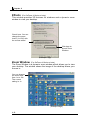
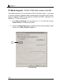
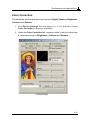
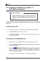
1
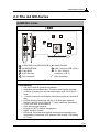
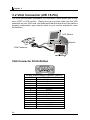
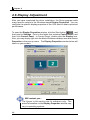
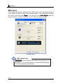
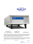
USER’S GUIDE
Version 2.0
Oct. 2002
G52-V1NG403
2-i
i
FCC-B Radio Frequency Interference Statement
This equipment has been tested and found to comply with the limits for a
class B digital device, pursuant to part 15 of the FCC rules. These limits are
designed to provide reasonable protection against harmful interference when
the equipment is operated in a commercial environment. This equipment
generates, uses and can radiate radio frequency energy and, if not installed
and used in accordance with the instruction manual, may cause harmful
interference to radio communications. Operation of this equipment in a residential area is likely to cause harmful interference, in which case the user will
be required to correct the interference at his own expense.
Notice 1
The changes or modifications not expressly approved by the party responsible for compliance could void the user’s authority to operate the equipment.
Notice 2
Shielded interface cables and A.C. power cord, if any, must be used in order
to comply with the emission limits.
VOIR LA NOTICE D’INSTALLATION AVANT DE RACCORDER AU
RESEAU.
ii
8860
8861
8863
8866
8867
8870
8871
8872
8873
8878
8882
8884
8886
8888
8889
8894
Copyright Notice
The material in this document is the intellectual property of MICRO-STAR
INTERNATIONAL. We take every care in the preparation of this document, but
no guarantee is given as to the correctness of its contents. Our products are
under continual improvement and we reserve the right to make changes
without notice.
Trademarks
All trademarks are the properties of their respective owners.
h Intel® and Pentium® are registered trademarks of Intel Corporation.
h PS/2 and OS/2 are registered trademarks of International Business
Machines Corporation.
h Windows® 95/98/2000/NT/XP are registered trademarks of Microsoft
Corporation.
h Open GL® / DirectX® / DirectDraw® / Direct3D® / DirectVideo® /
DirectActiveX® are registered trademarks of Microsoft Corporation.
h Netware® is a registered trademark of Novell, Inc.
h Award® is a registered trademark of Phoenix Technologies Ltd.
h AMI® is a registered trademark of American Megatrends Inc.
h nVIDIA® / nfiniteFXTM is a registered trademark of nVIDIA Corporation.
Macrovision Corporation Product Notice
This product incorporates copyright protection technology that is protected by
method claims of certain U.S. patents and other intellectual property rights
owned by Macrovision Corporation and other right owners. Use of this copyright protection technology must be authorized by Macrovision Corporation,
and is intended for home and other limited viewing uses only unless otherwise authorized by Macrovision Corporation. Reverse engineering or disassembly is prohibited.
Revision History
Revision
Date
V 1.0
V 2.0
September
October
2002
2002
iii
Important Safety Precautions
Always read and follow these basic safety precautions carefully when handling
any piece of electronic component.
1.
Keep this User’s Manual for future reference.
2. Keep this equipment away from humidity.
3. Lay this equipment on a stable, flat surface before setting it up.
4. The openings on the enclosure are for air convection, hence they
protect the equipment from overheating.
5. Make sure the voltage of the power source and adjust properly
110/220V before connecting the equipment to the power inlet.
6. Place the power cord in a way that people are unlikely to step on
it. Do not place anything on the power cord.
7.
Always Unplug the Power Cord before inserting any add-on card
or module.
8.
All cautions and warnings on the equipment should be noted.
9.
Never pour any liquid into the opening that could damage the
equipment or cause an electrical shock.
10. If any of the following situations arise, get the equipment checked
by a service personnel:
The power cord or plug is damaged
Liquid has penetrated into the equipment
The equipment has been exposed to moisture
The equipment has not functioned properly or in accordance
with the User’s Guide
The equipment was dropped and damaged
The equipment has obvious signs of breakage
11. DO NOT LEAVE THE EQUIPMENT IN AN UNCONDITIONED
ENVIRONMENT WITH A STORAGE TEMPERATURE OF 600 C
(1400F) OR ABOVE. IT MAY DAMAGE THE EQUIPMENT.
iv
CONTENTS
Chapter 1 Getting Started
1.1 How to Use this Guide .................................................................. 1-2
1.2 Conventions of this Guide ............................................................ 1-3
Chapter 2 Introduction
2.1 System Requirements ................................................................... 2-2
2.2 The G4 Ti-Series ........................................................................... 2-3
2.3 The G4 MX-Series ....................................................................... 2-39
Chapter 3 Hardware Installation
3.1 Card Installation ............................................................................ 3-2
3.2 VGA Connector (DB 15-Pin) .......................................................... 3-4
3.3 Digital Panel Connector (DVI-I) .................................................... 3-5
3.4 TV_Out Connector (C) ................................................................... 3-6
3.5 TV_Out Connector (S) ................................................................... 3-6
3.6 Video_In Connector (C) ................................................................ 3-7
3.7 Video_In Connector (S) ................................................................ 3-7
3.8 TV_Out Connector (S & C) ............................................................ 3-8
3.9 TV_Out / Video_In Connector (S & C) ........................................... 3-9
Chapter 4 Software Installation
4.1 Installing the VGA Card Drivers .................................................... 4-2
4.2 Installing nVIDIA Capture Driver ................................................... 4-5
4.3 Installing Optional Software .......................................................... 4-6
4.4 Browsing the Web ......................................................................... 4-6
4.5 More Information ........................................................................... 4-7
4.6 Display Adjustment ....................................................................... 4-8
Chapter 5 MSI Live Update 2
5.1 Installing the MSI Live Update 2 with MSI Live Monitor ................ 5-2
5.2 Using the MSI Live Update 2 ........................................................ 5-3
5.3 Live VGA Driver Update ................................................................. 5-4
5.4 Live VGA BIOS Update .................................................................. 5-8
5.5 Live Utility .................................................................................... 5-14
5.6 How to Use the MSI Live Monitor ................................................ 5-15
5.7 Contact Us .................................................................................. 5-22
5.8 Twin-BIOS™ (Optional) ............................................................... 5-23
Chapter 6 Troubleshooting
6.1 General Help ................................................................................. 6-2
6.2 Display Problem ........................................................................... 6-3
v
Νοτε
vi
1
GETTING STARTED
This user’s guide is designed for a series of VGA
cards. Read this chapter first, and it will give you a
clear instruction on how to use this guide.
1-1
Chapter 1
1.1 How to Use this Guide
This user’s guide is designed for a series of VGA cards. Before you start
reading this guide, find out the product name of the VGA card you have just
purchased on the gift box, and look for the specification and function description in next chapter in accordance with the product name of your VGA card .
Chapter 2, INTRODUCTION, provides the brief specification and function of
each VGA card. For detailed description of all functions, you may refer to the
rest of the chapters. Note that the VGA card you purchased may not cover all
functions mentioned herein; therefore, it is recommended to read the “Reference” information first, which indexes the correspoding founction description
of each different VGA card, and then find the proper function description for
your VGA card in the other chapters.
Chapter 3, HARDWARE INSTALLATION, tells you how to install your VGA card
into your computer correctly, and the function of each connector on the VGA
card. Also note that your VGA card may not cover all functions mentioned in
this chapter. Check on Chapter 2, INTRODUCTION, for the specification of
the VGA card you purchased if you have any problem finding the proper function description for your card.
Chapter 4, SOFTWARE INSTALLATION, describes how to install MSI VGA
card software for Windows XP, 98, Me, 2000, or NT, including the driver and
useful utilities.
Chapter 5, MSI LIVE UPDATE 2, a useful utility for you to upgrade your MSI
mainboard and VGA card. Because of this powerful capacity of this utility, you
are allowed to easily download and automatically upgrade the BIOS and the
up-to-date drivers on-line, without spending extra time on searching Web
sites to find the desired BIOS or drivers.
Chapter 6, TROUBLE SHOOTING, provides you the general methods to solve
problems that might happen to your system or VGA card.
1-2
Getting Started
1.2 Conventions of this Guide
Read the conventions of this guide, and it will give you an idea about how this
guide is designed and how this guide should be used.
The product name
of the VGA card
G4Ti4200- DT
Layout
The layout of the
VGA card
The components
on the VGA card
nVIDIA GeForce4 Ti4200 GPU
128MB DDR RAM
VGA Flash BIOS
AGP Interface
Fan connector
DVI-I connector
TV_Out Connector (S & C)
VGA port
Video Encoder
The package contents of this VGA
card
Features
General Features
The specifications
of the VGA card
Important information that should be
paid attention to
.
Package Contents
The nVIDIA nfiniteFXTM II Engine enable a virtually infinite
Unpack
the
package
number of special effects that deliver the next
leap in
realism
to and inspect all the items carefully. If any item
contained is damaged or missing, please contact your local dealer
3D graphics
as soon as possible. Also, keep the box and packing materials in
Dual programmable Vertex Shaders
case you need to ship the unit in the future.
Advanced programmable Pixel Shaders
nVIDIA Lightspeed Memory ArchitectureTM II
Your VGA card package should contain the following items:
nVIDIA AccuviewTM Antialiasing
3D Textures
Shadow Buffers
4 dual-rendering pipelines
VGA Card
8 texels per clock cycle
Dual cube environment mapping
High-Definition Video Processor (HDVP)
AGP 4X with Fast Writes
Software Pack Cds
AGP 4X / 2X and AGP Texturing support
MSI reminds you...
Users' Manual
The Display Modes listed above are for your reference; the
actual settings may be different on your system because of
using different monitors.
Corresponding function for
each particular VGA card
Reference
2. Introduction.......................................................................2-1
3. Hardware Installation
3.1 Card Installation...........................................................3-2
3.2 VGA Connector (DB 15-Pin)............................................3-4
3.3 Digital Panel Connector (DVI-I).......................................3-5
3.5 TV_Out Connector (S).................................................... 3-6
4. Software Installation........................................................... 4-1
5. MSI Live Update 2
5.1 Installing the MSI Live Update 2 with MSI Live Monitor......... 5-2
5.2 Using the MSI Live Update 2 ........................................... 5-3
5.3 Live VGA Drive Update...................................................5-4
5.4 Live VGA BIOS Update....................................................5-8
5.5 Live Utility....................................................................5-14
5.6 How to Use the MSI Live Monitor.....................................5-15
5.7 Contact Us..................................................................5-22
5.8 Twin-BIOS (Optional).....................................................5-23
6. Troubleshooting..................................................................6-1
1-3
Chapter 1
Νοτε
1-4
2
INTRODUCTION
This chapter provides the brief specification and
function of each VGA card. For detailed description of all functions, you may refer to the rest of the
chapters. Note that the VGA card you purchased
may not cover all functions mentioned herein;
therefore, it is recommended to read the “Reference” information first, which indexes the
correspoding founction description of each different VGA card, and then find the proper function
description for your VGA card in the other chapters.
2-1
Chapter 2
2.1 System Requirements
To install the VGA card, your system needs to meet the following requirements:
2-2
Computer
Intel® Pentium II/III/4 processor,
Intel® Celeron processor, or
compatible system
Expansion Slot
AGP slot
Monitor
VGA support, minimum 640 x 480
resolution
Operating System
Windows® 98/ME, Windows® NT 4.0,
Windows® 2000, XP
CD-ROM Drive
Double Speed or Higher
Introduction
2.3 The G4 MX-Series
G4MX440-VTD8X
Layout
nVIDIA GeForce4 MX440 8X GPU
64 MB DDR RAM
Flash-BIOS
AGP Interface
Fan connector
Video Decoder
VGA Connector (DB 15-Pin)
TV_Out / Video In
connector (S & C)
DVI-I Connector
Features
Performance
256-bit 3D and 2D graphics accelerator
Integrated second-generation Transform and Lighting engines
34 million triangles per second setup engine with Z-cull and Zclear
1.1 billion texels per second and 540 million pixels per second fill
rate
nVIDIA Shading Rasterizer with 24 of 26 DX8 pixel shading
functions and full set of OpenGL 1.3 pixel combiner operations
32-bit color with 32-bit z/stencil
Cube environment mapping
DirectX and S3TC texture compression
Digital Vibrance Control
Enhanced TwinView dual-display architecture supporting any
combination of notebook LCD, desktop VGA monitor, DVI display
or TV set
2-39
Chapter 2
Features
Dual CRTC/Simultaneous Dual Display (same or different
surfaces)
Integrated dual LVDS Transmitter supporting LCD panels up to
2048x1536
Integrated 350 MHz Palette-DAC for analog VGA monitors up to
2048x1536
Integrated NTSC/PAL TV encoder supporting resolutions up to
1024x768
Integrated TMDS transmitter for Digital Visual Interface support
with scaling and filtering for flat panels up to 1600x1200
DVD- and HDTV-ready MPEG-2 decoding up to 1920x1080i ATSC
format
MPEG-2 hardware decode, including Inverse Discrete Cosine
Transform and Motion Compensation
Compatibility
Supports VIP1.1 interface
Supports Microsoft DirectX 8.1, 8.0, 7.0, 6.0, and 5.0 (IDCT)
Fully compliant support for OpenGL 1.3 for all Windows operating
systems
Up to 8.8 GB/second memory bandwidth
Up to 2.1 GB/second AGP bus bandwidth
Supports 128-bit DDR, 64-bit DDR, and 32-bit DDR SDRAM
Supports Super High Resolution Graphics Modes
640x480
800x600
1024x768
1152x864
1280x1024
1600x1200
1920x1200
2048x1536
8/16/32
8/16/32
8/16/32
8/16/32
8/16/32
8/16/32
8/16/32
8/16/32
bit colors with 150Hz
bit colors with 150Hz
bit colors with 120Hz
bit colors with 120Hz
bit colors with 100Hz
bit colors with 85Hz
bit colors with 75Hz
bit colors with 60Hz
MSI reminds you...
Ø The Display Modes listed above are for your reference; the
actual settings may be different on your system because of
using different monitors.
Ø Note that nView of lower VGA connector or TV-out connector
is not available in version 1.00. Please use upper VGA
connector or TV-out connector for nView.
2-40
Introduction
Package Contents
Unpack the package and inspect all the items carefully. If any item contained is damaged or missing, please contact your local dealer as soon as
possible. Also, keep the box and packing materials in case you need to
ship the unit in the future.
Your VGA card package should contain the following items:
VGA card
Software
Pack CDs
TV-Out / Video_In
1-to-4 connector
DVI-I / VGA
adapter
User’s Manual
Reference
2. INTRODUCTION ............................................................................ 2-1
3. HARDWARE INSTALLATION ........................................................ 3-1
3.1 Card Installation ..................................................................... 3-2
3.2 VGA Connector (DB 15-Pin) ................................................. 3-4
3.3 Digital Panel Connector (DVI-I) ............................................ 3-5
3.9 TV_Out / Video_In Connector (S&C) .................................... 3-9
4. SOFTWARE INSTALLATION ......................................................... 4-1
5. MSI LIVE UPDATE 2 ....................................................................... 5-1
5.1 Installing MSI Live Update 2 with MSI Live Monitor .............. 5-2
5.2 Using the MSI Live Update 2 .................................................. 5-3
5.3 Live VGA Drive Update .......................................................... 5-4
5.4 Live VGA BIOS Update .......................................................... 5-8
5.5 Live Utility ............................................................................. 5-14
5.6 How to Use the MSI Live Monitor ......................................... 5-15
5.7 Contact Us ............................................................................ 5-22
6. TROUBLESHOOTING ................................................................... 6-1
2-41
3
HARDWARE
INSTALLATION
This chapter tells you how to install your VGA card
into your computer correctly and the function of
each connector on the VGA card. Note that your
VGA card may not cover all functions mentioned in
this chapter. Check on Chapter 2, INTRODUCTION, for the specification of the VGA card you purchased if you have any problem finding the proper
function description for your card.
3-1
Chapter 3
3.1 Card Installation
To install the VGA card to your computer, please follow the steps below:
3.1.1 Installation on new system
1.
Remove the computer case.
2.
Locate the AGP slot on your mainboard.
MSI reminds you...
Inserting your VGA card into a wrong type of slot (e.g.
PCI slot) will damage your card (refer to your
mainboard manual for more information).
3.
Put the card directly over the AGP slot and press one end of the card
into the slot first. Slightly but firmly press the other end until it is fully
seated in the slot.
4.
Secure the card with a bracket screw.
5.
Install all other cards and devices and connect all the cables, and
then replace the case.
6.
Connect the monitor. Now, you are ready to install the software on
your computer.
Bracket screw
VGA card
*The appearance may
be different by different
models
AGP slot
Mainboard
3-2
Hardware Installation
3.1.2 Installation on system with existing VGA card
To replace the existing VGA card to your computer, please follow the steps
below:
1.
If your operating environment is Windows® NT system, switch your
display driver to standard VGA first (refer to Windows® NT documentation for more information). If you are using Windows® 98/ME/2000,
skip this step.
2.
Turn off the computer and unplug all the cables and power cords.
3.
Remove the computer case.
4.
Remove the existing VGA card. Locate the AGP slot on your mainboard.
MSI reminds you...
Inserting your VGA card into a wrong type of slot (e.g.
PCI slot) will damage your card (refer to your
mainboard manual for more information).
5.
Put the card directly over the AGP slot and press one end of the card
into the slot first. Slightly but firmly press the other end until it is fully
seated in the slot.
6.
Secure the card with a bracket screw.
7.
Replace the case.
8.
Connect the monitor (see previous section).
9.
Restart the computer. Now, you are ready to install the driver for the
VGA card.
3-3
Chapter 3
3.2 VGA Connector (DB 15-Pin)
The VGA card provides a standard VGA connector, which allows you to connect a CRT or LCD monitor. Simply plug your monitor cable into the VGA
connector on your VGA card, and make sure that the other end of the cable is
properly connected to your monitor (refer to your monitor manual for more
information.)
LCD Monitor
CRT Monitor
OR
VGA Connector
VGA Connector Pin Definition
5
1
15
11
Analog Video Display Connector (DB15-S)
Pin
Signal Description
1
Red
2
Green
3
Blue
4
Not used
5
Ground
6
Ground
7
Ground
8
Ground
9
5V
Ground
10
11
Not used
12
SDA
13
Horizontal Sync
14
Vertical Sync
15
SCL
3-4
Hardware Installation
3.3 Digital Panel Connector (DVI-I)
The VGA card provides a DVI (Digital Visual Interface) connector which allows you to connect an LCD monitor. The DVI connector provides a highspeed digital interconnection between the computer and its display device.
To connect a LCD monitor, simply plug your monitor cable into the DVI connector on the VGA card, and make sure that the other end of the cable is
properly connected to your monitor. (refer to your monitor manual for more
information.)
DVI connector
LCD Monitor
DVI-I Connector Pin Definition
1
17
8
24
DVI-I Connector
Pin
1
2
3
4
5
6
7
8
9
10
11
12
C1
C2
C3
Signal Assignment
T.M.D.S.* Data2T.M.D.S. Data2+
T.M.D.S. Data2/4 Shield
T.M.D.S. Data4T.M.D.S. Data4+
DDC Clock
DDC Data
N/C
T.M.D.S. Data1T.M.D.S. Data1+
T.M.D.S. Data1/3 Shield
T.M.D.S. Data3-
Pin
13
14
15
16
17
18
19
20
21
22
23
24
Analog Red
Analog Green
Analog Blue
C4
C5
Signal Assignment
T.M.D.S. Data3+
+5V
GND (for +5V)
Hot Plug Detect
T.M.D.S. Data0T.M.D.S. Data0+
T.M.D.S. Data0/5 Shield
T.M.D.S. Data5T.M.D.S. Data5+
T.M.D.S. Clock Shield
T.M.D.S. Clock+
T.M.D.S. ClockAnalog Horizontal Sync
Analog Ground (analog
R, G & B return
*T.M.D.S. Technology
The graphics data sent to the digital monitor use Transition Minimized Differential
Signaling (T.M.D.S.)technology. TMDS uses an encoding algorithm to 8-bits of data
into a 10-bit transition minimixed, DC balanced character, which are transitionminimized to reduce EMI with copper cables and DC-balanced for transmission over
fiber optic cables. The TMDS algorithm also provides robust clock recovery for
greater skew tolerance with longer cables or low cost short cables.
3-5
Chapter 3
3.4 TV_Out Connector (C)
The VGA card provides a TV_Out connector for video-out function which allows you to output the image to a TV or video device. Simply plug one end of
the RCA cable into the TV_Out connector on the VGA card, and the other end
to the video input connector on your TV or video device. Most TVs and video
devices support such kind of input connector. For the correct connection,
please refer to the TVs and video devices' manuals for more information.
TV_Out
Connector (C)
TV
Projector
3.5 TV_Out Connector (S)
The VGA card provides a TV_Out connector for video-out function which allows you to output the image to a TV or video device. Simply plug one end of
the S_Video cable into the TV_Out connector on the VGA card, and the other
end to the video input connector on your TV or video device. Some TVs and
video devices may support such kind of input connector. For the correct
connection, please refer to the TVs and video devices' manuals for more
information.
TV_Out
Connector (S)
TV
Projector
3-6
Hardware Installation
3.6 Video_In Connector (C)
The VGA card provides a Video _In connector for video-in function which
allows you to input the image from video devices. Simply plug one end of the
RCA cable into the Video_In connector on the VGA card, and the other end to
the video output connector on your video devices. Most video devices support
such kind of output connector. For the correct connection, please refer to the
video devices' manuals for more information.
DVD/VCD
player
Video_In
Connector (C)
Video player
Video camera
Digital camera
3.7 Video_In Connector (S)
The VGA card provides a Video_In connector for video-in function which allows you to input the image from video devices. Simply plug one end of the
S_Video cable into the Video_In connector on the VGA card, and the other
end to the video output connector on your video devices. Some video devices
may support such kind of output connector. For the correct connection, please
refer to the video devices' manuals for more information.
Video_In
Connector (S)
DVD/VCD
player
Video player
Video camera
3-7
Chapter 3
3.8 TV_Out Connector (S & C)
The VGA card provides a 9-pin TV_Out connector (S & C) for video-out function which allows you to output the image to a TV or video device. This type of
connector can be used for either RCA cable or S_Video cable if the attached
TV-Out 1-to-2 connector is plugged in. Simply plug one end of the RCA cable
or S_Video cable into the proper connector provided by the TV-Out 1-to-2
connector, and the other end to the video input connector on your TV or video
device. Most TVs and video devices support such kind of input connector. For
the correct connection, please refer to the TV’s and video devices' manuals
for more information.
TV_Out
Connector (S & C)
TV
TV-Out 1-to-2
connector
3-8
Projector
Hardware Installation
3.9 TV_Out / Video_In Connector (S & C)
The VGA card provides a 9-pin TV_Out / Video_In connector (S & C) for videoout / video-in function which allows you to output / input the image to / from a
TV or video device. This type of connector can be used for either RCA cable
or S_Video cable if the attached TV-Out / Video_In 1-to-4 connector is plugged
in. Simply plug one end of the RCA cable or S_Video cable into the proper
connector provided by the TV-Out / Video_In 1-to-4 connector, and the other
end to the video input / output connector on your TV or video device. Most TVs
and video devices support such kind of input / output connector. For the
correct connection, please refer to the TV’s and video devices' manuals for
more information.
DVD/VCD
player
TV_Out
Connector (S & C)
Video player
Video camera
TV-Out / Video_In
1-to-4 connector
Digital camera
TV
Projector
3-9
Chapter 3
Νοτε
3-10
4
SOFTWARE
INSTALLATION
This chapter describes how to install MSI VGA card
software for Windows XP, 98, Me, 2000, or NT,
including the driver and useful utilities.
4-1
Chapter 4
4.1 Installing the VGA Card Driver
4.1.1 The Driver for Windows® 98/ME
To install the driver for the VGA card to your computer running Windows® 98/
ME, please follow the steps below:
1. Turn on the computer.
2. Insert the CD into the CD-ROM drive. The Autorun program will start
the Setup program, and show the setup screen as follows:
MSI reminds you...
Ø If, on your computer, the “Autorun” program does
not run automatically, please 1) enable the CDROM drive’s auto-detect function from Control
Panel; or 2) find and run the setup.exe manually
from the CD-ROM.
Ø The figures in this section are based on the tested
platform and for reference only; the actual displays
and information (such as settings, driver’s version,
etc.) on your system may be different.
4-2
Software Installation
3. Click nVIDIA VGA Drivers. Follow the on-screen instructions to complete the installation.
4. After finishing the installation, restart the computer as instructed.
4.1.2 The Driver for Windows® XP/2000/NT
MSI reminds you...
For Windows® NT 4.0 users, “Service Pack 3” or later version must be installed before installing the driver.
To install the driver for the VGA card to your computer running Windows®
2000/XP/NT, please follow the steps below:
1. Turn on the computer.
2. Insert the CD-ROM provided into the CD-ROM drive. The Autorun program will start the Setup program and show the setup screen as
shown below:
4-3
Chapter 4
MSI reminds you...
If, on your computer, the Autorun program does not execute automatically, please 1) enable the CD-ROM drive’s
auto-detect function from Control Panel; or 2) find and run
the setup.exe file manually from the CD-ROM.
3. Click nVIDIA VGA Drivers. Follow the on-screen instructions to complete the installation.
MSI reminds you...
Under Windows® 2000, the Digital Signature Not Found
dialog box (as shown below) will pop up during the
installation. Press Yes to continue the installation.
4. After finishing the installation, restart the computer as instructed.
4-4
Software Installation
4.2 Installing nVIDIA Capture Driver
The VGA card provides a video-in function that allows you to connect the
external video devices for images capture function. With this driver installed,
you can capture the images on your computer through the video input port on
the card.
1. Turn on the computer.
2. Insert the CD into the CD-ROM drive and enter the Setup program.
3. In the MSI Installation dialog box, click nVIDIA Capture Drivers. Follow the on-screen instructions to complete the installation.
4. After finishing the installation, restart the computer as instructed.
4-5
Chapter 4
4.3 Installing Optional Software
After restarting the computer, you can install the optional software from the
CD-ROM provided, such as Microsoft DirectX 8.0, Adobe Acrobat Reader,
and MSI 3D Turbo Experience. Simply click to select the button and follow the
on-screen instructions to complete the installation.
1. Insert the CD into the CD-ROM drive, and start the Setup program.
2. Choose the Drivers tab on the setup screen.
3. Click the software’s button that you want to install, then follow the onscreen instructions to complete the installation.
4.4 Browsing the Web
Since our products are under continual improvement, there may be a later
version of the driver and BIOS for your purchase. We encourage you to visit
our website at http://www.msi.com.tw to get the latest news. In addition, we
post lots of useful websites on the World Wide Web for you. Simply click to
select the linkage and browse the website as you usually do.
1. Insert the CD into the CD-ROM drive, and start the Setup program.
2. Choose the WebSite tab on the setup screen.
3. Click the corresponding button to launch your browser and
access the website.
MSI reminds you...
To surf these websites, you have to make connection to
the Internet first.
4-6
Software Installation
4.5 More Information
To browse through the contents on the CD, simply click Browse CD under
each tab. You can use the Manual tab to learn more about your MSI
products.
1. Insert the CD into the CD-ROM drive and start the Setup program.
2. Click About CD to learn more about the CD-ROM.
3. Choose the Manual tab on the setup screen.
4. Click the corresponding button to get more information.
4-7
Chapter 4
4.6 Display Adjustment
After you have completed the driver installation, the Setup program adds
many specific options to the Windows-based Display Properties. You can
configure the specific display properties of the VGA card to obtain optimized
performance.
To open the Display Properties window, click the Start button
, and
then point to Settings. Point to the folder that contains Control Panel, and
then click Control Panel. In Control Panel, double-click the Display icon.
Also, you may simply right-click the blank Windows® desktop area and choose
Properties in the pop-up menu. The Display Properties window below will
show on your screen:
MSI reminds you...
The figures in this section are for reference only. The
actual information on the Display Properties window may
vary in operating systems.
4-8
Software Installation
In this section, we list the most important information on how to configure
these specific options of the VGA card.
Display Settings
Open the Display Properties window as instructed earlier, and click the Settings tab, and then you will see the figure as shown in p. 3-7. This screen
shows information of the display adapter, colors, range of display area, and
refresh rate.
MSI Information
This screen shows the detailed information of the VGA card, including the
model name, display mode, version of the driver and BIOS, memory size,
AGP mode and so on.
(Example Page)
4-9
Chapter 4
MSI Clock
This screen shows the settings of the VGA card’s core clock and memory
clock, and it provides you the overclocking function. Move the slider to adjust
the value, and then click Apply
Apply. You can also click Auto Adjust ,and the
proper memory clock will be set for your VGA card automatically.
(Example Page)
MSI reminds you...
WARNING: Overclocking may cause the display to be
abnormal. It is recommended to use the Default settings
for the most stable performance.
4-10
Software Installation
GPU Information
This screen shows the detailed information of GPU used on your VGA card,
including the bus type, BIOS version, memory size and so on.
(Example Page)
Click here
Click Additional Properties to access further settings on Direct3D and
OpenGL.
Direct3D Settings
This tab allows you to adjust the values of Performance and CompatOptions, Mipmapping and PCI Texture Memory Size for
ibility Options
your 3D games.
4-11
Chapter 4
Performance and Compatibility Options
This option contains many items that allow you to set up the options influencing the performance and compatibility in your 3D games.
Mipmapping
This option allows you to set up the mipmapping level for a higher performance or better image effects.
Click here
(Example Page)
PCI Texture Memory Size
This option allows you to adjust the size of the PCI texture memory. For some
applications using the Direct3D technology, typing a higher value in this spin
box may significantly increase the performance. However, this option does
not work on the display adapter using an AGP bus.
Click More Direct3D to gain access to additional settings of Direct3D.
Texel Alignment
This option allows you to change the addressing scheme of hardware texture
for texel. Move the slider to adjust the value, which will change the texel origin
between the upper-left corner and the center position.
4-12
Software Installation
OpenGL Settings
This tab allows you to adjust the Performance and Compatibility Options for
your OpenGL application.
Performance and Compatibility Options
This option contains many items that allow you to set up the options influencing the performance and compatibility in your OpenGL application.
Default Color Depth for Textures
This option allows you to choose the default color depth for texture.
(Example Page)
Buffer Flipping Mode
When running the OpenGL application under the Full-Screen mode, turning
on the page flipping function may significantly increase the performance.
Vertical Sync
This option allows you to choose the type of vertical sync.
Full Scene Antialiasing Method
This option allows you to choose the method of full scene antialiasing.
4-13
Chapter 4
nView (For GeForce 4-Series or later)
If your VGA card is equipped with a TV-Out connector, you can use a second
output device (for example, a TV or a computer monitor) as a part of your
operating desktop --- extending your desktop to the second device or copying
your desktop onto the second device.
Copying the Desktop (For GeForce 4-Series or later)
When the second video output device (TV or monitor) is connected:
1. Open the Display Properties window.
2. Under the Settings tab, click Advanced, and then choose the nView
tab.
3. Click Clone, and then Apply to enable the function, or OK to accept and
exit the setup screen.
Click here
(Example Page)
4-14
Software Installation
Extending the Desktop (For GeForce 4-Series or later)
When the second video output device (TV or monitor) is connected:
1. Open the Display Properties window.
2. Under the Settings tab, right-click the second device icon on the main
screen, and choose Enabled in the pop-up menu.
3. Click the Extend my Windows desktop onto this monitor check box
as the default value.
4. Click Apply to enable the function, or OK to accept and exit the setup
screen.
2
3
4
4
(Example Page)
MSI reminds you...
When the extending function is enabled, you can move
your mouse, place the icons and show program windows
on the second device. However, some programs do not
support this function. If your program stops running completely or intermittently when using more than one monitor,
please disable the function.
4-15
Chapter 4
Setting the nView (For GeForce 4-Series or later)
You can configure the extended desktop for your perference and convenience.
You can enter the nView Settings window from two ways.
From the blank desktop:
1. Right-click the blank desktop and the pop-up window will show on the
screen as following:
Click here
(Example Page)
2. Click the nView Settings to open the setting window.
From Start button:
1. Click the Start button
, and then point to Settings.
2. Point to the folder that contains Control Panel, and then click Control
Panel.
3. In Control Panel, double-click the nView icon.
4-16
Software Installation
Profiles
(For GeForce 4-Series or later)
This window allows you to load your previous settings or to save the current
settings.
You can load your
previous settings
(Example Page)
Windows (For GeForce 4-Series or later)
This window allows you to control the windows shown on the screen. You are
also allowed to set the monitor in which the dialog box or an applocation will
show.
You can assign the
monitor in which the
dialog boxes will
show
(Example Page)
4-17
Chapter 4
Effects
(For GeForce 4-Series or later)
This window provides 3D features for windows and a dynamic zoom
window to view your desktop.
Check here. You can
change the zoom
levels (1x-10X) with
the mouse wheel
Click here to
launch Zoom
Window
(Example Page)
Zoom Window
(For GeForce 4-Series or later)
The Zoom Window is a dynamic zoom window which allows you to view
your desktop. The window shows the image of the desktop where your
mouse is.
You can change
the zoom level
from 1x to 10x.
The current
setting is 1x.
(Example Page)
4-18
Software Installation
Hot Keys
(For GeForce 4-Series or later)
This window provides a personalized setting which allows you to execute an
action with just one click on your keyboard. The hot key can be a key
combination.
Select an action
that you would
like to set a hot
key for
Set a hot key for
the action
selected
(Example Page)
Desktops
(For GeForce 4-Series or later)
This window allows you to create up to 32 different desktops. You can
shift your desktops between them.
The desktops can
be loaded from
the wallpaper
liberary
(Example Page)
4-19
Chapter 4
TV Mode Support: NTSC, NTSC-EIA (Japan) and PAL
The default setting for TV-out function is PAL (for Europe region). If you want
to use this function in different areas, please adjust to a proper mode accordingly (for example, NTSC for the regions of Taiwan and USA). Otherwise, the
display on TV may be abnormal.
1. Click Device Settings (see the figure in p. 3-13), and then choose
Output Device in the pop-up window.
2. Under the Output Device tab, click TV and then select a proper output
format in the Video Output Format box.
Click
here
(Example Page)
4-20
Software Installation
Color Correction
This tab allows you to adjust the proper values of Digital Vibrance, Brightness,
Contrast and Gamma.
1. Click Device Settings (see the figure in p. 3-13), and then choose
Color Correction in the pop-up window.
2. Under the Color Correction tab, move the slider to set up a value from
a continuous range in Brightness, Contrast and Gamma.
(Example Page)
4-21
Chapter 4
Screen Adjustment
This tab allows you to adjust the proper position of the display image.
1. Click Device Settings (see the figure in p. 3-13), and then choose
Screen Adjustment in the pop-up window.
2. Click the UP ARROW
and RIGHT ARROW
, LEFT ARROW
keys to configure the position of the image.
(Example Page)
4-22
, DOWN ARROW
Software Installation
Νοτε
4-23
Chapter 4
Νοτε
4-24
5
MSI LIVE UPDATE 2
MSI LIVE UPDATE 2, a useful utility for you to upgrade your MSI mainboard and VGA card. Because
of this powerful capacity of this utility, you are allowed to easily download and automatically upgrade the BIOS and the up-to-date drivers on-line,
without spending extra time on searching Web
sites to find the desired BIOS or drivers.
Moreover, MSI LIVE UPDATE 2 supports multi-language interfaces, and be capable of detecting the
language of your operation system while installing this program. Users will soon find out that
once MSI LIVE UPDATE 2 is installed successfully,
the language of its interface will be the same as
your OS if only the language is supported.
5-1
5-1
Chapter 5
5.1 Installing the MSI Live Update 2
with MSI Live Monitor
MSI reminds you...
Before installing the MSI Live Update 2 with MSI Live
Monitor, it is recommended to uninstall other version
of MSI Live Update to avoid problems occurred to your
system.
To use this feature, you have to install the program first. You can download
the program from: 1) the software pack CDs in the package; or 2) the MSI
Web site.
Installing from CDs
1. Insert the CD into the CD-ROM drive, and start the Setup program.
2. Click the Utility tab on the setup screen.
3. Click MSI Live Update 2. Follow the on-screen instructions to complete the installation.
Installing from the MSI Web site
1. Make connection to the MSI’s Web site at http://www.msi.com.tw
2. Select /Support/Live Update 2/ on the upper of the MSI’s homepage to
enter the setup page.
InstallShield Wizard button to have the program of
3. Click the
MSI Live Update with MSI Live monitor downloaded and installed on
your system automatically, or click here (manual) to download and
install the program manually.
4. Follow the on-screen instructions to complete the installation.
5-2
MSI Live Update 2
5.2 Using the MSI Live Update 2
After the installation is completed, you can launch the MSI Live Update 2 by
1) double-click the MSI Live Update 2 icon
on the desktop; or 2) click the
, and then point to Programs / MSI / Live Update 2. The
Start button
setup screen should appear as shown below, which contains five main selections on the left of the page: Live BIOSTM, Live DriverTM, Live VGA BIOSTM,
Live VGA DriverTM, and Live UtilityTM.
MSI reminds you...
The Live BIOS and Live Driver options are used for
MSI mainboards, and the Live VGA BIOS and Live
VGA Driver options are used for your MSI VGA cards.
5-3
Chapter 5
5.3 Live VGA Driver Update
1. To update the MSI Live VGA Driver, click Live VGA Driver on the left
column of the main page.
Click here
MSI reminds you...
The model name and driver/BIOS version appear in
the instruction are for reference only; the actual result
should depend on the card you installed.
2. This utility will start checking your platform and the information on the
VGA card, and display the information in a list:
Click here
5-4
MSI Live Update 2
3. Click the graph button at the bottom to connect to the MSI Live Update
Series Server. It will automatically connect to the Internet and compare the version of the driver in the database.
4. It may take several minutes to detect the required drivers. Please wait
while proceeding detection.
5. The results are displayed as shown below:
Supported driver not found
Supported driver found
5-5
Chapter 5
6. Click the InstallShield Wizard button
on the right side of the
table to download and update the driver. All actions will proceed
automatically.
7. Follow the on-screen instructions to complete the updating procedure.
Select a folder to save the driver file
Click Next to start installing the VGA Driver
5-6
MSI Live Update 2
MSI reminds you...
1. Always click Yes in the Internet Explorer dialog
box below.
2. Click Yes in the Security Warning dialog box.
5-7
Chapter 5
5.4 Live VGA BIOS Update
1. To update the MSI Live VGA BIOS, click Live VGA BIOS on the left of the
main page.
Click here
2. If your VGA card does not support the Live VGA BIOSTM function, you
will receive a warning message on the screen.
3. If your VGA card do support the Live VGA BIOSTM function, please pay
attention to the message shown on the screen telling you that in what
circumstance flashing BIOS may fail to reboot.
4. Click Yes if you would like to try it at your own risk or No to return the
main page with everything unchanged.
5-8
MSI Live Update 2
Select Yes to continue
Select No to keep
everything unchanged
5. If you click Yes to continue, it will check the information and BIOS
version of your VGA card, and list them in a table:
5-9
Chapter 5
6. Click the graph button at the bottom to connect to the MSI Live Update
Series Server.
7. The MSI Live VGA BIOS will automatically connect to the Internet and
search the supported BIOS in the database of MSI. The following is an
example of the research result:
Supported VGA BIOS not found
Supported VGA BIOS found
5-10
MSI Live Update 2
8. If it has found one (or several) supported BIOS for your VGA card, click
on the right side of the table to
the InstallShield Wizard button
have the new BIOS downloaded and updated automatically.
MSI reminds you...
Your monitor may go BLANK while the software
EEPROM has being erased. Please wait for a while
before you proceed to the next step.
9. Follow the on-screen instructions to complete the updating procedure.
Select a folder to save the BIOS file
Downloading
5-11
Chapter 5
Click Next to continue
It is recommended to close
all programs before
updating new VGA BIOS by
click Close all listed
programs, and then click
Next to continue
5-12
MSI Live Update 2
Click Start to start flashing VGA BIOS
MSI reminds you...
1. Always click Yes in the Internet Explorer dialog
box below.
2. Click Yes in the Security Warning dialog box.
5-13
Chapter 5
5.5 Live Utility
Live UtilityTM is a tool that helps users to get the correct system information,
and generate a list that contents various compatible links of MSI’s softwares
in accordance with the system information been detected.
Click here first
Click here to connect to MSI Live
Update Server.
5-14
MSI Live Update 2
5.6 How to Use the MSI Live Monitor
MSI Live Update 2 comes with a useful utility, MSI Live Monitor, to help users
detecting their system information, and searching for the up-to-date drivers
or BIOS online. To use MSI Live Monitor, follow the instructions shown below.
Auto Search
1. Click the right button of your mouse on the MSI Life Monitor icon
from the window tray at the lower-right corner of the
screen.
2. Select Auto Search from the MSI Life Monitor menu. Select the desired searching process from the Auto Search list, and then click Next
button.
Select Auto Search
Auto Search list
Click Next
5-15
Chapter 5
3. Once you click Next button, the system will start searching your system information.
Searching
Click Finish
Searching
Result
Click the Live VGA BIOS / Live VGA Driver Tag or clilck the
listed items on the page to browse the searched Up-to-date
VGA BIOS/Drivers founded by MSI Live Monitor.
5-16
MSI Live Update 2
4. Click on the item that you would like to download.
Click here to select the item you wish to download
Click here to download the selected item.
4. Follow the on-screen instructions, and the InstallShield Wizard will
lead you to complete downloading and installing the selected new
VGA BIOS/Dirvers.
5-17
Chapter 5
View Last Result
MSI Live Monitor provides a shotcut for users to recall the last search result
more efficiently.
1. Click the right button of your mouse on the MSI Live Monitor icon
from the window tray at the lower-right corner of the
screen.
2. Select View Last Result from the MSI Live Monitor menu.
Select View Last Result
3. The last Searching Result will be recalled at once.
5-18
MSI Live Update 2
Preference
MSI Live Monitor provides a scheduling function for searching for the latest
BIOS/Dirvers on-line automatically in a set period or condition.
1. Click the right button of your mouse on the MSI Live Monitor icon
from the window tray at the lower-right corner of the
screen.
2. Select Preference from the MSI Live Monitor menu.
Select Preference
3. Select Auto Search Setting page by clicking Auto Search Setting on
the left hand side.
Click here
Check this item to
apply the Auto
Search Frequency
setting to all Sub
items under Auto
Seach Setting.
Set your Auto Search Frequency here.
5-19
Chapter 5
4. Users are allowed to set some configuration for MSI Live Monitor if
desried. Select Configuration page by clicking Configuration on the
left hand side.
Click here
Version Filter
Start Up Funcion
MSI News
Color Selections
5. Select About the Support page by clicking About the Support on the
left hand side. In About the Support page, users will be able to learn
the version of your MSI Live Monitor.
Click here
5-20
MSI Live Update 2
FAQ
MSI Live Monitor provides a database which contents various possible questions about MSI’s products for users to inquire.
1. Click the right button of your mouse on the MSI Live Monitor icon
from the window tray at the lower-right corner of the
screen.
2. Select FAQ from the MSI Live Monitor menu.
Select FAQ
3. To find the answers of your questions in MSI FAQ database, you may
select a particular category which is related to your questions, or use
the searching function by giving some key words.
Select the
category which
is related to
your questions
here.
Enter some key
words of your
questions
5-21
Chapter 5
5.7 Contact Us
Users will be able to contact MSI for further information or help by clicking the
Contact us button on the left of the page.
Click here
If you need any technical support, it is strongly recommended to describe the
problem of any kind specifically in the mail sending to MSI, and attach your
system information which will be detected and generated by MSI Live Update
2 if Append System Information is checked.
Check
this item
Click Details to review your system
information below.
5-22
MSI Live Update 2
5.8 Twin-BIOS™ (Optional)
The diagram below describes the procedure in brief:
BIOS I
Return to BIOS I
Run the flash utility
BIOS II
Boot up with BIOS II
Successfully updated!
OOPS! Failed...
5-23
Chapter 5
Our products are under continual improvement, and there may be a later
version of the BIOS to solve the existing problems on displays or the installaton.
When you use the flash utility* to update the BIOS on the card, it is inevitable
that your devices may encounter some unexpected risks, such as power
interruption, during the updating process. If, unfortunately, the updating procedure is failed and the VGA card cannot work anymore --- this powerful
technology can solve your problems!
If you fail to update the BIOS successfully, and have to use this function to
save your VGA card, please follow the steps below:
1. Turn off the power and remove the computer case.
2. Locate the jumper on the VGA card, and set it up to enter the BIOS II
mode (safe mode) when restarting the system.
3. Do not replace the case first and turn on the power.
5-24
MSI Live Update 2
4. With the BIOS II, you should be able to start the system normally. After
entering the operating system (OS), set up the jumper to enter the
BIOS I mode (work mode). Now you can restore the original BIOS or
you can try to update the BIOS using the flash utility* again.
MSI reminds you...
Warning: It is very dangerous to perform the procedure under such condition. To ensure your safety
and prevent electric shocks and damages, please
Do NOT touch any component in the computer.
5. If the updating procedure still failed**, repeat Step 3 and 4. If the
updating procedure is successful, that means the BIOS data is written onto the chip successfully.
6. Replace the case and restart the computer.
MSI reminds you...
* To update the BIOS, you must use the special flash
utility (MSI Live Update Series) provided by MSI only,
which can fully support the Twin-BIOSTM technology.
If the third party’s utility is used in the updating
procedure, it will erase the data in BIOS II.
** If you always encounter problems while updating
the BIOS and driver, check if the mainboard’s chipset
driver was properly installed. Please install the
chipset driver from your mainboard vendor first and
try again.
5-25
Chapter 5
Νοτε
5-26
6
TROUBLESHOOTING
TROUBLE SHOOTING, provides you the general
methods to solve problems that might happen to
your system or VGA card.
6-1
Chapter 6
6.1 General Help
Q: Where can I find more information about my VGA card?
Please visit our Web site at http://www.msi.com.tw
Q: How do I know the driver version of my VGA card? How do I update it?
To know the driver version of your VGA card, simply click the Start
, and then point to Settings. Point to the folder that
button
contains Control Panel, and then click Control Panel.
In Control
Panel, double-click Display to open the Display Properties window
for more information. (Please refer to Chapter 3 Software Installation for details.)
If you need to update your VGA card’s driver, please download the
latest version for your VGA card from our Web site. Usually, the
driver file is an executable (.exe) file. Simply double-click the file
and follow the on-screen instructions to complete the updating
procedure.
6-2
Troubleshooting
6.2 Install InterVideo WinDVR
Q: My monitor displays nothing after the system boots up.
Your VGA card may not be installed correctly. Please check the
installation procedure described in Chapter 2 Hardware Installation.
Make sure that your monitor are connected to the VGA card properly,
and the power is turned on.
Q: The image is of poor quality; the screen image is off-centered, and the
image’s shape becomes deformed.
Your VGA card’s driver may not be installed correctly. Please reinstall the driver and restart the computer (see instructions in Chapter 3 Software Installation).
The Display Properties in your system may not be set up properly.
, and then point to Settings. Point to
Click the Start button
the folder that contains Control Panel, and then click Control Panel.
In Control Panel, double-click Display to set the optimized values.
Try to adjust your monitor’s control settings (such as Brightness,
Contrast and so on). Please refer to your monitor manual for more
information.
Q: How do I change the resolution settings on my computer?
, and then point to Settings. Point to
Click the Start button
the folder that contains Control Panel, and then click Control Panel.
In Control Panel, double-click Display to open the Display Properties window. Under the Settings tab, move the slider to a proper
resolution value, and then click to select a different color setting on
the drop-down menu (16-bit high color is recommended for most
applications). When these changes are done, click OK to apply the
new settings. The screen will go black for a while and then come
back with the new size. You will be asked to confirm the changes,
click Yes in the new Display Properties dialog box.
6-3
Chapter 6
Q:
How do I know if my VGA card is running under AGP 4x
mode? If not, how can I use AGP 4x mode?
First of all, make sure that your mainboard supports AGP 4x mode.
Refer to your mainboard documentation for relative information.
Secondly, check the BIOS setting for the AGP mode (if any, please
see your mainboard documentation).
Finally, install the proper driver for your VGA card. If the driver is
, and then point to
installed correctly, click the Start button
Settings. Point to the folder that contains Control Panel. In Control
Panel, double-click Display to set the values. For example, when
you installed the dedicated driver for your MSI VGA card, which is on
the software CDs in your VGA card package, you will see the MSI
Information tab in the Display Properties window. Click 4x under
AGP Information to enable this function (see instructions in Chapter 3 Software Installation).
Q:
My monitor display becomes abnormal after the system running
for minutes (blank screen, color blocks, flicking or overlapping
screen image).
Check the memory clock and core clock under Display Properties.
If the values are set too high (exceeding the recommended spec.),
please try the default values.
Keep your monitor away from magnetic objects, such as speakers
without antimagnetic design or mobile phones. The magnet and
electromagnetic wave will influence and damage your monitor.
If the problem happens continuously, please contact your local
dealer for further service.
6-4
Troubleshooting
Q: The DVD playback is of poor quality (skipping frames, color
blocks and so on). Why?
Change the refresh rate, color and resolution settings to proper
values.
Enable the DMA mode for your DVD drive. However, not all DVD
drives support this function. Please see your DVD drive’s documentation for more information.
Q: I have problems playing some DVDs with my system. Why?
First of all, make sure that the DVD is inserted into your DVD drive
properly.
Secondly, the DVD has region code limitations in its specification.
For example, you have to play the DVDs coded Region 3 in Taiwan.
Please contact your vendor for DVDs compatible with the region
code of your DVD drive.
Q: My VGA card has a video output connector connected to the TV, but
I still saw nothing on TV. Why?
This function is disabled by default. Please enable it by clicking
Clone in the TwinView tab under Display Properties.
Check the connection between the video device and your computer
carefully.
6-5
Chapter 6
Νοτε
6-6
Installing MSITM Live Update 2 TM
Server. It will automatically connect the Internet and compare
the version of the driver in the database.
TM
MSI TM Live Update 2 is a useful utility for you to upgrade your
TM
MSI mainboard and VGA card. Thanks to the powerful capacity of
this utility, you can conveniently download and automatically update
the BIOS and the drivers on-line, without spending much time in
searching many Web sites to find the BIOS or drivers you want.
4. It may take several minutes to detect the required drivers. Please
wait while proceeding detection.
1. Insert the CD into the CD-ROM drive, and start the Setup
program.
MX440-8X inside!!!
MSI TM Live VGA BIOSTM Update
This service enables you to update the latest VGA BIOS for your VGA card.
TM
3. Click the MSI Live Update 2 . Follow the on-screen
instructions to complete the installation.
TM
TM
Using MSITM Live VGA BIOS TM Update
2. Click the Utility tab on the setup screen.
Installing from the MSI
R
nVIDIA GeForce4
5. Click the InstallShield Wizard button on the right side of the
table to download and update the driver. All actions will proceed
automatically.
Installing from the CD-Title
TM
MX440-VTD8X
TM
1. To update your VGA BIOS, click Live VGA BIOS
the left column of the main page.
Web Site
item on
2. If your VGA card does not support the Live VGA BIOSTM
function, you will receive a warning message on the screen.
1. Make connection to MSI's website at http://www.msi.com.tw
2. Select /Support/Live Update 2/ on the upper part of the MSI's
homepage to enter the setup page.
3. If your VGA card do support the Live VGA BIOSTM function,
please pay attention to the message shown on the screen telling
you that in what circumstance flashing BIOS may fail to reboot.
InstallShield Wizard button to have the program
3. Click the
of MSI TM Live Update 2TM with MSITM Live monitor downloaded
and installed on your system automatically, or click here
(manual) to download and install the program manually.
nVIDIA GeForce4-MX440-8x
64MB DDR memory
DVI port
4. Click Yes if you would like to try it at your own risk or No to
return to the main page with everything unchanged.
5. If you click Yes to continue, it will check the information and
BIOS version of your VGA card, and list them in a table.
4. Follow the on-screen instructions to complete the installation.
6. Click the graph button at the bottom to connect the MSITM Live
Update 2TM Server.
7. The MSI TM Live VGA BIOSTM will automatically connect the
Internet and search the supported BIOS in the database of MSITM.
8. If it has found one (or several) supported BIOS for your VGA
card, click the InstallShield Wizard button on the right side of
the table to have the new BIOS downloaded and updated
automatically.
9. Follow the on-screen instructions to complete the updating
procedure.
Fan Connector
D-Sub port
TV_Out / Video_In
Connector ( S & C)
AGP interface
The page of the MSITM Live Update 2TM
* All trademarks used in this manual are the sole property of their respective owners.
Using MSITM Live VGA Driver TM Update
VGA is a trademark of International Business Machines Corporation.
Pentium is a registered trademark of Intel Corporation.
Windows is a registered trademark of Microsoft Corporation.
R
TM
TM
2. This utility will start checking your platform and the information
on the VGA card, and display the information in a list.
Micro
TM
a r In t e r n
ion al
TM
St
R
at
TM
1. To update the MSI Live VGA Driver , click Live VGA Driver
item on the left column of the main page.
R
R
-
MSI Live VGA Driver Update
This service enables you to update the latest VGA driver for your VGA
card.
TEL. 886-2-32345599
FAX. 886-2-32345488
http://www.msi.com.tw
PRN. 2002/11
MICRO-STAR
INTERNATIONAL
G52-V2NG412-K01
Before Installing
R
Software Installation (for Windows 2000)
Hardware Installation
Follow the steps below to install the VGA card :
To install the driver of the VGA card to your computer running Windows
2000, please follow the steps below:
1.
Remove the computer case.
2.
Locate the AGP slot on your mainboard.
Warning: Inserting the VGA card into a wrong slot (e.g. PCI slot)
will damage your card (refer to your mainboard manual for more
Information).
* Consult your dealer immediately if anything is missing or damaged.
3.
Put the card directly over
the AGP slot and press
one end of the card into
the slot first. Gently but
firmly press the other end
until it is fully seated in
the slot.
4.
Secure the card with a
bracket screw.
5.
Install all other cards
and devices and connect
all the cables, and then
install the case.
6.
Connect the monitor. Now, you are ready to install the
software on your computer.
System Requirements
To install the VGA card, your computer system needs to meet the
following requirements:
Computer
TM
Intel Pentium processor, Intel Celeron or Pentium II/III/4
processor or compatible system.
R
R
R
R
Slot
AGP slot.
Monitor
VGA Support, minimum 640x480 resolution.
Operating System
Windows 98/ME, Windows XP/2000/NT 4.0.
R
R
CD-ROM drive
Double Speed or Higher.
R
Software Installation ( for Windows XP )
To install the driver of the VGA card to your computer running Windows
XP, please follow the steps below:
Card Features
Feature
nView multi-display technology
-Multiple configurations of CRTs and digital flat panels
nVIDIA Lightspeed Memory Architecture (LMA) II technology
-128-bit DDR
-Z-occlusion culling and Fast Z-clear
Accuview Antialiasing-high-resolution antialiasing
-Accuview Antialiasing technology
-Dedicated multisample Accuview hardware
Integrated hardware transform and lighting engines
-256-bit graphics engine
-4 texture-mapped, filtered, lit texels per clock cycle
-32-bit color, Z/stencil buffering
-Cube environment mapping
-DirectX and S3 texture compression
Support for AGP 8X
nVIDIA Shading Rasterizer (NSR)
High performance 256-bit 2D rendering engine
nVIDIA video processing engine (VPE)
-Integrated TV encoder at 1024x768 resolution
-Integrated full hardware MPEG-2 decoder
-Hardware color space conversion (YUV 4:2:2 and 4:2:0)
Operating Systems
-Windows XP/2000/ME/98SE
API support
-Complete DirectX ,DirectX 8.1 and OpenGL 1.3 support
R
1.
Turn on the computer.
2.
Insert the CD into the CD-ROM drive. The Autorun program will
start the Setup program, and show the setup screen as follows:
R
R
R
R
R
R
R
R
Performance
1.1 billion texels/sec. fill rate
34 million triangles/sec. fill rate
8.0 GB/sec. memory bandwidth
2.1 GB/sec. AGP Bus bandwidth
Compatibility
nVIDIA Unified Driver Architecture (UDA)
WHQL-certified for Windows XP/2000/ME/98SE
Tip: If, on your computer, the Autorun program does not execute
automatically, please 1) enable the CD-ROM drive Auto-detect
function from Control Panel; or 2) find and run the setup.exe file
3.
Click nVIDIA VGA Drivers. Follow the on-screen instructions to
complete the installation.
4.
After finishing the installation, restart the computer as instructed.
R
R
Supports Super High Resolution Graphics Modes
640x480
8/16/32 bit colors with 150Hz
800x600
8/16/32 bit colors with 150Hz
1024x768
8/16/32 bit colors with 120Hz
1152x864
8/16/32 bit colors with 120Hz
1280x1024
8/16/32 bit colors with 100Hz
1600x1200
8/16/32 bit colors with 85Hz
1920x1200
8/16/32 bit colors with 75Hz
2048x1536
8/16/32 bit colors with 60Hz
Quick Installation Guide
Please check out the following items to make sure that you get the
complete product:
VGA card
CDs
- drivers and documentation on CD
- Applications on CD
R
1.
Turn on the computer.
2.
Insert the CD into the CD-ROM drive. The Autorun program will
start the Setup program, and show the setup screen as follows:
Tip: If, on your computer, the Autorun program does not execute
automatically, please 1) enable the CD-ROM drive Auto-detect
function from Control Panel; or 2) find and run the setup.exe file
3.
Click nVIDIA VGA Drivers. Follow the on-screen instructions to
complete the installation.
4.
After finishing the installation, restart the computer as instructed.
R
Software Installation (for Windows 98SE/ME)
To install the driver of the VGA card to your computer running Windows
98SE/ME, please follow the steps below:
R
1.
Turn on the computer.
2.
Insert the CD into the CD-ROM drive. The Autorun program will
start the Setup program, and show the setup screen as follows:
Tip: If, on your computer, the Autorun program does not execute
automatically, please 1) enable the CD-ROM drive Auto-detect
function from Control Panel; or 2) find and run the setup.exe file
3.
Click nVIDIA VGA Drivers. Follow the on-screen instructions to
complete the installation.
4.
After finishing the installation, restart the computer as instructed.