1
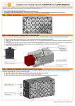
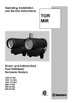
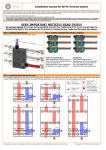
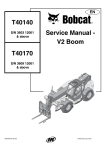
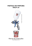
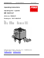
Operating instructions
Operating unit MH 50X70 LP
state of art 09/2011
Operating instructions
Operating Unit - hydralic
MH 50X70 LP
Article no.: 299460-01
Drawing no.: 33.011.068.03-01
For:
2016
2025 / 27
2032 / 36
MIKRO
ALLROUND
ALLROUND
NZ
DNZ / DNZL / NZ
DNZ / DNZL / NZ
Pin Ø 2
Pin Ø 3
Pin Ø 5
PSG Plastic Service GmbH • Pirnaer Str. 12-16 • D 68309 Mannheim
Tel. 0621 71 62 0 • Fax: 0621 71 62 162
[email protected] • www.psg-online.de
Technical changes reserved
Operating instructions
Operating unit MH 50X70LP
state of art 09/2011
TABLE OF CONTENTS
1.. General safety instructions
1.1
1.2
Safety at work
Skilled Experts
2. Important note
2.1
Valve pin operating
2.2
Medium
3. Views + parts list / technical data
3.1
Parts view
3.2
Stock list
3.3
Technical data
4. Pin adjustment by vernier
4.1
Basic setting of the pin (general)
4.2
Final setting ( pin adjustment )
4.3
Uncoupling of the pin gradually
5. Pin removal
6. Sealing change
6.1
Piston sealing (profile ring sealing) installation.
6.2
Piston sealing (profile ring sealing)
PSG Plastic Service GmbH
• Pirnaer Straße 12-16 •
D 68309 Mannheim
Page 2 out of 25
Operating instructions
Operating unit MH 50X70LP
state of art 09/2011
7. 1. General safety instructions
1.1
Safety at work
The tool must be grounded! If the nozzle is operated outside the tool, then the
nozzle must be grounded.
First make sure that the operating unit is ready for use and then start the
heating.
An uncontrolled escape of polymer melt is possible if the hot runner system is
heated up. This could happen if the injection mold is installed as well as if it's
dismantled.
Attention!
Danger of crushing! Don`t reach under the Piston rod.
It’s absolutely necessary to wear protective clothing.
1.2
-
closed protective clothing
-
protective gloves
-
safety helmet
-
protective hood or goggles
-
safety boot
Skilled Experts
Only experts and/or trained persons are authorized to handle hot runner
systems.
PSG Plastic Service GmbH
• Pirnaer Straße 12-16 •
D 68309 Mannheim
Page 3 out of 25
Operating instructions
Operating unit MH 50X70LP
state of art 09/2011
2. Important note
2.1
Valve pin operating
The valve pins can only be operated in heated up condition and with cooling
connected to the operating unit.
Non-observance leads to pin damage. Non-observance leads to pin damage.
2.2
Medium
2.2.1 Hydraulic medium
-
Don’t use flammable hydraulic oil ! Maximum thermal exposure up to 80° C
Consider manufacturer's instructions!
Purity 21/18/13 according to ISO 4406.
Deaerate tubes enough.
Hydraulic fluid on the basis of mineral oil, HLP according to DIN 51524 part 2
(possibly HLVP according to DIN 51524 part 3) with a nominal viscosity of 3246mm²/s. Beyond that enough separation of air and water must be provided.
For the use of additives please consult the supplier for sealings.
2.2.2 Cooling medium water
1. Water quality must be according to VDI guideline 3808.
2. Recommended PH-value 7.0-8.5.
3. Cooling water temperature min 20° C up to max. 60° C (difference
inlet/outlet max. 5° C)
4. Pressure max. 8 bar
5. Minimum flow rate 2 l /min. per unit.
6. Maximum 3 operating units connected in a row
Cooling
Heated up hot runner systems should only be operated with the chiller
connected and running.
In case of non-observance a thermal overloading of the sealing assembly leads
to a leakage or a malfunction of the operating unit.
After turning off heat you can disconnect the chiller.
PSG Plastic Service GmbH
• Pirnaer Straße 12-16 •
D 68309 Mannheim
Page 4 out of 25
Operating unit MH 50X70LP
Operating instructions
state of art 09/2011
3. Views + parts list / technical data
3.1 Parts view
Component parts
sectional view
Figure
1
2 Screw-in fittings G1/8“ for pipe
Ø6 (not part of delivery)
Component parts top
view
Hydraulic oil
Figure
2
water cooling
PSG Plastic Service GmbH
• Pirnaer Straße 12-16 •
D 68309 Mannheim
Page 5 out of 25
Operating unit MH 50X70LP
Operating instructions
state of art 09/2011
3.2 Stock list
Pos.no.
Description
Piece
1
Case
1
2
Holder
1
3
Adjustment lid
1
4
Piston
1
5
Valve pin holder
1
6
Cooling plate
1
7
Spacer
4
8
Locking screw (special part)
1
9
Cooling pipe Ø 6
1
10
Seal assembly
1
11
Thrust spring
4
12
Locking ring
4
13
Allen head screw M5X10 10.9 DIN7984
4
14
Allen head screw M6X75 8.8 DIN6912
4
15
Lock ring DIN 7980
1
16
Cap nut M12 X 1,5
2
17
Compression ring
2
PSG Plastic Service GmbH
Ø6
• Pirnaer Straße 12-16 •
D 68309 Mannheim
Page 6 out of 25
Operating unit MH 50X70LP
Operating instructions
state of art 09/2011
3.3 Technical data
Cylinder
outside dimensions
50 X50 X70 (Height = tool-dimension)
hydraulic pressure
60 bar
hydraulic pipe
Ø 6mm
Pin close
3624 N (piston Ø 28mm)
Pin open
2127 N (Ø 28 – Ø 18 bar)
Stroke
10 mm
oil flow rate
31 ccm/Sec. (0.2 Sec switching time)
swept volume with pin
closed
6.2 ccm
Pin
Ø 2 mm
MIKRO
2016
Ø 3 mm
Allround 2025 / 27 DNZ / DNZL / NZ
Ø 5 mm
Allround 2032 / 36 DNZ / DNZL / NZ
Pin adjustment
+ / - 1mm
Pin - uncoupling
possible
NZ
Cooling (water)
Cooling pipe
Ø 6mm
Flow rate
Min. 2 l / min.
Temperature
20° to 60° C
Consider aftercooling
time
Min. 15 min.
Tightening torques
Pos. 8
Locking screw M6 (special screw)
10 Nm
Pos. 13
Allen head screw M5X10 10.9 DIN7984
6 Nm
Pos. 14
Allen head screw M6X75 8.8 DIN6912
12 Nm
Connections
Cooling pipe
Pipe Ø6 compression ring with cap nut M12X1,5
Hydraulic
G 1/8“
(Reduction GR08/06L for tubing Ø8 not part of delivery)
PSG Plastic Service GmbH
(Screw-in fitting for pipe Ø6 not part of delivery)
• Pirnaer Straße 12-16 •
D 68309 Mannheim
Page 7 out of 25
Operating unit MH 50X70LP
Operating instructions
state of art 09/2011
PSG
4.0 Pin adjustment by vernier
Figure 3
The figure shows the basic setting on delivery.
Each scale division from 0 to 15 is equivalent to 0.1 mm pin adjustment.
With the vernier an adjustment of about 0.01 mm possible.
Clockwise rotation = pin forward
Counterclockwise rotation = pin backward
PSG Plastic Service GmbH
• Pirnaer Straße 12-16 •
D 68309 Mannheim
Page 8 out of 25
Operating unit MH 50X70LP
Operating instructions
state of art 09/2011
4.1 Basic setting of the pin (general)
Clamping screw M5
(pos 13)
Adjustment lid
(pos. 3)
**
Holder
(pos. 2)
*
Case (pos.
1)
Figure
4
-
During the basic setting of the pin
the distance between holder and case is 1 mm
The adjustment lid is located 1 mm deep in the holder.
(adjustment ± 1mm)
-
Caution ! Assemble the operating unit only in basic
setting, otherwise there is a risk for collision in the antechamber.
PSG Plastic Service GmbH
• Pirnaer Straße 12-16 •
D 68309 Mannheim
Page 9 out of 25
Operating instructions
Operating unit MH 50X70LP
state of art 09/2011
4.1.1 Basic setting pin
The basic setting is already made by the factory.
Figure
5
4.1.2
For DNZ and DNZL the pin is already adjusted.
4.1.3
-
Caution ! The basic setting for gate NZ is already made by the factory.
Dimensional deviation could result in a collision between ante-chamber and
pin.
-
Therefore operate the first pin "close" with low pressure and measure the pin
position in the tool section.
-
Adjust the pin position like this, that the phase (X) sticks out of the cavity.
2016 Mikro
Ø
2
2025 / 27 ALLROUND
2032 / 37 ALLROUND
3
5
Min. X
0.05
mm
0.1 mm
0.3 mm
Figure 6
Please consider longer dimensions of the pin in heated up condition. In the
cold condition, the needle must be short by the amount of linear
expansion L
PSG Plastic Service GmbH
• Pirnaer Straße 12-16 •
D 68309 Mannheim
Page 10 out of 25
Operating instructions
Operating unit MH 50X70LP
state of art 09/2011
4.1.4 Basic setting - gradually
Step 1
Change system over to pressure less!
If there is plastic inside, then the system must be heated up.
Step 2
Remove the 4 clamping screw (pos 13).
Step 3
Turn adjustment lid (pos 3) to the same height („tight fit“) as the holder (pos
2).
4 Clamping screw (pos 13).
Adjustment lid (pos 3)
„tight fit“
Holder (pos.
2)
Figure
7
The scale is on the line 10.
Figure
8
PSG Plastic Service GmbH
• Pirnaer Straße 12-16 •
D 68309 Mannheim
Page 11 out of 25
Operating unit MH 50X70LP
Operating instructions
state of art 09/2011
Step 4
Turn adjustment lid in clockwise direction to line 0.
Figure
9
Step 5
Tighten the 4 clamping screws (pos 13) with torque.
Tightening torques
Pos. 13
Allen head screw DIN 7984 M5X10 10.8
6 Nm
Now the operating unit is in basic setting.
4.2. Final setting ( pin adjustment )
For gate type NZ a final setting (pin adjustment) is necessary, because of
molding tolerances.
See point 4.1.3
4.2.1
Systems filled with plastic must be heated up.
PSG Plastic Service GmbH
• Pirnaer Straße 12-16 •
D 68309 Mannheim
Page 12 out of 25
Operating unit MH 50X70LP
Operating instructions
state of art 09/2011
4.2.2. Final setting (pin adjustment) gradually
Please note point 4.1.2 – 4.1.4
Step 1
Change over system to pressure less!
Adjustment lid (pos. 3)
4 Clamping screw (pos 13).
Remove the 4 screws M5X10.
Holder (pos. 2)
Case (pos. 1)
Figure
10
-
For pin adjustment turn off hydraulic pressure.
-
Systems filled with plastic must be heated up.
-
Unscrew the 4 clamping screws (pos 13) M5X10
about 1mm.
Attention!
Danger of crushing! Don`t reach under the Piston rod.
PSG Plastic Service GmbH
• Pirnaer Straße 12-16 •
D 68309 Mannheim
Page 13 out of 25
Operating unit MH 50X70LP
Operating instructions
state of art 09/2011
4.2.2. Final setting (pin adjustment) gradually
Step 2
Screw the adjustment lid (pos. 3) 0.5
mm forward.
Holder (pos. 2)
Case (pos. 1)
Figure 11
-
Turn the lid in clockwise direction to move the pin
forward, turn the lid in counterclockwise direction
to move the pin back, according to vernier.
-
The adjustment (pos. 3) lid was screwed forward
about 0.5 mm.
-
The case (pos. 1) with cooling plate (pos. 6)
moved forward about 0.5 mm by the fixed holder
(pos. 2) .
-
The distances change up to 1.5 mm.
-
The piston stroke is minimally 10 mm.
PSG Plastic Service GmbH
• Pirnaer Straße 12-16 •
D 68309 Mannheim
Page 14 out of 25
Operating unit MH 50X70LP
Operating instructions
state of art 09/2011
4.2.2. Final setting (pin adjustment) gradually
Step 3
4 Clamping screw (pos 13).
Tighten the 4 screws M5X10
(pos.13). (6 Nm)
Adjustment lid (pos. 3)
Holder (pos. 2)
Case (pos. 1)
Figure
12
-
Then retighten the 4 screws M5x10 (pos. 13).
Tightening torques
Pos. 13
Allen head screw DIN 7984 M5X10 10.9
-
The position is adjusted and locked.
-
Connect hydraulic pressure
PSG Plastic Service GmbH
• Pirnaer Straße 12-16 •
D 68309 Mannheim
6 Nm
Page 15 out of 25
Operating unit MH 50X70LP
Operating instructions
state of art 09/2011
4.3. Uncoupling of the pin gradually
Step 1
Change over system to pressure less!
pos. 15
pos. 14
Figure
13
-
To uncouple the pin remove the following screws:
4 pcs. M5 X 10 (pos 14)
4 pcs. M6 X 75 (pos 15)
entfernt.
PSG Plastic Service GmbH
• Pirnaer Straße 12-16 •
D 68309 Mannheim
Page 16 out of 25
Operating instructions
Operating unit MH 50X70LP
state of art 09/2011
4.3 Uncoupling of the pin
Step 2
Adjustment lid (pos. 3)
Holder (pos. 2)
Figure
14
-
Mark the position of the adjustment lid (pos. 3) in the holder (pos. 2) (vernier).
-
Draw the holder (pos. 2) upwards together with the adjustment lid (pos. 3).
PSG Plastic Service GmbH
• Pirnaer Straße 12-16 •
D 68309 Mannheim
Page 17 out of 25
Operating unit MH 50X70LP
Operating instructions
state of art 09/2011
4.3 Uncoupling of the pin
Step 3
Loosen locking screw M5 (pos. 8).
Consider
Draw the case
(pos. 1) upward
Hold against
with allen
wrench key
Piston (pos. 4)
Sealing of the locking
screw (pos. 8).
Pin holder (pos. 5)
Figure
15
-
Remove the screw (pos. 8) in the piston (pos. 4) and loosen the
pin holder (pos. 5). (Piston (pos. 4) hold against with allen
wrench key).
-
To avoid the escape of hydraulic oil pull the case (pos. 1)
upwards if you remove the locking screw (pos. 8).
Thus the sealing of the locking screw (pos. 8) is still guaranteed.
PSG Plastic Service GmbH
• Pirnaer Straße 12-16 •
D 68309 Mannheim
Page 18 out of 25
Operating instructions
Operating unit MH 50X70LP
state of art 09/2011
4.3 Uncoupling of the pin
Step 4
Push pin holder (pos. 5)
sideward.
Figure
16
-
Now push the pin holder (pos. 5) sideways off the pin.
PSG Plastic Service GmbH
• Pirnaer Straße 12-16 •
D 68309 Mannheim
Page 19 out of 25
Operating instructions
Operating unit MH 50X70LP
state of art 09/2011
5. Pin removal
To withdraw the pin, first must be uncoupling the Pin.
See Point 4.3
Withdraw pin off nozzle head with
nipper or with suitable pin take-off aid.
Attention !
If it is plastic in the Manifold and in the nozzle, tey must be heat up to melting
temperature.
PSG Plastic Service GmbH
• Pirnaer Straße 12-16 •
D 68309 Mannheim
Page 20 out of 25
Operating unit MH 50X70LP
Operating instructions
state of art 09/2011
6. Sealing change
6.1. Piston sealing (profile ring sealing) installation.
Step 1
-
Insert the O-ring in the piston groove, then push the profile ring sealing over
the calibrating mandrel by the use of a calibrating ring.
-
Thus the profile ring-sealing is stretched and pushed into the piston groove.
Calibrating
ring
Calibrating
mandrel
Profile ring sealing
Piston
O-ring
Lubricate the sliding surface
Figure
17
The calibrating tool can be ordered by PSG.
PSG Plastic Service GmbH
• Pirnaer Straße 12-16 •
D 68309 Mannheim
Page 21 out of 25
Operating instructions
Operating unit MH 50X70LP
state of art 09/2011
6.2. Piston sealing (profile ring sealing)
Step 2
Turn the calibrating ring and push it at the conical side over the profile ring
sealing to unstretch the sealing. (First remove the calibrating mandrel)
Calibrating
ring
Profile ring sealing
Figure
18
conical side
PSG Plastic Service GmbH
• Pirnaer Straße 12-16 •
D 68309 Mannheim
Page 22 out of 25
Operating instructions
Operating unit MH 50X70LP
state of art 09/2011
Graphed are the important parts of the calibrating tool.
Calibrating
ring
Calibrating
mandrel
polished
„Z“
Figure
19
Section „Z“
PSG Plastic Service GmbH
• Pirnaer Straße 12-16 •
D 68309 Mannheim
Page 23 out of 25
Operating instructions
Operating unit MH 50X70LP
state of art 09/2011
5.3 Lip seals
Lubricate the lip seal (piston rod seal). Squeeze carefully with your fingers to
warm and soften the lip seal.
Shape like this
Bild 20
Lip seal
Take between fingers or nipper.
Carefully: don't bend!
Then press the sealing carefully into the
appropriated groove in the cylinder
case.
Figure
21
(Cylinder case seen from above)
PSG Plastic Service GmbH
• Pirnaer Straße 12-16 •
D 68309 Mannheim
Page 24 out of 25
Operating instructions
-
Operating unit MH 50X70LP
state of art 09/2011
Caution ! Consider, that the lip seals point in the right direction.
Figure
22
-
Beat carefully against the seal with a wood
or a brass small tube.
Figure
23
PSG Plastic Service GmbH
• Pirnaer Straße 12-16 •
D 68309 Mannheim
Page 25 out of 25