1
AlliedView™-UM 2.0
USER’S GUIDE
AlliedView™-UM 2.0 USER’S GUIDE
Page 1 of 128
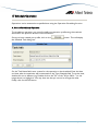
TABLE OF CONTENTS
1 INTRODUCTION ............................................................................................................................................. 5
2 A GUIDED TOUR ............................................................................................................................................. 6
A. LAUNCHING THE APPLICATION ........................................................................................................................ 6
B. CREATING A DEVICE ........................................................................................................................................ 7
C. UPGRADING SOFTWARE ................................................................................................................................ 11
D. THE ALLIEDVIEW-UM SYSTEM FOLDERS ......................................................................................................... 12
3 MAIN WINDOW ............................................................................................................................................ 13
A. DEVICE FAMILIES PANE ................................................................................................................................... 14
B. OPERATIONS SELECTION PANE ....................................................................................................................... 15
C. OPERATIONS PANE........................................................................................................................................ 16
D. OPERATION LOGS PANE................................................................................................................................ 16
4 DEVICE GROUPS ............................................................................................................................................ 17
A. CREATING A DEVICE GROUP ......................................................................................................................... 17
B. DELETING A DEVICE GROUP........................................................................................................................... 18
C. RENAMING A DEVICE GROUP......................................................................................................................... 19
D. LOADING DEVICE GROUPS ............................................................................................................................ 20
E. CLOSING DEVICE GROUPS.............................................................................................................................. 21
5 DEVICE DEFINITIONS .................................................................................................................................... 24
A. CREATING A DEVICE DEFINITION ................................................................................................................... 24
B. LOADING/UPDATING DEVICE DEFINITIONS FROM A COMMA SEPARATED VALUE (CSV) FILE ............................. 28
C. DISCOVERING NEW DEVICES ......................................................................................................................... 31
D. VIEWING DEVICE DEFINITIONS ...................................................................................................................... 36
E. MODIFYING DEVICE DEFINITIONS ................................................................................................................... 39
F. DELETING DEVICE DEFINITIONS ...................................................................................................................... 40
6 LICENSE LIST FILES ......................................................................................................................................... 42
A. GENERATING LICENSE REQUEST FILES.................................................................................................. 42
B. GENERATING LICENSE LIST FILES ........................................................................................................... 44
C. LICENSE LIST FILE FOR RELEASE UPGRADE (ALLIEDWARE) OPERATIONS........................................................... 50
D. LICENSE LIST FILE FOR ENABLE FEATURES OPERATIONS ................................................................................... 51
7 RELEASE UPGRADE OPERATION................................................................................................................. 52
A. CREATING A RELEASE UPGRADE PROFILE ........................................................................................................ 54
B. SAVING A RELEASE UPGRADE PROFILE ............................................................................................................. 58
C. LOADING A RELEASE UPGRADE PROFILE ......................................................................................................... 58
D. STARTING THE RELEASE UPGRADE OPERATION .............................................................................................. 60
8 INTERIM/MAINTENANCE RELEASE UPGRADE OPERATION.................................................................... 62
A. CREATING AN INTERIM/ MAINTENANCE RELEASE UPGRADE PROFILE................................................................ 63
B. SAVING AN INTERIM/MAINTENANCE RELEASE UPGRADE PROFILE ..................................................................... 64
C. LOADING AN INTERIM/MAINTENANCE RELEASE UPGRADE PROFILE.................................................................. 65
D. STARTING THE INTERIM/MAINTENANCE RELEASE UPGRADE OPERATION ......................................................... 66
9 PATCH UPGRADE OPERATION................................................................................................................... 68
A. CREATING A PATCH UPGRADE PROFILE.......................................................................................................... 69
B. SAVING A PATCH UPGRADE PROFILE .............................................................................................................. 70
C. LOADING A PATCH UPGRADE PROFILE ........................................................................................................... 71
D. STARTING THE PATCH UPGRADE OPERATION ................................................................................................ 72
AlliedView™-UM 2.0 USER’S GUIDE
Page 2 of 128
10 CONFIGURATION FILE UPDATE ............................................................................................................... 74
A. CREATING A CONFIGURATION FILE UPDATE PROFILE ..................................................................................... 75
B. SAVING A CONGFIGURATION FILE UPDATE PROFILE ....................................................................................... 77
C. LOADING A CONFIGURATION FILE UPDATE PROFILE ...................................................................................... 77
D. STARTING THE CONFIGURATION FILE UPDATE OPERATION............................................................................ 79
11 EXECUTE SCRIPT FILE.................................................................................................................................. 81
A. CREATING A EXECUTE SCRIPT FILE PROFILE .................................................................................................... 81
B. SAVING AN EXECUTE SCRIPT FILE PROFILE....................................................................................................... 83
C. LOADING AN EXECUTE SCRIPT FILE PROFILE ................................................................................................... 83
D. STARTING THE EXECUTE SCRIPT FILE OPERATION .......................................................................................... 85
12 GUI RESOURCE FILE UPDATE..................................................................................................................... 87
A. CREATING A GUI RESOURCE FILE UPDATE PROFILE ........................................................................................ 88
B. SAVING A GUI RESOURCE FILE UPDATE PROFILE ............................................................................................. 89
C. LOADING A GUI RESOURCE FILE UPDATE PROFILE ......................................................................................... 90
D. STARTING THE GUI RESOURCE FILE UPDATE OPERATION .............................................................................. 91
13 HELP FILE UPDATE ....................................................................................................................................... 93
A. CREATING A HELP FILE UPDATE PROFILE ........................................................................................................ 94
B. SAVING A HELP FILE UPDATE PROFILE ............................................................................................................. 95
C. LOADING A HELP FILE UPDATE PROFILE ......................................................................................................... 96
D. STARTING THE HELP FILE UPDATE OPERATION............................................................................................... 97
14 ENABLE FEATURE OPERATIONS................................................................................................................ 99
A. CREATING AN ENABLE FEATURES PROFILE ...................................................................................................... 99
B. SAVING AN ENABLE FEATURE PROFILE ........................................................................................................... 100
C. LOADING AN ENABLE FEATURES PROFILE ..................................................................................................... 101
D. STARTING THE ENABLE FEATURES OPERATION ............................................................................................. 102
15 REBOOT DEVICE ........................................................................................................................................ 104
A. CREATING A REBOOT DEVICE PROFILE ......................................................................................................... 104
B. SAVING A REBOOT DEVICE PROFILE .............................................................................................................. 104
C. LOADING A REBOOT DEVICE PROFILE .......................................................................................................... 105
D. STARTING THE REBOOT DEVICE OPERATION ............................................................................................... 106
16 AUDIT TRAIL............................................................................................................................................... 108
A. VIEWING THE AUDIT TRAIL .......................................................................................................................... 108
17 SCHEDULE OPERATION ........................................................................................................................... 110
A. HOW TO SCHEDULE AN OPERATION ........................................................................................................... 110
B. VIEWING TASKS ........................................................................................................................................... 111
C. EDITING TASKS ........................................................................................................................................... 112
D. ABORTING A TASK ...................................................................................................................................... 113
E. DELETING A TASK ........................................................................................................................................ 115
18 ROLLBACK .................................................................................................................................................. 116
A. ROLLBACKS AND THE AUDIT TRAIL .............................................................................................................. 116
B. SPECIAL RULES ON ROLLBACKS .................................................................................................................... 117
C. PERFORMING A ROLLBACK ON A DEVICE...................................................................................................... 117
D. PERFORMING A ROLLBACK ON AN OPERATION PROFILE ............................................................................... 119
AlliedView™-UM 2.0 USER’S GUIDE
Page 3 of 128
19 LICENSE REGISTRATION........................................................................................................................... 122
A. REGISTERING A LICENSE ............................................................................................................................... 122
B. MODIFYING A LICENSE ................................................................................................................................. 124
20 OPTIONS ..................................................................................................................................................... 126
A. VIEW SETTINGS ........................................................................................................................................... 126
B. THREAD SETTINGS ....................................................................................................................................... 127
AlliedView™-UM 2.0 USER’S GUIDE
Page 4 of 128
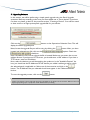
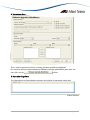
1 Introduction
AlliedView-UM is a Java-based application that allows fast and efficient distribution of
Software Upgrades, Patches, GUI Resource files, Help, Configuration files and Script files
on Allied Telesis network devices. It provides a batch method of downloading software or
a file onto devices via TFTP or HTTP. It also provides the ability to enable the downloaded
software or file and enable features on multiple devices.
RECOMMENDED READING
AlliedView-UM basically builds upon the CLI commands of Allied Telesis management
software. Refer to the Software Reference Manual or CLI User’s Guide that accompanies
every AT network device for a better understanding of these commands.
OTHER REQUIREMENTS
The user should have some background in network device management specifically for
AT network devices.
1 Introduction
AlliedView™-UM 2.0 USER’S GUIDE
Page 5 of 128
2 A Guided Tour
This section introduces all the basic features of AlliedView-UM. This section is not intended
to be a reference and will thus not explain all the details.
A. Launching the Application
To begin the tour, start the application using any of the following methods:
For Windows systems:
•
•
•
Double-click on the executable file "um.exe" or its corresponding shortcut through
Windows Explorer.
Enter the installation path specified during installation followed by "\bin\um.exe" on
the command line
Click on the application icon in the AlliedView-UM program group
For Solaris and HP-UX systems:
•
Move to the directory where AlliedView-UM was installed, and type "./bin/um" on
the command line.
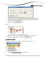
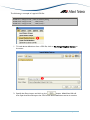
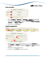
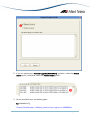
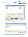
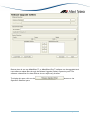
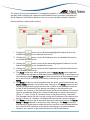
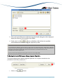
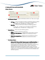
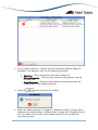
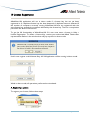
The image below illustrates the initial screen display of AlliedView-UM.
AlliedView™-UM 2.0 USER’S GUIDE
Page 6 of 128
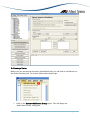
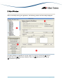
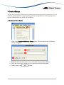
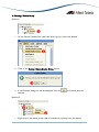
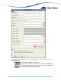
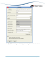
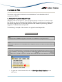
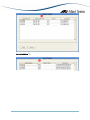
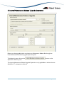
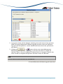
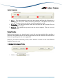
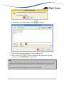
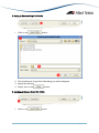
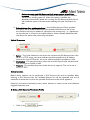
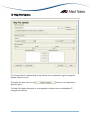
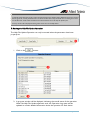
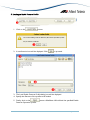
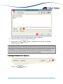
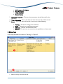
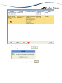
B. Creating a Device
Before you can use the main functions of AlliedView-UM, you will need to add Devices on
the Device Families pane. To do that, follow these simple steps.
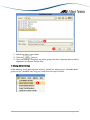
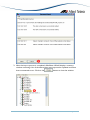
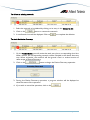
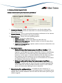
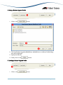
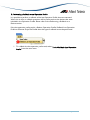
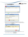
1. Click on the Device->Add Device Group option. This will display the
“Add Device Group” dialog box.
AlliedView™-UM 2.0 USER’S GUIDE
Page 7 of 128
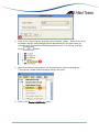
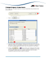
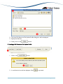
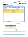
2. Click on the “Device Family” dropdown list and select “Rapier”. If you do not have
any Rapier devices, select the appropriate device family for the device that you
currently have. On the Device Group Name field, input “Test Group” and click
on the
button.
3. Look at the Device Families pane. You should see your newly created group
("Test Group") added under the Rapier Family root node.
4. Click on the Device->Add Device option.
AlliedView™-UM 2.0 USER’S GUIDE
Page 8 of 128
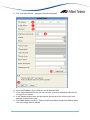
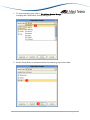
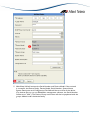
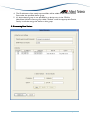
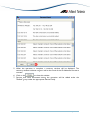
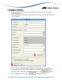
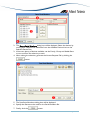
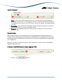
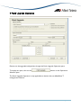
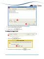
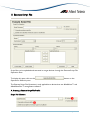
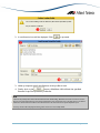
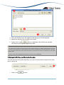
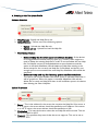
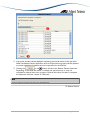
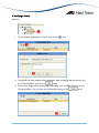
5. The “Add New Device” dialog box should be displayed.
6. Input the IP address of your device in the IP Address field.
7. In the Login Name field, enter the user account name that AlliedView-UM will use
to login to your device.
8. In the Password field, enter the appropriate password for the account you have
entered in the previous step.
9. The SNMP Read Community, Timeout and Retries fields already have default values.
You may change these if needed.
AlliedView™-UM 2.0 USER’S GUIDE
Page 9 of 128
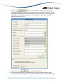
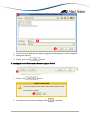
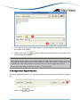
10. Click on the
button. If the IP Address, Login Name, Password,
and SNMP Read Community that you specified are correct, then the Device Family,
Device Model, Serial Number, System Name, System Description and Configuration
File fields should now be set. If an error occurs, please re-check the values you
entered in steps (6) to (9).
11. Finally, click on the
button to add the device.
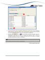
12. Your new device should now be added. If you check the Device Families pane,
you should see the IP Address of your device under the group called, "Test Group".
AlliedView™-UM 2.0 USER’S GUIDE
Page 10 of 128
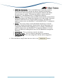
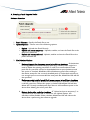
C. Upgrading Software
In this section, we will be performing a simple patch upgrade using the Patch Upgrade
operation. Before proceeding, make sure you have added one or more devices. If you have
not done so, please go back to the previous section, "Creating a Device". You will also need
to have access to an appropriate patch upgrade file for your device.
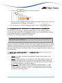
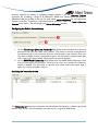
Click on the
display the Patch Upgrade pane.
button on the Operations Selection Pane. This will
Next, locate the upgrade file you will be using by clicking the
button. After you have
located and selected your file, click on the
option. Check the
checkbox.
Enter the address of the server where the file is located. Make sure you enter the correct
address format. If you have an HTTP server, you should enter a URL address. If you have a
TFTP server, enter an IP Address.
Now, select the devices you will be applying the update to. In the "Available Devices" list
box, you should see the IP Addresses of the devices you added a while ago and for which
the selected patch is applicable to. Select one of those entries and click on the
button. The IP Address that you selected should now appear in the "Selected Devices"
list box.
To start the upgrade process, click on the
button.
NOTE:
Upgrading and rebooting a device will make that device unavailable for the duration of the operation. Make sure that you
notify the appropriate groups or people that will be affected before proceeding.
AlliedView™-UM 2.0 USER’S GUIDE
Page 11 of 128
D. The AlliedView-UM System Folders
Deleting or modifying any of the files under the AlliedView-UM installation folder is not
recommended. Doing so will cause the application to function incorrectly.
2 A Guided Tour
AlliedView™-UM 2.0 USER’S GUIDE
Page 12 of 128
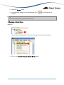
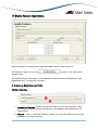
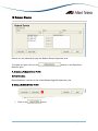
3 Main Window
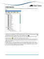
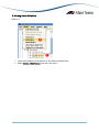
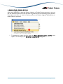
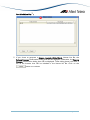
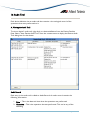
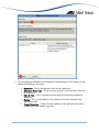
After successfully starting the application, the following window will be initially displayed:
The Main Window is divided into 4 major panes (or regions), namely the (1) Device
Families Pane, the (2) Operations Selection Pane, the (3) Operations Pane and the
(4) Operation Logs Pane.
AlliedView™-UM 2.0 USER’S GUIDE
Page 13 of 128
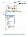
A. Device Families Pane
The Device Families Pane is used to manage the devices that AlliedView-UM can interface
with.
The root nodes of the Device Families represent the AT Device Families that are currently
supported by this application. The AT Device Firmware root node is represented by a ( )
icon followed by the AT Device Family name represented by a ( ).
Each AT Device Family node can contain Device Group nodes. A Device Group node is
represented by a ( ) icon followed by the Device Group name.
Finally, a Device Group node can contain Device nodes. A Device node is represented by
a ( ) icon followed by the IP address of that device. A Device node cannot contain any
other nodes under it.
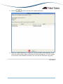
Double clicking on a node will display the corresponding dialog box that will allow you
to perform functions pertaining to that node. For instance, if you double click on a Device
Node, the Edit Device dialog box will be displayed. From the Edit Device dialog box you
can view and modify some of the device attributes.
AlliedView™-UM 2.0 USER’S GUIDE
Page 14 of 128
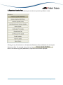
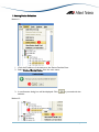
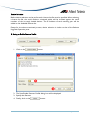
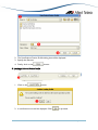
B. Operations Selection Pane
The Operations Selection Pane allows you to select an operation profile to create.
Clicking on any of the buttons in the Operation Selections Pane will display the appropriate
Operations Pane. For example, if you click on the
button, the Release Upgrade (AlliedWare) Operations Pane will be displayed.
AlliedView™-UM 2.0 USER’S GUIDE
Page 15 of 128
C. Operations Pane
This is where operation panes for creating operation profiles are displayed.
For instance, the figure above displays the Release Upgrade (AlliedWare) pane after the
user clicks on the
button.
D. Operation Logs Pane
The Operation Logs Pane displays the status and results of operations performed.
3 Main Window
AlliedView™-UM 2.0 USER’S GUIDE
Page 16 of 128
4 Device Groups
A device group represents a logical grouping used to manage devices. A device group must
first be created before any device can be defined.
A. Creating a Device Group
1. Click on the Device->Add Device Group option. This will display the “Add Device
Group” dialog box.
2. Select the Device Family where your new Device Group will be added to.
3. Enter the name of your device group in the Device Group Name field.
4. Finally, click on the
AlliedView™-UM 2.0 USER’S GUIDE
button.
Page 17 of 128
B. Deleting a Device Group
Method 1:
1. On the Device Families Pane, select the device group node to be deleted.
2. Click on the Device->Delete Device Group option.
3. A confirmation dialog box will be displayed. Click on
deletion.
to proceed with the
Method 2:
1. Right click on the device group node to be deleted. A popup menu will appear.
AlliedView™-UM 2.0 USER’S GUIDE
Page 18 of 128
2. Select the Delete option.
3. A confirmation dialog box will be displayed. Click
deletion.
to proceed with the
NOTE:
Any device under the deleted device group will be deleted as well.
C. Renaming a Device Group
Method 1:
1. On the Device Families Pane, select the device group node to be renamed.
2. Click on the Device->Rename Device Group option.
AlliedView™-UM 2.0 USER’S GUIDE
Page 19 of 128
3. The Rename Device Group dialog box will be displayed. The Device Group Name
field contains the currently assigned name for that device group. Type in the new
name in the Device Group Name field.
4. Finally, click on the
button.
Method 2:
1. Right click on the Device Group node to be renamed.
2. Select the “Rename” option to display the Rename Device Group dialog box.
3. Rename the device group. Then click on the
button.
D. Loading Device Groups
Device groups which have been closed can be reloaded using this function.
1. Click on File->Load Device Groups on the main menu.
AlliedView™-UM 2.0 USER’S GUIDE
Page 20 of 128
2. Specify the file(s) to be loaded.
3. Click the
button.
4. Once the loading is complete, the device groups with their respective devices will be
displayed in the Device Families Pane
E. Closing Device Groups
Unlike deleting, closing device groups will only "unload" the device groups. Unloaded device
groups can be "reloaded" later using the "Load Device Groups" function.
AlliedView™-UM 2.0 USER’S GUIDE
Page 21 of 128
1. To close a device group, click on File->Close Device Groups on the main menu
to display the Close Device Groups dialog box.
2. Set the Family Filter to the device family of the device group to be closed.
AlliedView™-UM 2.0 USER’S GUIDE
Page 22 of 128
3. Select the device group to close.
4. Finally, click on the
button.
4 Device Group
AlliedView™-UM 2.0 USER’S GUIDE
Page 23 of 128
5 Device Definitions
Devices must first be defined before they can be included in any operation.
Also, TELNET LOGIN support for a device must be enabled in order for AlliedView-UM
to interface with it.
A. Creating a Device Definition
1. Before you add any new devices, make sure you have already defined a Device
Group. If you have not done so, please create one using the steps described in the
previous section, Creating a Device Group.
2. Click on the Device->Add Device option.
AlliedView™-UM 2.0 USER’S GUIDE
Page 24 of 128
3. The Add New Device dialog box will be displayed with the input fields blank or set
to a default value:
• IP Address - This is the IP Address of the device.
• Login Name - This is the user account recognized by the device. AlliedView-UM
will login to the device using this account to perform the different operations.
• Password - This is the password for the login name.
AlliedView™-UM 2.0 USER’S GUIDE
Page 25 of 128
•
•
•
•
•
•
SNMP Read Community - This is the SNMP Read Community name that
AlliedView-UM will use to retrieve the device’s Model, Serial Number,
System Name, Device Description and Configuration filename. By default,
this value is set to “public”. (This field only applies to devices that use
AlliedWare™ and AlliedWare Plus™ management software.)
Timeout - When retrieving the device’s Model, Serial Number, System Name,
Device Description and Configuration filename, this is the number of seconds
AlliedView-UM will wait for a response before retrying. (This field only
applies to devices that use AlliedWare™ and AlliedWare Plus™ management
software.)
Retries - This is the number of times AlliedView-UM will try to retrieve
the device’s Model, Serial Number, System Name, Device Description and
Configuration filename before displaying an error message. (This field only
applies to devices that use AlliedWare™ management software. You may
ignore this field when adding devices that use non-AlliedWare management
software.)
System Name - This is an arbitrary name for the device.
System Description - This is an arbitrary description for the device.
Configuration File - This is the configuration file that will be assigned for
this device.
4. Once the fields in step (3) have been set, click on the
AlliedView™-UM 2.0 USER’S GUIDE
button.
Page 26 of 128
5. AlliedView-UM will retrieve the Serial Number and Device Model. If the retrieval
is successful, the Device Family, Device Model, Serial Number, System Name,
System Description and Configuration File fields will be set to that of the device.
(For devices that run on non-AlliedWare management software, the Serial Number
will be set to "N/A".) The Device Group combo box will also be populated with the
groups defined under the device family.
AlliedView™-UM 2.0 USER’S GUIDE
Page 27 of 128
6. Click on the
button to add the new device.
7. After the device is added, the Device Families Pane will be updated with a new node
represented by the IP address of that device.
8. If you decide not to continue adding the device, click on the
button.
B. Loading/Updating Device Definitions from a Comma Separated Value (CSV) File
An alternative way of adding or updating multiple devices is by pre-defining them in a
Comma Separated Value (CSV) file. AlliedView-UM then imports the definitions contained
in this file and adds them to the specified device group.
The format of a CSV device definition is as follows:
IP_Address, login_name, password, system_name, system_description, SNMP_read_community, SNMP_timeout,
SNMP_retry, device_group, configuration_file
During the operation, AlliedView-UM will check if the IP_Address field of an entry is already
defined in the Device Family Tree. If the entry is already defined, then AlliedView-UM will
update the existing device definition with the values from the CSV file entry. Otherwise,
if the entry does not exist in the Device Family Tree, then AlliedView-UM will create a new
Device Definition.
The system_name, system_description and configuration_file fields may be set to the
following values:
•
•
•
<value> - If a value is provided, then AlliedView-UM will use that value for the
device definition.
<blank> - When importing a device definition, if the field is blank (no value), then
AlliedView-UM will retrieve the value from the target device. When updating an
existing device definition, if the field is blank, then AlliedView-UM will not update
the corresponding field in the device definition.
"*" (asterisk) - When updating a device definition, if the field is set to "*", then
AlliedView-UM will retrieve the value from the target device. When importing
a device defintion, if this field is set to "*", then AlliedView-UM will also retrieve
the value from the target device.
AlliedView™-UM 2.0 USER’S GUIDE
Page 28 of 128
The following is a sample of a typical CSV file:
192.168.10.9, manager, friend, Main, Used QA Group,public,10,3,Security,tomato.cfg
192.168.10.11, manager, friend, , ,public,10,3,Security,lab.cfg
192.168.10.30, manager, friend, , , , , , 8400_Group,
192.168.10.31, manager, friend, , , , , , 8400_Group,*
1. To load device definitions from a CSV file, click on File->Import/Update Devices on
the menu.
2. Specify the file to import and click on the
button. AlliedView-UM will
then open that file and import the CSV format device definition entries it contains.
AlliedView™-UM 2.0 USER’S GUIDE
Page 29 of 128
3. After the import process is completed, AlliedView-UM will display a summary
window containing a list of the devices that were imported or updated and those
that encountered errors. Click on the
AlliedView™-UM 2.0 USER’S GUIDE
button to close the window.
Page 30 of 128
4. The IP addresses of the newly imported files will be added to the Device Families
Pane under the specified device group.
5. If a device device group is not specified for a device entry in the CSV file,
AlliedView-UM will create a group called, "Default" under the appropriate Device
Family. It will then assign the device to that group.
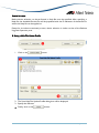
C. Discovering New Devices
AlliedView™-UM 2.0 USER’S GUIDE
Page 31 of 128
Another method for adding or updating multiple devices is via the Discover Devices
operation. By providing a range of IP addresses, SNMP and Telnet access parameters,
AlliedView-UM will be able to do scan for and create device definitions for any supported
devices it may find. To perform a Discover Devices operation, select the Tools > Discover
Devices menu option. This will display the Device Discovery window.
Configuring the Default Access Settings
1. On the Telnet Login (Account, Password) field, please enter the telnet accounts and
passwords that you use within your network. The format is account_name,password
(ex. admin,secret). If you use more than one account within your network, then you
may enter multiple account_name,password pairs. You will need to separate each pair
with a space. (ex. admin,secret, master,password, doctor,docpass)
2. On the SNMP Read Community field, please enter the SNMP Read community name
that you use within your network. You may enter more any number of community
names if needed. You will need to separate each Read community name with a
space. (ex. secret, armadillo, arabica)
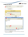
Specifying the Networks to Scan
The Networks list indicate the networks that AlliedView-UM will scan to detect supported
devices. Each entry in this list indicates one network (or range of IP Addresses).
AlliedView™-UM 2.0 USER’S GUIDE
Page 32 of 128
To add a new network:
1. Enter an IP Address and Netmask in the IP Address and Netmask fields respectively.
2. If you wish to specify a specific range within the IP Address/Netmask pair you've just
entered, select the Set of nodes option. You may then enter a Starting and/or Ending
IP Address on the Start IP and End IP fields.
3. Finally, click on the
button.
To modify an existing network:
1. Select the network to be modified by clicking on its entry in the Networks list
2. The IP Address and Netmask fields will be populated by the values of the selected
network. If a set of nodes are specified, the Start IP and End IP will also be
populated.
3. You may now modify the existing values.
4. Finally, click on the
AlliedView™-UM 2.0 USER’S GUIDE
to reflect the changes.
Page 33 of 128
To delete an existing network:
1. Select the network to be deleted by clicking on its entry in the Networks list.
2. Click on the
button to remove the network.
3. A confirmation box will be displayed. Click on
to complete the deletion.
To start the device discovery:
1. On the Networks list, you will notice that each entry has a corresponding check box.
When checked, the corresponding network will be included in the device discovery
scan. When unchecked, the network will be ignored. Check or uncheck entries to
refine scope of Device Discovery.
2. Click on the
button to begin the Device Discovery operation.
3. During the Device Discovery operation, a progress window will be displayed to
show the status of the operation.
4. If you wish to cancel the operation, click on the
AlliedView™-UM 2.0 USER’S GUIDE
.
Page 34 of 128
5. When the operation is complete, a summary window will be displayed. The
summary window indicates range as well as the result of the IP Addresses that were
scanned.
to close this window.
6. Click on the
7. Devices that were discovered during the operation will be added under the
"Default" group under the appropriate Device Family.
AlliedView™-UM 2.0 USER’S GUIDE
Page 35 of 128
D. Viewing Device Definitions
Method 1:
1. Click the IP address of the device on the Device Families Pane.
2. Select Device->Edit Device from the main menu.
AlliedView™-UM 2.0 USER’S GUIDE
Page 36 of 128
3. The Edit Device dialog box will be displayed containing information for the selected
device.
AlliedView™-UM 2.0 USER’S GUIDE
Page 37 of 128
Method 2:
1. Right click on the IP address of the device on the Device Families Pane.
2. Select edit from the popup menu.
3. The Edit Device dialog box will be displayed containing information for the selected
device.
Method 3:
1. Double-click the IP address of a device on the Device Families Pane.
2. The Edit Device dialog box will be displayed containing information for the selected
device.
AlliedView™-UM 2.0 USER’S GUIDE
Page 38 of 128
E. Modifying Device Definitions
1. Display the Device Definition to be modified. (See the previous section, Viewing
Device Definitions)
2. Once the Edit Device dialog box is displayed, the information for the selected device
can be modified.
3. If you modify the IP Address field, it is highly recommended that you refresh the
values of the Device Family, Device Model, Serial Number, System Name, System
Description and Configuration File fields by clicking on the
4. After modifying the values, click on
AlliedView™-UM 2.0 USER’S GUIDE
button.
to apply the changes.
Page 39 of 128
F. Deleting Device Definitions
Method 1:
1. Click the IP address of the device on the Device Families Pane.
2. Select Device->Delete Device from the main menu.
3. A confirmation dialog box will be displayed. Click
deletion.
to proceed with the
Method 2:
AlliedView™-UM 2.0 USER’S GUIDE
Page 40 of 128
1. Right click on the IP address of the device on the Device Families Pane.
2. Select Delete from the popup menu.
3. Click
on the confirmation dialog box to proceed with the deletion.
NOTE:
AlliedView-UM does not support AT-8000S devices that are configured or setup to be in stacked mode.
5 Device Definitions
AlliedView™-UM 2.0 USER’S GUIDE
Page 41 of 128
6 License List Files
This section only applies to devices that use AlliedWare™ and AlliedWare Plus™
management software.
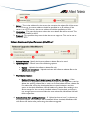
A. GENERATING LICENSE REQUEST FILES
AlliedView-UM has the option to export the Serial Number of devices to a serial number
file. The file can then be uploaded onto WebGen. WebGen reads the serial numbers from
the file and generates the corresponding license list file needed for performing a Release
Upgrade or an Enable Features operation.
The following is a sample of the contents of a typical License Request file:
123045434568932178916768
NOTE:
License Request Files via WEBGEN only applies to devices that run on AlliedWare™ management software.
NOTE:
Feature licenses of devices that run on AlliedWare Plus™ management software are acquired from Allied Telesis sales
representative.
NOTE:
As of this time, the WebGen interface for accepting the serial number file from AlliedView-UM to generate a license list
file is not yet available. For the time being, you would need to manually supply WebGen with the device serial numbers to
generate
the
required
passwords.
You would then have to manually create the corresponding license list file using the formats discussed in the succeeding
sections.
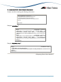
1. To generate a Serial Number file, click on File->Export Serial Numbers on the
main menu.
AlliedView™-UM 2.0 USER’S GUIDE
Page 42 of 128
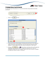
2. The Export Serial Numbers dialog box will be displayed. Select the devices by
moving their respective IP addresses from the Available Devices list into the
Selected Devices list.
3. If there are plenty of devices available, use the Family, Group and Model filters
to narrow down the selection process.
4. After making the selection, generate the License Request File by clicking the
button.
5. The Save Serial Numbers dialog box will be displayed.
6. Specify the filename to be used for the Serial Numbers file.
7. Finally, click the
AlliedView™-UM 2.0 USER’S GUIDE
button.
Page 43 of 128
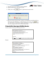
B. GENERATING LICENSE LIST FILES
After using WEBGEN to generate Release Upgrade or Enable Features passwords, you can
use the Generate License List File operation to generate the corresponding license list files.
These license list files can then be used to perform the Release Upgrade (AlliedWare) or
Enable Features operation.
1. To generate a License List file, select the File > Generate License List File menu
option. This will display the Generate License List File dialog box.
AlliedView™-UM 2.0 USER’S GUIDE
Page 44 of 128
2. If you are performing a Release Upgrade (AlliedWare) operation, select the Release
License option. Otherwise, select the Feature License option.
3. On the text field, enter the following data:
For AlliedWare™:
<Device Serial Number> <Enabling Command (as it appears in WEBGEN)>
AlliedView™-UM 2.0 USER’S GUIDE
Page 45 of 128
You must have one entry for each device you wish to include in the License List file.
Note that you may not mix Release Upgrade (AlliedWare) and Enable Features
entries.
Example:
Release Upgrade (AlliedWare): 123456790 enable rel=89-291.rez num=1.23456
pass=123456ABCDEF
Enable Features: 1234567890 enable feature="multi"
pass=1234567890ABCDEFGHIJ1234
Alternatively, instead of manually typing in the required information, you may also
copy & paste the data directly from the WEBGEN results page.
For AlliedWare Plus™:
license <Feature Name> <Feature Password>
You must have one entry for each device you wish to include in the License List file.
Example:
Enable Features: license atp-all
Hv4O8etiY8OgDc2UyIkGXjabMI+EGHRBFg5666Bdkffaw
4. Once you have completed inputting the data, click on the
continue.
AlliedView™-UM 2.0 USER’S GUIDE
button to
Page 46 of 128
For AlliedWare™:
AlliedView™-UM 2.0 USER’S GUIDE
Page 47 of 128
For AlliedWare Plus™:
5. If you chose to generate a Release Upgrade (AlliedWare) License List file, the
Release Licenses confirmation dialog box will be displayed. Otherwise, the Feature
Licenses confirmation dialog box will be displayed. These dialog boxes will show a
list of the licenses that will be included in the license list file. Click on the
button to continue.
AlliedView™-UM 2.0 USER’S GUIDE
Page 48 of 128
6. If you are generating a Release Upgrade (AlliedWare) License List file using an ANY
License Type, you will also need to specify in the Release Filename field, the filename
of the firmware to use (e.g. "89-291.rez"). After specifying the release filename, click
on the
specified, you may click on the
AlliedView™-UM 2.0 USER’S GUIDE
button. Once a valid release filename has been
button to continue.
Page 49 of 128
7. The Save License List file dialog box will be displayed.
8. Specify the filename for your License List file.
9. Finally, click on the
button
to generate the License List file.
10. After the License List file has been created, you will offered to proceed to perform a
Release Upgrade (AlliedWare) or Enable Features. If you click on the
button,
you will be taken to the Release Upgrade (AlliedWare) or Enable Features screen
with the newly generated License List file already loaded.
C. License List File for Release Upgrade (AlliedWare) Operations
Create a text file containing the following information:
<upgradeList>
<device serialNumber="nnnnnnnnn">
<swFileName>release_filename</swFileName>
<swVersion>release version</swVersion>
<swLicencePassword>password</swLicencePassword>
<swLicenceType>type</swLicenceType>
</device>
:
:
</upgradeList>
Where Type is “ANY “ if the ANY lincense type is used, and “SPECIFIC” otherwise.
Example:
<upgradeList>
<device serialNumber="12345678">
<swFileName>86s-261.rez</swFileName>
<swVersion>2.6.1</swVersion>
<swLicencePassword>ABCD12345678</swLicencePassword>
<swLicenceType>SPECIFIC</swLicenceType>
</device>
<device serialNumber="87654321">
<swFileName>86s-261.rez</swFileName>
<swVersion>2.6.1</swVersion>
<swLicencePassword>1234AAAABBBB</swLicencePassword>
<swLicenceType>ANY</swLicenceType>
</device>
</upgradeList>
AlliedView™-UM 2.0 USER’S GUIDE
Page 50 of 128
D. License List File for Enable Features Operations
Create a text file containing the following information:
<upgradeList>
<device serialNumber="nnnnnnnnn">
<swFileName>release_filename</swFileName>
<swVersion>release version</swVersion>
<swLicencePassword>password</swLicencePassword>
</device>
:
:
</upgradeList>
Example: AlliedWare™
<upgradeList>
<device
serialNumber="12345678">
<featureName>AT-AR-9800FL3UPGRD (Full L3 Upgrade; 9800)
ATI,
AT-9800SecPk-00 (Security Pack; 9800)
ATI</swFileName>
<featurePassword>AAAA1234BBBB5678CCCC90</swLicencePassword>
</device>
<device
serialNumber="87654321">
<featureName>AT-AR-9800FL3UPGRD (Full L3 Upgrade; 9800) – ATI,
AT-9800SecPk-00 (Security Pack; 9800) – ATI</swFileName>
<featurePassword>1234AAAA1234BBBBADBA47</swLicencePassword>
</device>
</upgradeList>
Example: AlliedWare Plus™
<upgradeList>
<device
serialNumber="AW+">
<featureName>atp-all</featureName>
<featurePassword>Hv4O8etiY8OgDc2UyIkGXjabMI+EGHRBFg5666Bdkffaw</featurePassword>
</device>
</upgradeList>
6 Exporting Device Serial Numbers
AlliedView™-UM 2.0 USER’S GUIDE
Page 51 of 128
7 Release Upgrade Operation
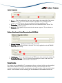
AlliedView-UM provides two types of Release Upgrade Operations: Release Upgrade
(AlliedWare +) and Release Upgrade (Other).
Devices that use AlliedWare™ software can be upgraded with new software release files
through the Release Upgrade (AlliedWare) Operation pane. The software release files for
these devices require special licenses in order to be properly installed.
To display this pane, click on the
Operations Selection pane.
AlliedView™-UM 2.0 USER’S GUIDE
button on the
Page 52 of 128
Devices that do not use AlliedWare™ or AlliedWare Plus™ software can be upgraded with
new software release files through the Release Upgrade (Other) Operation pane. The
software release files for these devices do not require any licenses.
To display this pane, click on the
Operation Selection pane.
AlliedView™-UM 2.0 USER’S GUIDE
button on the
Page 53 of 128
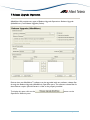
A. Creating a Release Upgrade Profile
Software Selection and Upload Parameters (AlliedWare)
1. License List Filename - Specify the license key list to use for the release. After
choosing the License List File, the release file to be used will be displayed in the
Release Filename field.
2. Release Filename - This is a read-only field that displays the filename of the software
release file that will be installed on the target device(s).
3. Upload Options - Choose one of the following options:
• Upload - Uploads the release file only.
• Upload and enable - Uploads and enables the release file only.
• Upload and set as temporary - Uploads, enables, and sets the release file as
the temporary release file.
• Upload and set as preferred - Uploads, enables and sets the release file as the
preferred release file.
4. File Deletion Options
• Delete old release files if memory space is insufficient checkbox - If the
devices to be upgraded have limited memory space (e.g. routers), there
might be a need to delete the existing release files in order to accommodate
the new release file. If a release file cannot be downloaded due to space
limitations and this option is checked, AlliedView-UM will delete any release
files residing in the device except for the currently installed release. If
unchecked, and there is not enough space to accommodate the new release
file, AlliedView-UM will fail the operation.
• Delete currently installed release file if memory space is insufficient
checkbox -This option will only be enabled if the above option is checked.
Otherwise, it will be grayed out. When this option is checked, AlliedView-UM
will also delete the currently installed release file if there is still insufficient
space in the device after deleting the other release files.
5. Reboot device after updating checkbox - If "Upload and set as temporary" or
"Upload and set as preferred" is chosen as the Upload Option, this checkbox will be
enabled. When checked, AlliedView-UM will reboot the device after performing the
software upgrade.
AlliedView™-UM 2.0 USER’S GUIDE
Page 54 of 128
1. Server - This is the address for the server that contains the release file. If the server
is a TFTP server, the server address should be specified as an IP address. If the
server is an HTTP server, the server address should be specified as a URL.
2. Destination - This sets the location where the new release file will be stored. This
can be set to FLASH or NVS.
3. Protocol - This specifies the protocol that the server supports. This can be set to
HTTP or TFTP.
Software Selection and Upload Parameters (AlliedWare+)
1. Release Filename - Specify the license software release file to be used.
2. Upload Options - Choose one of the following options:
•
•
Upload – Uploads the software release file only.
Upload and set as boot – Uploads and sets the software realease file as the
default boot image.
3. File Deletion Options
•
Delete old release files if memory space is insufficient checkbox – If the
devices to be upgraded have limited memory space, there might be a need to
delete the existing release files in order to accommodate the new release file.
If a release file cannot be downloaded due to space limitations and this
option is checked, AlliedView-UM will delete any release files residing in the
device except for the currently installed release. If unchecked, and there is
not enough space to accommodate the new release file, AlliedView-UM will
fail the operation.
4. Reboot device after updating checkbox – If “Upload and set as boot” is choosen as
the Upload Option, this checkbox will be enabled. When checked, AlliedView-UM
will reboot the device after performing the software upgrade.
AlliedView™-UM 2.0 USER’S GUIDE
Page 55 of 128
Upload Parameters
1. Server – This is the address for the server that contains the release file. If the server
is a TFTP server, the server address should be specified as an IP address. If the
server is an HTTP server, the server address should be specified as URL
2. Destination – this sets the location where the new release file will be stored. This
can be set to FLASH or NVS.
3. Protocol – This specifies the protocol that the server supports. This can be set to
HTTP of TFTP.
Software Selection and Upload Parametes (non-AlliedWare)
1. Release Filename – Specify the software file to be used.
2. Boot File – Specify the boot file to be used. This is only applicable to the AT-8000S
and AT-8000GS Family.
1. TFTP Server – This is the IP address of the TFTP server that contains the release file.
2. Destination Filename – This is a read-only field displays the name under which the
software release file is to be stored on the switch.
Device Selection
For devices that use AlliedWare™ management software, a license list file must be specified
before device selection can be performed. After selecting a license list file, the serial
numbers contained within will be checked against the serial numbers of the currently loaded
devices. The IP Address of each matching pair will be added to the Available Devices list.
AlliedView™-UM 2.0 USER’S GUIDE
Page 56 of 128
For devices that use non-AlliedWare™ management software, a release filename must be
specified. After specifying the release file, the Available Devices list will be populated with
the IP Addresses of the device definitions that can use the specified software release file.
Device selection is performed as follows:
1. Clicking the
button moves all selected/highlighted IP addresses from the
Available Devices list to the Selected Devices list.
2. Clicking the
button moves all IP addresses form the Available Devices list
to the Selected Devices list.
3. Clicking the
button moves all the selected/highlighted IP address from the
Selected Devices list to the Available Devices list.
4. Clicking the
button moves all the IP address from the Selected Devices list
to the Available Devices list.
5. The Family combo box will be populated with the Device Family names applicable
to the release file indicated in the Release Filename field. Clicking on this combo box
and selecting a specific Device Family will limit the contents of the Available Devices
list to that of the IP addresses of the devices that belong to the selected Device
Family.
6. The Group combo box will be populated with the device groups defined under the
Device Family selected in the previous step. Clicking on the Group combo box and
selecting a specific device group will limit the contents of the Available Devices list
to that of the IP addresses of the devices that belong to the selected Group.
However, the contents of the Selected Devices list will not be affected. For instance,
suppose that Selected Devices list contains IP addresses for devices that belong to
Group “A”. Then, Group “B” has been chosen in the Device Group combo box.
The Available Devices list will now only contain the IP addresses of the devices that
belong to Group “B”. However, the Selected Devices list will remain unchanged.
7. The Model combo box will be populated with the models supported by the Device
Family or Group selected in the previous step. Clicking on the Model combo box
and selecting a specific device model will limit the contents of the Available Devices
list to that of the IP addresses of the devices that belong to the selected Model.
However, the contents of the Selected Devices list will not be affected.
AlliedView™-UM 2.0 USER’S GUIDE
Page 57 of 128
B. Saving a Release Upgrade Profile
1. Click on the
button.
2. The Save Release Upgrade (AlliedWare), (AlliedWare+) or (Other) Profile dialog
box will be displayed.
3. Specify the filename.
4. Finally, click on the
button.
C. Loading a Release Upgrade Profile
1. Click on the
AlliedView™-UM 2.0 USER’S GUIDE
button.
Page 58 of 128
2. A confirmation dialog box will be displayed. Click
to proceed.
3. The Load Release Upgrade (AlliedWare), (AlliedWare+), or (Other) Profile dialog
box will be displayed. Specify the filename of the profile to be loaded.
4. Finally, click on the
button. AlliedView-UM will load the specified
Release Upgrade Operation profile.
NOTE:
The Release Upgrade (AlliedWare), (AlliedWare+), or (Other) Operation profile contains the Selected Devices list. While
loading, AlliedView-UM checks each item in this list against the currently loaded devices in the Device Families Pane. Only
entries that have a matching device in the Device Families Pane will be loaded and added to the Selected Devices list in the
Release Upgrade pane.
A summary window will be displayed indicating which entries were successfully added.
AlliedView™-UM 2.0 USER’S GUIDE
Page 59 of 128
D. Starting the Release Upgrade Operation
The Release Upgrade (AlliedWare), (AlliedWare+) or (Other) Operation can only be
started when the parameters have been properly set.
1. Click on the
button.
2. A progress window will be displayed, indicating the overall status of the operation.
When the Release Upgrade operation ends, the Operation Logs pane will be
updated to contain detailed information about the operation for each device.
3. Clicking the
or the
button will abort the Release Upgrade
(AlliedWare), (AlliedWare+), or (Other) operation. Depending on the time this
button is clicked, the operation may or may not complete for devices that are in
progress. Devices that were not able to complete the operation will have a status of
“Aborted”.
AlliedView™-UM 2.0 USER’S GUIDE
Page 60 of 128
NOTE:
Aborting an operation may leave some devices in an undesirable state.
7 Release Upgrade Operation
AlliedView™-UM 2.0 USER’S GUIDE
Page 61 of 128
8 Interim/Maintenance Release Upgrade Operation
Devices can be upgraded with a new Interim or Maintanance Release file through the
Interim/Maintenance Release Upgrade Operation pane.
To display this pane, click on the
Operations Selection pane.
button on the
The Interim/Maintenance Release Upgrade Operation is only applicable to devices that use
AlliedWare™ management software.
AlliedView™-UM 2.0 USER’S GUIDE
Page 62 of 128
A. Creating an Interim/ Maintenance Release Upgrade Profile
Software Selection
1. Interim/Maintenance Release Filename - Specify the interim/maintenance release file
to use.
2. Upload Options - Choose one of the following options:
•
•
•
•
Upload - Uploads the interim/maintenance release file only.
Upload and enable - Uploads and enables the interim/maintenance release file
only.
Upload and set as temporary - Uploads, enables, and sets the
interim/maintenance release file as the temporary release file.
Upload and set as preferred - Uploads, enables and sets the
interim/maintenance release file as the preferred release file.
3. File Deletion Options
•
•
Delete old release files if memory space is insufficient checkbox - If the
devices to be upgraded have limited memory space (e.g. routers), there
might be a need to delete the existing release files in order to accommodate
the new release file. If a release file cannot be downloaded due to space
limitations and this option is checked, AlliedView-UM will delete any release
files residing in the device except for the currently installed release. If
unchecked, and there is not enough space to accommodate the new release
file, AlliedView-UM will fail the operation.
Delete currently installed release file if memory space is insufficient
checkbox – This option will only be enabled if the above option is checked.
Otherwise, it will be grayed out. When this option is checked, AlliedViewUM will also delete the currently installed release file if there is still
insufficient space in the device after deleting the other release files.
4. Reboot device after updating checkbox - If "Upload and set as temporary" or
"Upload and set as preferred" is chosen as the Upload Option, this checkbox
will be enabled. When checked, AlliedView-UM will reboot the device after a
performing the software upgrade.
AlliedView™-UM 2.0 USER’S GUIDE
Page 63 of 128
Upload Parameters
1. Server - This is the address for the server that contains the interim/maintenance
release file. If the server is a TFTP server, the server address should be specified as
an IP address. If the server is an HTTP server, the server address should be specified
as a URL.
2. Destination - This sets the location where the new interim/maintenance release file
will be stored. This can be set to FLASH or NVS.
3. Protocol - This specifies the protocol that the server supports. This can be set to
HTTP or TFTP.
Device Selection
Before device selection can be performed, an Interim/Maintenance Release File must be
specified. After selecting an Interim/Maintenance Release File, the Available Devices list will
be populated with the IP addresses of the devices to which the specified interim release file
can be applied to.
Except for the above mentioned process, device selection is similar to that of the Release
Upgrade Operation pane.
B. Saving an Interim/Maintenance Release Upgrade Profile
1. Click on the
AlliedView™-UM 2.0 USER’S GUIDE
button.
Page 64 of 128
2. The Save Interim/Maintenance Release Upgrade Profile dialog box will be displayed.
3. Specify the filename.
4. Finally, click on the
button.
C. Loading an Interim/Maintenance Release Upgrade Profile
1. Click on the
button.
2. A confirmation box will be displayed. Click
AlliedView™-UM 2.0 USER’S GUIDE
to proceed.
Page 65 of 128
3. The Load Interim/Maintenance Release Upgrade Profile dialog box will be displayed.
Specify the filename of the profile to be loaded.
button. AlliedView-UM will load the specified
4. Finally, click on the
Interim/Maintenance Release Upgrade Operation profile.
NOTE:
The Interim/Maintenance Release Upgrade Operation profile contains the Selected Devices list. While loading, AlliedViewUM checks each item in this list against the currently loaded devices in the Device Families Pane. Only entries that have a
matching device in the Devices Families Pane will be loaded and added to the Selected Devices list in the
Interim/Maintenance Release Upgrade pane.
A summary window will be displayed indicating which entries were successfully added.
D. Starting the Interim/Maintenance Release Upgrade Operation
The Interim/Maintenance Release Upgrade Operation can only be started when the
parameters have been properly set.
1. Click on the
AlliedView™-UM 2.0 USER’S GUIDE
button.
Page 66 of 128
2. A progress window will be displayed, indicating the overall status of the operation.
When the Interim/Maintenance Release Upgrade operation ends, the Operation
Logs pane will be updated to contain detailed information about the operation for
each device.
or the
button will abort the Interim/Maintenance
3. Clicking the
Release Upgrade operation. Depending on the time this button is clicked, the
operation may or may not complete for devices that are in progress. Devices that
were not able to complete the operation will have a status of “Aborted”.
NOTE:
Aborting an operation may leave some devices in an undesirable state.
8 Interim/Maintenance Release Upgrade Operation
AlliedView™-UM 2.0 USER’S GUIDE
Page 67 of 128
9 Patch Upgrade Operation
Devices can be upgraded with patches through the Patch Upgrade Operation pane.
To display this pane, click on the
Selection pane.
button on the Operations
The Patch Upgrade Operation is only applicable to devices that use AlliedWare™
management software.
AlliedView™-UM 2.0 USER’S GUIDE
Page 68 of 128
A. Creating a Patch Upgrade Profile
Software Selection
1. Patch Filename - Specify the Patch file to use.
2. Upload Options - Choose one of the following options:
•
•
•
Upload - Uploads the Patch file only.
Upload and set as temporary - Uploads, enables, and sets the Patch file as the
temporary Patch file.
Upload and set as preferred - Uploads, enables and sets the Patch file as the
preferred Patch file.
3. File Deletion Options
•
•
Delete old patch files if memory space is insufficient checkbox - If the devices
to be upgraded have limited memory space (e.g. routers), there might be a
need to delete the existing patch files in order to accommodate the new
patch file. If a patch file cannot be downloaded due to space limitations and
this option is checked, AlliedView-UM will delete any patch files residing in
the device except for the currently installed patch. If unchecked, and there is
not enough space to accommodate the new patch file, AlliedView-UM will fail
the operation.
Delete currently installed patch file if memory space is insufficient checkbox
– This option will only be enabled if the above option is checked. Otherwise,
it will be grayed out. When this option is checked, AlliedView-UM will also
delete the currently installed patch file if there is still insufficient space in the
device after deleting the other patch files.
4. Reboot device after updating checkbox - If "Upload and set as temporary" or
"Upload and set as preferred" is chosen for the Upload Option, this
checkbox will be enabled. When checked, AlliedView-UM will reboot the
device after a performing the software upgrade.
AlliedView™-UM 2.0 USER’S GUIDE
Page 69 of 128
Upload Parameters
1. Server - This is the address for the server that contains the Patch file. If the server is
a TFTP server, the server address should be specified as an IP address. If the server
is an HTTP server, the server address should be specified as a URL.
2. Destination - This sets the location where the new Patch file will be stored. This can
be set to FLASH or NVS.
3. Protocol - This specifies the protocol that the server supports. This can be set to
HTTP or TFTP.
Device Selection
Before device selection can be performed, a patch file must be specified. After specifying a
patch file, the Available Devices list will be populated with the IP addresses of the devices to
which the specified patch file can be applied to.
Except for the above mentioned process, device selection is similar to that of the Release
Upgrade Operation pane.
B. Saving a Patch Upgrade Profile
1. Click on the
AlliedView™-UM 2.0 USER’S GUIDE
button.
Page 70 of 128
2. The Save Patch Upgrade Profile dialog box will be displayed.
3. When prompted, specify the filename.
4. Finally, click on the
button.
C. Loading a Patch Upgrade Profile
1. Click on the
button.
2. A confirmation box will be displayed. Click
AlliedView™-UM 2.0 USER’S GUIDE
to proceed.
Page 71 of 128
3. The Load Patch Upgrade Profile dialog box will be displayed. Specify the filename of
the profile to be loaded.
4. Finally, click on the
Upgrade Operation profile.
button. AlliedView-UM will load the specified Patch
NOTE:
The Patch Upgrade Operation profile contains the Selected Devices list. While loading, AlliedView-UM checks each item in
this list against the currently loaded devices in the Device Families Pane. Only entries that have a matching device in the
Device Families Pane will be loaded and added to the Selected Devices list in the Patch Upgrade Operation pane.
A summary window will be displayed indicating which entries were successfully added.
D. Starting the Patch Upgrade Operation
The Patch Upgrade Operation can only be started when the parameters have been properly
set.
1. Click on the
AlliedView™-UM 2.0 USER’S GUIDE
button.
Page 72 of 128
2. A progress window will be displayed, indicating the overall status of the operation.
When the Patch Upgrade operation ends, the Operation Logs pane will be updated
to contain detailed information about the operation for each device.
3. Clicking the
or the
button will abort the Patch Upgrade operation.
Depending on the time this button is clicked, the operation may or may not
complete for devices that are in progress. Devices that were not able to complete
the operation will have a status of “Aborted”.
NOTE:
Aborting an operation may leave some devices in an undesirable state.
9 Patch Upgrade Operation
AlliedView™-UM 2.0 USER’S GUIDE
Page 73 of 128
10 Configuration File Update
Device configurations can be updated through the Configuration File Update Operation
pane.
To display this pane, click on the
Selection pane.
AlliedView™-UM 2.0 USER’S GUIDE
button on the Operations
Page 74 of 128
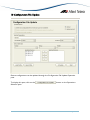
A. Creating a Configuration File Update Profile
Update Options
1. Upload Options - Choose one of the following options:
•
•
Upload - Uploads the Configuration file only.
Upload and set - Uploads and sets the configuration file as the Configuration
to be used by the device.
2. File Deletion Options
•
•
Delete old configuration files if memory space is insufficient checkbox - If the
devices to be upgraded have limited memory space (e.g. routers), there
might be a need to delete the existing Configuration files in order to
accommodate the new configuration file. If a Configuration file cannot be
downloaded due to space limitations and this option is checked, AlliedViewUM will delete any Configuration files residing in the device except for the
currently set Configuration file. If unchecked, and there is not enough space
to accommodate the new Configuration file, AlliedView-UM will fail the
operation.
Delete currently used configuration file if memory space is insufficient
checkbox - This option will only be enabled if the above option is checked.
Otherwise, it will be grayed out. When this option is checked, AlliedViewUM will also delete the currently set Configuration file if there is still
insufficient space in the device after deleting the other configuration files.
3. Reboot device after updating checkbox - If the “Upload and set” is chosen for the
Upload Option, this checkbox will be enabled. When checked, AlliedView-UM will
reboot the device after performing the update.
NOTE:
All elements defined in Upload Options panel are disregarded for the AT-8000, AT-8000/8POE, AT-8300GB, AT-9000,
AT-9410GB and AT-9700 families.
NOTE:
All elements defined in Upload Options panel, except "Upload" and "Upload and set", are disregarded for the AT-8400,
AT-8500 and AT-9400 families. All other update options apply only to devices that use AlliedWare™ and AlliedWare
Plus™ management software. During the Configuration File Update operation, AlliedView-UM will ignore the options that
are not applicable.
AlliedView™-UM 2.0 USER’S GUIDE
Page 75 of 128
NOTE:
For the AT-8000S and AT-8000GS Family,
•
Choosing “Upload” means that the contents of the specified configuration file will be added to those in the
running configuration of the device, thus, the loaded configuration will take effect as soon as the operation ends.
However, the loaded configuration will not be copied to the startup configuration which might be erased after
rebooting the device.
•
Choosing “Upload and Set” means that the contents of the specified configuration file will replace the startup
configuration of the device, thus, the loaded configuration will take effect after rebooting the device.
•
The “Delete old configuration files if memory space is insufficient” and “Delete currently used configuration file if
memory space is insufficient” options are disregarded by the application.
Upload Parameters
1. Server - This is the address for the server that contains the Configuration file.
If the server is a TFTP server, the server address should be specified as an IP
address. If the server is an HTTP server, the server address should be specified
as a URL.
2. Destination - This sets the location where the new Configuration file will be stored.
This can be set to FLASH or NVS.
3. Protocol - This specifies the protocol that the server supports. This can be set to
HTTP or TFTP.
NOTE:
The Destination field is not applicable to devices that use AlliedWare™ and non-AlliedWare Plus™ management software
and will be ignored during the Configuration File Update operation.
Since devices that use non-AlliedWare™ and non-AlliedWare Plus™ management software only support TFTP, the
Protocol field will also be ignored but will internally be set to "TFTP" during the Configuration File Update operation.
Device Selection
The Available Devices list will be initially populated with the IP addresses of the devices
which have a Configuration file specified in its device definition.
Except for the above mentioned process, device selection is similar to that of the Release
Upgrade Operation pane.
AlliedView™-UM 2.0 USER’S GUIDE
Page 76 of 128
B. Saving a Congfiguration File Update Profile
1. Click on the
button.
2. The Save Configuration File Update Profile dialog box will be displayed.
3. Specify the filename.
4. Finally, click on the
button.
C. Loading a Configuration File Update Profile
1. Click on the
AlliedView™-UM 2.0 USER’S GUIDE
button.
Page 77 of 128
2. A confirmation box will be displayed. Click
to proceed.
3. When prompted, specify the filename of the profile to load.
4. Finally, click on the
button. AlliedView-UM will load the specified
Configuration File Update Operation profile file.
NOTE:
The Configuration File Update profile contains the Selected Devices list. While loading, AlliedView-UM checks each item in
this list against the currently loaded devices in the Device Families Pane. Only entries that have a matching device in the
Device Families Pane will be loaded and added to the Selected Devices list in the Configuration File Update Operation
pane.
A summary window will be displayed indicating which entries were successfully added.
AlliedView™-UM 2.0 USER’S GUIDE
Page 78 of 128
D. Starting the Configuration File Update Operation
The Configuration File Update Operation can only be started when the parameters have
been properly set.
1. Click on the
button.
2. A progress window will be displayed, indicating the overall status of the operation.
When the Configuration File Update operation ends, the Operation Logs pane will
be updated to contain detailed information about the operation for each device.
3. Clicking the
or the
button will abort the Configuration File Update
operation. Depending on the time this button is clicked, the operation may or may
not complete for devices that are in progress. Devices that were not able to
complete the operation will have a status of “Aborted”.
AlliedView™-UM 2.0 USER’S GUIDE
Page 79 of 128
NOTE:
Aborting an operation may leave some devices in an undesirable state.
10 Configuration File Update
AlliedView™-UM 2.0 USER’S GUIDE
Page 80 of 128
11 Execute Script File
Script files can be uploaded and executed on target devices through the Execute Script File
Operation Pane
To display this pane, click on the
Operations Selection pane.
button on the
The Execute Script File Operation is only applicable to devices that use AlliedWare™ and
AlliedWarePlus™ management software.
A. Creating a Execute Script File Profile
Script File Selection
AlliedView™-UM 2.0 USER’S GUIDE
Page 81 of 128
1. Script Filename - Specify the Script file to use.
2. Upload Options - Choose one of the following options:
•
•
Upload - Uploads the Script file only.
Upload and execute - Uploads and executes the script file.
3. File Deletion Options
•
•
Overwrite existing script file checkbox - When this option is checked and
the device already has a script file with the same filename, then the script file
on the device will be overwritten with the new script file. Otherwise, if this
option is un-checked, and the same condition occurs, then AlliedView-UM
will fail the operation.
Delete old script files if memory space is insufficient checkbox - When this
option is checked, and the device cannot accomodate the new script file due
to lack of memory space, AlliedView-UM will also delete the all script files
(*.scp) if there is insufficient space in the device. Otherwise, if this option is
un-checked and there is insufficient memory space, then AlliedView-UM will
fail the operation.
Upload Parameters
1. Server - This is the address for the server that contains the Script file. If the server
is a TFTP server, the server address should be specified as an IP address. If the
server is an HTTP server, the server address should be specified as a URL.
2. Destination - This sets the location where the new Script file will be stored. This can
be set to FLASH or NVS.
3. Protocol - This specifies the protocol that the server supports. This can be set to
HTTP or TFTP.
Device Selection
The Available Devices list will be initially populated with IP addresses of applicable devices.
Except for the above mentioned process, device selection is similar to that of the Reboot
Device Operation pane.
AlliedView™-UM 2.0 USER’S GUIDE
Page 82 of 128
B. Saving an Execute Script File Profile
1. Click on the
button.
2. The Save Execute Script File Profile dialog box will be displayed.
3. Specify the filename.
4. Finally, click on the
button.
C. Loading an Execute Script File Profile
1. Click on the
AlliedView™-UM 2.0 USER’S GUIDE
button.
Page 83 of 128
2. A confirmation box will be displayed. Click
to proceed.
3. When prompted, specify the filename of the profile to load.
4. Finally, click on the
button. AlliedView-UM will load the specified
Execute Script File Operation profile file.
NOTE:
The Execute Script File profile contains the Selected Devices list. While loading, AlliedView-UM checks each item in this list
against the currently loaded devices in the Device Families Pane. Only entries that have a matching device in the Device
Families Pane will be loaded and added to the Selected Devices list in the Execute Script File Operation pane.
A summary window will be displayed indicating which entries were successfully added.
AlliedView™-UM 2.0 USER’S GUIDE
Page 84 of 128
D. Starting the Execute Script File Operation
The Execute Script File Operation can only be started when the parameters have been
properly set.
1. Click on the
button.
2. A progress window will be displayed, indicating the overall status of the operation.
When the Execute Script File operation ends, the Operation Logs pane will be
updated to contain detailed information about the operation for each device.
3. Clicking the
or the button will abort the Execute Script File operation.
Depending on the time this button is clicked, the operation may or may not
complete for devices that are in progress. Devices that were not able to complete
the operation will have a status of “Aborted”.
AlliedView™-UM 2.0 USER’S GUIDE
Page 85 of 128
NOTE:
Aborting an operation may leave some devices in an undesirable state.
11 Execute Script File
AlliedView™-UM 2.0 USER’S GUIDE
Page 86 of 128
12 GUI Resource File Update
Device GUI Resources can be updated through the GUI Resource File Update Operation
pane.
To display this pane, click on the
Selection pane.
button on the Operations
The GUI Resource File Update Operation is only applicable to devices that use
AlliedWare™ management software.
AlliedView™-UM 2.0 USER’S GUIDE
Page 87 of 128
A. Creating a GUI Resource File Update Profile
Software Selection
1. GUI Resource Filename - Specify the GUI Resource file to use. There are two types
of GUI Resource files:
•
•
Old Type – These are GUI Resource files for the following software releases:
o Versions 2.4.1 and below for the AT-AR410, AT-AR700 Series,
SwitchBlade Series, AT-9800 Series, and Rapier Series
New Type – These are GUI Resource files for the following software
releases:
o Versions 2.5.1 and above for the AT-AR410, AT-AR700 Series,
SwitchBlade Series, AT-9800 Series, and Rapier Series
2. Upload Options - Choose one of the following options:
•
•
•
Upload - Uploads the GUI Resource file only.
Upload and set as temporary - Uploads and sets the GUI Resource file as
temporary. (This option will be disabled if an old GUI Resource file is
specified.)
Upload and set as preferred - Uploads and sets the GUI Resource file as
preferred. (This option will be disabled if an old GUI Resource file is
specified.)
3. File Deletion Options
•
Delete old GUI Resource files if memory space is insufficient checkbox - If
the devices to be upgraded have limited memory space (e.g. routers), there
might be a need to delete the existing GUI Resource files in order to
accommodate the new GUI Resource file. If a GUI Resource file cannot be
downloaded due to space limitations and this option is checked, the
AlliedView-UM will delete any GUI Resource files residing in the device
except for the currently set GUI Resource file. If unchecked, and there is not
enough space to accommodate the new GUI Resource file, AlliedView-UM
will fail the operation.
AlliedView™-UM 2.0 USER’S GUIDE
Page 88 of 128
•
Delete currently used GUI Resource file if memory space is insufficient
checkbox - This option will only be enabled if the above option is checked.
Otherwise, it will be grayed out. When this option is checked, the
AlliedView-UM will also delete the currently set GUI Resource file if there is
still insufficient space in the device after deleting the other GUI Resource
files.
4. Reboot device after updating checkbox - If an old GUI Resource File is specified,
this option will be enabled. Otherwise if the specified GUI Resource File is new,
this checkbox will only be enabled if “Upload and set as temporary” or “Upload and
set as preferred” is chosen for the Upload Option. When checked, AlliedView-UM
will reboot the device after performing the update.
Upload Parameters
1. Server - This is the address for the server that contains the GUI Resource file. If the
server is a TFTP server, the server address should be specified as an IP address.
If the server is an HTTP server, the server address should be specified as a URL.
2. Destination - This sets the location where the new GUI Resource file will be stored.
This can be set to FLASH or NVS.
3. Protocol - This specifies the protocol that the server supports. This can be set to
HTTP or TFTP.
Device Selection
Before device selection can be performed, a GUI Resource file must be specified. After
selecting a GUI Resource file, the Available Devices list will be populated with the IP
addresses of the devices to which the specified GUI Resource file can be applied to.
Except for the above mentioned process, device selection is similar to that of the Release
Upgrade Operation pane.
B. Saving a GUI Resource File Update Profile
1. Click on the
AlliedView™-UM 2.0 USER’S GUIDE
button.
Page 89 of 128
2. The Save GUI Resource File Update Profile dialog box will be displayed.
3. Specify the filename.
4. Finally, click on the
button.
C. Loading a GUI Resource File Update Profile
1. Click on the
button.
2. A confirmation box will be displayed. Click
AlliedView™-UM 2.0 USER’S GUIDE
to proceed.
Page 90 of 128
3. The Load GUI Resource File Update Profile dialog box will be displayed.
4. Specify the filename of the profile to be loaded.
5. Finally, click on the
button. AlliedView-UM will load the specified
GUI Resource File Update Operation profile.
NOTE:
The GUI Resource File Update operation profile contains the Selected Devices list. While loading, AlliedView-UM checks
each item in this list against the currently loaded devices in the Device Families Pane. Only entries that have a matching
device in the Device Families Pane will be loaded and added to the Selected Devices list in the GUI Resource File Update
Operation pane.
A summary window will be displayed indicating which entries were successfully added.
D. Starting the GUI Resource File Update Operation
The GUI Resource File Update Operation can only be started when the parameters have
been properly set.
1. Click on the
AlliedView™-UM 2.0 USER’S GUIDE
button.
Page 91 of 128
2. A progress window will be displayed, indicating the overall status of the operation.
When the GUI Resource File Update operation ends, the Operation Logs pane will
be updated to contain detailed information about the operation for each device.
3. Clicking the
or the
button will abort the GUI Resource File Update
operation. Depending on the time this button is clicked, the operation may or may
not complete for devices that are in progress. Devices that were not able to
complete the operation will have a status of “Aborted”.
NOTE:
Aborting an operation may leave some devices in an undesirable state.
12 GUI Resource File Update
AlliedView™-UM 2.0 USER’S GUIDE
Page 92 of 128
13 Help File Update
The Command Line Interface Help of the devices can be updated through the Help File
Update Operation pane.
To display this pane, click on the
Selection pane.
button on the Operations
The Help File Update Operation is only applicable to devices that use AlliedWare™
management software.
AlliedView™-UM 2.0 USER’S GUIDE
Page 93 of 128
A. Creating a Help File Update Profile
Software Selection
1. Help Filename - Specify the Help file to use.
2. Upload Options - Choose one of the following options:
•
•
Upload - Uploads the Help file only.
Upload and set - Uploads and sets the Help file.
3. File Deletion Options
•
•
Delete old help files if memory space is insufficient checkbox - If the devices
to be upgraded have limited memory space (e.g. routers), there might be a
need to delete the existing Help files in order to accommodate the new Help
file. If a Help file cannot be downloaded due to space limitations and this
option is checked, AlliedView-UM will delete any Help files residing in the
device except for the currently set Help file. If unchecked, and there is not
enough space to accommodate the new Help file, AlliedView-UM will fail the
operation.
Delete currently used help file if memory space is insufficient checkbox This option will only be enabled if the above option is checked. Otherwise, it
will be grayed out. When this option is checked, AlliedView-UM will also
delete the currently set Help file if there is still insufficient space in the device
after deleting the other Help files.
Upload Parameters
1. Server - This is the address for the server that contains the Help file. If the server is
a TFTP server, the server address should be specified as an IP address. If the server
is an HTTP server, the server address should be specified as a URL.
2. Destination - This sets the location where the new Help file will be stored. This can
be set to FLASH or NVS.
3. Protocol - This specifies the protocol that the server supports. This can be set to
HTTP or TFTP.
AlliedView™-UM 2.0 USER’S GUIDE
Page 94 of 128
Device Selection
Before device selection can be performed, a Help file must be specified. After specifying a
Help file, the Available Devices list will be populated with the IP addresses of the devices to
which the Help file can be applied to.
Except for the above mentioned process, device selection is similar to that of the Release
Upgrade Operation pane.
B. Saving a Help File Update Profile
1. Click on the
button.
2. The Save Help File Update Profile dialog box will be displayed.
3. Specify the filename.
4. Finally, click on the
AlliedView™-UM 2.0 USER’S GUIDE
button.
Page 95 of 128
C. Loading a Help File Update Profile
1. Click on the
button.
2. A confirmation box will be displayed. Click
to proceed.
3. The Load Help File Update Profile dialog box will be displayed.
4. Specify the filename of the profile to be loaded.
5. Finally, click on the
button. AlliedView-UM will load the specified Help
File Update Operation profile.
AlliedView™-UM 2.0 USER’S GUIDE
Page 96 of 128
NOTE:
The Help File Update Operation profile contains the Selected Devices list. While loading, AlliedView-UM checks each item
in this list against the currently loaded devices in the Device Families Pane. Only entries that have a matching device in the
Device Families Pane will be loaded and added to the Selected Devices list in the Help File Update pane.
A summary window will be displayed indicating which entries were successfully added.
D. Starting the Help File Update Operation
The Help File Update Operation can only be started when the parameters have been
properly set.
1. Click on the
button.
2. A progress window will be displayed, indicating the overall status of the operation.
When the Help File Update operation ends, the Operation Logs pane will be
updated to contain detailed information about the operation for each device.
AlliedView™-UM 2.0 USER’S GUIDE
Page 97 of 128
3. Clicking the
or the
button will abort the Help File Update
Operation. Depending on the time this button is clicked, the operation may
or may not complete for devices that are in progress. Devices that were not able
to complete the operation will have a status of “Aborted”.
NOTE:
Aborting an operation may leave some devices in an undesirable state.
13 Help File Update
AlliedView™-UM 2.0 USER’S GUIDE
Page 98 of 128
14 Enable Feature Operations
Device features can be enabled through the Enable Features Operation pane.
To display this pane, click on the
Selection pane.
button on the Operations
The Enable Features Operation is only applicable to devices that use AlliedWare™ and
AlliedWare Plus™ management software.
A. Creating an Enable Features Profile
Software Selection
1. License List Filename - Specify the license list file to use for this operation. After
choosing the License List File, the features to be enabled will be displayed in the
Feature field.
2. Feature – This is a read-only field that displays the name of the feature that will be
enabled on the target device(s).
AlliedView™-UM 2.0 USER’S GUIDE
Page 99 of 128
Device Selection
Before device selection can be performed, a license list file must be specified. After selecting
a license list file, the serial numbers contained within will be checked against the serial
numbers of the currently loaded devices. The IP Address of each matching pair will be
added to the Available Devices list.
Except for the above mentioned process, device selection is similar to that of the Release
Upgrade Operation pane.
B. Saving an Enable Feature Profile
1. Click on the
button.
2. The Save Enable Features Profile dialog box will be displayed.
3. Specify the filename.
4. Finally, click on the
AlliedView™-UM 2.0 USER’S GUIDE
button.
Page 100 of 128
C. Loading an Enable Features Profile
1. Click on the
button.
2. A confirmation box will be displayed. Click
to proceed.
3. The Load Enable Features Profile dialog box will be displayed.
4. Specify the filename of the profile to be loaded.
5. Finally, click on the
Features Operation profile.
AlliedView™-UM 2.0 USER’S GUIDE
button. AlliedView-UM will load the specified Enable
Page 101 of 128
NOTE:
The Enable Features Operation profile contains the Selected Devices list. While loading, AlliedView-UM checks each item
in this list against the currently loaded devices in the Device Families Pane. Only entries that have a matching device in the
Device Families Pane will be loaded and added to the Selected Devices list in the Enable Features pane.
A summary window will be displayed indicating which entries were successfully added.
D. Starting the Enable Features Operation
The Enable Features Operation can only be started when the parameters have been
properly set.
1. Click on the
button.
2. A progress window will be displayed, indicating the overall status of the operation.
When the Enable Features Operation ends, the Operation Logs pane will be updated
to contain detailed information about the operation for each device.
AlliedView™-UM 2.0 USER’S GUIDE
Page 102 of 128
3. Clicking the
or the
button will abort the Enable Features Operation.
Depending on the time this button is clicked, the operation may or may not
complete for devices that are in progress. Devices that were not able to complete
the operation will have a status of “Aborted”.
NOTE:
Aborting an operation may leave some devices in an undesirable state.
14 Enable Feature Operations
AlliedView™-UM 2.0 USER’S GUIDE
Page 103 of 128
15 Reboot Device
Devices can be rebooted through the Reboot Device Operation pane.
To display this pane, click on the
Selection pane.
button on the Operations
A. Creating a Reboot Device Profile
Device Selection
Device Selection is similar to that of the Release Upgrade Operation pane.
B. Saving a Reboot Device Profile
1. Click on the
AlliedView™-UM 2.0 USER’S GUIDE
button.
Page 104 of 128
2. The Save Reboot Device Profile dialog box will be displayed.
3. Specify the filename.
4. Finally, click on the
button.
C. Loading a Reboot Device Profile
1. Click on the
button.
2. A confirmation box will be displayed. Click
AlliedView™-UM 2.0 USER’S GUIDE
to proceed.
Page 105 of 128
3. The Load Reboot Device Profile dialog box will be displayed.
4. Specify the filename of the profile to be loaded.
button. AlliedView-UM will load the specified
5. Finally, click on the
Reboot Device profile.
NOTE:
The Reboot Device Operation profile contains the Selected Devices list. While loading, AlliedView-UM checks each item
in this list against the currently loaded devices in the Device Families Pane. Only entries that have a matching device in the
Device Families Pane will be loaded and added to the Selected Devices list in the Reboot Device Operation pane.
A summary window will be displayed indicating which entries were successfully added.
D. Starting the Reboot Device Operation
1. Click on the
AlliedView™-UM 2.0 USER’S GUIDE
button.
Page 106 of 128
2. A progress window will be displayed, indicating the overall status of the operation.
When the Reboot Device Operation ends, the Operation Logs pane will be updated
to contain detailed information about the operation for each device.
3. Clicking the
or the
button will abort the Reboot Device Operation.
Depending on the time this button is clicked, the operation may or may not
complete for devices that are in progress. Devices that were not able to complete
the operation will have a status of “Aborted”.
NOTE
Aborting an operation may leave some devices in an undesirable state.
15 Reboot Device
AlliedView™-UM 2.0 USER’S GUIDE
Page 107 of 128
16 Audit Trail
Each device definition has an audit trail that contains a chronological record of the
operations that were performed on it.
A. Viewing the Audit Trail
To view a device’s audit trail, right-click on a device definition from the Device Families
Pane. Select “View Device Audit Trail” from the context menu to display the Device Audit
Trail dialog box for that device.
Audit Record
Each entry in the audit trail is called an Audit Record. An audit record contains the
following information:
1. Date – This is the date and time when the operation was performed.
2. Operation – This is the operation that was performed. This can be any of the
following:
AlliedView™-UM 2.0 USER’S GUIDE
Page 108 of 128
•
•
•
•
•
•
•
•
•
•
•
•
Release Upgrade (AlliedWare)
Release Upgrade (AlliedWare+)
Release Upgrade (Other)
Patch Upgrade
Interim/Maintenance Release Upgrade
Configuration File Update
Execute Script File
GUI Resource File Update
Help File Update
Enable Features
Reboot Device
Rollback
3. Operation Properties – These are the parameters that were used for the operation.
4. Result – This is the result of the operation for that device.
NOTE:
If the IP Address of a device definition is changed, then the device definition may no longer be referring to the same device
managed by AlliedView-UM. When this happens, you will be prompted whether or not you want to clear or retain the
current Audit Trail.
16 Audit Trail
AlliedView™-UM 2.0 USER’S GUIDE
Page 109 of 128
17 Schedule Operation
Operations can be executed at a specified time using the Operation Scheduling function.
A. How to Schedule an Operation
To schedule an operation, you must first define an operation profile using the methods
discussed in the previous sections of this document.
Once you have created your profile, click on the
the Schedule Task dialog box.
button. This will display
On the Task Name field, enter a name for the operation to be scheduled. Enter the date
and time when the operation will be executed on the Time Schedule field. To set the time,
double click on an element (e.g. Double click on the “09” of the “09 Jun 2004…” on the
image above.) to highlight it. You may then use the spin control to change the value.
Finally, click on the OK button.
AlliedView™-UM 2.0 USER’S GUIDE
Page 110 of 128
B. Viewing Tasks
You may view the list of scheduled operations using the View Tasks dialog box. Click on
Tools->View Tasks to display the dialog box.
Task
Each task contains the following information:
1. Task Name – This is the name that was entered in the Task Name field of the
Schedule Task dialog box.
2. Operation – This is the operation that will be performed. This can be any of the
following:
•
•
•
•
•
•
•
Release Upgrade (AlliedWare)
Release Upgrade (AlliedWare+)
Release Upgrade (Other)
Patch Upgrade
Interim/Maintenance Release Upgrade
Configuration File Update
Execute Script File
AlliedView™-UM 2.0 USER’S GUIDE
Page 111 of 128
•
•
•
•
GUI Resource File Update
Help File Update
Enable Features
Reboot Device
3. Operation Properties – These are the parameters that will be used for the
operation.
4. Time of Execution – This is the date and time when the task will be started.
5. Status – This is the status of the task. It can be any of the following:
•
•
•
•
Pending – The task is waiting to be executed.
Done – The task has already been executed.
Aborted – The user has aborted the task.
Expired – The task was not started on the specified time of execution.
C. Editing Tasks
A task may be edited if the status is "Pending" or "Expired".
1. Select an entry from the task list.
AlliedView™-UM 2.0 USER’S GUIDE
Page 112 of 128
2. Click on the
button to display the Edit Task dialog.
3. On the Edit Task dialog, there are two ways to modify the task:
•
Change the execution date and time – You may specify a new date and time
for the operation to be executed. After specifying a new date and time, the
entry of the scheduled operation will be updated in the task list.
•
Start Now – Click on the
immediately.
button to start the operation
D. Aborting a Task
A task that has a “Pending” status can be aborted. Once aborted, that task will no longer
be executed on its specified time.
AlliedView™-UM 2.0 USER’S GUIDE
Page 113 of 128
1. To abort a task, select the task from the task list.
2. After making the selection, click on the
3. A confirmation box will be displayed. Click on
AlliedView™-UM 2.0 USER’S GUIDE
button.
to abort the task.
Page 114 of 128
E. Deleting a Task
A task can be removed from the task list.
1. To delete a task, select the task to be removed from the task list.
2. After selecting the task to be deleted, click on the
3. A confirmation box will be displayed. Click on
button.
to delete the task.
17 Schedule Operations
AlliedView™-UM 2.0 USER’S GUIDE
Page 115 of 128
18 Rollback
A. Rollbacks and the Audit Trail
Rollbacks are based on the contents of a device’s audit trail. A rollback of an operation can
only be performed if the device’s audit trail contains a record of an operation that can be
used as a reference to rollback to.
For instance, assume that a device definition contains the following audit trail:
#
1
2
3
4
5
6
AUDIT
Release Upgrade 1
Patch Upgrade 1
Configuration File Update 1
Patch Upgrade 2
Release Upgrade 2
Release Upgrade 3
In the example above, “Release Upgrade 3” is the last operation performed on the device.
If a rollback operation is performed, AlliedView-UM will try to find the Release Upgrade
operation that was performed prior to Release Upgrade 3. In this case, it is Release
Upgrade 2. During the rollback, AlliedView-UM will re-execute the Release Upgrade 2
operation recorded in the audit trail.
Now, let’s say that a device contains the following audit trail:
#
1
2
3
4
5
AUDIT
Patch Upgrade 1
Patch Upgrade 2
Configuration File Update 1
Patch Upgrade 3
Release Upgrade 1
In the example above, “Release Upgrade 1” is the last operation performed on the device.
If a rollback operation is performed, AlliedView-UM will try to find the Release Upgrade
operation that was performed prior to Release Upgrade 1. However, as indicated in the
table above, there are no Release Upgrades to rollback to. In this case, a rollback operation
cannot be performed.
AlliedView™-UM 2.0 USER’S GUIDE
Page 116 of 128
B. Special Rules on Rollbacks
If the last entry in the Audit Trail is a Reboot Device operation or an Execute Script File
operation, then AlliedView-UM will locate the most recent non-Reboot Device operation
entry in the Audit Trail. That entry will be the one to be rolled back.
#
1
2
3
4
5
6
7
8
AUDIT
Release Upgrade 1
Patch Upgrade 1
Configuration File Update 1
Patch Upgrade 2
Release Upgrade 2
Release Upgrade 3
Reboot Device
Reboot Device
In the example above, the most recent non-Reboot entry in the Audit Trail is “Release
Upgrade 3”. “Release Upgrade 3” will be the operation to be rolled back. If the last entry
on the Audit Trail is a Rollback operation, then a Rollback cannot be performed.
C. Performing a Rollback on a Device
1. Right click on a device definition in the Device Families Pane to display the device
context menu and select “Rollback Last Operation”.
AlliedView™-UM 2.0 USER’S GUIDE
Page 117 of 128
2. If it is possible to perform a rollback operation, the Device Rollback dialog box
will appear. This dialog box will show the following information:
•
•
•
Operation – This is the operation that will be rolled back.
Current Properties – These are the properties of the operation that will
be rolled back.
Target Properties – These are the properties of the operation that will
be performed for the rollback operation.
3. Click the
button to perform the rollback.
4. When the rollback operation is complete, a “Rollback successful” message will be
displayed. If the rollback failed, a “Rollback failed” message will be displayed instead.
For more details on the results of the Rollback operation, you may view the
Operation Logs pane.
AlliedView™-UM 2.0 USER’S GUIDE
Page 118 of 128
D. Performing a Rollback on an Operation Profile
It is possible to perform a rollback of the last Operation Profile that was executed.
When this is done, a rollback operation will be performed on the devices that were
included in the Operation Profile. Please refer to the Performing a Rollback on a
Device section.
If the last operation performed is a Reboot Operation Profile, Rollback Last Operation
Profile or Execute Script File Profile then this type of rollback cannot be performed.
1. To rollback the last operation performed, select Tools->Rollback Last Operation
Profile from the main menu.
AlliedView™-UM 2.0 USER’S GUIDE
Page 119 of 128
2. This will display the Rollback Last Operation Profile dialog box. This dialog box will
display the following information:
•
•
•
•
•
Operation – This is the operation that will be rolled back.
Operation Properties – These are the properties of the operation that will
be rolled back.
Date & Time – This is the date and time when the operation profile was
executed.
Device – This is the IP Address of the devices that were included in the
operation profile.
Target Properties – These are the properties of the operation that will be
performed for the rollback operation.
AlliedView™-UM 2.0 USER’S GUIDE
Page 120 of 128
3. Click the
button to perform the rollback operation.
4. When the rollback operation is complete, a summary window will be displayed. It will
show the results of the rollback operation for each of the devices. For more details
on the results of the Rollback operation, you may view the Operation Logs pane.
18 Rollback
AlliedView™-UM 2.0 USER’S GUIDE
Page 121 of 128
19 License Registration
AlliedView-UM application will run in demo mode if a license key has not yet been
registered or if a duplicate license key has been detected. A duplicate license is detected if
the number of computers currently running AlliedView-UM that are registered with the
same license key exceeds the maximum allowed by that license key. There is no expiration
period for the demo mode version.
To get the full functionality of AlliedView-UM 2.0, user must enter a license in Help >
License Registration. To obtain a License Key, contact your authorized Allied Telesis sales
representative. Below is the window that will pop-up when in demo mode:
Until a user register a valid License Key, AV-UM application will be running in demo mode.
While in demo mode, all operations performed are simulated.
A. Registering a License
To register your license, follow these steps:
AlliedView™-UM 2.0 USER’S GUIDE
Page 122 of 128
1. Select the Help->License Registration option from the main menu to display the
License Registration window.
2. Click on the
button to display the Input License window.
3. Enter the License Key and the Company Name printed on the Software Feature
Registration Form or Software Certificate provided to you by an Allied Telesis sales
representative and click the
button.
4. The License Registration window will now display your registered license. You can
close this window by clicking on the
AlliedView™-UM 2.0 USER’S GUIDE
button.
Page 123 of 128
B. Modifying a License
Method 1:
1. On the License Registration window, click on the
button.
2. The Modify Lecense window will be displayed. After modifying the License Key and
button.
the Company Name, click on the
3. The License Registration window will now display your modified License Key and
Company Name. You can close this window by clicking on the
AlliedView™-UM 2.0 USER’S GUIDE
button.
Page 124 of 128
Method 2:
1. On the License Refistration window, double-click on the
License window.
to display the Modify
2. After modifying the License Key and the Company Name, click on the
button.
3. The License Registration window will now display your modified License Key and
Company Name. You can close this window by clicking on the
button.
19 License Registration
AlliedView™-UM 2.0 USER’S GUIDE
Page 125 of 128
20 Options
The Options menu provides functions for customizing the appearance and behavior of the
application.
A. View Settings
The general appearance of the Device Family tree can be modified via the View Settings.
By default, the Device Family Tree only displays the IP Addresses of the device definitions.
By selecting the Options->Show System Name option, the Device Family Tree will also
display the System Names of the device definitions in addition to the IP Addresses.
Also, the entries within a Device Group in the Device Family Tree are sorted by their IP
Addresses by default. By selecting the Options->Sort By System Name option, the entries
will be displayed according to their System Name. Note that it is only possible to select this
option when the Show System Name option is enabled.
AlliedView™-UM 2.0 USER’S GUIDE
Page 126 of 128
B. Thread Settings
This dialog box allows you to fine tune the performance and resource usage of AlliedView-UM.
The No. of Threads field controls the number of active device connections that AlliedView-UM
will try to establish during an Operation Profile and Import/Update Operation execution.
For instance, if this value is set to 10 then AlliedView-UM will limit the active connections to only
10 sessions. This allows AlliedView-UM to effectively run on environments with low
network bandwidth. The No. of Threads field can be set to any value in the range [1-100] inclusive.
20 Options
AlliedView™-UM 2.0 USER’S GUIDE
Page 127 of 128
© 1998-2009 Allied Telesis K. K.
All rights reserved. No part of this publication may be reproduced without prior written permission from
Allied Telesis, K. K.
Microsoft is a registered trademark of Microsoft Corporation. Netscape Navigator is a registered trademark
of Netscape Communications Corporation. All other product names, company names, logos or other
designations mentioned herein are trademarks or registered trademarks of their respective owners.
Allied Telesis K. K. reserves the right to make changes in specifications and other information contained in this
document without prior written notice. The information provided herein is subject to change without
notice. In no event shall Allied Telesis K. K. be liable for any incidental, special, indirect, or consequential
damages whatsoever, including but not limited to lost profits, arising out of or related to this manual or the
information contained herein, even if Allied Telesis K. K. has been advised of, known, or should have known,
the possibility of such damages.
PN 613-000381 Rev D
USA Headquarters | 19800 North Creek Parkway | Suite 200 | Bothell | WA 98011 | USA | T: +1 800 424 4284 | F: +1 425 481 3895
European Headquarters | Via Motta 24 | 6830 Chiasso | Switzerland | T: +41 91 69769.00 | F: +41 91 69769.11
Asia-Pacific Headquarters | 11 Tai Seng Link | Singapore | 534182 | T: +65 6383 3832 | F: +65 6383 3830
www.alliedtelesis.com