1
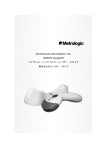
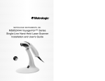
METROLOGIC INSTRUMENTS, INC. MS9535 VoyagerBT Wireless Hand-Held Laser Scanner Installation and User’s Guide LOCATIONS CORPORATE HEADQUARTERS North America Metrologic Instruments, Inc. 90 Coles Road Blackwood, NJ 08012-4683 Customer Service: 1-800-ID-METRO Tel: 856-228-8100 Fax: 856-228-6673 Email: [email protected] Internet: www.metrologic.com EUROPEAN HEADQUARTERS Germany, Middle East and Africa Metrologic Instruments GmbH Dornierstrasse 2 82178 Puchheim b. Munich, Germany Tel: +49 89 89019 0 Fax: +49 89 89019 200 Email: [email protected] Germany Email: [email protected] Spain Metrologic Eria lbérica SL Julián Camarillo 29, D-1 Edificio Diapasón 28037 Madrid Tel: +34 913 272 400 Fax: +34 913 273 829 Email: [email protected] Italy Metrologic Instruments Italia srl Via Emilia 70 40064 Ozzano dell’Emilia (BO) Tel: +39 0 51 6511978 Fax: +39 0 51 6521337 Email: [email protected] France Metrologic Eria France SA 69 Rue de la Belle Etoile ZI Paris Nord II, BP 50057 95947 – ROISSY CDG CEDEX Tel: +33 (0) 1 48.63.78.78 Fax: +33 (0) 1 48.63.24.94 Email: [email protected] United Kingdom Metrologic Instruments UK Limited 58 Tempus Business Centre Kingsclere Road, Basingstoke Hampshire RG21 6XG Tel: +44 (0) 1256 365900 Fax: +44 (0) 1256 365955 Email: [email protected] Russia Metrologic Russia Bolshaya Novodmitrovskaya 14 RU-125015 Moscow, Russia Tel: +7 095 50 93 485 Email: [email protected] Singapore Metrologic Asia (Pte) Ltd No. 8 Kaki Bukit Place 4th Floor Singapore 416186 Tel: 65-6842-7155 Fax: 65-6842-7166 Email: [email protected] China Metro (Suzhou) Technologies Co., Ltd. 221 Xing Hai Street Suzhou Industrial Park Suzhou, China 215021 Tel: 86-512-62572511 Fax: 86-512-62571517 Email: [email protected] Japan Metrologic Japan Co., Ltd. Matsunoya Building, 6 Floor 3-14-8 Higashiueno Taitou-Ku, Tokyo 110-0015 Japan Tel: 81-03-3839-8511 Fax: 81-03-3839-8519 Email: [email protected] Brazil Metrologic do Brasil Ltda. Rua da Paz 2059 CEP 04713-002 Chácara Santo Antônio São Paulo, SP, Brasil Tel: 55-11-5182-8226 Fax: 55-11-5182-8315 Email: [email protected] Outside Brazil Metrologic South America Rua da Paz 2059 CEP 04713-002 Chácara Santo Antônio São Paulo, SP, Brasil Tel: 55-11-5182-7273 Fax: 55-11-5182-7198 Email: [email protected] ASIA SOUTH AMERICA Copyright © 2003 by Metrologic Instruments, Inc. All rights reserved. No part of this work may be reproduced, transmitted, or stored in any form or by any means without prior written consent, except by reviewer, who may quote brief passages in a review, or provided for in the Copyright Act of 1976. Products and brand names mentioned in this document are trademarks of their respective companies. ii TABLE OF CONTENTS Introduction........................................................................................................... 1 Scanner and Accessories..................................................................................... 2 Quick Start............................................................................................................ 3 RS232 and Light Pen Scanner Installation........................................................... 5 Keyboard Wedge Scanner Installation ................................................................. 6 USB Scanner Installation ..................................................................................... 7 Establish Communication Between Scanner and Cradle ..................................... 8 Charging the Scanner .......................................................................................... 9 Receiver / Charger Cradle.................................................................................. 11 Cradle Parts ....................................................................................................... 12 Scanner Parts..................................................................................................... 13 Audible Indicators............................................................................................... 14 Visual Indicators ................................................................................................. 15 Failure Modes..................................................................................................... 17 Programming Modes .......................................................................................... 18 Upgrading the Flash ROM Firmware .................................................................. 19 Labels................................................................................................................. 20 Maintenance....................................................................................................... 20 Depth of Field ..................................................................................................... 21 IR Activation ....................................................................................................... 22 Connecting to other Bluetooth Devices .............................................................. 23 Troubleshooting Guide ....................................................................................... 25 Design Specifications ......................................................................................... 29 Default Settings .................................................................................................. 30 Cradle and Cable Terminations Cradle Pinout Connections............................................................................. 35 Cable Connector Configurations .................................................................... 36 Limited Warranty ................................................................................................ 38 Notices ............................................................................................................... 39 Patents ............................................................................................................... 41 Index................................................................................................................... 42 iii INTRODUCTION MS9535 VoyagerBT laser bar code scanner is a new member of Metrologic’s Voyager series. While featuring the patented technologies of automatic trigger and CodeGate button, the VoyagerBT has incorporated the latest Bluetooth™ wireless technology. With this technology, it allows the scanner freedom of mobility, up to 10 meters from the cradle. VoyagerBT works hand in hand with its cradle. Before normal scanning, the scanner must establish communications with the cradle by scanning a Bluetooth address bar code. After communications have been established between the scanner and cradle, futures bar code scans will be transmitted from the scanner to the cradle and from the cradle to the host. The cradle of the VoyagerBT also works as a battery charger for the scanner. When resting in the cradle, the scanner can reach a fully charged state in 2.5 hours. When fully charged, the scanner can provide up to 12,000 scans. For power saving, the scanner can be put into a full sleep mode by depressing the CodeGate button for 5 seconds after the laser has shut down. In this mode, the scanner can remain powered for up to 35 hours before the batteries require recharging. To wake-up the scanner, simply depress the CodeGate button, and the scanner will resume normal operation, after an automatic reset. VoyagerBT includes ability to decode Reduced Space Symbology (RSS) bar codes. VoyagerBT offers checkout personnel the ability to scan bulky items without the need for unnecessary heavy lifting by customers or checkout personnel, making for added convenience. It can be used in applications including supermarkets, hypermarkets, shopping clubs, retailers, light warehouse and manufacturing. 1 SCANNER AND ACCESSORIES BASIC KIT Part # Description MS9535-5 VoyagerBT Scanner 70-79004 MS9535 VoyagerBT Wireless Hand Held Laser Scanner Installation and User’s Guide* 00-02544B MetroSelect Single-Line Programming Guide* 00-02024A Bluetooth Programming Addendum * Available on the Metrologic website - www.metrologic.com OPTIONAL ACCESSORIES Part # Description Receiver / Charger Cradle MI9535-514 Receiver / Charger Cradle, Full RS232 MI9535-541 Receiver / Charger Cradle, RS232/Light Pen MI9535-547 Receiver / Charger Cradle, Keyboard Wedge MI9535-537 Receiver / Charger Cradle, USB AC to DC Power Transformer- Regulated 5VDC @ 2A Output 46-46911 Power Supply, China 46-46912 Power Supply, United Kingdom 46-46913 Power Supply, Continental Europe 46-46914 Power Supply, Australia 46-46915 Power Supply, United States Communication Cable 54-54000B-N RS232 / Light Pen Cable, short strain relief 57-57002A Keyboard Wedge Cable, short strain relief 52-52828A USB Cable, short strain relief Other items may be ordered for the specific protocol being used. To order additional items, contact the dealer, distributor or call Metrologic’s Customer Service Department at 1-800-ID-METRO or 1-800-436-3876. 2 QUICK START 1. Connect the 10-pin RJ45 male connector into the 10-pin modular jack on the bottom of the cradle. You will hear a ‘click’ when the connection is made. 2. Connect the plug of the power supply into the power jack on the bottom of the cradle. 3. Connect the power supply into an AC outlet. The blue LED on the rear of the cradle will stay on. p o n 4. Pick up the scanner and scan the Bluetooth address code on the cradle, you will hear 3 continuous beeps. After 4 seconds, both the blue LEDs of the charger cradle and the scanner flashes, followed by a 3 combination beeps. This means the communication between the cradle and the scanner has been established successfully. q Bluetooth Address Code* *This is a configuration bar code attached on the cradle. Before the normal scanning, you must establish a communication between the scanner and the receiver. Please go to Page 8 for more details. Caution: To maintain compliance with applicable standards, all circuits connected to the scanner must meet the requirements for SELV ( Safety Extra Low Voltage) according to EN 60950. To maintain compliance with standard CSA C22.2 No. 950/UL 1950 and norm EN 60950, the power source should meet applicable performance requirements for a limited power source. 3 QUICK START (CONTINUED) 5. Scan a bar code anywhere within 10 meters from the cradle. The scanner will beep once and flash the white LED. The blue LED of the cradle will also flash once, indicating that the bar code has been successfully read and transmitted. r MS9535 VoyagerBT also provides two modes of operation: 1. Auto-trigger mode When the scanner is at rest in the cradle, it is in auto-trigger mode. While in this mode, present a bar code in the scanning field and the data is automatically decoded and transmitted. 2. CodeGate mode When the scanner is removed from the cradle, it is in CodeGate mode. While in this mode, scanned bar code data is only decoded and transmitted when the CodeGate button is pressed. MS9535 is shipped from the factory programmed with default settings. Refer to the MetroSelect Single-Line Programming Guide (MLPN 0002544B) or MetroSet2’s help files for instructions on how to configure the scanner. 4 RS232 AND LIGHT PEN SCANNER INSTALLATION 1. Turn off the host system. 2. Connect the 10-pin RJ45 male connector into the 10-pin modular jack on the bottom of the cradle. You will hear a ‘click’ when the connection is made. 3. Connect the plug of the power supply into the power jack on the bottom of the cradle. 4. Connect the power supply into an AC outlet. The blue LED on the rear of the cradle will stay on. 5. Connect the 9-pin D-type connector of the RS232 cable to the proper COM port of the host system. 6. Turn on the host system. s q p o n r Right installation does not guarantee that the scanned information will be communicated properly to the host system. The scanner is shipped from the factory programmed with default settings. Please refer to the MetroSelect Programming Guide (MLPN 00-02544B) or MetroSet2’s help files for instructions on changing the scanner’s configuration. In addition, please check that the cradle and host system are using the same communication protocol. Caution: To maintain compliance with applicable standards, all circuits connected to the scanner must meet the requirements for SELV ( Safety Extra Low Voltage) according to EN 60950. To maintain compliance with standard CSA C22.2 No. 950/UL 1950 and norm EN 60950, the power source should meet applicable performance requirements for a limited power source. 5 KEYBOARD W EDGE SCANNER INSTALLATION 1. Turn off the host system. 2. Connect the 10-pin RJ45 male connector into the 10-pin modular jack on the bottom of the cradle. You will hear a ‘click’ when the connection is made. 3. Connect the plug of the power supply into the power jack on the bottom of the cradle. 4. Connect the power supply into an AC outlet. The blue LED on the rear of the cradle will stay on. 5. Disconnect the keyboard from the PC. 6. The keyboard wedge cable is terminated with a 5-pin DIN female connector on one end, and a 6-pin mini DIN male on the other. Metrologic will supply an adapter cable with a 5-pin DIN male connector on one end and a 6-pin mini DIN female connector on the other. According to the termination required, connect the appropriate end of the adapter cable to the main cable, leaving the necessary termination exposed for connecting to the keyboard and the keyboard port on the PC. 7. Connect to the main cable to the keyboard and the keyboard port on the host system. 8. Power up the host system. p o q Optional s &t u n r Caution: To maintain compliance with applicable standards, all circuits connected to the scanner must meet the requirements for SELV ( Safety Extra Low Voltage) according to EN 60950. To maintain compliance with standard CSA C22.2 No. 950/UL 1950 and norm EN 60950, the power source should meet applicable performance requirements for a limited power source. 6 USB SCANNER INSTALLATION 1. Turn off the host system. 2. Connect the USB B type connector into the center jack on the bottom of the charger cradle. 3. Connect the plug of the power supply into the power jack on the bottom of the charger cradle. 4. Connect the power supply into an AC outlet. 5. Connect the USB cable to the USB port on the host system. 6. Turn on the host system. p o s q n r Caution: To maintain compliance with applicable standards, all circuits connected to the scanner must meet the requirements for SELV ( Safety Extra Low Voltage) according to EN 60950. To maintain compliance with standard CSA C22.2 No. 950/UL 1950 and norm EN 60950, the power source should meet applicable performance requirements for a limited power source. 7 ESTABLISH COMMUNICATION BETWEEN SCANNER AND CRADLE Before the normal scanning starts, Bluetooth communication between the scanner and cradle must be established. The communication between the scanner and cradle can be established by scanning the Bluetooth address code located on the cradle. The pairing process takes a few seconds and can be confirmed by a solid blue LED on the cradle and a solid blue LED on the scanner, when the laser is activated. Dynamic Pair Function The scanner can “connect” to any cradle by scanning the Bluetooth address code attached to that cradle. This is referred as “Dynamic Pair Function”. Each scanner will only communicate with the last cradle address scanned. Once a cradle is paired with a scanner, another scanner can not be paired with that cradle until the connection is broken. The connection can be easily broken by placing the unit into sleep mode by holding down the CodeGate button for three (3) seconds. For example: Scanner #1 has established communication with Cradle #1. If you make it scan the Bluetooth address code on Cradle #2, its connection with Cradle #1 will break and switch to Cradle #2. At this time, if Scanner #2 scans the Bluetooth address code on Cradle #2 again, it will razz, indicating that the communication cannot be established since Cradle #2 already connects to Scanner #1. RangeGate The operation range of the Bluetooth communication is 10 meters between the scanner and cradle. If scans are made out of this range, the communication will break and the blue LED will flash. At this time, RangeGate becomes active, and the bar codes scanned during this communication loss will be stored in the SRAM of the scanner instead of being lost. Once communication is reestablished, the stored data will be transferred to the host and normal scanning will resume. 8 CHARGING THE SCANNER Prior to performing any operation with the scanner, make sure it has been charged. The following explains how to determine if the scanner needs recharging: 1. During operation, the scanner gives two beeps after a successful scan. This indicates the scanner has low power. 2. When a bar code is presented to the scanner and a scan line is not activated, or the CodeGate button is pressed and the laser comes on for brief moment. This indicates the scanner has automatically switched to normal sleep mode due to low power. 3. When the CodeGate button is pressed and a scan line is not present. This indicates the scanner has no power. Before charging the scanner, it is suggested that the communication between the scanner and the cradle be established first. To charge the scanner, place the unit into the cradle. The amber LED on the scanner begins to flash indicating the charing process has begun. A complete charging process takes about 2.5 hours. The amber LED of the scanner will turn steady when charging is complete. If charging the scanner for the first time, it is suggested to keep the scanner on cradle for another 30 minutes after the amber LED turns steady. Manufacturer’s Suggestion: If the scanner is not be used for a long period of time, it is suggested that the unit be placed into normal or full sleep mode to save power. For normal sleep mode, scan the configuration bar codes in the Bluetooth Programming Addendum (0002024A). For full sleep mode, after the laser shuts off, depress the CodeGate button and hold for 3 seconds, the scanner will give a long beep and switch into full sleep mode. To wake-up the scanner from either mode, depress the CodeGate button. After an automatic reset, the scanner is ready for normal operation. 9 CHARGING THE SCANNER (CONTINUED) Safety Precautions for Lithium Batteries: • • • • • • • Do not place batteries in fire or heat the batteries Do not store batteries near fire or other high temperature locations Do not store or carry batteries together with metal objects Do not expose batteries to water or allow the batteries to get wet Do not connect (short) the positive and negative terminals, of the batteries, to each other with any metal object. Do not pierce, strike or step on batteries or subject batteries to strong impacts or shocks Do not disassemble or modify batteries Caution: Danger of explosion if batteries are incorrectly replaced. Replace only with the same or equivalent type recommended by the manufacture. Dispose of used batteries according to the recycle program for batteries as directed by the governing agency for the country where the batteries are to be discarded. 10 RECEIVER / CHARGER CRADLE The cradle of MS9535 works both as a receiver and a charger. As a receiver, after establishing Bluetooth communication with the scanner, the cradle receives date being scanned by the scanner and transmits it to the host. To communicate with different host interfaces, the cradle is offered in various configurations. Cradle Version Identifier MI9535-5xx 14 Full RS-232 MI9535-5xx 41 RS-232 / Light Pen Emulation MI9535-5xx 47 Keyboard Wedge, Stand-Alone Keyboard Wedge and RS-232 Transmit / Receive MI9535-5xx 37 USB and RS-232 Transmit / Receive MI9535-5xx 11 IBM and RS-232 Transmit / Receive Communication Protocol(s) As a charger, the cradle recharges the scanner whenever it is set into place. Even if the scanner’s battery is full, the cradle will continue to supply power to the scanner. A charger only cradle is also available with MLPN #46-46772. 11 CRADLE PARTS The main parts of the cradle includes: a. Blue LED d. Charge Contactor b. Wall Mount Hook c. Page Button a) Blue LED The blue LED indicates the “connecting” status of the cradle with the scanner. When the Bluetooth connection breaks, the blue LED will flash. A single flash of the blue LED indicates data has been received from the scanner. b) Wall Mount Hook In applications where wall mount becomes necessary for the cradle, the hook will secure the scanner into place. c) Page Button The page button is located at the rear of the cradle. When the scanner associated with the cradle can not be found, press the page button; the scanner will begin beeping and the blue and amber LEDs will flash alternatively. To discontinue paging the scanner, press the page button again. d) Charge Contactor The cradle supplies power to the scanner through the charge contactors. When the cradle is powered up, do NOT short the two charge contactors with metal objects. This will result in damaging the cradle. 12 SCANNER PARTS Amber LED CodeGate Button White LED Blue LED MS9535 Top View MS9535 Top View Output Window Plastic Feet/ Charge Contacts MS9535 Side View 13 AUDIBLE INDICATORS When the scanner is in operation, it provides audible feedback. These sounds indicate the status of the scanner. Eight settings are available for the tone of the beeper (normal, 6 alternate tones and no tone). To change the tones, refer to the MetroSelect Single-Line Programming Guide (MLPN 00-02544B) or MetroSet2’s help files. One Beep After establishing communication, when the scanner is put into cradle correctly, the scanner will beep once. When the scanner successfully reads a bar code, the white LED will flash and the scanner beeps once. When the scanner is set into full sleep mode by pressing the CodeGate button for 3 seconds, the scanner will give a longer beep. Two Beeps When the scanner has a low battery voltage, it will give two beeps after a successful scan and flash the amber LED every 5 seconds. When there is a Flash ROM upgrade needed, the scanner will beep twice followed by alternating flashing of the blue and white LEDs. If the scanner gives out two combined high and low tones and flashes blue LED, this indicates the communication between scanner and cradle is broken. Three Beeps When entering configuration mode, the white LED will flash while the scanner simultaneously beeps three times. Upon exiting configuration mode, the scanner will beep three times again, then the white LED will stop flashing. When scanning a Bluetooth Address bar code, the scanner will beep three times. A few seconds later, the scanner’s blue LED flashes, and sounds a 3-combination tone. This indicates communication between the scanner and the cradle has been successfully established. When using single-code-programming, the scanner will sound a 3-combination tone (a short pause followed by a high tone and a low tone). This indicates a single configuration bar code has successfully configured the scanner. Razzberry Tones This tone indicates a type of failure. Refer to “Failure Modes" on page 16. 14 VISUAL INDICATORS The MS9535 has three LED indicators (blue, white and amber) located on the head of the scanner. When the scanner is in operation, the flashing or stationary activity of the LEDs indicates the status of the current scan and the scanner. Blue, White & Amber LEDs are off The scanner receives is not receiving power from the cradle or the inside battery. The scanner is in full sleep mode. Pressing the CodeGate button will wake-up the scanner, and the blue LED will flash. Steady Amber After establishing communication, when the scanner is put into the cradle and the battery has been fully charged, the amber LED will remain steady. If the communication is not established, when the scanner is put into the cradle, the amber LED will stay on after a short delay. Steady Blue When the laser is active, the blue LED is illuminated. The blue LED will remain illuminated until the laser is deactivated. Steady Blue and Single White Flash When the scanner successfully reads a bar code, the white LED will flash, the blue LED remains steady and the scanner will beep once. If the scanner reads the bar code successfully at a relatively long distance but still within the 10-meter operation range, the white LED may flash after a short delay. Steady Blue and Steady White After a successful scan, the scanner transmits the data to the cradle. If the cradle is not ready to accept the information, the scanner’s white LED will remain on until the data can be transmitted or until a communication time-out occurs. 15 VISUAL INDICATORS (CONTINUED) Alternating Flashing of Blue and White This indicates the scanner is in program mode. Two razzberry tones indicate that an invalid bar code has been scanned while in this mode. If the scanner is in RangeGate active mode, this indicates the SRAM of the scanner becomes full. If the scanner needs to have a Flash ROM upgrade, the alternating flashing of the blue and white LEDs will occur during startup and is accompanied by three beeps. Steady White, Blue off This indicates the laser is off and the scanner is still waiting for communication from the cradle. Flashing Blue This indicates the scanner is trying to establish communication with the cradle. Flashing Amber If the scanner is in cradle, this indicates the scanner is being charged. If the scanner is out of cradle, this indicates the scanner has low battery power and needs recharging. 16 FAILURE MODES Flashing Blue and one Razzberry Tone This indicates the scanner has experienced a laser subsystem failure. Return the unit for repair to an authorized service center. Flashing Blue and White with Two Razzberry Tones This indicates the scanner has experienced a scanning mechanism failure. Return the unit for repair to an authorized service center. Continuous Razzberry Tone with all LEDs off If upon power, the scanner emits a continuous razzberry tone, the scanner has experienced an electronic failure. Return the unit for repair to an authorized service center. Three Beeps – on power up If the scanner beeps 3 times on power up then the nonvolatile memory (NovRAM) that holds the scanner configuration has failed. If the scanner does not respond after reprogramming, return the scanner for repair to an authorized service center. Two Razzberry Tones with Steady White The scanner scans a bar code without establishing communication first. The scanner reads a bar code but the cradle fails to transmit the data. 17 PROGRAMMING MODES The MS9535 VoyagerBT has 2 modes of programming. ¾ Bar Codes VoyagerBT can be configured by scanning the bar codes in the MetroSelect Single-Line Programming Guide (MLPN 00-02544B) and Bluetooth Programming Addendum (00-02024A). Please refer to these guides for instructions. The MetroSelect Single-Line Programming Guide can be downloaded for FREE from Metrologic’s website (www.metrologic.com). ¾ MetroSet2 This user-friendly Windows-based configuration program allows you to simply ‘point-and-click’ at the desired scanner options. This program can be downloaded for FREE from Metrologic’s website (www.metrologic.com), or set-up disks can be ordered by calling 1-800-ID-METRO. 18 UPGRADING THE FLASH ROM FIRMWARE The Meteor program is a functional component of Metrologic’s new line of Flashbased scanners. This program allows the user of a Metrologic scanner to quickly upgrade to a new or custom version of software. It requires the use of a personal computer running under Windows 95 or greater and the use of a communication port. The user merely connects the scanner to a communications port of the PC, launches the Meteor program, and blasts off to new software upgrades. Each MS9535 and its cradle, regardless of the version number or communication protocol, can be upgraded. In other words, all RS232/Light Pen (-41), keyboard wedge (-47), USB (-07) and IBM 468X/469X (-11) units can be upgraded. To upgrade all units, an RS-232 cable (MLPN 54-54000B-N) is required. Before upgrading the flash ROM within the scanner, communication between the scanner and the cradle must be first established. The upgrades and custom software versions will be supplied by Metrologic in files called Motorola S-record files. These files contain all the information needed to upgrade the scanner. Simply add this file to the working directory or retrieve from its current location. The program guides the user with its simplistic one click approach. The user must first select the file. Once selected and verified, the file is ready to be used in the upgrade. Press the button to start the upgrading. (Contact Metrologic for additional details). 19 LABELS Each scanner has a label on the back of the unit. This label has the model number, date of manufacture, serial number, CE and caution information. The following is an example of this label: EVITER TOUTE EXPOSITION-Lumiere laser emis par cette overture AVOID EXPOSURE –Laser light is emitted from this aperture Patent Information-See Manual FCC and ICES-003 Information-See Manual Warranty VOID if case opened. Contains no user serviceable components. Complies with 21CFR 1040.10 & 1040.11 NACH EN60825-1:1994/A11:1996 5V MAINTENANCE Smudges and dirt can interfere with the proper scanning of a bar code. Therefore, the output window will need occasional cleaning. 1. 2. 20 Spray glass cleaner onto lint free, non-abrasive cleaning cloth. Gently wipe the scanner window. DEPTH OF FIELD Minimum Bar Code Element Width A B C mm .13 .15 - mils 5.2 5.7 - D E F G H J K - .19 - .25 .33 .53 - - 7.5 - 10 13 21 - 21 IR ACTIVATION 22 CONNECTING TO OTHER BLUETOOTH DEVICES Other than the cradle, the MS9535 VoyagerBT scanner can also link to other Bluetooth compatible devices, such as a computer, printer or laptop. A Bluetooth communication between the scanner and the other device must be established before the system works. ¾ When MS9535 acts as Client: The MS9535 is defaulted to act as client when connected to other Bluetooth devices. Communication is established by scanning the Bluetooth address code of the other device. a) If the Bluetooth address is headed with FNC3 and consists of a 12-digit 3 hex value (e.g. 000CA7FFFF99), scan the address bar code to establish the communication. ³ 0 0 0 C A 7 F F F F 9 9 Example Bluetooth Address With FNC3 b) If the Bluetooth address is NOT headed with FNC3 but is just a common 12-digit hex value (e.g. 000CA7000118), scan the Get Bluetooth Address code first, and then scan the address bar code. ³ 0 0 0 C A 7 F F F F F F Get Bluetooth Address 0 0 0 C A 7 0 0 0 1 1 8 Example Bluetooth Address Without FNC3 23 CONNECTING WITH OTHER BLUETOOTH DEVICE (CONTINUED) ¾ When MS9535 acts as Server: To enable the MS9535 to act as a server and to be discovered by another Bluetooth device, scan the below Provide Service code. This will allow other Bluetooth devices to send inquiries to the scanner and attempt communication. Use this bar code to establish communication directly with a Bluetooth enabled device, bypassing the cradle. ³ 0 0 0 C A 7 0 0 0 0 0 0 Provide service to other Bluetooth devices 24 TROUBLESHOOTING GUIDE The following guide is for reference purposes only. Contact a Metrologic representative at 1-800-ID-Metro or 1-800-436-3876 to preserve the limited warranty terms. Symptoms Possible Causes Solution No power is being supplied from cradle to scanner Check transformer, outlet and power strip. Make sure the cable is plugged into the cradle properly. Internal battery not supplying power to scanner Place the scanner into cradle to recharge the battery. Scanner’s white LED locks up after first scan, and razz twice Communication is not established between scanner and cradle Establish communication between scanner and cradle before scanning a normal bar code Scanner scans, but white LED locks up at one scan and razz twice The distance between scanner and cradle is beyond the 10-meter operation range Bring the scanner back into the 10-meter communication range from the cradle. 2 Beeps with alternately flashing LEDs on Power up Possible ROM failure Flash ROM Upgrade Required 3 Beeps on power up Non-volatile RAM failure Contact a Metrologic Representative, if the unit will not hold the programmed configuration. Continuous razz tone on power up RAM or ROM failure Contact a Metrologic Representative, if the unit will not function. Razz tone and blue LED flash at power up VLD failure Contact a Metrologic Representative Razz tone, blue and white LEDs flash at power up Scanning mechanism failure Contact a Metrologic Representative No LEDs, beep or laser Scanner in Cradle No LEDs, beep, or laser Scanner out of Cradle 25 TROUBLESHOOTING GUIDE (CONTINUED) Symptoms Possible Causes Solution Unit scans, Communicates and beeps twice Same symbol timeout set too short Adjust same symbol timeout for a longer time. The unit powers up, but does not scan/or beep Beeper disabled. No tone selected Enable beeper. Select tone. The unit powers up, but does not scan and/or beep Scanning a particular symbology that is not enabled UPC/EAN, Code 39, interleaved 2 of 5, Code 93, Code 128 and Codabar are enabled by default. Verify that the type of bar code being read has been selected. The unit powers up, but does not scan and/or beep The scanner has been programmed for a character length lock, or a minimum length and bar code being scanned does not satisfy the programmed criteria Verify that the bar code that is being scanned falls into the criteria (Typical of Non-UPC/EAN codes) The scanner defaults to a minimum of 3-character bar code. The unit scans a bar code, but locks up after the first scan white LED stays on The scanner is configured to support some form of host handshaking but is not receiving the signal If the scanner is setup to support ACK/NAK, RTS/CTS, XON/XOFF or D/E, verify that the host cable and host are supporting the handshaking properly. The unit scans, but the data transmitted to the host is incorrect The scanner’s data format does not match the host system requirements Verify that the scanner’s data format matches that required by the host. Most sure that the scanner is connected to the proper host port. Scanner beeps at some bar codes and NOT for others of the same bar code symbology The print quality of the bar code is suspect Check print mode. The type of printer could be the problem. Change print settings. i.e. change to econo mode or high speed. 26 TROUBLESHOOTING GUIDE (CONTINUED) Symptoms Possible Causes Solution Scanner beeps at some bar codes and NOT for others of the same bar code symbology The aspect ratio of the bar code is out of tolerance Check print mode. The type of printer could be the problem. Change print settings. i.e. change to econo mode or high speed. Scanner beeps at some bar codes and NOT for others of the same bar code symbology The bar code may have been printed incorrectly Check if it is a check digit/character/or border problem. Scanner beeps at some bar codes and NOT for others of the same bar code symbology The scanner is not configured correctly for this type of bar code Check if check digits are set properly. Scanner beeps at some bar codes and NOT for others of the same bar code symbology The minimum symbol length setting does not work with the bar code Check if the correct minimum symbol length is set. The unit scans the bar code but there is no data Configuration is not correct Make sure the scanner is configured for the appropriate mode. The unit scans but the data is not correct Configuration is correct Make sure that the proper PC type AT, PS2 or XT is selected. Verify correct country code and data formatting are selected. Adjust inter-character delay symptom. Alpha characters show as lower case Computer is in Caps Lock mode Enable Caps Lock detect setting of the scanner to detect whether the PC is operating in Caps Lock. 27 TROUBLESHOOTING GUIDE (CONTINUED) Symptoms Possible Causes Solution The unit is transmitting each character twice Configuration is not correct Increase interscan code delay setting. Adjust whether the F0 break is transmitted. It may be necessary to try this in both settings. Everything works except for a couple of characters These characters may not be supported by that country’s key look up table Try operating the scanner in Alt mode. Power-up OK and scans OK but does not communicate properly to the host Com port at the host is not working or configured properly Check to make sure that the baud rate and parity of the scanner and the communication port match and the program is looking for “RS-232” data. Power-up OK and scans OK but does not communicate properly to the host Cable not connected to the proper com port Check to make sure that the baud rate and parity of the scanner and the communication port match and the program is looking for “RS-232” data. Power-up OK and scans OK but does not communicate properly to the host Cable not connected to the proper com port Check to make sure that the baud rate and parity of the scanner and the communication port match and the program is looking for “RS-232” data. The host is receiving data but the data does not look correct The cradle and host may not be configured for the same interface parameters Check that the cradle and the host are configured for the same interface parameters Characters are being dropped Inter-character delay needs to be added to the transmitted output Add some inter-character delay to the transmitted output 28 DESIGN SPECIFICATIONS OPERATIONAL Light Source: Visible Laser Diode 650 nm ± 10 nm Laser Power: 0.96 mW (peak) Depth of Scan Field: Scan Speed: Scan Pattern: Minimum Bar Width: 0 mm – 203 mm (0” – 8”) for 0.330 mm (13 mil) bar code at default setting 72 ± 2 scan lines per second Single scan line 0.127 mm (5.0 mil) Decode Capability: Autodiscriminates all standard bar codes (For others call a Metrologic service representative) System Interfaces: RS232/Light Pen, PC Keyboard Wedge, Stand-Alone Keyboard, USB (low speed and full speed), IBM Print Contrast: Number of Characters Read: Roll, Pitch, Yaw: Beeper Operation: Indicators (LED) Default Settings: 35% minimum reflectance difference Up to 80 data characters (Maximum number will vary based on symbology & density) 42°, 68°, 52° 7 tones or no beep Blue = laser on, ready to scan; White = good read; Amber = battery full MECHANICAL Length: Width: Depth: Weight: 198 mm (7.8”) Handle - 45 mm (1.8”), Head - 78 mm (3.1”) 40 mm (1.6”) Scanner: 199 g (7.02 oz) Cradle: 225g (7.94 oz) ELECTRICAL Input Voltage: Power: Current: DC Transformers: Laser Class 1: EMC: Battery Capacity /Recharge Time: Radio Range: Scanner: 5.2VDC ± 0.25V Cradle: 5.2VDC ± 0.25V Scanner: Operating = 1.15 W, Sleep = 150 mW Cradle: 0.6 W Scanner:Operating=230 mA@5VDC, Sleep=30mA@ 5VDC Cradle: 120 mA @ 5VDC Class II; 5.2V @ 2A IEC 60825-1:1993+A1:1997+A2:2001 EN 60825-1:1994+A11:1996+A2:2001 FCC, ICES-003 & EN55022 Class B 12000 scans per charge / recharge time = 2.5 hours 10 m (33 ft) ENVIRONMENTAL Temperature: Humidity: Light Levels: Shock: Contaminants: Ventilation: Operating = 0°C to 40° (32° to 104°F) Storage = -20°C to 50°C (-4°F to 122°F) 5% to 95% relative humidity, non-condensing Up to 4842 Lux (450 footcandles) Designed to withstand 1.5 m (5’) drops Sealed to resist airborne particulate contaminants None required 29 DEFAULT SETTINGS Many functions of the scanner and cradle can be “programmed” – that is, enabled or disabled. The scanner and cradle are shipped from the factory programmed to a set of default conditions. The default parameter has an asterisk (*) in the charts on the following pages. If an asterisk is not in the default column then the default setting is OFF or DISABLED. Every communication does not support every parameter. If the communication supports a parameter listed in the charts on the following pages, a check mark will appear. LIGHT PEN IBM 46XX KBW USB 9 9 9 9 9 Continuous Scan Mode 9 9 9 9 9 Blinky Scan 9 9 9 9 9 Continuous Blinky Scan 9 9 9 9 9 Custom (one shot) Scan 9 9 9 9 9 9 9 9 9 9 9 9 9 9 9 9 9 9 9 9 Short-Range Out-of-Stand 9 9 9 9 9 CodeGate Active In-Stand 9 9 9 9 9 PARAMETER Normal Scan Mode Long-Range In-Stand DEFAULT RS-232 * * Short-Range In-Stand Long-Range Out-of-Stand * CodeGate Inactive In-Stand * 9 9 9 9 9 CodeGate Active Out-of Stand * 9 9 9 9 9 9 9 9 9 9 CodeGate Inactive Out-of Stand UPC/EAN * 9 9 9 9 9 Code 128 * 9 9 9 9 9 Code 93 * 9 9 9 9 9 Codabar * 9 9 9 9 9 Interleaved 2 of 5 (ITF) * 9 9 9 9 9 MOD 10 check on ITF 9 9 9 9 9 Code 11 9 9 9 9 9 9 9 9 9 9 9 9 9 9 9 Code 39 Full ASCII Code 39 30 * DEFAULT SETTINGS (CONTINUED) RS-232 LIGHT PEN IBM 46XX KBW USB Mod 43 Check on Code 39 9 9 9 9 9 MSI-Plessy 10/10 Check Digit 9 9 9 9 9 9 9 9 9 9 9 9 9 9 9 Variable 9 9 9 9 9 3 9 9 9 9 9 None 9 9 9 9 9 PARAMETER MSI-Plessy Mod 10 Check Digit DEFAULT * Paraf Support ITF ITF Symbol Lengths Minimum Symbol Length Symbol Length Lock Bars High as Code 39 * 9 9 Spaces High as Code 39 9 9 Bars High as Scanned 9 9 Spaces High as Scanned 9 9 DTS/SIEMENS DTS/NIXDORF * NCR F NCR S Poll light pen source 9 Beeper tone Normal 9 9 9 9 9 Beep/transmit sequence Before transmit 9 9 9 9 9 Communication timeout None 9 9 9 9 9 Razzberry tone on timeout 9 9 9 9 9 Three beeps on timeout 9 9 9 9 9 Same symbol rescan timeout 250 msecs 9 9 9 9 9 Same symbol rescan timeout 375 msecs 9 9 9 9 9 Same symbol rescan timeout: 500 msecs) 9 9 9 9 9 Same symbol rescan timeout 625 msecs 9 9 9 9 9 31 DEFAULT SETTINGS (CONTINUED) RS-232 LIGHT PEN IBM 46XX KBW USB 9 9 9 9 9 9 9 9 9 9 Same symbol rescan timeout: 1000 msecs 9 9 9 9 9 No Same symbol timeout 9 9 9 9 9 Infinite Same symbol timeout 9 9 9 9 9 9 9 9 9 9 PARAMETER DEFAULT Same symbol rescan timeout 750 msecs Same symbol rescan timeout 875 msecs Inter-character delay Program able in 1 msec steps (max 255 msecs) * 1 msecs 10 msecs in KBW Number of scan buffers (maximum) 4 9 9 9 9 9 Transmit UPC-A check digit * 9 9 9 9 9 Transmit UPC-E check digit 9 9 9 9 9 Expand UPC-E 9 9 9 9 9 Convert UPC-A to EAN-13 9 9 9 9 9 9 9 9 9 9 Transmit lead zero on UPC-E Transmit UPC-A number system Transmit UPC-A Manufacturer ID# * 9 9 9 9 9 * 9 9 9 9 9 Transmit UPC –A Item ID# * 9 9 9 9 9 Transmit Codabar Start/Stop Characters 9 9 9 9 CLSI Editing (Enable) 9 9 9 9 Transmit Mod 43 Check digit on Code 39 9 9 9 9 Transit Mod 10/ITF 9 9 9 9 9 9 9 9 Scanner: Space Cradle: None 9 9 Baud Rate 9600 9 8 Data Bits Scanner: * 9 7 Data Bits Cradle: * 9 2 9 Transmit MSI-Plessy Parity Stop Bits 32 DEFAULT SETTINGS (CONTINUED) PARAMETER DEFAULT RS-232 LIGHT PEN IBM 46XX KBW USB Transmit Sanyo ID Characters 9 9 9 Nixdorf ID 9 9 9 LRC Enabled 9 9 9 UPC Prefix 9 9 9 UPC Suffix 9 9 9 Carriage Return * 9 9 9 Line Feed-Disabled by default in KBW * 9 9 9 Tab Prefix 9 9 9 Tab Suffix 9 9 9 “DE” Disable Command 9 “FL” Laser 9 Enable Command 9 DTR Handshaking support 9 RTS/CTS Handshaking 9 Character * 9 Message RTS/CTS 9 XON/XOFF Handshaking 9 ACK/NAK 9 Two Digit Supplements 9 Five Digit Supplements 9 Bookland 9 977 (2 digit) Supplemental Requirement 9 as code 39 as code 39 as code 39 as code 39 as code 39 as code 39 9 9 9 9 9 9 9 9 9 9 Supplements are not Required * 9 9 9 9 9 Two Digit Redundancy * 9 9 9 9 9 9 9 9 9 9 Five digit Redundancy 33 DEFAULT SETTINGS (CONTINUED) PARAMETER DEFAULT RS-232 LIGHT PEN IBM 46XX KBW USB 100 msec to Find Supplement Programmable in 100 msec steps (max 800 msec) * 9 9 9 9 9 9 as code 39 9 9 as code 39 Coupon Code 128 † Programmable Code Lengths 7 avail 9 9 9 9 9 † Code Selects with programmable Code Length Locks 3 avail 9 9 9 9 9 Programmable Prefix characters 10 avail 9 9 9 Suffix characters 10 avail 9 9 9 Prefixes for Individual Code types 9 9 9 Editing 9 9 9 Inter Scan-Code delay programmable (100 µsec steps) 9 9 800 µsec 9 Function/control Key Support Minimum Element width Programmable in 5.6 µsec steps 1 msec 9 9 RangeGate Enabled 9 9 9 9 9 Authentification 9 9 9 9 9 MTLG Challenge 9 9 9 9 9 9 9 9 9 9 Charging enabled * † These options are mutually exclusive. One can not be used in conjunction with the other. 34 CRADLE AND CABLE TERMINATIONS Cradle Pinout Connections The MS9535 cradle has 3 ports on the bottom. One is for power, and the other two are for interfaces connection.The 10-pin RJ45 modular jack has diffent configurations for different interfaces. MI9535-541 RS232 / Light Pen Emulation 1 10 10-Pin RJ45 Pin 1 2 3 4 5 6 7 8 9 10 Pin 1 2 3 4 5 6 7 8 9 10 Function Ground RS-232 Transmit Output RS-232 Receive Input RTS Output CTS Input DTR Input/LTPN Source Reserved LTPN Data Reserved Shield Ground MI9535-547 Keyboard Wedge Function Ground RS-232 Transmit Output RS-232 Receive Input PC Data PC Clock KB Clock PC +5V KB Data +5VDC Shield Ground MI9535-537 USB Pin 1 2 3 4 5 6 7 8 9 10 Function Ground RS-232 Transmit Output RS-232 Receive Input RTS Output CTS Input Reserved Reserved Reserved Reserved Shield Ground 35 CRADLE AND CABLE TERMINATIONS (CONTINUED) USB Port Pin 1 2 3 4 Function VCC DD+ Ground USB B Type Port Cable Connector Configurations (Host End) RS232/Light Pen Cable [MLPN 54-54000B-N] 9 5 6 1 9-pin D-type female connector to the PC Pin 1 Function Shield Ground 2 RS-232 Transmit Output 3 RS-232 Receive Input 4 DTR Input/Light Pen Source 5 Power/Signal Ground 6 Light Pen Data 7 CTS Input 8 RTS Output 9 +5VDC 9-Pin D-Type Connector USB Cable [MLPN 52-52828A] Pin 1 36 Function VCC 2 3 DD+ 4 Ground USB A Type Connector CRADLE AND CABLE TERMINATIONS (CONTINUED) Cable Connector Configuration The Keyboard Wedge cable [MLPN 57-57002A] is terminated with a 5-pin DIN female connector on one end, and a 6-pin mini DIN male on the other. 4 2 5 1 2 3 1 4 3 6 5 Keyboard Wedge Cable 5-Pin DIN, Female 6-Pin DIN, Male Metrologic will supply an adapter cable with a 5-pin DIN male connector on one end and a 6-pin mini DIN female connector on the other. 5 3 2 4 1 1 2 3 4 5 6 5-Pin DIN, Male Adapter Cable 6-pin Mini DIN, Female According to the termination required, connect the appropriate end of the adapter cable to the main cable, leaving the necessary termination exposed for connecting to the keyboard and the keyboard port on the PC. The pin assignments are as follows: Main Cable Adapter Cable 5-pin Female DIN Pin 1 2 3 4 5 Function Keyboard Clock Keyboard Data No Connect Power Ground +5 Volts DC 6-pin Male Mini-DIN Pin 1 2 3 4 5 6 Function PC Data No Connect Power Ground +5 Volts DC PC Clock No Connect 5-pin Male DIN Pin 1 2 3 4 5 Function PC Clock PC Data No Connect Power Ground +5 Volts DC 6-pin Female Mini-DIN Pin 1 2 3 4 5 6 Function Keyboard Data No Connect Power Ground +5 Volts DC Keyboard Clock No Connect 37 LIMITED W ARRANTY The MS9535 scanners are manufactured by Metrologic at its Suzhou, China facility. The MS9535 scanners have a two (2) year limited warranty from the date of manufacture. Metrologic warrants and represents that all MS9535 scanners are free of all defects in material, workmanship and design, and have been produced and labeled in compliance with all applicable US Federal, state and local laws, regulations and ordinances pertaining to their production and labeling. This warranty is limited to repair, replacement of Product or refund of Product price at the sole discretion of Metrologic. Faulty equipment must be returned to the Metrologic facility in Blackwood, New Jersey, USA or Puchheim, Germany. To do this, contact Metrologic’s Customer Service/Repair Department to obtain a Returned Material Authorization (RMA) number. In the event that it is determined that the equipment failure is covered under the warranty, Metrologic shall, as its sole option, repair the Product or replace the Product with a functionally equivalent unit and return such repaired or replaced Product without charge for service or return freight, whether distributor, dealer/reseller, or retail consumer, or refund an amount equal to the original purchase price. This limited warranty does not extend to any Product which, in the sole judgement of Metrologic, has been subjected to abuse, misuse, neglect improper installation, or accident, nor any damage due to use or misuse produced from integration of the Product into any mechanical, electrical or computer system. The warranty is void if the case of Product is opened by anyone other than Metrologic’s repair department or authorized repair centers. THIS LIMITED WARRANTY, EXCEPT AS TO TITLE, IS IN LIEU OF ALL OTHER WARRANTIES OR GUARANTEES, EITHER EXPRESS OR IMPLIED, AND S P E C I F I C A L L Y EXCLUDES, W I T H O U T L I M I T A T I O N , W A R R A N T I E S OF MERCHANTABILITY AND FITNESS FOR A PARTICULAR PURPOSE UNDER THE UNIFORM COMMERCIAL CODE, OR ARISING OUT OF CUSTOM OR CONDUCT. THE RIGHTS AND REMEDIES PROVIDED HEREIN ARE EXCLUSIVE AND IN LIEU OF ANY OTHER RIGHTS OR REMEDIES. IN NO EVENT SHALL METROLOGIC BE LIABLE FOR ANY INDIRECT OR CONSEQUENTIAL DAMAGES, INCIDENTAL DAMAGE, DAMAGES TO PERSON OR PROPERTY, OR EFFECT ON BUSINESS OR PROPERTY, OR OTHER DAMAGES OR EXPENSES DUE DIRECTLY OR INDIRECTLY TO THE PRODUCT, EXCEPT AS STATED IN THIS WARRANTY. IN NO EVENT SHALL ANY LIABILITY OF METROLOGIC EXCEED THE ACTUAL AMOUNT PAID TO METROLOGIC FOR THE PRODUCT. METROLOGIC RESERVES THE RIGHT TO MAKE ANY CHANGES TO THE PRODUCT DESCRIBED HEREIN. North America Headquarters Metrologic Instruments, Inc. 90 Coles Road Blackwood, NJ 08012-4683 China Metro (Suzhou) Technologies Co., Ltd 221 Xinghai Street Suzhou Industrial Park Suzhou, China 215021 38 Customer Service: 1-800-ID-METRO Tel: 856-228-8100 Fax: 856-228-6673 Email: [email protected] Website: www.metrologic.com Tel: 86-512-62572511 Fax: 86-512-62571517 Email: [email protected] NOTICES Notice The FCC requires that you be advised of certain requirements involving the use of this device. This equipment has been tested and found to comply with the limits for a Class B digital device, pursuant to Part 15 of the FCC rules. These limits are designed to provide reasonable protection against harmful interference in a residential installation. This device uses and generates radio frequency energy. If not installed and used in accordance with the instruction, it may cause harmful interference to radio communications. However, there is no guarantee that interference will not occur in a particular installation. If this equipment does cause harmful interference to radio or television reception, which can be determined by turning the equipment off and on, the user is encouraged to try to correct the interference by one or more of the following measures: • • • • Reorient or relocate the receiving antenna Increase the separation between the equipment and receiver Connect the equipment into an outlet on a circuit different from that to which the receiver is connected Consult the dealer or an experienced radio TV technician for help This device complies with Part 15 of the FCC Rules. Operation is subject to the following two conditions: (1) This device may not cause harmful interference, and (2) this device must accept any interference received, including interference that may cause undesired operation. Privacy of communications may not be ensured when using this equipment. The radiated output power of this intentional wireless radio is far below the FCC radio frequency exposure limits. The internal wireless radio operates within guidelines found in radio frequency safety standards and recommendations, which reflect the consensus of the scientific community. The level of energy omitted is far less than the electromagnetic energy emitted by wireless devices such as mobile phones. However, the use of wireless radios may be restricted in some situations or environments, such as aboard airplanes. If you are unsure of restrictions, you are encouraged to ask for authorization before turning on the wireless radio. Changes or modifications not expressly approved by the party responsible for compliance could void the user’s authority to operate the equipment. Notice This Class B digital apparatus complies with Canadian ICES-003. Remarque Cet appareil numerique de la class B est conforme à la norme NMB-003 du Canada. Caution Use of controls or adjustments or performance of procedures other than those specified herein may result in hazardous laser light exposure. Under no circumstances should the customer attempt to service the laser scanner. Never attempt to look at the laser beam, even if the scanner appears to be nonfunctional. Never open the scanner in an attempt to look into the device. Doing so could result in hazardous laser light exposure. The use of optical instruments with the laser equipment will increase eye hazard. Atención La modificación de los procedimientos, o la utilización de controles o ajustes distintos de los especificados aquí, pueden provocar una luz de láser peligrosa. Bajo ninguna circunstancia el usuario deberá realizar el mantenimiento del láser del escáner. Ni intentar mirar al haz del láser incluso cuando este no esté operativo. Tampoco deberá abrir el escáner para examinar el aparato. El hacerlo puede conllevar una exposición peligrosa a la luz de láser. El uso de instrumentos ópticos con el equipo láser puede incrementar el riesgo para la vista. Attention L'emploi de commandes, réglages ou procédés autres que ceux décrits ici peut entraîner de graves irradiations. Le client ne doit en aucun cas essayer d'entretenir lui-même le scanner ou le laser. Ne regardez jamais directement le rayon laser, même si vous croyez que le scanner est inactif. N'ouvrez jamais le scanner pour regarder dans l'appareil. Ce faisant, vous vous exposez à une rayonnement laser qú êst hazardous. L'emploi d'appareils optiques avec cet équipement laser augmente le risque d'endommagement de la vision. 39 NOTICES (CONTINUED) Achtung Die Verwendung anderer als der hier beschriebenen Steuerungen, Einstellungen oder Verfahren kann eine gefährliche Laserstrahlung hervorrufen. Der Kunde sollte unter keinen Umständen versuchen, den Laser-Scanner selbst zu warten. Sehen Sie niemals in den Laserstrahl, selbst wenn Sie glauben, daß der Scanner nicht aktiv ist. Öffnen Sie niemals den Scanner, um in das Gerät hineinzusehen. Wenn Sie dies tun, können Sie sich einer gefährlichen Laserstrahlung aussetzen. Der Einsatz optischer Geräte mit dieser Laserausrüstung erhöht das Risiko einer Sehschädigung. Attenzione L’utilizzo di sistemi di controllo, di regolazioni o di procedimenti diversi da quelli descritti nel presente Manuale può provocare delle esposizioni a raggi laser rischiose. Il cliente non deve assolutamente tentare di riparare egli stesso lo scanner laser. Non guardate mai il raggio laser, anche se credete che lo scanner non sia attivo. Non aprite mai lo scanner per guardare dentro l’apparecchio. Facendolo potete esporVi ad una esposizione laser rischiosa. L’uso di apparecchi ottici, equipaggiati con raggi laser, aumenta il rischio di danni alla vista. 40 PATENTS Patent Coverage The VoyagerBT METROLOGIC product may be covered by one or more of the following US Patents: US Patent No. 4,958,984; 5,081,342; 5,260,553; 5,340,971; 5,340,973; 5,424,525; 5,468,951; 5,484,992; 5,525,789; 5,528,024; 5,591,953; 5,616,908; 5,627,359; 5,661,292; 5,777,315; 5,789,730; 5,789,731; 5,811,780; 5,825,012; 5,828,048; 5,883,375; 5,886,337; 5,895,907; 5,925,870; 5,925,871; 5,939,698; 6,029,894; D408,532; No license right or sublicense is granted, either expressly or by implication, estoppel, or otherwise, under any METROLOGIC or third party intellectual property rights (whether or not such third party rights are licensed to METROLOGIC), including any third party patent listed above, except for an implied license only for the normal intended use of the specific equipment, circuits, and devices represented by or contained in the METROLOGIC products that are physically transferred to the user, and only to the extent of METROLOGIC’s license rights and subject to any conditions, covenants and restrictions therein. Other worldwide patents are currently pending. 41 INDEX A G AC Input/Outlet......................5, 6, 7 accessories ...................................2 Accessories ...................................2 adapter ..........................................2 Approvals ....................................19 Audible ........................................13 Autodiscriminates ........................28 Green LED ............................ 14, 24 B Bar code ................................13, 19 Bar Code4, 13, 14, 15, 17, 19, 20, 25, 26, 28 Beep.......... 4, 13, 14, 24, 25, 28, 30 C cable..............................................2 Cable...............................27, 35, 36 Communication5, 14, 15, 18, 27, 29 Pin Assignments ........................ 36 PowerLink ..............2, 3, 5, 7, 18, 36 Caution........................3, 5, 6, 7, 19 CDRH ..........................................28 CE ...............................................38 CodeGate ..............................28, 29 Compliance ........... 3, 5, 6, 7, 37, 38 Configuration ....... 13, 17, 24, 35, 36 connector.......................................2 Current ........................................28 customer service ...........................2 Customer Service........................37 D H host ............................................... 2 Host ............ 5, 7, 14, 15, 24, 25, 27 I Indicators Audible ........................................ 13 LED.......................13, 14, 24, 25, 28 Input Voltage............................... 28 Installation............................. 37, 38 Interfaces .................................... 28 K keyboard wedge............................ 2 L LABELS ......................................... 19 Light Levels................................. 28 light pen ........................................ 2 Light Pen....... 18, 29, 30, 31, 32, 33 Light Source................................ 28 M Meteor......................................... 18 N Notices ........................................ 38 Decode Capability .......................28 Default Settings .............................5 Depth of Field ........................20, 21 Disclaimer....................................37 Operation .................................... 13 F P Failure Indicator(s) ......................13 Failure Modes........................13, 16 parts.............................................. 2 PC............. 5, 18, 26, 28, 34, 35, 36 42 O Pin Assignments..........................36 Port................................................6 Power Supply ................................3 PowerLink..................................5, 7 Programming.........................13, 17 programming guide .......................2 R Razzberry tone ......................13, 30 Razzberry Tone.....................15, 16 Red LED..........................13, 14, 25 Repair....................................16, 37 RMA ............................................37 RS-2322, 27, 29, 30, 31, 32, 33, 34, 35 S SELV .................................3, 5, 6, 7 Service ........................................37 Specifications ..............................28 stand ............................................. 2 System Interfaces ....................... 28 T Termination ................................... 6 Tones.................................... 13, 16 Transformers............................... 28 Troubleshooting .............. 25, 26, 27 V Ventilation ................................... 28 Visual .................................... 14, 15 Voltage........................................ 28 W Warranty ..................................... 37 Window ....................................... 19 43 September 2003 Printed in China 70 - 79004B