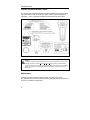
1
METROLOGIC INSTRUMENTS, INC.
®
MS9535 VoyagerBT Series
Single-Line Hand Held Laser Scanner
Installation and User's Guide
Copyright
© 2006 by Metrologic Instruments, Inc. All rights reserved. No part of this work
may be reproduced, transmitted, or stored in any form or by any means without
prior written consent, except by reviewer, who may quote brief passages in a
review, or provided for in the Copyright Act of 1976.
Trademarks
Metrologic is a registered trademark of Metrologic Instruments, Inc. Products
identified in this document are hereby acknowledged as trademarks, registered
or otherwise, of Metrologic Instruments, Inc. or their respective companies.
TABLE OF CONTENTS
Introduction
Product Overview ............................................................................................. 1
Scanner and Accessories ................................................................................. 2
Scanner Components ....................................................................................... 4
Receiver Cradle Components........................................................................... 5
Caution and Serial Number Labels ................................................................... 6
Maintenance ..................................................................................................... 6
Cradle Installation to the Host Device
RS232 and Light Pen........................................................................................ 7
Keyboard Wedge .............................................................................................. 8
Stand Alone Keyboard ...................................................................................... 9
IBM ................................................................................................................. 10
Low Speed USB ............................................................................................. 11
Full Speed USB (Powered by External Power Supply) ................................... 13
Full Speed USB (Powered by the Host Device).............................................. 14
Establishing Bluetooth Communication
Between the Scanner and the Cradle ............................................................. 15
Dynamic Pair Function.................................................................................... 15
When the MS9535 Acts as a Client to Other Bluetooth Devices..................... 16
When the MS9535 Acts as a Server to Other Bluetooth Devices ................... 17
The MI9535-5xx Receiver / Charger Cradle
Charging Guidelines and Low Battery Indicators ............................................ 18
Safety Precautions for Lithium Batteries ......................................................... 19
Communication Protocols ............................................................................... 20
Scanner Operation
Modes of Opteration ....................................................................................... 21
Auto-Trigger Mode .......................................................................................... 21
CodeGate Mode ............................................................................................. 21
RangeGate ..................................................................................................... 21
Inventory Mode ............................................................................................... 21
ii
TABLE OF CONTENTS
Indicators ........................................................................................................ 22
Audible..................................................................................................... 22
Visual....................................................................................................... 23
Failure Modes .......................................................................................... 25
Depth of Field by Bar Code Element Width .................................................... 26
IR Activation Range ........................................................................................ 27
Cable Removal ............................................................................................... 28
Cradle Wall Mount .......................................................................................... 28
Troubleshooting Guide ....................................................................................... 29
Design Specifications ......................................................................................... 33
Default Settings – Communication Parameters.................................................. 35
Upgrading the Flash ROM Firmware .................................................................. 40
Configuration Modes .......................................................................................... 40
Cradle and Cable Terminations
Cradle Pinout Connections ............................................................................. 41
Cable Connector Configurations..................................................................... 44
Regulatory Compliance ...................................................................................... 47
Safety.............................................................................................................. 47
EMC................................................................................................................ 48
Limited Warranty ................................................................................................ 50
Patents ............................................................................................................... 51
Index .................................................................................................................. 52
Contact Information and Office Locations........................................................... 54
iii
INTRODUCTION
MS9535 VoyagerBT® laser bar code scanner is a new member of Metrologic’s
Voyager series. Besides featuring the patented technologies of an automatic
trigger and CodeGate, the VoyagerBT has incorporated the latest Bluetooth®
wireless technology. This technology gives the customer the freedom of mobility,
with scanning up to 10 meters from the cradle.
VoyagerBT works hand in hand with its cradle. Before normal scanning, the
scanner must establish communications with the cradle by scanning a Bluetooth
address bar code. After communications have been established between the
scanner and cradle, future bar code scans will be transmitted from the scanner to
the cradle and from the cradle to the host. VoyagerBT scanners can also
optionally communicate to other Bluetooth enabled devices.
The cradle of the VoyagerBT also works as a battery charger for the scanner.
When resting in the cradle, the scanner can reach a fully charged state in 2.5
hours. When fully charged, the scanner can provide up to 12,000 scans. For
power saving, the scanner can be put into a full sleep mode by depressing the
CodeGate button for 5 seconds after the laser has shut down. In this mode, the
scanner can remain powered for up to 35 hours before the batteries require
recharging. To wake-up the scanner, simply depress the CodeGate button, and
the scanner will resume normal operation.
VoyagerBT includes the ability to decode Reduced Space Symbology (RSS) bar
codes. VoyagerBT offers checkout personnel the ability to scan bulky items
without the need for unnecessary heavy lifting by customers or checkout
personnel, making for added convenience. It can be used in applications
including supermarkets, hypermarkets, shopping clubs, retailers, light warehouse
and manufacturing.
1
INTRODUCTION
Scanner and Accessories
BASIC KIT
Part #
Description
MS9535-5
or
MS9535-5M
VoyagerBT Scanner
or
VoyagerBT Scanner with Memory
70-79004x
MS9535 VoyagerBT Wireless Hand Held Laser Scanner
Installation and User’s Guide*
00-02544x
MetroSelect Single-Line Configuration Guide*
70-73524
Wrist Strap
OPTIONAL ACCESSORIES
Part #
Description
Receiver / Charger Cradle
*
MI9535-514
Receiver / Charger Cradle, Full RS232
MI9535-541
Receiver / Charger Cradle, RS232/Light Pen
MI9535-547
Receiver / Charger Cradle, Keyboard Wedge
MI9535-538
Receiver / Charger Cradle, Low Speed USB,
Keyboard Emulation Mode or Serial Emulation Mode**
MI9535-511
Receiver / Charger Cradle, IBM
MI9535C540
Receiver / Charger Cradle,
Full Speed USB with External Power Supply
MI9535D540
Receiver / Charger Cradle,
Full Speed USB with Power from Register
Product manuals are available for download at www.metrologic.com.
** Configurable for Keyboard Emulation Mode or Serial Emulation Mode. The default
setting is Keyboard Emulation Mode.
Other items may be ordered for the specific protocol being used. To order additional items,
contact the dealer, distributor or call Metrologic’s Customer Service Department at
1-800-ID-METRO or 1-800-436-3876.
2
INTRODUCTION
Scanner and Accessories
OPTIONAL ACCESSORIES
Part #
Description
AC to DC Power Transformer- Regulated 5VDC @ 2A Output
46-46881
Power Supply, China
46-46880
Power Supply, United Kingdom
46-46879
Power Supply, Continental Europe
46-46882
Power Supply, Australia
46-46878
Power Supply, United States
46-46842
Power Supply, Japan
Communication Cable
54-54000x-N
RS232 / Light Pen Cable, short strain relief
54-54002x
Keyboard Wedge Cable, short strain relief
52-52828x
Low Speed USB Cable, short strain relief
54-54250x-N
IBM Cable, straight
54-54073x
Full Speed USB Cable, with Power From Register
54-54200x-N
Full Speed USB Cable, with External Power Supply
Other items may be ordered for the specific protocol being used. To order additional items,
contact the dealer, distributor or call Metrologic’s Customer Service Department at
1-800-ID-METRO or 1-800-436-3876.
3
INTRODUCTION
Scanner Components
Figure 1. Scanner Components
Item #
4
Description
1
Blue LED (see pages 23)
2
White LED (see pages 23)
3
Amber LED (see pages 23)
4
CodeGate Button
5
Output Window, Laser Aperture
6
Speaker (see page 22)
7
Wrist Strap
8
Charging Contacts /Rubber Feet
Do not short circuit the charging contacts on the scanner!
A short circuit can occur when a metallic object such as a coin,
clip or pen contacts the metal terminals of the scanner.
INTRODUCTION
Receiver/Charger Cradle Components
Figure 2 Cradle Components
Item #
Description
1
Recesses for Wall Mount Hardware
2
Power and Communication Connectors
3
Cable Strain Relief Channel
Charging Contacts
4
Do not short circuit the charging contacts on the scanner!
A short circuit can occur when a metallic object such as a coin,
clip or pen contacts the metal terminals of the scanner.
5
Bluetooth Address Bar Code (see page 23)
6
Wall Mount Hook – Scanner Support
7
Blue LED (see page 23)
8
Page Button
When the page button on the cradle is pressed, the scanner will
begin to beep and the blue and amber LEDs will alternately flash.
To discontinue paging the scanner, press the page button again.
5
INTRODUCTION
Caution and Serial Number Labels
The scanner and cradle have labels that provide important information including;
the model number, date of manufacture, serial number, safety and regulatory
information. Figure 3 provides examples of these labels and their locations.
Figure 3. Label Sample and Location
Caution:
To maintain compliance with applicable standards, all circuits connected to the scanner must
meet the requirements for SELV (Safety Extra Low Voltage) according to EN/IEC 60950-1.
To maintain compliance with standard CSA C22.2 No. 60950-1/UL 60950-1 and norm EN/IEC
60950-1, the power source should meet applicable performance requirements for a limited
power source.
Maintenance
Smudges and dirt can interfere with the proper scanning of a bar code.
The output window will need occasional cleaning with glass cleaner sprayed onto
a lint free, no-abrasive cleaning cloth.
6
CRADLE INSTALLATION TO THE HOST DEVICE
RS232 and Light Pen
1.
Turn off the host device.
2.
Connect the 10-pin RJ45 male
connector into the 10-pin modular
jack on the bottom of the cradle.
3.
Connect the 9-pin D-type Female
connector of the RS232 cable to the
proper COM port of the host device.
4.
Plug the external power supply into
the power jack on the bottom of the
cradle.
Check the AC input
requirements of the power
supply to make sure the
voltage matches the AC
outlet. The outlet must be
located near the
requirement and be easily
accessible.
5.
Plug the power supply into the AC
outlet. The blue LED on the rear of
the cradle will stay on.
6.
Turn on the host device.
7.
Establish communication between the scanner and cradle.
See page 15 for complete instructions on Establishing Bluetooth
Communication between the scanner and cradle.
Figure 4. RS232 and Light Pen
The scanner must be charged for a minimum of 3 hours before the
scanner can be placed in full operation for the first time. After the initial
preparation charge of 3 hrs, the battery will only require 2.5 hrs to come
to a full charge when it gives a Low Power warning (see page 18).
See page 6.
7
CRADLE INSTALLATION TO THE HOST DEVICE
Keyboard Wedge
1.
Turn off the host device.
2.
Connect the 10-pin RJ45 male
connector into the 10-pin modular
jack on the bottom of the cradle.
3.
Disconnect the keyboard from host.
4.
Connect the “Y” ends of the
communication cable to the
keyboard and keyboard port on the
host device. If necessary, use the
male/female adapter cable supplied
with the scanner for the proper
connections.
5.
Plug the external power supply into
the power jack on the bottom of the
cradle.
Check the AC input
requirements of the power
supply to make sure the
voltage matches the AC
outlet. The outlet must be
located near the
requirement and be easily
accessible.
Figure 5. Keyboard Wedge
6.
Plug the power supply into the AC outlet. The blue LED on the rear of the
cradle will stay on.
7.
Turn on the host device.
8.
Establish communication between the scanner and cradle.
See page 15 for complete instructions on Establishing Bluetooth
Communication between the scanner and cradle.
The scanner must be charged for a minimum of 3 hours before the
scanner can be placed in full operation for the first time. After the initial
preparation charge of 3 hrs, the battery will only require 2.5 hrs to come
to a full charge when it gives a Low Power warning (see page 18).
See page 6.
8
CRADLE INSTALLATION TO THE HOST DEVICE
Stand Alone Keyboard
1.
Turn off the host system.
2.
Connect the 10-pin RJ45 male
connector into the 10-pin modular
jack on the bottom of the cradle.
3.
Connect the 6-pin Mini-DIN male
connector of the keyboard cable to
keyboard port on the host device.
4.
Plug the external power supply into
the power jack on the bottom of the
cradle.
Check the AC input
requirements of the power
supply to make sure the
voltage matches the AC
outlet. The outlet must be
located near the requirement
and be easily accessible.
5.
Plug the power supply into the AC
outlet. The blue LED on the rear of
the cradle will stay on.
Figure 6. Stand Alone Keyboard
6.
Turn on the host device.
7.
Establish communication between the scanner and cradle.
See page 15 for complete instructions on Establishing Bluetooth
Communication between the scanner and cradle.
The scanner must be charged for a minimum of 3 hours before the
scanner can be placed in full operation for the first time. After the initial
preparation charge of 3 hrs, the battery will only require 2.5 hrs to come
to a full charge when it gives a Low Power warning (see page 18).
See page 6.
9
CRADLE INSTALLATION TO THE HOST DEVICE
IBM
1.
Turn off the host device.
2.
Connect the 10-pin RJ45 male
connector into the 10-pin modular
jack on the bottom of the cradle.
3.
Connect the IBM SDL connector to
the IBM port on the host device.
4.
Plug the power supply into the
power jack on the bottom of the
cradle.
Check the AC input
requirements of the power
supply to make sure the
voltage matches the AC
outlet. The outlet must be
located near the
requirement and be easily
accessible.
5.
Plug the power supply into the AC
outlet. The blue LED on the rear of
the cradle will stay on.
Figure 7. IBM
6.
Turn on the host device.
7.
Establish communication between the scanner and cradle.
See page 15 for complete instructions on Establishing Bluetooth
Communication between the scanner and cradle.
The scanner must be charged for a minimum of 3 hours before the
scanner can be placed in full operation for the first time. After the initial
preparation charge of 3 hrs, the battery will only require 2.5 hrs to come
to a full charge when it gives a Low Power warning (see page 18).
See page 6.
10
CRADLE INSTALLATION TO THE HOST DEVICE
Low Speed USB
Important Notes for VoyagerBT USB Interface Scanners
In order for the VoyagerBT to scan and charge properly both the power
supply and the USB communication cable must be attached before the host
device is turned on.
When the scanner is in the cradle and the power supply is connected to the
cradle, the scanner is in a charging state. The power supply acts as the
charging source not the USB communication cable. To perform normal
scanning operations, it is critical to connect the USB communication cable to
the cradle and the USB port on the host device. The blue LED on the cradle
will turn on when the USB communication cable is connected.
1.
Turn off the host device.
2.
Connect the USB B type connector
into the center jack on the bottom of
the charger cradle.
3.
Connect the USB A type connector
to the USB port on the host device.
The blue LED on the rear of the
cradle will turn on.
4.
Plug the power supply into the
power jack on the bottom of the
cradle.
Check the AC input
requirements of the power
supply to make sure the
voltage matches the AC
outlet. The outlet must be
located near the requirement
and be easily accessible.
5.
Figure 8. Low Speed USB
Plug the power supply into the AC outlet.
Installation instructions continued on page next page.
See page 6.
11
CRADLE INSTALLATION TO THE HOST DEVICE
Low Speed USB
6.
Turn on the host device.
7.
Establish communication between the scanner and cradle.
See page 15 for complete instructions on Establishing Bluetooth
Communication between the scanner and cradle.
As a default, the MI9535-538 leaves the factory with USB Keyboard
Emulation Mode enabled. Scan the following bar code to configure
the MI9535-538 for USB Serial Emulation Mode.
³
3
1
6
4
6
0
The scanner must be charged for a minimum of 3 hours before the
scanner can be placed in full operation for the first time. After the
initial preparation charge of 3 hrs, the battery will only require
2.5 hrs to come to a full charge when it gives a Low Power warning
(see page 18).
12
CRADLE INSTALLATION TO THE HOST DEVICE
Full Speed USB (Powered by External Power Supply)
1.
Turn off the host device.
2.
Connect the 10-pin RJ45 male
connector into the 10-pin
modular jack on the bottom of
the charger cradle.
3.
Connect the USB A type
connector to the USB port on
the host device.
4.
Plug the power supply into the
power jack on the bottom of the
cradle.
Check the AC input
requirements of the
power supply to make
sure the voltage matches
the AC outlet. The outlet
must be located near the
requirement and be
easily accessible.
Figure 9. Full Speed USB
5.
Plug the power supply into the AC outlet.
The blue LED on the rear of the cradle will stay on.
6.
Turn on the host device.
7.
Establish communication between the scanner and cradle. See page
15 for complete instructions on Establishing Bluetooth Communication
between the scanner and cradle.
The scanner must be charged for a minimum of 3 hours before the
scanner can be placed in full operation for the first time. After the initial
preparation charge of 3 hrs, the battery will only require 2.5 hrs to come
to a full charge when it gives a Low Power warning (see page 18).
See page 6.
13
CRADLE INSTALLATION TO THE HOST DEVICE
Full Speed USB (Powered by the Host Device)
1.
Turn off the host device.
2.
Connect the 10-pin RJ45 male
connector into the 10-pin
modular jack on the bottom of
the charger cradle.
3.
Connect the female DC power
jack of the USB cable to the
center power jack on the
bottom of the charger cradle.
4.
Connect the USB Type A plus
power connector to the USB
port on the host device.
5.
Turn on the host device.
6.
Establish communication
between the scanner and
cradle. See page 15 for
complete instructions on
Establishing Bluetooth
Communication between the
scanner and cradle.
Figure 10. Full Speed USB
The scanner must be charged for a minimum of 3 hours before the
scanner can be placed in full operation for the first time. After the initial
preparation charge of 3 hrs, the battery will only require 2.5 hrs to come
to a full charge when it gives a Low Power warning (see page 18).
See page 6.
14
ESTABLISHING BLUETOOTH COMMUNICATION
Between the Scanner and the Cradle
Bluetooth communication between the scanner and cradle must be
established before the VoyagerBT can be used for normal operation.
Dynamic Pair Function
Dynamic Pair Function refers to when a scanner has been paired or linked to a
specific cradle by scanning that cradle’s unique Bluetooth address code. The
unique address code is located directly on the body of the cradle, see figure
below. To established communication between the scanner and cradle:
1.
Scan the Bluetooth address code located
on the cradle.
2.
Wait 10 seconds.
3.
If successful, the blue LED on the cradle
and the blue LED on the scanner will stop
blinking and stay continuously illuminated.
Figure 11.
It is important to note that the MS9535 will only communicate with a cradle
whose Bluetooth address was the last address scanned. Once a cradle is paired
with the MS9535, another scanner can not be paired with that cradle until the
original connection is broken.
The following steps show how to change existing communication links between
two previously linked scanner/cradle pairs (#1 and #2).
1.
Place scanner #2 into sleep mode by holding down the CodeGate button
for three (3) seconds.
The existing communication links between scanner #2 and cradle
#2 are temporarily broken.
2.
Scan cradle #2’s Bluetooth address code with scanner #1.
The link between cradle #2 and scanner #2 is now permanently
broken.
3.
Scanner #1 has now re-established a communication link with cradle #2.
Any attempt to scan a cradle’s bluetooth code when it is already linked to
an active scanner, not in sleep mode, will result in the scanner razzing to
indicate a communication link is not possible due to existing links.
15
ESTABLISHING BLUETOOTH COMMUNICATION
When the MS9535 Acts as a Client to Other Bluetooth Devices
The MS9535 scanner can also link to other Bluetooth compatible devices such
as a desktop computer, laptop computer, or printer. As a default, the MS9535
will act as the client to another Bluetooth device. The devices’ Bluetooth address
must be scanned to establish a communication link between it and the MS9535
before they will work properly as a complete system. How the communication
link is established depends on the type of Bluetooth address bar code of the
compatible device.
a)
If the Bluetooth address is headed with FNC3 and consists of a 12-digit
3
hex value (e.g. 000CA7FFFF99), scan the address bar code to establish
the communication.
³
b)
0 0 0 C A 7 F F F F 9 9
Example Bluetooth Address with FNC3
If the Bluetooth address is NOT headed with FNC3 but is just a common
12-digit hex value (e.g. 000CA7000118), scan the Get Bluetooth Address
code first, and then scan the address bar code.
³
0
0
0 C A 7 F F F F F F
Get Bluetooth Address
0 0 0 C A 7 0 0 0 1 1 8
Example Bluetooth Address without FNC3
16
ESTABLISHING BLUETOOTH COMMUNICATION
When the MS9535 Acts as a Server to Other Bluetooth
Devices
Scan the Provide Service bar code below to enable the MS9535 to act as a
server and be detected by another Bluetooth device. This will allow other
Bluetooth devices to send inquiries to the scanner and attempt
communication. Use this bar code to establish communication directly with a
Bluetooth enabled device, bypassing the cradle.
³ 0 0 0 C A 7 0 0 0 0 0 0
Provide service to other Bluetooth devices
17
THE MI9535-5XX RECEIVER / CHARGER CRADLE
Charging Guidelines and Low Battery Indicators
The scanner should be fully charged prior to being placed into service. Metrologic
recommends that Bluetooth communication between the scanner and the cradle
be established first before charging.
To charge the scanner, place the unit into the cradle. The amber LED on the
scanner will begin to flash indicating the charging process has begun.
For first time installations, leave the scanner in the cradle for a full 3 hours.
Please note that the amber LED on the scanner will stop flashing after 2.5 hours
but it is recommended that the scanner be left in the cradle for an additional 30
minutes to complete the initial 3 hour charge.
Once the initial 3 hour charge is complete, the battery will only require 2.5 hours
to come to a full charge when the unit gives a low power warning. A steady
amber LED on the scanner will indicate the completion of a full charge.
Low Battery Warning
The following items indicate the scanner battery is low and will need to be
recharged.
z
During operation, the scanner gives two beeps after a successful scan.
z
The laser is not activated when a bar code is presented in the scanner’s
IR range and the scanner has automatically entered normal sleep mode
to reserve power.
z
The CodeGate button is pressed, the laser comes on briefly but does
not stay on and the scanner has automatically entered normal sleep
mode to reserve power.
z
The CodeGate button is pressed but the laser does not turn on.
Manufacturer’s Recommendation
If the scanner is not be used for a long period of time, it is recommended that the
unit be placed into normal or full sleep mode to save power.
z
To enable normal sleep mode, scan the configuration bar codes in the
MetroSelect Single-Line Configuration Guide (MLPN 00-02544x).
z
To enable full sleep mode, after the laser shuts off, depress the
CodeGate button and hold for 3 seconds, the scanner will give a long
beep and switch into full sleep mode.
To wake-up the scanner from either mode, depress the CodeGate button.
After an automatic reset, the scanner is ready for normal operation.
18
THE MI9535-5XX RECEIVER / CHARGER CRADLE
Safety Precautions for Lithium Batteries
• Do not place batteries in fire or heat the batteries.
• Do not store batteries near fire or other high temperature locations.
• Do not store or carry batteries together with metal objects.
• Do not expose batteries to water or allow the batteries to get wet.
• Do not connect (short) the positive and negative terminals, of the
batteries, to each other with any metal object.
• Do not pierce, strike or step on batteries or subject batteries to strong
impacts or shocks.
• Do not disassemble or modify batteries.
Caution:
Danger of explosion if batteries are incorrectly replaced. Replace only
with the same or equivalent type recommended by the manufacture.
Dispose of used batteries according to the recycle program for batteries
as directed by the governing agency for the country where the batteries
are to be discarded.
19
THE MI9535-5XX RECEIVER / CHARGER CRADLE
Communication Protocols
The MI9535-5xx cradle works as a receiver and a charger for the MS9535.
Receiver
Once Bluetooth communication has been established between the scanner and
cradle, the cradle will act as a receiver for the barcode data transmitted from the
scanner. The cradle then transmitts the data to the host. Metrologic provides
several versions of the cradle to meet a variety of host interfaces. The following
chart lists all available cradle versions and their default communication protocol.
Cradle
Version
Identifier
(xx)
Communication Protocol(s)
14
Full RS232
41
RS232 / Light Pen Emulation
47
Receiver / Charger Cradle, Keyboard Wedge
38
Low Speed USB
Keyboard Emulation Mode or Serial Emulation Mode**
11
IBM and RS232 Transmit / Receive
MI9535C5
40
Full Speed USB with external Power Supply
MI9535D5
40
Full Speed USB with power from Register
MI9535-5
** Configurable for Keyboard Emulation Mode or Serial Emulation Mode.
The default setting is Keyboard Emulation Mode.
Charger
As a charger, the cradle recharges the scanner whenever it is set into place.
Even if the scanner’s battery is full, the cradle will continue to supply power to the
scanner. To order a cradle with charging capabilities only (MLPN 46-46772),
contact a Metrologic Customer service representative at 1-800-ID-METRO or
1-800-436-3876.
20
SCANNER OPERATION
Modes of Operation
Auto-Trigger Mode
z
Auto Trigger, In-Stand
z
Auto-triggers while in the stand
z
Bar code is automatically decoded and transmitted
CodeGate Mode
z
CodeGate, Out-of-Stand
z
CodeGate activates when removed from the stand
z
Bar code data is transmitted when the button is pressed
RangeGate
The operation range of Bluetooth communication is 10 meters between the
scanner and receiver/cradle. When the scanner is out of Bluetooth operation
range, the communication link with the cradle will break and the blue LED will
start to flash on the scanner. At which time, RangeGate will become active and
the bar codes scanned, while out of Bluetooth range, will be stored in the SRAM
of the scanner instead of being lost. Once communication is re-established, the
stored data will be transmitted to the receiver/cradle and then to the host device.
For the bar codes associated with this mode, please consult the MetroSelect
Single-Line Configuration Guide (MLPN 00-02544x).
Inventory Mode (Specific to MS9535-5M)
For light warehousing applications, Metrologic offers the MS9535-5M VoyagerBT
with extended memory and a unique feature called Inventory Mode. This mode
allows a customer to store approximately 2500 bar codes (length dependent)
with quantity information to facilitate inventory taking. This information can then
be transmitted in batch to the host by scanning a specific bar code or putting the
unit back into the cradle. For the bar codes associated with this mode, please
consult the MetroSelect Single-Line Configuration Guide (MLPN 00-02544x).
21
SCANNER OPERATION
Indicators
Audible
When the scanner is in operation, it provides audible feedback. These sounds
indicate the status of the scanner. Eight settings are available for the tone of the
beeper (normal, 6 alternate tones and no tone). To change the tones, refer to
the MetroSelect Single-Line Configuration Guide (MLPN 00-02544x) or
MetroSet2’s help files.
One Beep
The scanner will beep once after communication has been
established and the unit is properly placed into the cradle.
When the scanner successfully reads a bar code, the scanner’s white
LED will flash and the unit will beep once.
When the CodeGate button is pressed for 3 seconds, the scanner will
indicate it has entered full sleep mode with a extended beep.
Two Beeps
When the scanner has a low battery voltage, it will emit two beeps
after a successful scan and flash the amber LED every 5 seconds.
When there is a Flash ROM upgrade needed, the scanner will beep
twice followed by alternating flashing of the blue and white LEDs.
When communication has been broken between the scanner and
cradle, the scanner will emit two combined high and low tones while
the blue LED flashes.
Three Beeps
When entering configuration mode, the white LED will flash while the
scanner simultaneously beeps three times.
When exiting configuration mode, the scanner will beep three times
and the white LED will stop flashing.
When using single-code-Configuration, the scanner will sound a
3-combination tone (a short pause followed by a high tone and a low
tone). This indicates a single configuration bar code has successfully
configured the scanner.
When scanning a Bluetooth address bar code, the scanner will beep
three times. The scanner’s blue LED will start to flash as it attempts to
establish a communication link. The scanner will emit a 3-combination
tone and the blue LED will stop flashing, staying steadily illuminated
to indicate communication between the scanner and the cradle has
been successfully established.
Razzberry Tones
This tone indicates a type of failure. Refer to “Failure Modes" on
page 25.
22
SCANNER OPERATION
Indicators
Visual
The MS9535 has three LED indicators (blue, white and amber) located on the
head of the scanner. When the scanner is in operation, the flashing or stationary
activity of the LEDs indicates the status of the scanner and the current scan.
Blue, White & Amber LEDs are off
The scanner is not receiving power from the cradle or the scanner’s
internal battery.
The scanner is in full sleep mode. Press the CodeGate button to
wake the scanner from full sleep mode. The blue LED will start to
flash as the unit exits full sleep mode.
Steady Amber
After establishing communication, when the scanner is put into the
cradle and the battery has been fully charged, the amber LED will
remain steady.
If the communication is not established, when the scanner is put into
the cradle, the amber LED will stay on after a short delay.
Steady Blue
When the laser is active, the blue LED is illuminated. The blue LED
will remain illuminated until the laser is deactivated.
Steady Blue and Single White Flash
When the scanner successfully reads a bar code, the white LED will
flash, the blue LED remains steady and the scanner will beep once.
If the scanner reads the bar code successfully at a relatively long
distance but still within the 10-meter operation range, the white LED
may flash after a short delay.
Steady Blue and Steady White
After a successful scan, the scanner transmits the data to the cradle.
If the cradle is not ready to accept the information, the scanner’s
white LED will remain on until the data can be transmitted or until a
communication time-out occurs.
23
SCANNER OPERATION
Indicators
Visual
Alternating Flashing of Blue and White
This indicates the scanner is in configuration mode. Two razzberry
tones indicate that an invalid bar code has been scanned while in this
mode.
If the scanner is in RangeGate active mode, this indicates the SRAM
of the scanner becomes full.
If the scanner needs to have a Flash ROM upgrade, the alternating
flashing of the blue and white LEDs will occur during startup and is
accompanied by three beeps.
Steady White, Blue off
This indicates the laser is off and the scanner is still waiting for
communication from the cradle.
Flashing Blue
The blue LED on the scanner and the cradle indicates the
“connecting” status of the cradle with the scanner. When the
Bluetooth connection breaks, the blue LED will flash. This indicates
the scanner is trying to establish communication with the cradle.
A single blue flash on the cradle indicates data has been received
from the scanner.
Flashing Amber
When scanner is in the cradle, a flashing amber LED indicates the
scanner is being charged.
When the scanner is out of cradle, a flashing amber LED indicates the
scanner has low battery power and needs recharging.
24
SCANNER OPERATION
Indicators
Failure Modes
Flashing Blue and one Razzberry Tone
This indicates the scanner has experienced a laser sub-system
failure. Return the unit for repair to an authorized service center.
Flashing Blue and White with Two Razzberry Tones
This indicates the scanner has experienced a scanning mechanism
failure. Return the unit for repair to an authorized service center.
Continuous Razzberry Tone with all LEDs off
If the scanner emits a continuous razzberry tone upon power-up, the
scanner has experienced an electronic failure. Return the unit for
repair to an authorized service center.
Three Beeps – on power up
If the scanner beeps 3 times on power-up then the non-volatile
memory (NovRAM) that holds the scanner configuration has failed. If
the scanner does not respond after reconfiguring, return the scanner
for repair to an authorized service center.
Two Razzberry Tones with Steady White
When the scanner scans a bar code without establishing Bluetooth
communication first, the scanner will emit two razzberry tones and the
white LED will stay steadily lit.
The scanner reads a bar code but the cradle fails to transmit the data
Long Beeps with Steady Amber LED
The scanner will emit a long beep every 5 second indicating the
scanner's contacts are not making a physical connection with the
charging contacts on the cradle.
Proper placement of the scanner in the cradle is essential for the
charging process. .
25
SCANNER OPERATION
Depth of Field by Bar Code Element Width*
Minimum Bar Code Element Width
A
B
C
D
E
F
G
H
J
K
mm
.13
.15
-
-
.19
-
.25
.33
.53
-
mils
5.2
5.7
-
-
7.5
-
10
13
21
-
Figure 12. Depth of Field by Bar Code Element Width
* All specifications are subject to change without notice.
26
SCANNER OPERATION
IR Activation Range
Figure 13. IR Activation Range
* All specifications are subject to change without notice.
27
SCANNER OPERATION
Cable Removal
Before removing the cable from the scanner, Metrologic recommends that the
power on the host device is off and the power supply has been disconnected
from the PowerLink cable
1.
Locate the small ‘pinhole’ on the bottom of the
cradle near the cable.
2.
Bend an ordinary
paperclip into the shape
shown above.
3.
Insert the paperclip (or
the small metallic pin)
into the small ‘pin-hole’.
Figure 14. Cable Release
4.
You will hear a faint ‘click’. Pull gently on the strain-relief of the 10-pin,
RJ45 cable to remove the cable from the cradle.
Cradle Wall Mount
z
Metrologic provides
two #7 wood screws for
securing the cradle
to the wall.
z
Figure 15 provides the
pilot hole dimensions
for securing the cradle
base.
Figure 15. Hole Pattern
z
Install the
cradle base
to the wall.
Figure 16. Wall Attachment (left) and Wall Hook (right)
28
TROUBLESHOOTING GUIDE
The following guide is for reference purposes only. Contact a Metrologic
representative at 1-800-ID-Metro or 1-800-436-3876 to preserve the limited
warranty terms.
Symptoms
Possible Causes
Solution
The scanner
has no LEDs,
beeper or laser
while seated in
cradle.
No power is being
supplied from cradle
to scanner.
Check the transformer, outlet and
power strip. Verify the power
cable is plugged into the cradle
properly.
The scanner
has no LEDs,
beeper or laser
when out of the
cradle.
The scanner’s
internal battery is not
supplying power to
scanner.
Place the scanner into the cradle
to recharge the battery.
The scanner
locks up after
the first scan.
The white LED
stays on and
the unit razzes
twice.
Communication has
not been established
between scanner and
cradle.
Establish communication between
scanner and cradle before
scanning a normal bar code.
The scanner
locks up after
scanning a bar
code. The
white LED stays
on and the unit
razzes twice.
The distance between
scanner and cradle is
beyond the 10-meter
operation range and
RangeGate is not
activated.
Bring the scanner back into the
10-meter communication range
from the cradle.
The scanner
emits 2 beeps
with alternately
flashing LEDs
on power-up.
There may be a
possible ROM failure.
A flash ROM upgrade required.
29
TROUBLESHOOTING GUIDE
Symptoms
Possible Causes
Solution
The scanner
emits 3 beeps
on power up.
A non-volatile RAM
failure may have
occurred.
Contact a Metrologic customer
service representative, if the unit
will not hold the configuration.
The scanner
emits a
continuous razz
tone on power –
up.
A RAM or ROM
failure may have
occurred.
Contact a Metrologic customer
service representative.
The scanner
emits a razz tone
There has been a
and the blue LED
VLD failure.
flashes on power
up.
Contact a Metrologic customer
service representative.
The scanner
emits a razz tone
A scanning
and both the blue
mechanism failure
and white LEDs
may have occurred.
flash at powerup.
Contact a Metrologic customer
service representative.
The scanner
The same symbol
scans,
timeout is set too
communicates
short.
and beeps twice.
Adjust the same symbol timeout
for a longer time.
The scanner
powers up, but
does not scan
and/or beep
30
The beeper disabled
and/or no tone is
selected
Enable beeper and/or select a
tone.
The bar code being
scanned is a
particular symbology
that is not enabled.
UPC/EAN, Code 39, interleaved 2
of 5, Code 93, Code 128 and
Codabar are enabled by default.
Verify that the type of bar code
being read has been selected.
The bar code being
scanned does not
satisfy the scanner’s
configured criteria
(i.e. character length
lock, or a minimum
length)
Verify that the bar code that is
being scanned falls into the
criteria.
Typical of Non-UPC/EAN codes,
the scanner defaults to a minimum
of 3-character bar code.
TROUBLESHOOTING GUIDE
Symptoms
Possible Causes
Solution
The scanner
scans a bar
code, but locks
up after the first
scan. The white
LED stays on.
The scanner is
configured to support
some form of host
handshaking but is
not receiving the
signal.
If the scanner is setup to support
ACK/NAK, RTS/CTS, XON/XOFF
or D/E, verify that the host cable
and host are supporting the
handshaking properly.
The scanner
scans, but the
data transmitted
to the host is
incorrect.
The scanner’s data
format does not
match the host
system requirements.
Verify that the scanner’s data
format matches that required by
the host. Most sure that the
scanner is connected to the
proper host port.
The scanner
beeps at some
The print quality of
bar codes and
the bar code is
NOT for others
suspect.
of the same bar
code symbology.
The aspect ratio of
the bar code is out of
tolerance.
Scanner beeps
at some bar
codes and NOT
for others of the
same bar code
symbology
Characters are
being dropped.
The bar code may
have been printed
incorrectly.
Check the print mode. The type of
printer could be the problem.
Change the print settings (i.e.
change to econo mode or high
speed).
Check print mode. The type of
printer could be the problem.
Change print settings. i.e. change
to econo mode or high speed.
The scanner is not
configured correctly
for this type of bar
code.
Check if it is a check
digit/character/or border problem
in the configuration of the
scanner.
The minimum symbol
length setting does
not work with the bar
code.
Check if the correct minimum
symbol length is set.
Inter-character delay
needs to be added to
the transmitted output
Add some inter-character delay to
the transmitted output
31
TROUBLESHOOTING GUIDE
Symptoms
Possible Causes
Solution
The scanner
scans the bar
code but there
is no data.
Make sure the scanner is
configured for the appropriate
mode.
The scanner
scans but the
data is not
correct.
Make sure that the proper PC type
AT, PS2 or XT is selected. Verify
correct country code and data
formatting are selected. Adjust
inter-character delay symptom.
The scanner
configuration is not
correctly.
Increase the interscan code delay
setting. Adjust whether the F0
break is transmitted. It may be
necessary to try this in both
settings.
The scanner is
transmitting
each character
twice.
Alpha
characters show
as lower case
characters.
The computer is in
Caps Lock mode.
Enable the Caps Lock detect
setting of the scanner to detect
whether the PC is operating in
Caps Lock.
Everything
works except for
a couple of
characters.
These characters
may not be supported
by that country’s key
look up table.
Try operating the scanner in Alt
mode.
Com port at the host
is not working or
configured properly
Check to make sure that the baud
rate, parity of the scanner, and the
communication port match. Check
to make sure the configuration is
looking for RS232 data.
The cable is not
connected to the
proper com port.
Check to make sure the
communication cable is securely
connected to the host and cradle
and that the cable is connected to
the correct com port on the host.
The cradle and host
may not be
configured for the
same interface
parameters.
Check that the cradle and the host
are configured for the same
interface parameters
The scanner
powers-up OK
and scans OK
but does not
communicate
properly with
the host.
The host is
receiving data
but the data
does not look
correct.
32
DESIGN SPECIFICATIONS
Scanner and Cradle Specifications
Operational
Light Source:
Visible Laser Diode 650 nm ± 10 nm
Laser Power:
0.96 mW (peak)
Depth of Scan Field:
Scan Speed:
Scan Pattern:
Minimum Bar Width:
0 mm – 203 mm (0” – 8”)
0.330 mm (13 mil) bar code at default setting
72 ± 2 scan lines per second
Single scan line
0.127 mm (5.0 mil)
Decode Capability:
Autodiscriminates all standard 1D bar codes,
for other symbologies call a Metrologic service representative.
System Interfaces:
RS232/Light Pen, PC Keyboard Wedge, Stand-Alone
Keyboard, Low Speed USB, Full Speed USB, IBM
Print Contrast:
Number of Characters
Read:
Roll, Pitch, Yaw:
Beeper Operation:
Scanner LED Indicators:
Cradle LED indicators:
35% minimum reflectance difference
Up to 80 data characters
(Maximum number will vary based on symbology & density)
42°, 68°, 52°
7 tones or no beep
Blue
laser on, ready to scan
White
good read
Amber
battery full
Blue
connection status
Mechanical
Length:
198 mm (7.8”)
Width:
Handle - 45 mm (1.8”), Head - 78 mm (3.1”)
Depth:
40 mm (1.6”)
Weight:
Scanner: 199 g (7.02 oz)
Cradle: 225g (7.94 oz)
* All specifications are subject to change without notice.
33
DESIGN SPECIFICATIONS
Scanner and Cradle Specifications
Electrical
Input Voltage:
Cradle Power:
Scanner Power:
Scanner Current:
Cradle Current:
DC Transformers:
Battery Capacity
/Recharge Time:
Radio Range:
Scanner:
5.2VDC ± 0.25V
Cradle:
5.0VDC ± 0.25V
0.6 W
Operating
1.15 W
Sleep
150 mW
Operating
230 mA@5VDC
Sleep
30mA@ 5VDC
Cradle: 120 mA @ 5VDC
Class II; 5.0V @ 2A
12000 scans per charge / recharge time = 2.5 hours
10 m (33 ft)
For regulatory compliance information, see pages 47 - 49.
Environmental
Operating = 0°C to 40° (32° to 104°F)
Temperature:
Storage = -20°C to 50°C (-4°F to 122°F)
Humidity:
Light Levels:
Shock:
Contaminants:
Ventilation:
5% to 95% relative humidity, non-condensing
Up to 4842 Lux (450 footcandles)
Designed to withstand 1.5 m (5’) drops
Sealed to resist airborne particulate contaminants
None required
* All specifications are subject to change without notice.
34
DEFAULT SETTINGS - COMMUNICATION PARAMETERS
Many functions of the scanner and cradle can be “configured” – that is, enabled
or disabled. The scanner and cradle are shipped from the factory configured to a
set of default conditions. The default parameter has an asterisk (*) in the charts
on the following pages. If an asterisk is not in the default column then the default
setting is OFF or DISABLED. Every communication does not support every
parameter. If the communication supports a parameter listed in the charts on the
following pages, a check mark will appear.
Parameter
Default
RS232
Light
Pen
IBM
46XX
KBW
USB
9
9
9
9
9
Continuous Scan Mode
9
9
9
9
9
Blinky Scan
9
9
9
9
9
Continuous Blinky Scan
9
9
9
9
9
Custom (one shot) Scan
9
9
9
9
9
9
9
9
9
9
9
9
9
9
9
Normal Scan Mode
Long-Range In-Stand
*
*
Short-Range In-Stand
9
9
9
9
9
Short-Range Out-of-Stand
9
9
9
9
9
CodeGate Active In-Stand
9
9
9
9
9
Long-Range Out-of-Stand
*
CodeGate Inactive In-Stand
*
9
9
9
9
9
CodeGate Active Out-of Stand
*
9
9
9
9
9
9
9
9
9
9
CodeGate Inactive Out-of Stand
UPC/EAN
*
9
9
9
9
9
Code 128
*
9
9
9
9
9
Code 93
*
9
9
9
9
9
Codabar
*
9
9
9
9
9
Interleaved 2 of 5 (ITF)
*
9
9
9
9
9
MOD 10 check on ITF
9
9
9
9
9
Code 11
9
9
9
9
9
9
9
9
9
9
9
9
9
9
9
Code 39
Full ASCII Code 39
*
35
DEFAULT SETTINGS - COMMUNICATION PARAMETERS
RS232
Light
Pen
IBM
46XX
KBW
USB
Mod 43 Check on Code 39
9
9
9
9
9
MSI-Plessey 10/10 Check Digit
9
9
9
9
9
9
9
9
9
9
9
9
9
9
9
Variable
9
9
9
9
9
3
9
9
9
9
9
None
9
9
9
9
9
Parameter
MSI-Plessey Mod 10 Check Digit
Default
*
Paraf Support ITF
ITF Symbol Lengths
Minimum Symbol Length
Symbol Length Lock
9
9
Spaces High as Code 39
9
9
Bars High as Scanned
9
9
Spaces High as Scanned
9
9
Poll light pen source
9
Bars High as Code 39
*
Beeper tone
Normal
9
9
9
9
9
Beep/transmit sequence
Before
transmit
9
9
9
9
9
Communication timeout
None
9
9
9
9
9
Razzberry tone on timeout
9
9
9
9
9
Three beeps on timeout
9
9
9
9
9
9
9
9
9
9
9
9
9
9
9
9
9
9
9
9
9
9
9
9
9
9
9
9
9
9
9
9
9
9
9
Same symbol rescan timeout:
1000 msecs
9
9
9
9
9
No Same symbol timeout
9
9
9
9
9
Same symbol rescan timeout
250 msecs
Same symbol rescan timeout
375 msecs
Same symbol rescan timeout:
500 msecs)
Same symbol rescan timeout
625 msecs
Same symbol rescan timeout
750 msecs
Same symbol rescan timeout
875 msecs
36
*
DEFAULT SETTINGS - COMMUNICATION PARAMETERS
Parameter
Default
RS232
Light
Pen
IBM
46XX
KBW
USB
9
9
9
9
9
1 msecs
10 msecs
in KBW
9
9
9
9
9
Number of scan buffers (maximum)
4
9
9
9
9
9
Transmit UPC-A check digit
*
9
9
9
9
9
Transmit UPC-E check digit
9
9
9
9
9
Expand UPC-E
9
9
9
9
9
Convert UPC-A to EAN-13
9
9
9
9
9
Transmit lead zero on UPC-E
9
9
9
9
9
Infinite Same symbol timeout
Inter-character delay
Configurable in 1 msec steps
(max 255 msecs)
Transmit UPC-A number system
*
9
9
9
9
9
Transmit UPC-A Manufacturer
ID#
*
9
9
9
9
9
Transmit UPC – A Item ID#
*
9
9
9
9
9
Transmit Codabar Start/Stop
Characters
9
9
9
9
CLSI Editing (Enable)
9
9
9
9
Transmit Mod 43 Check digit on
Code 39
9
9
9
9
Transit Mod 10/ITF
9
9
9
9
Transmit MSI-Plessy
9
9
9
9
Scanner:
Space
Cradle: None
9
9
Baud Rate
9600
9
8 Data Bits
Scanner: *
9
7 Data Bits
Cradle: *
9
2
9
Parity
Stop Bits
Transmit Sanyo ID Characters
9
9
9
Nixdorf ID
9
9
9
LRC Enabled
9
9
9
37
DEFAULT SETTINGS - COMMUNICATION PARAMETERS
Parameter
Default
RS232
Light
Pen
IBM
46XX
KBW
USB
UPC Prefix
9
9
9
UPC Suffix
9
9
9
Carriage Return
*
9
9
9
Line Feed-Disabled by default in
KBW
*
9
9
9
Tab Prefix
9
9
9
Tab Suffix
9
9
9
“DE” Disable Command
9
“FL” Laser
9
Enable Command
9
DTR Handshaking support
9
RTS/CTS Handshaking
9
Character
*
9
Message RTS/CTS
9
XON/XOFF Handshaking
9
ACK/NAK
9
Two Digit Supplements
9
Five Digit Supplements
9
Bookland
9
977 (2 digit) Supplemental
Requirement
9
as
code 39
as
code 39
as
code 39
9
9
9
9
9
9
9
9
9
9
Supplements are not Required
*
9
9
9
9
9
Two Digit Redundancy
*
9
9
9
9
9
9
9
9
9
9
9
9
9
9
9
9
as
code
39
9
9
9
9
9
9
Five digit Redundancy
100 msec to Find Supplement
Configurable in 100 msec steps
(max 800 msec)
*
Coupon Code 128
† Configurable Code Lengths
38
7 avail
9
DEFAULT SETTINGS - COMMUNICATION PARAMETERS
Default
RS232
Light
Pen
IBM
46XX
KBW
USB
† Code Selects with
Configurable Code Length
Locks
3 avail
9
9
9
9
9
Configurable Prefix characters
10 avail
9
9
9
Suffix characters
10 avail
9
9
9
Prefixes for Individual Code
types
9
9
9
Editing
9
9
9
Parameter
Inter Scan-Code delay
Configurable
(100 µsec steps)
9
9
9
800 µsec
Function/control Key Support
Minimum Element width
Configurable in 5.6 µsec steps
9
9
1 msec
RangeGate Enabled
9
9
9
9
9
Authenticate
9
9
9
9
9
MTLG Challenge
9
9
9
9
9
9
9
9
9
9
Charging enabled
*
† These options are mutually exclusive. One can not be used in conjunction with the other.
39
UPGRADING THE FLASH ROM FIRMWARE
The MetroSet 2 program also allows the user of a Metrologic scanner to quickly
upgrade to a new or custom version of software. It requires the use of a personal
computer running under Windows 95 or greater and the use of a communication
port. The user merely connects the scanner’s cradle to a communication port on
the PC, launches the MetroSet 2 program, and blasts off to new software
upgrades.
Each MS9535 and its cradle, regardless of the version number or communication
protocol, can be upgraded. In other words, all RS232/Light Pen (-41),
keyboard wedge (-47), Low Speed USB (-38), Full Speed USB (C40), Full Speed
USB (D40), and IBM 468X/469X (-11) units can be upgraded. To upgrade all
units, an RS232 cable (MLPN 54-54000B-N) is required. Communication between
the scanner and the cradle must be established before upgrading the flash ROM
within the scanner.
The upgrades and custom software versions will be supplied by Metrologic in
files called Motorola S-record files. These files contain all the information needed
to upgrade the scanner. Simply add this file to the working directory or retrieve
the file from its current location.
The program guides the user with a simplistic one click approach. The user must
first select the file. Once selected and verified, the file is ready to be used in the
upgrade. Press the button to start the upgrading. Contact a Metrologic customer
service representative for additional details on upgrading flash ROM firmware.
CONFIGURATION MODES
The MS9535 VoyagerBT has 3 configuration modes.
Bar Codes
VoyagerBT can be configured by scanning the bar codes in the MetroSelect
Single-Line Configuration Guide (MLPN 00-02544x). Please refer to this
guide for instructions. The MetroSelect Single-Line Configuration Guide can
be downloaded for FREE from Metrologic’s website (www.metrologic.com).
MetroSet2
This user-friendly Windows-based configuration program allows you to
simply ‘point-and-click’ at the desired scanner options. This program can be
downloaded for FREE from Metrologic’s website (www.metrologic.com), or
set-up disks can be ordered by calling 1-800-ID-METRO.
Serial Program Mode
This method is only valid when RS232 cradles are used. It basically
simulates the scanning of the configuration bar codes, but through the serial
port. Serial Program Mode is described in detail in the MetroSelect SingleLine Configuration Guide (MLPN 00-02544x).
40
CRADLE AND CABLE TERMINATIONS
Cradle Pinout Connections
There are interface and power ports located on the bottom of each MI9535-5xx
cradle. The number of ports and type of connection varies by cradle model and
the interface required. The following charts provide the pinout information for the
different cradle models and interfaces available.
MI9535-514 Full RS232 and
MI9535-541
RS232 / Light Pen Emulation
Figure 17.
Pin
1
2
3
4
5
6
7
8
9
10
MI9535-547
Keyboard Wedge
10-Pin, RJ45
Function
Ground
RS232 Transmit Output
RS232 Receive Input
PC Data
PC Clock
KB Clock
PC +5V
KB Data
+5VDC
Shield Ground
10-Pin, RJ45
Pin
Function
1
Ground
2
RS232 Transmit Output
3
RS232 Receive Input
4
RTS Output
5
CTS Input
6
DTR Input / LTPN Source*
7
Reserved
8
LTPN Data*
9
Reserved
10
Shield Ground
* MI9535-541 Interface Specific
Pin
1
2
3
4
5
6
7
8
9
10
MI9535-511
IBM
10-Pin, RJ45
Function
Ground
RS232 Transmit Output
RS232 Receive Input
RTS Output
CTS Input
DTR Input
IBM B- Transmit
IBM A+ Receive
Reserved
Shield Ground
41
CRADLE AND CABLE TERMINATIONS
Cradle Pinout Connections
MI9535-538
Low Speed USB Port
10-Pin, RJ45
Pin
Function
1
Ground
2
RS232 Transmit Output
3
RS232 Receive Input
4
RTS Output
5
CTS Input
6
Reserved
7
Reserved
8
Reserved
9
Reserved
10
Shield Ground
USB Type B
Function
Pin
1
VCC
2
D3
D+
4
Ground
Figure 18. Cradle MI9535-538
Pin
1
2
3
4
5
6
7
8
9
10
Figure 19. Cradle MI9535D540
42
MI9535D540
Full Speed USB
10-Pin, RJ45
Function
Ground
RS232 Transmit Output
RS232 Receive Input
RTS Output
CTS Input
D+
USB +5V
DReserved
Shield Ground
CRADLE AND CABLE TERMINATIONS
Cradle Pinout Connections
Pin
1
2
3
4
5
6
7
8
9
10
MI9535C540
Full Speed USB
10-Pin, RJ45
Function
Ground
RS232 Transmit Output
RS232 Receive Input
RTS Output
CTS Input
D+
USB +5V
DReserved
Shield Ground
Figure 20. Cradle MI9535C540
43
CRADLE AND CABLE TERMINATIONS
Cable Connector Configurations (Host End)
RS232/Light Pen Cable
MLPN 54-54000x-N
Pin
Function
1
Shield Ground
2
RS232 Transmit Output
3
RS232 Receive Input
4
DTR Input/Light Pen Source
5
Power/Signal Ground
6
Light Pen Data
7
CTS Input
8
RTS Output
9
+5VDC
9-Pin D-Type Connector
USB Cable
52-52828x
MLPN
Pin
1
2
3
4
Function
VCC
DD+
Ground
IBM Cable
MLPN
Pin
1
2
3
4
44
54-54250x-N
Function
Ground
IBM A+
IBM BReserved
SDL A Key
CRADLE AND CABLE TERMINATIONS
Cable Connector Configurations
Full Speed USB Cable with power
from Register
MLPN
Pin
1
2
3
4
5
6
7
8
54-54073x
Function
+5VDC
DD+
Ground
Ground
+12V
+12V
Ground
USB A Plus Power
Type Connector
Full Speed USB Cable
with external Power Supply
MLPN 54-54200x-N
Pin
1
2
3
+5VDC
DD+
Function
4
Ground
USB A Plus Power
Type Connector
45
CRADLE AND CABLE TERMINATIONS
Cable Connector Configurations
Keyboard Wedge PowerLink Cable
54-54002x -3
Pin
1
2
3
4
5
Pin
1
2
3
4
5
6
Function
Keyboard Clock
Keyboard Data
No Connect
Power Ground
+5 Volts DC
Function
PC Data
No Connect
Power Ground
+5 Volts DC
PC Clock
No Connect
5-Pin DIN, Female
6-Pin DIN, Male
Metrologic will supply an adapter cable with a 5-pin DIN male connector on one
end and a 6-pin mini DIN female connector on the other. According to the
termination required, connect the appropriate end of the adapter cable to the
PowerLink cable, leaving the necessary termination exposed for connecting to
the keyboard and the keyboard port on the PC.
Keyboard Wedge Adapter Cable
Pin
Function
1
PC Clock
2
PC Data
3
No Connect
4
Power Ground
5
+5 Volts DC
Pin
46
5-Pin DIN, Male
Function
1
Keyboard Data
2
No Connect
3
Power Ground
4
+5 Volts DC
5
Keyboard Clock
6
No Connect
6-pin Mini DIN, Female
REGULATORY COMPLIANCE
Safety
ITE Equipment
IEC 60950-1, EN 60950-1
Laser
Laser Class 1: IEC 60825-1:1993+A1+A2,
EN 60825-1:1994+A1+A2
Caution
Use of controls or adjustments or performance of procedures other than those specified
herein may result in hazardous laser light exposure. Under no circumstances should
the customer attempt to service the laser scanner. Never attempt to look at the laser
beam, even if the scanner appears to be nonfunctional. Never open the scanner in an
attempt to look into the device. Doing so could result in hazardous laser light exposure.
The use of optical instruments with the laser equipment will increase eye hazard.
Atención
La modificación de los procedimientos, o la utilización de controles o ajustes distintos
de los especificados aquí, pueden provocar una luz de láser peligrosa. Bajo ninguna
circunstancia el usuario deberá realizar el mantenimiento del láser del escáner. Ni
intentar mirar al haz del láser incluso cuando este no esté operativo. Tampoco deberá
abrir el escáner para examinar el aparato. El hacerlo puede conllevar una exposición
peligrosa a la luz de láser. El uso de instrumentos ópticos con el equipo láser puede
incrementar el riesgo para la vista.
Attention
L'emploi de commandes, réglages ou procédés autres que ceux décrits ici peut
entraîner de graves irradiations. Le client ne doit en aucun cas essayer d'entretenir luimême le scanner ou le laser. Ne regardez jamais directement le rayon laser, même si
vous croyez que le scanner est inactif. N'ouvrez jamais le scanner pour regarder dans
l'appareil. Ce faisant, vous vous exposez à une rayonnement laser qú êst hazardous.
L'emploi d'appareils optiques avec cet équipement laser augmente le risque
d'endommagement de la vision.
Achtung
Die Verwendung anderer als der hier beschriebenen Steuerungen, Einstellungen oder
Verfahren kann eine gefährliche Laserstrahlung hervorrufen. Der Kunde sollte unter
keinen Umständen versuchen, den Laser-Scanner selbst zu warten. Sehen Sie niemals
in den Laserstrahl, selbst wenn Sie glauben, daß der Scanner nicht aktiv ist. Öffnen Sie
niemals den Scanner, um in das Gerät hineinzusehen. Wenn Sie dies tun, können Sie
sich einer gefährlichen Laserstrahlung aussetzen. Der Einsatz optischer Geräte mit
dieser Laserausrüstung erhöht das Risiko einer Sehschädigung.
Attenzione
L’utilizzo di sistemi di controllo, di regolazioni o di procedimenti diversi da quelli descritti
nel presente Manuale può provocare delle esposizioni a raggi laser rischiose. Il cliente
non deve assolutamente tentare di riparare egli stesso lo scanner laser. Non guardate
mai il raggio laser, anche se credete che lo scanner non sia attivo. Non aprite mai lo
scanner per guardare dentro l’apparecchio. Facendolo potete esporVi ad una
esposizione laser rischiosa. L’uso di apparecchi ottici, equipaggiati con raggi laser,
aumenta il rischio di danni alla vista..
47
REGULATORY COMPLIANCE
EMC
Emissions
FCC Part 15, ICES-003, CISPR 22, EN 55022, EN300 328 V1.6.1,
EN301 489-17 V1.2.1
Immunity
CISPR 24, EN 55024
Changes or modifications not expressly approved by the party responsible for
compliance could void the user’s authority to operate the equipment.
Class A Devices
This equipment has been tested and found to comply with limits for a Class A digital device,
pursuant to part 15 of the FCC Rules. These limits are designed to provide reasonable protection
against harmful interference when the equipment is operated in a commercial environment. This
equipment generates, uses and can radiate radio frequency energy and, if not installed and used
in accordance with the instruction manual, may cause harmful interference to radio
communications. Operation of this equipment in a residential area is likely to cause harmful
interference, in which case the user will be required to correct the interference at their own
expense. Any unauthorized changes or modifications to this equipment could void the user’s
authority to operate this device.
This device complies with part 15 of the FCC Rules. Operation is subject to the following two
conditions: (1) This device may not cause harmful interference, and (2) this device must accept
any interference received, including interference that may cause undesired operation.
The radiated output power of this intentional wireless radio is far below the FCC radio frequency
exposure limits. The internal wireless radio operates within guidelines found in radio frequency
safety standards and recommendations, which reflect the consensus of the scientific community.
The level of energy omitted is far less than the electromagnetic energy emitted by wireless devices
such as mobile phones. However, the use of wireless radios may be restricted in some situations
or environments, such as aboard airplanes. If you are unsure of restrictions, you are encouraged
to ask for authorization before turning on the wireless radio.
Notice
This Class A digital apparatus complies with Canadian ICES-003*.
* The IC before the certification /registration number signifies that the Industry Canada technical specifications were met.
Remarque
Cet appareil numérique de classe A est conforme à la norme canadienne NMB-003.
European Standard
Warning
This is a class A product. In a domestic environment this product may cause radio interference
in which case the user may be required to take adequate measures.
Funkstöreigenschaften nach EN55022:1998
Warnung!
Dies ist eine Einrichtung der Klasse A. Diese Einrichtung kann im Wohnbereich Funkstörungen
verursachen. In diesem Fall kann vom Betreiber verlangt werden, angemessene Massnahmen
durchzuführen.
Standard Europeo
Attenzione
Questo e’ un prodotto di classe A. Se usato in vicinanza di residenze private potrebbe causare
interferenze radio che potrebbero richiedere all’utilizzatore opportune misure.
Attention
Ce produit est de classe “A”. Dans un environnement domestique, ce produit peut être la cause
d’interférences radio. Dans ce cas l’utiliseteur peut être amené à predre les measures
adéquates.
48
REGULATORY COMPLIANCE
EMC
Changes or modifications not expressly approved by the party responsible for
compliance could void the user’s authority to operate the equipment.
Class B Devices
This device complies with Part 15 of the FCC Rules. Operation is subject to the following two
conditions: (1) This device may not cause harmful interference, and (2) this device must accept
any interference received, including interference that may cause undesired operation.
This equipment has been tested and found to comply with the limits for a Class B digital device,
pursuant to Part 15 of the FCC rules. These limits are designed to provide reasonable protection
against harmful interference in a residential installation. This equipment generates, uses and can
radiate radio frequency energy and, if not installed and used in accordance with the instructions,
may cause harmful interference to radio communications. However, there is no guarantee that
interference will not occur in a particular installation. If this equipment does cause harmful
interference to radio or television reception, which can be determined by turning the equipment off
and on, the user is encouraged to try to correct the interference by one or more of the following
measures:
• Reorient or relocate the receiving antenna
• Increase the separation between the equipment and receiver
• Connect the equipment into an outlet on a circuit different from that to which the receiver
is connected
• Consult the dealer or an experienced radio/TV technician for help
Notice
This Class B digital apparatus complies with Canadian ICES-003*.
* The IC before the certification /registration number signifies that the Industry Canada technical specifications were met.
Remarque
Cet appareil numérique de classe B est conforme à la norme canadienne NMB-003.
49
LIMITED WARRANTY
®
The MS9535 VoyagerBT scanners are manufactured by Metrologic at its Blackwood, New
Jersey, U.S.A facility and its Suzhou, China facility. The MS9535 VoyagerBT scanners
have a two (2) year limited warranty from the date of manufacture. Metrologic warrants and
represents that all MS9535 VoyagerBT scanners are free of all defects in material,
workmanship and design, and have been produced and labeled in compliance with all
applicable U.S. Federal, state and local laws, regulations and ordinances pertaining to their
production and labeling.
This warranty is limited to repair, replacement of product or refund of product price at the
sole discretion of Metrologic. Faulty equipment must be returned to one of the following
Metrologic repair facilities: Blackwood, New Jersey, USA; Madrid, Spain; or Suzhou, China.
To do this, contact the appropriate Metrologic Customer Service/Repair Department to
obtain a Returned Material Authorization (RMA) number.
In the event that it is determined the equipment failure is covered under this warranty, Metrologic
shall, at its sole option, repair the Product or replace the Product with a functionally equivalent unit
and return such repaired or replaced Product without charge for service or return freight, whether
distributor, dealer/reseller, or retail consumer, or refund an amount equal to the original purchase
price.
This limited warranty does not extend to any Product which, in the sole judgment of Metrologic,
has been subjected to abuse, misuse, neglect, improper installation, or accident, nor any damage
due to use or misuse produced from integration of the Product into any mechanical, electrical or
computer system. The warranty is void if the case of Product is opened by anyone other than
Metrologic’s repair department or authorized repair centers.
THIS LIMITED WARRANTY, EXCEPT AS TO TITLE, IS IN LIEU OF ALL OTHER WARRANTIES
OR GUARANTEES, EITHER EXPRESS OR IMPLIED, AND SPECIFICALLY EXCLUDES,
WITHOUT LIMITATION, WARRANTIES OF MERCHANTABILITY AND FITNESS FOR A
PARTICULAR PURPOSE UNDER THE UNIFORM COMMERCIAL CODE, OR ARISING OUT OF
CUSTOM OR CONDUCT. THE RIGHTS AND REMEDIES PROVIDED HEREIN ARE
EXCLUSIVE AND IN LIEU OF ANY OTHER RIGHTS OR REMEDIES. IN NO EVENT SHALL
METROLOGIC BE LIABLE FOR ANY INDIRECT OR CONSEQUENTIAL DAMAGES,
INCIDENTAL DAMAGES, DAMAGES TO PERSON OR PROPERTY, OR EFFECT ON
BUSINESS OR PROPERTY, OR OTHER DAMAGES OR EXPENSES DUE DIRECTLY OR
INDIRECTLY TO THE PRODUCT, EXCEPT AS STATED IN THIS WARRANTY. IN NO EVENT
SHALL ANY LIABILITY OF METROLOGIC EXCEED THE ACTUAL AMOUNT PAID TO
METROLOGIC FOR THE PRODUCT. METROLOGIC RESERVES THE RIGHT TO MAKE ANY
CHANGES TO THE PRODUCT DESCRIBED HEREIN.
CORPORATE HEADQUARTERS,
NORTH AMERICA
METROLOGIC EUROPEAN REPAIR CENTER
(MERC)
Metrologic Instruments, Inc.
90 Coles Rd.
Blackwood, NJ 08012-4683
Customer Service Department
Tel: 1-800-ID-METRO
Fax: 856-228-6673
Email: [email protected]
Metrologic Eria Ibérica, SL
C/Alfonso Gomez, 38-40, 1D
28037 Madrid
Tel: +34 913 751 249
Fax: +34 913 270 437
MTLG AUTO ID INSTRUMENTS (SHANGHAI) CO., LTD
Suzhou Sales Office
BLK A, Room# 03/03-04
No.5 Xinghan Street, Xinsu Industrial Square
China-Singapore Suahou Industrial Park, Suzhou, PRC
Tel: 86-512-67622550
Fax: 86-512-67622560
Email: [email protected]
50
PATENTS
This METROLOGIC product may be covered by, but is not limited to, one or
more of the following U.S. Patents:
US Patent No.
4,958,984; 5,081,342; 5,260,553; 5,340,971; 5,340,973; 5,424,525; 5,468,951;
5,484,992; 5,525,789; 5,528,024; 5,591,953; 5,616,908; 5,627,359; 5,661,292;
5,777,315; 5,789,730; 5,789,731; 5,811,780; 5,825,012; 5,828,048; 5,883,375;
5,886,337; 5,895,907; 5,925,870; 5,925,871; 5,939,698; 6,029,894; D408,532;
No license right or sublicense is granted, either expressly or by implication,
estoppel, or otherwise, under any METROLOGIC or third party intellectual
property rights (whether or not such third party rights are licensed to
METROLOGIC), including any third party patent listed above, except for an
implied license only for the normal intended use of the specific equipment,
circuits, and devices represented by or contained in the METROLOGIC products
that are physically transferred to the user, and only to the extent of
METROLOGIC’s license rights and subject to any conditions, covenants and
restrictions therein.
Other worldwide patents are currently pending.
51
INDEX
A
H
AC .................................. see power
accessories ...............................2, 3
address bar code......... 5, 15, 16, 17
amber LED ..................see indicator
authenticate.................................39
host ............................................. 24
B
battery ................. 18, 19, 20, 33, 34
beep ............................see indicator
blue LED......................see indicator
Bluetooth communication .......5, 15,
16, 17, 21
button ................ 4, 5, 15, 18, 19, 21
C
cable
communication............... 3, 24, 40
removal ....................................28
caution...............................6, 19, 47
charger ........................... see cradle
check digit ...................................36
client ......................................16, 17
CodeGate ........ 4, 15, 18, 19, 21, 35
communication ................ 20, 35–39
compliance ........................ 6, 47–49
configuration................................22
connector...............................41–46
cradle................. 2, 5, 15, 17–21, 40
current .........................................34
customer service .........................50
D
DC .................................. see power
default settings ......................35–39
depth of field................................26
E
EMC ......................................48, 49
EMI ..............................................48
emissions ....................................48
I
IBM .............................see interface
immunity...................................... 48
indicator .............. 22–25, 29, 30, 31
audible.... 4, 5, 18, 19, 22, 29, 30,
31, 33
failure....................... 4, 25, 29, 30
visual ............ 4, 5, 15, 18, 19, 21,
23–24, 29, 30, 33
interface .......................... 33, 35–39
default settings .................. 35–39
IBM .................... 2, 10, 20, 35–39
Keyboard Wedge........ 2, 3, 8, 20,
35–39
Light Pen ............. 2, 7, 20, 35–39
RS232 ................. 2, 7, 20, 35–39
Stand-Alone Keyboard 2, 3, 9, 20
USB .............. 2, 3, 11, 12, 13, 14,
20, 35–39
inventory ..................................... 21
IR ................................................ 27
K
Keyboard Wedge ........see interface
L
laser ............................................ 47
LED............................. see indicator
light levels ................................... 33
Light Pen.....................see interface
light source.................................. 33
M
manual .......................................... 2
memory ....................................... 21
MetroSet2 ................................... 40
modes ............................. 21, 35, 40
P
F
flash.............................................40
52
parameter.............................. 35–39
patent .......................................... 51
INDEX
pin-hole........................................28
pinout ....................................41–46
power..................... 3, 18, 19, 33, 34
R
range ................... 21, 26, 27, 34, 35
RangeGate ............................21, 39
razzberry tone .............see indicator
receiver........................... see cradle
repair ...........................................25
RMA ............................................50
RS232 ........................ see interface
S
safety................................. 6, 19, 47
serial number.................................6
server ..........................................17
sleep mode..................................18
stand ...........................................35
Stand-Alone Keyboard see interface
suppliment ...................................38
symbol .........................................36
T
tone............................. see indicator
transformer......................see power
troubleshooting ..................... 29–32
U
upgrade....................................... 40
USB ............................see interface
V
ventilation........................ 18, 34, 36
voltage ........................................ 34
W
warranty ...................................... 50
weight ......................................... 33
white LED.................... see indicator
window...................................... 4, 6
53
54
November 2006 Version 01
Printed in the USA
7 0 -7 9 0 0 4 F