1
User Guide for Furnace 3.1 for Autodesk Media & Entertainment Systems
2nd December 2008
VISUAL EFFECTS SOFTWARE
ii
The Foundry VISUAL EFFECTS SOFTWARE
2008 The Foundry Visionmongers Ltd. All rights reserved.
User Guide for Furnace 3.1 for Autodesk Media & Entertainment Systems
This manual, as well as the software described in it, is furnished under license and may only be used or copied in
accordance with the terms of such license. This manual is provided for informational use only and is subject to change
without notice. The Foundry assumes no responsibility or liability for any errors or inaccuracies that may appear in
this book.
No part of this manual may be reproduced, stored in a retrieval system, or transmitted in any form without the prior
written permission of The Foundry.
The Foundry logo is a trademark of The Foundry. Autodesk, Autodesk Media and Entertainment, Discreet, Flame, Flint,
Fire Inferno and Smoke are either registered trademarks or trademarks of Autodesk, Inc./Autodesk Canada Inc. in the
USA and/or other countries. All other brand names, product names, or trademarks belong to their respective holders.
The Foundry algorithms use the FFTW library developed by Matteo Frigo and Steven G. Johnson, copyright 2003 Matteo
Frigo, copyright 2003 Massachusetts Institute of Technology. All rights reserved. Used under terms of a commercial
license. http://www.fftw.org.
Software engineering Simon Robinson, Ralph McEntagart, Phil Parsonage.
Algorithms Dr. Bill Collis, Dr. Anil Kokaram of Trinity College Dublin.
Product testing Jack Binks, Jonathan Barson
Writing and layout design Jonathan Barson, Ralph McEntagart and Dr. Bill Collis using LATEX.
Proof reading Jack Binks and Jonathan Barson.
VISUAL EFFECTS SOFTWARE
Contents
iii
Contents
Introduction
16
About this User Guide . . . . . . . . . . . . . . . . . . . . . . . . . . . . . . . . .
16
Notation . . . . . . . . . . . . . . . . . . . . . . . . . . . . . . . . . . . . . . . .
16
Example Images . . . . . . . . . . . . . . . . . . . . . . . . . . . . . . . . . . . .
16
Installing Furnace on Discreet Irix . . . . . . . . . . . . . . . . . . . . . . . . . .
16
Installing Furnace on Discreet Linux . . . . . . . . . . . . . . . . . . . . . . . . .
17
Installing Furnace on Burn . . . . . . . . . . . . . . . . . . . . . . . . . . . . . .
17
Licensing Furnace . . . . . . . . . . . . . . . . . . . . . . . . . . . . . . . . . . .
18
Removing Furnace from Irix . . . . . . . . . . . . . . . . . . . . . . . . . . . . . .
19
Documentation . . . . . . . . . . . . . . . . . . . . . . . . . . . . . . . . . . . . .
19
Network Rendering . . . . . . . . . . . . . . . . . . . . . . . . . . . . . . . . . .
19
About Furnace Plug-ins . . . . . . . . . . . . . . . . . . . . . . . . . . . . . . . .
20
Other Foundry Products . . . . . . . . . . . . . . . . . . . . . . . . . . . . . . . .
20
Basics
21
What is a Spark? . . . . . . . . . . . . . . . . . . . . . . . . . . . . . . . . . . . .
21
Where are the Sparks? . . . . . . . . . . . . . . . . . . . . . . . . . . . . . . . .
21
Loading Sparks . . . . . . . . . . . . . . . . . . . . . . . . . . . . . . . . . . . . .
21
Using Sparks . . . . . . . . . . . . . . . . . . . . . . . . . . . . . . . . . . . . . .
22
Command and Module Modes . . . . . . . . . . . . . . . . . . . . . . . . . . . . .
22
Saving Sparks . . . . . . . . . . . . . . . . . . . . . . . . . . . . . . . . . . . . . .
22
Common Controls
23
Display Tools . . . . . . . . . . . . . . . . . . . . . . . . . . . . . . . . . . . . . .
23
Help . . . . . . . . . . . . . . . . . . . . . . . . . . . . . . . . . . . . . . . . . . .
24
Tooltips . . . . . . . . . . . . . . . . . . . . . . . . . . . . . . . . . . . . . . . . .
24
Process . . . . . . . . . . . . . . . . . . . . . . . . . . . . . . . . . . . . . . . . .
24
Reset . . . . . . . . . . . . . . . . . . . . . . . . . . . . . . . . . . . . . . . . . .
24
Roto/Matte Tool . . . . . . . . . . . . . . . . . . . . . . . . . . . . . . . . . . . .
25
The Roto Tool . . . . . . . . . . . . . . . . . . . . . . . . . . . . . . . . . .
25
Roto Parameters . . . . . . . . . . . . . . . . . . . . . . . . . . . . . . . . .
31
The Foundry
Furnace
Contents
iv
Crops . . . . . . . . . . . . . . . . . . . . . . . . . . . . . . . . . . . . . . . . . .
33
Box . . . . . . . . . . . . . . . . . . . . . . . . . . . . . . . . . . . . . . . . . . .
35
Align
36
Introduction . . . . . . . . . . . . . . . . . . . . . . . . . . . . . . . . . . . . . .
36
Quick Start . . . . . . . . . . . . . . . . . . . . . . . . . . . . . . . . . . . . . . .
37
Inputs . . . . . . . . . . . . . . . . . . . . . . . . . . . . . . . . . . . . . . . . . .
37
Parameters . . . . . . . . . . . . . . . . . . . . . . . . . . . . . . . . . . . . . . .
37
Align . . . . . . . . . . . . . . . . . . . . . . . . . . . . . . . . . . . . . . .
37
Roto/Mask . . . . . . . . . . . . . . . . . . . . . . . . . . . . . . . . . . . .
40
DataOut . . . . . . . . . . . . . . . . . . . . . . . . . . . . . . . . . . . . . .
40
Crops . . . . . . . . . . . . . . . . . . . . . . . . . . . . . . . . . . . . . . .
40
Examples . . . . . . . . . . . . . . . . . . . . . . . . . . . . . . . . . . . . . . . .
40
Clean Area Alignment . . . . . . . . . . . . . . . . . . . . . . . . . . . . . .
40
MatchMoving . . . . . . . . . . . . . . . . . . . . . . . . . . . . . . . . . . .
43
Stabilisation . . . . . . . . . . . . . . . . . . . . . . . . . . . . . . . . . . .
44
BlockTexture
47
Introduction . . . . . . . . . . . . . . . . . . . . . . . . . . . . . . . . . . . . . .
47
Quick Start . . . . . . . . . . . . . . . . . . . . . . . . . . . . . . . . . . . . . . .
47
Crowds . . . . . . . . . . . . . . . . . . . . . . . . . . . . . . . . . . . . . .
49
Inputs . . . . . . . . . . . . . . . . . . . . . . . . . . . . . . . . . . . . . . . . . .
50
Parameters . . . . . . . . . . . . . . . . . . . . . . . . . . . . . . . . . . . . . . .
50
Texture . . . . . . . . . . . . . . . . . . . . . . . . . . . . . . . . . . . . . .
50
Roto/Matte . . . . . . . . . . . . . . . . . . . . . . . . . . . . . . . . . . . .
51
Examples . . . . . . . . . . . . . . . . . . . . . . . . . . . . . . . . . . . . . . . .
51
ChannelRepair
52
Introduction . . . . . . . . . . . . . . . . . . . . . . . . . . . . . . . . . . . . . .
52
Quick Start . . . . . . . . . . . . . . . . . . . . . . . . . . . . . . . . . . . . . . .
53
Inputs . . . . . . . . . . . . . . . . . . . . . . . . . . . . . . . . . . . . . . . . . .
54
Parameters . . . . . . . . . . . . . . . . . . . . . . . . . . . . . . . . . . . . . . .
54
Repair . . . . . . . . . . . . . . . . . . . . . . . . . . . . . . . . . . . . . . .
54
Roto/Matte . . . . . . . . . . . . . . . . . . . . . . . . . . . . . . . . . . . .
55
Furnace
The Foundry
Contents
v
Crops . . . . . . . . . . . . . . . . . . . . . . . . . . . . . . . . . . . . . . .
ColourAlign
55
56
Introduction . . . . . . . . . . . . . . . . . . . . . . . . . . . . . . . . . . . . . .
56
Quick Start . . . . . . . . . . . . . . . . . . . . . . . . . . . . . . . . . . . . . . .
56
Inputs . . . . . . . . . . . . . . . . . . . . . . . . . . . . . . . . . . . . . . . . . .
57
Parameters . . . . . . . . . . . . . . . . . . . . . . . . . . . . . . . . . . . . . . .
57
Crops . . . . . . . . . . . . . . . . . . . . . . . . . . . . . . . . . . . . . . .
58
Examples . . . . . . . . . . . . . . . . . . . . . . . . . . . . . . . . . . . . . . . .
58
BelleColourAlign . . . . . . . . . . . . . . . . . . . . . . . . . . . . . . . . .
58
ColourMatte
60
Introduction . . . . . . . . . . . . . . . . . . . . . . . . . . . . . . . . . . . . . .
60
Quick Start . . . . . . . . . . . . . . . . . . . . . . . . . . . . . . . . . . . . . . .
61
Inputs . . . . . . . . . . . . . . . . . . . . . . . . . . . . . . . . . . . . . . . . . .
62
Parameters . . . . . . . . . . . . . . . . . . . . . . . . . . . . . . . . . . . . . . .
62
Crops . . . . . . . . . . . . . . . . . . . . . . . . . . . . . . . . . . . . . . .
64
Examples . . . . . . . . . . . . . . . . . . . . . . . . . . . . . . . . . . . . . . . .
64
Belle . . . . . . . . . . . . . . . . . . . . . . . . . . . . . . . . . . . . . . . .
64
Correlate
67
Introduction . . . . . . . . . . . . . . . . . . . . . . . . . . . . . . . . . . . . . .
67
Quick Start . . . . . . . . . . . . . . . . . . . . . . . . . . . . . . . . . . . . . . .
67
Inputs . . . . . . . . . . . . . . . . . . . . . . . . . . . . . . . . . . . . . . . . . .
68
Parameters . . . . . . . . . . . . . . . . . . . . . . . . . . . . . . . . . . . . . . .
68
Align . . . . . . . . . . . . . . . . . . . . . . . . . . . . . . . . . . . . . . .
69
Roto/Mask . . . . . . . . . . . . . . . . . . . . . . . . . . . . . . . . . . . .
72
Data Out . . . . . . . . . . . . . . . . . . . . . . . . . . . . . . . . . . . . .
72
Crops/Comp . . . . . . . . . . . . . . . . . . . . . . . . . . . . . . . . . . .
72
Examples . . . . . . . . . . . . . . . . . . . . . . . . . . . . . . . . . . . . . . . .
72
Belle . . . . . . . . . . . . . . . . . . . . . . . . . . . . . . . . . . . . . . . .
72
The Foundry
Furnace
Contents
vi
DeBlur
76
Introduction . . . . . . . . . . . . . . . . . . . . . . . . . . . . . . . . . . . . . .
76
Quick Start . . . . . . . . . . . . . . . . . . . . . . . . . . . . . . . . . . . . . . .
76
Inputs . . . . . . . . . . . . . . . . . . . . . . . . . . . . . . . . . . . . . . . . . .
77
Parameters . . . . . . . . . . . . . . . . . . . . . . . . . . . . . . . . . . . . . . .
77
DeBlur . . . . . . . . . . . . . . . . . . . . . . . . . . . . . . . . . . . . . . .
78
Examples . . . . . . . . . . . . . . . . . . . . . . . . . . . . . . . . . . . . . . . .
79
LibertyBlurred . . . . . . . . . . . . . . . . . . . . . . . . . . . . . . . . . .
79
Fruit . . . . . . . . . . . . . . . . . . . . . . . . . . . . . . . . . . . . . . . .
81
DeFlicker
84
Introduction . . . . . . . . . . . . . . . . . . . . . . . . . . . . . . . . . . . . . .
84
Quick Start . . . . . . . . . . . . . . . . . . . . . . . . . . . . . . . . . . . . . . .
84
Tuning . . . . . . . . . . . . . . . . . . . . . . . . . . . . . . . . . . . . . .
85
Copying Flicker . . . . . . . . . . . . . . . . . . . . . . . . . . . . . . . . . .
86
Warning! . . . . . . . . . . . . . . . . . . . . . . . . . . . . . . . . . . . . .
86
Inputs . . . . . . . . . . . . . . . . . . . . . . . . . . . . . . . . . . . . . . . . . .
86
Parameters . . . . . . . . . . . . . . . . . . . . . . . . . . . . . . . . . . . . . . .
86
Flicker
. . . . . . . . . . . . . . . . . . . . . . . . . . . . . . . . . . . . . .
86
Examples . . . . . . . . . . . . . . . . . . . . . . . . . . . . . . . . . . . . . . . .
88
Hedge . . . . . . . . . . . . . . . . . . . . . . . . . . . . . . . . . . . . . . .
88
Bus . . . . . . . . . . . . . . . . . . . . . . . . . . . . . . . . . . . . . . . .
89
Bike . . . . . . . . . . . . . . . . . . . . . . . . . . . . . . . . . . . . . . . .
90
DeGrain
92
Introduction . . . . . . . . . . . . . . . . . . . . . . . . . . . . . . . . . . . . . .
92
Quick Start . . . . . . . . . . . . . . . . . . . . . . . . . . . . . . . . . . . . . . .
92
Working Interactively . . . . . . . . . . . . . . . . . . . . . . . . . . . . . .
93
Spatial Tuning . . . . . . . . . . . . . . . . . . . . . . . . . . . . . . . . . .
94
Temporal Tuning . . . . . . . . . . . . . . . . . . . . . . . . . . . . . . . . .
94
Inputs . . . . . . . . . . . . . . . . . . . . . . . . . . . . . . . . . . . . . . . . . .
94
Parameters . . . . . . . . . . . . . . . . . . . . . . . . . . . . . . . . . . . . . . .
94
DeGrain . . . . . . . . . . . . . . . . . . . . . . . . . . . . . . . . . . . . . .
95
Furnace
The Foundry
Contents
vii
Analysis . . . . . . . . . . . . . . . . . . . . . . . . . . . . . . . . . . . . . .
96
Roto/Matte . . . . . . . . . . . . . . . . . . . . . . . . . . . . . . . . . . . .
96
Examples . . . . . . . . . . . . . . . . . . . . . . . . . . . . . . . . . . . . . . . .
96
DeNoise
98
Introduction . . . . . . . . . . . . . . . . . . . . . . . . . . . . . . . . . . . . . .
98
Quick Start . . . . . . . . . . . . . . . . . . . . . . . . . . . . . . . . . . . . . . .
98
Inputs . . . . . . . . . . . . . . . . . . . . . . . . . . . . . . . . . . . . . . . . . .
99
Parameters . . . . . . . . . . . . . . . . . . . . . . . . . . . . . . . . . . . . . . .
99
DeNoise . . . . . . . . . . . . . . . . . . . . . . . . . . . . . . . . . . . . . .
99
Examples . . . . . . . . . . . . . . . . . . . . . . . . . . . . . . . . . . . . . . . .
99
Mike . . . . . . . . . . . . . . . . . . . . . . . . . . . . . . . . . . . . . . . . 100
Depth
103
Introduction . . . . . . . . . . . . . . . . . . . . . . . . . . . . . . . . . . . . . . 103
Quick Start . . . . . . . . . . . . . . . . . . . . . . . . . . . . . . . . . . . . . . . 103
Inputs
. . . . . . . . . . . . . . . . . . . . . . . . . . . . . . . . . . . . . . . . . 104
Parameters . . . . . . . . . . . . . . . . . . . . . . . . . . . . . . . . . . . . . . . 104
Roto/Mask . . . . . . . . . . . . . . . . . . . . . . . . . . . . . . . . . . . . 104
Examples . . . . . . . . . . . . . . . . . . . . . . . . . . . . . . . . . . . . . . . . 104
Leicester Square . . . . . . . . . . . . . . . . . . . . . . . . . . . . . . . . . 104
DirtRemoval
107
Introduction . . . . . . . . . . . . . . . . . . . . . . . . . . . . . . . . . . . . . . 107
Quick Start . . . . . . . . . . . . . . . . . . . . . . . . . . . . . . . . . . . . . . . 108
Inputs . . . . . . . . . . . . . . . . . . . . . . . . . . . . . . . . . . . . . . . . . . 109
Parameters . . . . . . . . . . . . . . . . . . . . . . . . . . . . . . . . . . . . . . . 109
Dirt . . . . . . . . . . . . . . . . . . . . . . . . . . . . . . . . . . . . . . . . 109
Crops . . . . . . . . . . . . . . . . . . . . . . . . . . . . . . . . . . . . . . . 112
Examples . . . . . . . . . . . . . . . . . . . . . . . . . . . . . . . . . . . . . . . . 112
Roller blades . . . . . . . . . . . . . . . . . . . . . . . . . . . . . . . . . . . 112
The Foundry
Furnace
Contents
viii
EdgeMatte
114
Introduction . . . . . . . . . . . . . . . . . . . . . . . . . . . . . . . . . . . . . . 114
Quick Start . . . . . . . . . . . . . . . . . . . . . . . . . . . . . . . . . . . . . . . 115
Inputs . . . . . . . . . . . . . . . . . . . . . . . . . . . . . . . . . . . . . . . . . . 116
Parameters . . . . . . . . . . . . . . . . . . . . . . . . . . . . . . . . . . . . . . . 116
EdgeMatte . . . . . . . . . . . . . . . . . . . . . . . . . . . . . . . . . . . . 116
Examples . . . . . . . . . . . . . . . . . . . . . . . . . . . . . . . . . . . . . . . . 119
Mike . . . . . . . . . . . . . . . . . . . . . . . . . . . . . . . . . . . . . . . . 119
Kronos
122
Introduction . . . . . . . . . . . . . . . . . . . . . . . . . . . . . . . . . . . . . . 122
Quick Start . . . . . . . . . . . . . . . . . . . . . . . . . . . . . . . . . . . . . . . 122
Speed . . . . . . . . . . . . . . . . . . . . . . . . . . . . . . . . . . . . . . . 122
Frames . . . . . . . . . . . . . . . . . . . . . . . . . . . . . . . . . . . . . . 123
Fine Tuning
. . . . . . . . . . . . . . . . . . . . . . . . . . . . . . . . . . . . . . 123
Separating Foreground and Background Motions . . . . . . . . . . . . . . . 124
Flicker . . . . . . . . . . . . . . . . . . . . . . . . . . . . . . . . . . . . . . . 124
Noise . . . . . . . . . . . . . . . . . . . . . . . . . . . . . . . . . . . . . . . 124
Motion Blur . . . . . . . . . . . . . . . . . . . . . . . . . . . . . . . . . . . . . . . 125
Inputs . . . . . . . . . . . . . . . . . . . . . . . . . . . . . . . . . . . . . . . . . . 125
Parameters . . . . . . . . . . . . . . . . . . . . . . . . . . . . . . . . . . . . . . . 125
Kronos . . . . . . . . . . . . . . . . . . . . . . . . . . . . . . . . . . . . . . 125
Crops . . . . . . . . . . . . . . . . . . . . . . . . . . . . . . . . . . . . . . . 129
Calculator . . . . . . . . . . . . . . . . . . . . . . . . . . . . . . . . . . . . . 129
Examples . . . . . . . . . . . . . . . . . . . . . . . . . . . . . . . . . . . . . . . . 129
Taxi Retiming. . . . . . . . . . . . . . . . . . . . . . . . . . . . . . . . . . . 129
Taxi Motion Blur. . . . . . . . . . . . . . . . . . . . . . . . . . . . . . . . . . 131
Kronos Algorithm . . . . . . . . . . . . . . . . . . . . . . . . . . . . . . . . 131
MatchGrade
132
Introduction . . . . . . . . . . . . . . . . . . . . . . . . . . . . . . . . . . . . . . 132
Quick Start . . . . . . . . . . . . . . . . . . . . . . . . . . . . . . . . . . . . . . . 132
Inputs . . . . . . . . . . . . . . . . . . . . . . . . . . . . . . . . . . . . . . . . . . 133
Furnace
The Foundry
Contents
ix
Parameters . . . . . . . . . . . . . . . . . . . . . . . . . . . . . . . . . . . . . . . 133
Examples . . . . . . . . . . . . . . . . . . . . . . . . . . . . . . . . . . . . . . . . 133
Mike . . . . . . . . . . . . . . . . . . . . . . . . . . . . . . . . . . . . . . . . 133
MatteToRoto
135
Introduction . . . . . . . . . . . . . . . . . . . . . . . . . . . . . . . . . . . . . . 135
Quick Start . . . . . . . . . . . . . . . . . . . . . . . . . . . . . . . . . . . . . . . 135
Inputs . . . . . . . . . . . . . . . . . . . . . . . . . . . . . . . . . . . . . . . . . . 135
Parameters . . . . . . . . . . . . . . . . . . . . . . . . . . . . . . . . . . . . . . . 135
Examples . . . . . . . . . . . . . . . . . . . . . . . . . . . . . . . . . . . . . . . . 136
BelleWalking . . . . . . . . . . . . . . . . . . . . . . . . . . . . . . . . . . . 136
MotionBlur
138
Introduction . . . . . . . . . . . . . . . . . . . . . . . . . . . . . . . . . . . . . . 138
Quick Start . . . . . . . . . . . . . . . . . . . . . . . . . . . . . . . . . . . . . . . 138
Inputs
. . . . . . . . . . . . . . . . . . . . . . . . . . . . . . . . . . . . . . . . . 138
Parameters . . . . . . . . . . . . . . . . . . . . . . . . . . . . . . . . . . . . . . . 139
Examples . . . . . . . . . . . . . . . . . . . . . . . . . . . . . . . . . . . . . . . . 140
BelleWalking . . . . . . . . . . . . . . . . . . . . . . . . . . . . . . . . . . . 140
MotionMatte
142
Introduction . . . . . . . . . . . . . . . . . . . . . . . . . . . . . . . . . . . . . . 142
Quick Start . . . . . . . . . . . . . . . . . . . . . . . . . . . . . . . . . . . . . . . 142
Inputs
. . . . . . . . . . . . . . . . . . . . . . . . . . . . . . . . . . . . . . . . . 142
Parameters . . . . . . . . . . . . . . . . . . . . . . . . . . . . . . . . . . . . . . . 143
Roto/Mask . . . . . . . . . . . . . . . . . . . . . . . . . . . . . . . . . . . . 143
Typical results . . . . . . . . . . . . . . . . . . . . . . . . . . . . . . . . . . . . . 143
Man holding baby . . . . . . . . . . . . . . . . . . . . . . . . . . . . . . . . 143
Family . . . . . . . . . . . . . . . . . . . . . . . . . . . . . . . . . . . . . . . 144
Quadbike . . . . . . . . . . . . . . . . . . . . . . . . . . . . . . . . . . . . . 144
Footballers . . . . . . . . . . . . . . . . . . . . . . . . . . . . . . . . . . . . 144
The Foundry
Furnace
Contents
x
MotionRepair
147
Introduction . . . . . . . . . . . . . . . . . . . . . . . . . . . . . . . . . . . . . . 147
Warning Messages . . . . . . . . . . . . . . . . . . . . . . . . . . . . . . . . 147
Quick Start . . . . . . . . . . . . . . . . . . . . . . . . . . . . . . . . . . . . . . . 148
Inputs . . . . . . . . . . . . . . . . . . . . . . . . . . . . . . . . . . . . . . . . . . 149
Parameters . . . . . . . . . . . . . . . . . . . . . . . . . . . . . . . . . . . . . . . 149
Repair . . . . . . . . . . . . . . . . . . . . . . . . . . . . . . . . . . . . . . . 149
Roto/Matte . . . . . . . . . . . . . . . . . . . . . . . . . . . . . . . . . . . . 150
Crops . . . . . . . . . . . . . . . . . . . . . . . . . . . . . . . . . . . . . . . 150
Examples . . . . . . . . . . . . . . . . . . . . . . . . . . . . . . . . . . . . . . . . 151
Carnaby Street . . . . . . . . . . . . . . . . . . . . . . . . . . . . . . . . . . 151
MotionSmooth
152
Introduction . . . . . . . . . . . . . . . . . . . . . . . . . . . . . . . . . . . . . . 152
Quick Start . . . . . . . . . . . . . . . . . . . . . . . . . . . . . . . . . . . . . . . 152
Inputs . . . . . . . . . . . . . . . . . . . . . . . . . . . . . . . . . . . . . . . . . . 152
Parameters . . . . . . . . . . . . . . . . . . . . . . . . . . . . . . . . . . . . . . . 152
Smooth . . . . . . . . . . . . . . . . . . . . . . . . . . . . . . . . . . . . . . 152
PixelTexture
155
Introduction . . . . . . . . . . . . . . . . . . . . . . . . . . . . . . . . . . . . . . 155
Quick Start . . . . . . . . . . . . . . . . . . . . . . . . . . . . . . . . . . . . . . . 156
Creating Textures . . . . . . . . . . . . . . . . . . . . . . . . . . . . . . . . 156
Repairing Images . . . . . . . . . . . . . . . . . . . . . . . . . . . . . . . . . 157
Biasing the Result . . . . . . . . . . . . . . . . . . . . . . . . . . . . . . . . 158
Inputs . . . . . . . . . . . . . . . . . . . . . . . . . . . . . . . . . . . . . . . . . . 159
Parameters . . . . . . . . . . . . . . . . . . . . . . . . . . . . . . . . . . . . . . . 159
Texture . . . . . . . . . . . . . . . . . . . . . . . . . . . . . . . . . . . . . . 159
Roto/Matte . . . . . . . . . . . . . . . . . . . . . . . . . . . . . . . . . . . . 161
Crops . . . . . . . . . . . . . . . . . . . . . . . . . . . . . . . . . . . . . . . 161
Examples . . . . . . . . . . . . . . . . . . . . . . . . . . . . . . . . . . . . . . . . 161
Furnace
The Foundry
Contents
xi
PlanarPatcher
162
Introduction . . . . . . . . . . . . . . . . . . . . . . . . . . . . . . . . . . . . . . 162
Quick Start . . . . . . . . . . . . . . . . . . . . . . . . . . . . . . . . . . . . . . . 162
Inputs
. . . . . . . . . . . . . . . . . . . . . . . . . . . . . . . . . . . . . . . . . 163
Parameters . . . . . . . . . . . . . . . . . . . . . . . . . . . . . . . . . . . . . . . 163
Patcher . . . . . . . . . . . . . . . . . . . . . . . . . . . . . . . . . . . . . . 163
Roto/Mask . . . . . . . . . . . . . . . . . . . . . . . . . . . . . . . . . . . . 164
Repair Matte . . . . . . . . . . . . . . . . . . . . . . . . . . . . . . . . . . . 164
Centres . . . . . . . . . . . . . . . . . . . . . . . . . . . . . . . . . . . . . . 164
Example . . . . . . . . . . . . . . . . . . . . . . . . . . . . . . . . . . . . . . . . . 164
Table . . . . . . . . . . . . . . . . . . . . . . . . . . . . . . . . . . . . . . . 164
ReGrain
166
Introduction . . . . . . . . . . . . . . . . . . . . . . . . . . . . . . . . . . . . . . 166
Quick Start . . . . . . . . . . . . . . . . . . . . . . . . . . . . . . . . . . . . . . . 167
Grain Stocks . . . . . . . . . . . . . . . . . . . . . . . . . . . . . . . . . . . 168
Response . . . . . . . . . . . . . . . . . . . . . . . . . . . . . . . . . . . . . 168
Checking the Result . . . . . . . . . . . . . . . . . . . . . . . . . . . . . . . 169
Proxy Resolutions . . . . . . . . . . . . . . . . . . . . . . . . . . . . . . . . 169
Inputs . . . . . . . . . . . . . . . . . . . . . . . . . . . . . . . . . . . . . . . . . . 170
Parameters . . . . . . . . . . . . . . . . . . . . . . . . . . . . . . . . . . . . . . . 170
Regrain . . . . . . . . . . . . . . . . . . . . . . . . . . . . . . . . . . . . . . 170
Response . . . . . . . . . . . . . . . . . . . . . . . . . . . . . . . . . . . . . 171
Examples . . . . . . . . . . . . . . . . . . . . . . . . . . . . . . . . . . . . . . . . 172
Rachael . . . . . . . . . . . . . . . . . . . . . . . . . . . . . . . . . . . . . . 172
Response . . . . . . . . . . . . . . . . . . . . . . . . . . . . . . . . . . . . . 172
RigRemoval
173
Introduction . . . . . . . . . . . . . . . . . . . . . . . . . . . . . . . . . . . . . . 173
Quick Start . . . . . . . . . . . . . . . . . . . . . . . . . . . . . . . . . . . . . . . 173
Occlusions . . . . . . . . . . . . . . . . . . . . . . . . . . . . . . . . . . . . 175
Inputs . . . . . . . . . . . . . . . . . . . . . . . . . . . . . . . . . . . . . . . . . . 176
Parameters . . . . . . . . . . . . . . . . . . . . . . . . . . . . . . . . . . . . . . . 176
The Foundry
Furnace
Contents
xii
Rig . . . . . . . . . . . . . . . . . . . . . . . . . . . . . . . . . . . . . . . . . 176
Key . . . . . . . . . . . . . . . . . . . . . . . . . . . . . . . . . . . . . . . . 178
Roto/Mask . . . . . . . . . . . . . . . . . . . . . . . . . . . . . . . . . . . . 179
Examples . . . . . . . . . . . . . . . . . . . . . . . . . . . . . . . . . . . . . . . . 179
Bike . . . . . . . . . . . . . . . . . . . . . . . . . . . . . . . . . . . . . . . . 180
ScratchRepair
181
Introduction . . . . . . . . . . . . . . . . . . . . . . . . . . . . . . . . . . . . . . 181
Quick Start . . . . . . . . . . . . . . . . . . . . . . . . . . . . . . . . . . . . . . . 182
Inputs . . . . . . . . . . . . . . . . . . . . . . . . . . . . . . . . . . . . . . . . . . 182
Parameters . . . . . . . . . . . . . . . . . . . . . . . . . . . . . . . . . . . . . . . 182
Repair . . . . . . . . . . . . . . . . . . . . . . . . . . . . . . . . . . . . . . . 183
Crops . . . . . . . . . . . . . . . . . . . . . . . . . . . . . . . . . . . . . . . 183
SmartFill
184
Introduction . . . . . . . . . . . . . . . . . . . . . . . . . . . . . . . . . . . . . . 184
Quick Start . . . . . . . . . . . . . . . . . . . . . . . . . . . . . . . . . . . . . . . 185
Inputs . . . . . . . . . . . . . . . . . . . . . . . . . . . . . . . . . . . . . . . . . . 185
Parameters . . . . . . . . . . . . . . . . . . . . . . . . . . . . . . . . . . . . . . . 186
Fill . . . . . . . . . . . . . . . . . . . . . . . . . . . . . . . . . . . . . . . . . 186
Roto/Matte . . . . . . . . . . . . . . . . . . . . . . . . . . . . . . . . . . . . 187
Crops . . . . . . . . . . . . . . . . . . . . . . . . . . . . . . . . . . . . . . . 187
Examples . . . . . . . . . . . . . . . . . . . . . . . . . . . . . . . . . . . . . . . . 188
Trafalgar Square . . . . . . . . . . . . . . . . . . . . . . . . . . . . . . . . . 188
Belle . . . . . . . . . . . . . . . . . . . . . . . . . . . . . . . . . . . . . . . . 188
SmartPlate
190
Introduction . . . . . . . . . . . . . . . . . . . . . . . . . . . . . . . . . . . . . . 190
Putting the Camera Move Back . . . . . . . . . . . . . . . . . . . . . . . . . . . . 193
Quick Start . . . . . . . . . . . . . . . . . . . . . . . . . . . . . . . . . . . . . . . 193
Inputs . . . . . . . . . . . . . . . . . . . . . . . . . . . . . . . . . . . . . . . . . . 194
Parameters . . . . . . . . . . . . . . . . . . . . . . . . . . . . . . . . . . . . . . . 194
Plate . . . . . . . . . . . . . . . . . . . . . . . . . . . . . . . . . . . . . . . 194
Crops . . . . . . . . . . . . . . . . . . . . . . . . . . . . . . . . . . . . . . . 197
Furnace
The Foundry
Contents
xiii
Examples . . . . . . . . . . . . . . . . . . . . . . . . . . . . . . . . . . . . . . . . 197
Liberty . . . . . . . . . . . . . . . . . . . . . . . . . . . . . . . . . . . . . . 197
Liberty Banner . . . . . . . . . . . . . . . . . . . . . . . . . . . . . . . . . . 199
SmartZoom
200
Introduction . . . . . . . . . . . . . . . . . . . . . . . . . . . . . . . . . . . . . . 200
Quick Start . . . . . . . . . . . . . . . . . . . . . . . . . . . . . . . . . . . . . . . 201
Inputs . . . . . . . . . . . . . . . . . . . . . . . . . . . . . . . . . . . . . . . . . . 201
Parameters . . . . . . . . . . . . . . . . . . . . . . . . . . . . . . . . . . . . . . . 201
Zoom . . . . . . . . . . . . . . . . . . . . . . . . . . . . . . . . . . . . . . . 201
Crops . . . . . . . . . . . . . . . . . . . . . . . . . . . . . . . . . . . . . . . 202
Examples . . . . . . . . . . . . . . . . . . . . . . . . . . . . . . . . . . . . . . . . 203
Newspaper . . . . . . . . . . . . . . . . . . . . . . . . . . . . . . . . . . . . 203
Splicer
205
Introduction . . . . . . . . . . . . . . . . . . . . . . . . . . . . . . . . . . . . . . 205
Quick Start . . . . . . . . . . . . . . . . . . . . . . . . . . . . . . . . . . . . . . . 205
Inputs . . . . . . . . . . . . . . . . . . . . . . . . . . . . . . . . . . . . . . . . . . 206
Parameters . . . . . . . . . . . . . . . . . . . . . . . . . . . . . . . . . . . . . . . 206
Roto/Matte . . . . . . . . . . . . . . . . . . . . . . . . . . . . . . . . . . . . 206
Crops . . . . . . . . . . . . . . . . . . . . . . . . . . . . . . . . . . . . . . . 207
Examples . . . . . . . . . . . . . . . . . . . . . . . . . . . . . . . . . . . . . . . . 207
Hedge . . . . . . . . . . . . . . . . . . . . . . . . . . . . . . . . . . . . . . . 207
Steadiness
208
Introduction . . . . . . . . . . . . . . . . . . . . . . . . . . . . . . . . . . . . . . 208
Quick Start . . . . . . . . . . . . . . . . . . . . . . . . . . . . . . . . . . . . . . . 208
Replacing Camera Shake . . . . . . . . . . . . . . . . . . . . . . . . . . . . . . . . 209
Inputs . . . . . . . . . . . . . . . . . . . . . . . . . . . . . . . . . . . . . . . . . . 209
Parameters . . . . . . . . . . . . . . . . . . . . . . . . . . . . . . . . . . . . . . . 209
Steady . . . . . . . . . . . . . . . . . . . . . . . . . . . . . . . . . . . . . . 209
DataOut . . . . . . . . . . . . . . . . . . . . . . . . . . . . . . . . . . . . . . 210
Crops . . . . . . . . . . . . . . . . . . . . . . . . . . . . . . . . . . . . . . . 211
Examples . . . . . . . . . . . . . . . . . . . . . . . . . . . . . . . . . . . . . . . . 211
The Foundry
Furnace
Contents
xiv
Leicester Square . . . . . . . . . . . . . . . . . . . . . . . . . . . . . . . . . 211
Tile
213
Introduction . . . . . . . . . . . . . . . . . . . . . . . . . . . . . . . . . . . . . . 213
Quick Start . . . . . . . . . . . . . . . . . . . . . . . . . . . . . . . . . . . . . . . 213
Large textures from small images . . . . . . . . . . . . . . . . . . . . . . . 214
Tip . . . . . . . . . . . . . . . . . . . . . . . . . . . . . . . . . . . . . . . . . 214
Colour Correction . . . . . . . . . . . . . . . . . . . . . . . . . . . . . . . . 215
Inputs . . . . . . . . . . . . . . . . . . . . . . . . . . . . . . . . . . . . . . . . . . 215
Parameters . . . . . . . . . . . . . . . . . . . . . . . . . . . . . . . . . . . . . . . 215
Tile . . . . . . . . . . . . . . . . . . . . . . . . . . . . . . . . . . . . . . . . 216
Examples . . . . . . . . . . . . . . . . . . . . . . . . . . . . . . . . . . . . . . . . 216
WireRemoval
217
Introduction . . . . . . . . . . . . . . . . . . . . . . . . . . . . . . . . . . . . . . 217
Clean Plates . . . . . . . . . . . . . . . . . . . . . . . . . . . . . . . . . . . 217
Furnace . . . . . . . . . . . . . . . . . . . . . . . . . . . . . . . . . . . . . . 218
Reconstruction Methods . . . . . . . . . . . . . . . . . . . . . . . . . . . . 218
Rolling Repairs . . . . . . . . . . . . . . . . . . . . . . . . . . . . . . . . . . 219
Curved Wires . . . . . . . . . . . . . . . . . . . . . . . . . . . . . . . . . . . 219
Quick Start . . . . . . . . . . . . . . . . . . . . . . . . . . . . . . . . . . . . . . . 219
Tracking Wires . . . . . . . . . . . . . . . . . . . . . . . . . . . . . . . . . . . . . 220
Inputs . . . . . . . . . . . . . . . . . . . . . . . . . . . . . . . . . . . . . . . . . . 221
Parameters . . . . . . . . . . . . . . . . . . . . . . . . . . . . . . . . . . . . . . . 221
Wire . . . . . . . . . . . . . . . . . . . . . . . . . . . . . . . . . . . . . . . . 221
Location . . . . . . . . . . . . . . . . . . . . . . . . . . . . . . . . . . . . . 223
Examples . . . . . . . . . . . . . . . . . . . . . . . . . . . . . . . . . . . . . . . . 224
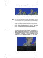
Clouds . . . . . . . . . . . . . . . . . . . . . . . . . . . . . . . . . . . . . . . 224
Sarah . . . . . . . . . . . . . . . . . . . . . . . . . . . . . . . . . . . . . . . 225
Bricks . . . . . . . . . . . . . . . . . . . . . . . . . . . . . . . . . . . . . . . 226
Furnace
The Foundry
Contents
Appendix A
xv
229
Release Notes . . . . . . . . . . . . . . . . . . . . . . . . . . . . . . . . . . . . . 229
Furnace 3.1v1 . . . . . . . . . . . . . . . . . . . . . . . . . . . . . . . . . . 229
Furnace 3.0v6 . . . . . . . . . . . . . . . . . . . . . . . . . . . . . . . . . . 230
Furnace 3.0v5 . . . . . . . . . . . . . . . . . . . . . . . . . . . . . . . . . . 230
Furnace 3.0v4 . . . . . . . . . . . . . . . . . . . . . . . . . . . . . . . . . . 231
Furnace 3.0v3 . . . . . . . . . . . . . . . . . . . . . . . . . . . . . . . . . . 232
Furnace 3.0v2 . . . . . . . . . . . . . . . . . . . . . . . . . . . . . . . . . . 233
Furnace 2.0v2 . . . . . . . . . . . . . . . . . . . . . . . . . . . . . . . . . . 235
Furnace 2.0v1 . . . . . . . . . . . . . . . . . . . . . . . . . . . . . . . . . . 236
Furnace 1.1v3 . . . . . . . . . . . . . . . . . . . . . . . . . . . . . . . . . . 237
Furnace 1.0v2 . . . . . . . . . . . . . . . . . . . . . . . . . . . . . . . . . . 238
Furnace 1.0v1 . . . . . . . . . . . . . . . . . . . . . . . . . . . . . . . . . . 239
Furnace 1.0b4 . . . . . . . . . . . . . . . . . . . . . . . . . . . . . . . . . . 240
Furnace 1.0b3 . . . . . . . . . . . . . . . . . . . . . . . . . . . . . . . . . . 240
Furnace 1.0b2 . . . . . . . . . . . . . . . . . . . . . . . . . . . . . . . . . . 241
Furnace 1.0b1 . . . . . . . . . . . . . . . . . . . . . . . . . . . . . . . . . . 243
Appendix B
244
End User License Agreement . . . . . . . . . . . . . . . . . . . . . . . . . . . . . 244
Appendix C
252
Kronos Algorithm . . . . . . . . . . . . . . . . . . . . . . . . . . . . . . . . . . . 252
Introduction . . . . . . . . . . . . . . . . . . . . . . . . . . . . . . . . . . . 252
Terminology . . . . . . . . . . . . . . . . . . . . . . . . . . . . . . . . . . . 252
Producing vectors . . . . . . . . . . . . . . . . . . . . . . . . . . . . . . . . 253
Index
The Foundry
254
Furnace
16
INTRODUCTION
Introduction
Welcome to this User Guide for Furnace on Discreet.
Furnace is a rich collection of image processing tools to help
compositors tackle common problems when working on lms.
We have spent several years working closely with universities
and post production houses in London developing tools that
will save you time.
About this User
Guide
This User Guide will tell you how to install and use the Furnace sparks. Licensing Furnace is covered in the separate
Foundry FLEX Tools User Guide.
Throughout this user guide we assume you are familiar with
Autodesk Media & Entertainment Solutions and the machine it
is running on.
Notation
All the directory and le names in this document are the 32 bit
versions. For the 64 bit equivalent, simply substitute 64 for
32 in any of the relevant names.
The phrase Discreet Flame is used to denote any of the
compatible Autodesk Media & Entertainment Solutions, Discreet® Flame®, Discreet® Flint®, Discreet® Fire®, Discreet® Inferno®, and Discreet® Smoke®.
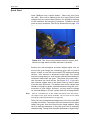
Example Images
Example images are provided for use with each of the sparks.
You can download these images from our web site.
Installing Furnace on
Discreet Irix
Downloads are available from www.thefoundry.co.uk.
1. Log in as root
2. Download the Furnace software. You should get a le
called
Furnace3.1v1_Spark4.0-irix-mipsrelease-32.tardist
Furnace
The Foundry
17
Installing Furnace on Discreet Linux
3. Install the default software using the inst command (or,
if you prefer, use the Software Manager)
inst -f Furnace3.1v1_Spark4.0-irixmips-release-32. tardist
Inst> list
Inst> install *
Inst> go
Inst> quit
4. The plug-ins are installed to /usr/discreet/sparks/Furnace3.1v1
5. Proceed to licensing Furnace.
Installing Furnace on
Discreet Linux
Downloads are available from www.thefoundry.co.uk.
1. Log in as root
2. Download the Furnace software. You should get a le
called
Furnace3.1v1_Spark4.0-linux-x86release-32.run
3. Install the software with the command
./Furnace3.1v1_Spark4.0-linux-x86release-32.run
4. The plug-ins are installed to /usr/discreet/sparks/Furnace3.1v1
5. Proceed to licensing Furnace.
Installing Furnace on
Burn
Downloads are available from www.thefoundry.co.uk. On each
linux machine running Burn:
1. Log in as root
2. Download the Furnace software. You should get a le
called
Furnace3.1v1_Spark4.0-linux-x86release-32-Burn.run
3. Install the software using the command
./Furnace3.1v1_Spark4.0-linux-x86release-32-Burn.run
The Foundry
Furnace
18
INTRODUCTION
4. The plug-ins are installed to /usr/discreet/sparks/Furnace3.1v1
5. Repeat this for each burn station.
6. No license is required for Furnace on Burn. All Burn
versions of the software are provided free of licensing
so you may install and use this software on as many Burn
nodes as you have available to you.
Note
The Furnace 3.1 sparks must have EXACTLY the same directory path as
the Furnace 3.1 on Flame. If they are different, remote rendering of these
sparks on Discreet will fail.
Licensing Furnace
Furnace uses FLEXlm encryption in the license keys. Node
locked and oating licenses are supported. You can get time
limited demo licenses from our web site or by contacting The
Foundry directly. You will need the lmhostid of your machine
to get a license. The lmhostid is a unique number for your
machine. To display this number, download the Foundry System
ID utility from our web-site www.thefoundry.co.uk/licensing.
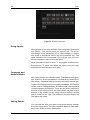
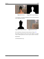
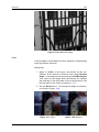
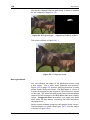
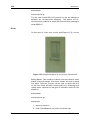
Without a valid software license key, Furnace plug-ins will
render diagnostic text to help you identify the problem with
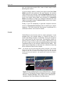
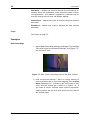
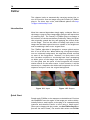
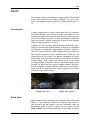
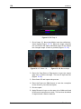
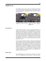
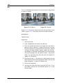
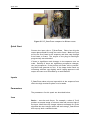
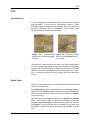
the license. (Figure 1.1).
Figure 1.1 Unlicensed spark.
For information on licensing Furnace, displaying the lmhostid,
setting up a oating license server, adding new license keys
and managing license usage across a network you should read
Furnace
The Foundry
19
Removing Furnace from Irix
the Foundry FLEXlm Tools (FFT) User Guide which can be downloaded from our web site.
Removing
Furnace from
Irix
If you wish to completely remove Furnace 32 bit sparks from
your system, use the following command as root.
versions remove Furnace3.1v1_Spark4.0irix-mips-release-32
or to remove the 64 bit sparks
versions remove Furnace3.1v1-Spark4.0irix-mips-release-64
Documentation
This User Guide is installed alongside the sparks in a directory
called docs.
Network Rendering
A number of plug-ins in Furnace require cached data from previous frames to generate a new frame. Batch scripts containing
these sparks will render correctly if executed locally on your
Discreet system, but will fail if rendered using Burn across multiple machines on a network, as these cached frames will not
be available to construct the new frame.
These network rendering restrictions apply to the following
sparks or parameter settings.
ˆ DeFlicker.
ˆ DeGrain with temporal switched on.
ˆ Steadiness with the reference set to Previous.
ˆ WireRemoval with tracking switched on or rendering with
RollingRepair.
ˆ BlockTexture with Temporal Consistency switched on.
ˆ Splicer with Temporal Consistency switched on.
ˆ Correlate.
The Foundry
Furnace
20
INTRODUCTION
About Furnace
Plug-ins
All Furnace plug-ins integrate seamlessly into Discreet. They
are applied to your clips as you would any other spark and they
can all be animated using the standard animation tools.
Other Foundry
Products
The Foundry is a leading developer of plug-in visual effects for
lm and video post production. Its products include Furnace,
Tinder, Tinderbox, Keylight and Anvil and run on a variety of
compositing platforms including Flame, Flint, Fire, Inferno and
Smoke from Discreet, Shake, Avid|DS and After Effects. For the
full list of products and supported platforms see our web site
www.thefoundry.co.uk
Tinder and Tinderbox are collections of image processing effects including blurs, distortion effects, background generators, colour tools, wipes, matte tools, paint effects, lens ares
and much more.
Anvil is a collection of colour correction and colour manipulation tools originally developed by First Art.
Keylight is an award winning blue/green screen keyer giving
results that look photographed not composited. The Keylight
algorithm was developed by the Computer Film Company who
were honoured with a technical achievement award for digital
compositing from the Academy of Motion Picture Arts and
Sciences.
Visit The Foundry's web site at www.thefoundry.co.uk for further details.
Furnace
The Foundry
21
Basics
This section will tell you some basic information about sparks.
Skip this if you are familiar with Discreet.
What is a Spark?
A spark is a small computer program that can be loaded onto
your Discreet system to do a speci c task. Other manufacturers call them plug-ins. Once loaded, a spark behaves as
an integral part of your Discreet system and appears in the
Effects menu just like the built-in effects.
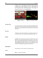
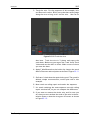
Where are the
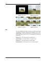
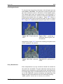
Sparks?
The sparks buttons are in the Effects menu on most Discreet
systems. You can have up to ve sparks loaded at any one time.
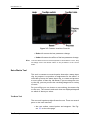
The name of the currently loaded spark is shown on the spark
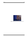
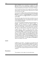
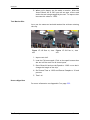
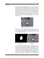
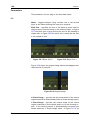
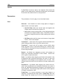
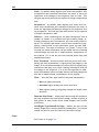
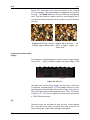
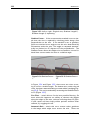
button. In the Figure 2.1 the Tinder sparks T_Distorto, T_Dilate,
T_LensFlare, T_BlurMasked, T_RomanMosaic have been loaded.
If a button does not have a spark loaded it will display the
word Spark on the button.
Figure 2.1 Flame user interface showing Sparks buttons.
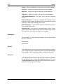
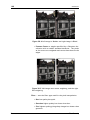
Loading Sparks
To load a spark either click on the button (if it says Spark)
or hold down the Alt key and click on any spark button (if
it already has a spark loaded). This will display the sparks
browser. Select the Furnace spark you want to load from the
directory /usr/discreet/sparks/.
The Foundry
Furnace
22
BASICS
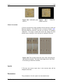
Figure 2.2 Sparks browser.
Using Sparks
Using a spark is not much different from using one of Discreet's
own effects. Click on the spark you want to use. The cursor
will change colour prompting you to select images or mattes
and nally a destination reel to put the processed clip. The
spark interface will be launched. This will give you access to
all the parameters that control the spark.
When you select a spark a letter "S" may appear on the button.
Pressing this "S" letter will launch the spark using the clips
selected last time the spark was used.
Command and
Module Modes
All Furnace sparks run in Module mode. The Module mode gives
you access to all the parameters and animation channels for
that effect. Command mode processes the clip(s) without giving the user the opportunity to change parameters. No Furnace
sparks work in Command mode. All sparks have some standard
controls supplied by Discreet. These are the three columns of
buttons on the lefthand side, the frame slider and play control
buttons in the middle and the image window display controls
(pan & zoom) on the right. The remaining controls depend on
that particular spark.
Saving Sparks
You can load and save your spark's current parameter settings
from the Setup menu. See your Autodesk Media & Entertainment User Guide for more information.
Furnace
The Foundry
23
Common
Controls
There are many controls that are common to the Furnace
sparks. These are all described in detail in this chapter.
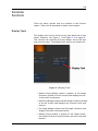
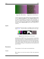
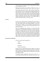
Display Tools
The display tools can be found on the right hand side of the
sparks interface. See Figure 3.1 and Figure 3.2 on page 25.
This controls the rendering of proxy images, shows tool tips
and onscreen tools. The display tools options are listed here.
Figure 3.1 Display Tools.
ˆ Quarter Proxy Widget renders a quarter of the image
resolution (scaled to t the screen) and displays the onscreen tools and buttons.
ˆ Half Proxy Widget renders half the image resolution (scaled
to t the screen) and displays the onscreen tools and
buttons.
ˆ Full Image Widget renders the full image resolution and
displays onscreen tools and buttons.
ˆ Quarter Proxy renders a quarter of the image resolution (scaled to t the screen) without onscreen tools and
buttons.
The Foundry
Furnace
24
COMMON CONTROLS
ˆ Half Proxy renders half the image resolution (scaled to
t the screen) without onscreen tools and buttons.
ˆ Full Image renders the full image resolution without onscreen tools and buttons.
Help
Press the Help button to display a brief overview of the currently loaded Furnace spark. The help page also shows the
version of the Furnace spark. To hide the help page press the
Help button again. See Figure 3.2 on the facing page.
Tooltips
Switch this on to display information about the currently selected parameter. See Figure 3.2 on the next page.
Process
Controls when to process the effect. The default setting is
Penup. See Figure 3.2 on the facing page. The options are:
ˆ Preview will only render the image if the Preview button is pressed. This enables you to tweak parameters
without waiting for the plug-in to process. If you hit the
Process button with Process set to Preview, the value
will be automatically changed to Pen Up, so that the clip
actually gets processed.
ˆ Penup will render the image when you release the mouse
button or pen.
ˆ Drag Small will continually render a proxy image as you
alter a parameter value.
ˆ Drag will continually render the whole image as you alter
a parameter value.
Reset
Enables the default spark values to be restored. Undo and
Redo functions are also included in this group. See Figure5 on
page23. The options are:
ˆ Reset All will restore default values to all parameters on
all pages.
ˆ Reset Page will restore default values just to the current
page.
Furnace
The Foundry
25
Roto/Matte Tool
Figure 3.2 Common Interface Controls.
ˆ Redo will restore the last parameter change.
ˆ Undo will remove the effect of the last parameter change.
Note
The reset buttons will not remove keyframes in the animation curves. They
will simply restore the default values to the parameters at the current
frame.
Roto/Matte Tool
This tool is common to several sparks that take a matte input
clip. Its purpose is to produce a rough matte for the effect. It
will either process the matte input clip, or create and process
a roto in place of that clip. No matter if you are using the roto
or the clip, you can process the resulting image with a variety
of tools.
For your effect you can choose to use nothing, the matte clip
or the roto. The controls and tools that are displayed depend
on which of these you select.
The Roto Tool
The roto tool is quite straight forward to use. There are several
parts to the tool interface:
ˆ the roto outline, control points and tangents. See Figure 3.3 on the next page.
The Foundry
Furnace
26
COMMON CONTROLS
ˆ the roto axis, controlling its translation (red cross hairs),
rotation (green arrow) and scale (blue box). See Figure
3.3.
Figure 3.3 Roto Shape.
ˆ the roto animation timeline, and keyframes. See Figure
3.4.
Figure 3.4 Roto Timeline.
ˆ the buttons on the Roto/Matte control page to manipulate the roto.
Creating a new roto
To create a new roto you simply draw the shape you want by
pressing down and dragging the pen. A green line will trace
your pen path. Once you release the pen, a roto will be created
that has the minimum number of control points that accurately
matches the shape you drew.
If you want a simple shape to start with, choose one from the
Shape popup. See Figures 3.5 and 3.6.
Furnace
The Foundry
27
Roto/Matte Tool
Figure 3.5 Square Roto.
Figure 3.6 Circular Roto.
Control Points
Control points are drawn as small circles around the roto shape
(or squares if the Bezier toggle is not turned on). If a control
point is currently selected it will be drawn with a red centre.
To move a control point simply click and drag it.
To select multiple control points, drag a selection box over
the points you want.
To move multiple control points, simply click on any one of
the selected points and move it.
To deselect control points, click on the screen away any selected points.
To delete control points, click on one of the selected points
and drop it in the rubbish bin at the bottom left of the screen.
The bin will only appear when the control point gets close. The
cursor turns into a red - shape and the bin's lid will raise
when you have reached the bin.
To add a new control point move your cursor over the edge of
the curve and it will turn into a green + shape and a ghostly
green key appear. Now simply click on the outline of the curve
and a new point will be created with automatic tangents.
Tangents
If your roto is a Bezier shape, then it will have a pair of tangents
displayed at each control point. These control how smooth the
curve is between control points. To move a tangent, simply
click and drag on it. You can only modify one tangent at a
time.
There are three types of tangents:
1. Split Tangents drawn with solid lines and triangular
ends; paired tangents are independent so that changThe Foundry
Furnace
28
COMMON CONTROLS
Figure 3.7 Bin/Trash to delete control points.
ing one will not change the other. Use these to get sharp
corners.
2. Linked Tangents drawn with solid lines and solid circular
ends; paired tangents point 180 degrees away from each
other; dragging one tangent will change the angle but not
the length of the other tangent so that is always 180
degrees away.
3. Automatic Tangents drawn with dashed lines and hollow
circular ends; paired tangents point 180 degrees away
from each other; there is no user control over these
tangents; the length and angle of the tangents are automatically calculated to make a smooth curve by looking
at the position of nearby control points. Moving any of
these control points will change the tangent.
To change the tangent type you quickly click on the tangent
end without moving it. The tangent will then cycle between the
various types.
If you have an automatic tangent and you drag it, it will always
turn into a linked tangent (otherwise you couldn't move it).
Rotation, Animation and Timeline
The roto shape can animate, saving the whole shape at each
key, points, tangents and tangent types. For frames where
there are no keys, a shape will be interpolated using the surrounding two keyframes.
Furnace
The Foundry
29
Roto/Matte Tool
If the roto has any animation, the outline will be drawn solid if
there is a key at the current frame, otherwise it will be drawn
dashed.
If the AutoKey button is on, every time you manipulate the
roto, a keyframe will be added. You can also add a key at the
current frame by clicking the Add Roto Key button.
If there is a key at the current frame you can delete it by
clicking on the Delete Roto Key. The button, Delete Animation,
will remove all roto keys.
Just above the Spark timeline we display the roto timeline. We
do this to show the location of the keyframes. Each keyframe
is drawn as a small triangle, with the current frame being drawn
as a yellow bar.
Figure 3.8 Roto Timeline.
You can change the frame a key is on simply by clicking and
dragging it in the timeline, its frame number will be displayed
next to it.
The range of frames being displayed in the timeline can be
changed using the tools inside it (Figure 3.9 on the following
page), they are...
ˆ a lock icon, which indicates that the displayed timeline
is locked to the Discreet timeline.
ˆ a frame all icon, which will break the lock to the Discreet
timeline, and set the range so that all keys are visible.
ˆ a pan icon, which will break the lock to the Discreet
timeline, and slide the range of visible frames up and
down.
ˆ two zoom icons, which will zoom into and out of the
timeline.
ˆ two arrow icons at the very end of the timeline, which
indicate that more keys are off the end of the timeline
The Foundry
Furnace
30
COMMON CONTROLS
and not visible. Click on these and the timeline will rearrange itself so that all keys off that side are now visible.
Figure 3.9 Roto Tools.
Roto Axis
The axis allows you to move, rotate and scale the roto. It is
drawn in the image overlay as a red cross hair with a blue box
and green anchorlike handle. The red cross hair allows you to
move the roto by clicking and dragging it. If you select just
one of the arms, you will move the roto only in that direction.
This is linked to the Translate X and Translate Y parameters
on the Roto/Matte control page.
Figure 3.10 Roto Axis Controls.
The blue rectangular box allows you to scale the roto about
the centre of the axis. If you select a corner you will scale
in x and y, if you choose a single side, you will scale only in
that direction. This is linked to the Scale, Scale X and Scale Y
parameters on the Roto/Matte control page.
Furnace
The Foundry
31
Roto/Matte Tool
The green anchor allows you to rotate the roto about the
centre of the axis. This is linked to the Rotate parameter on
the Roto/Matte control page.
Roto Data Storage
Rotos are saved by encoding them into a Discreet animation
curve. If you look in the animation sheet you will see a folder
called PrivateData, this is where they are stored. Do not open
this folder and do not attempt to modify the keys inside, it can
and will cause problems with the roto.
Roto Parameters
The parameters for the roto group are described here. and
shown in Figure 3.11.
Figure 3.11 Roto Parameters.
Mode - this usually speci es whether the effect will use a roto
shape, external matte, or something else. In F_BlockTexture
this parameter is called Fill because it is used to control where
to ll the image with texture.
ˆ Roto - the spark uses the roto shape.
ˆ Matte - the spark uses the matte input.
ˆ None - the spark ignores any matte or roto shape.
Invert - switch this on to invert the Roto or Matte.
Softness - sets the amount of blurring applied to the Roto/Matte.
Aspect - controls the horizontal and vertical weighting of the
blur. 100% blurs only in X, 100% blurs only in Y whilst 0%
blurs equally in X and Y.
Edges - this controls edge treatment of the matte.
ˆ Don't Process - no edge treatment,
ˆ Shrink/Grow - erodes or enlarges the Roto/Matte by the
Edge Push parameter. Negative values shrink it, positive
values grow it.
The Foundry
Furnace
32
COMMON CONTROLS
ˆ Halo In/Out - extracts only the edges of the Roto/Matte,
if Edge Push is negative, only the inside edge is extracted,
if Edge Push is positive, outside edges are extracted.
ˆ Halo - extracts the edges of the matte that is Edge Push
pixels wide.
Edge Push - how far to push the edges of the processed Roto/Matte.
Exactly what is done with the edges is controlled by the Edges
parameter.
Blur Inside Haloes - if Edges is set to Halo In/Out , any softness applied works on the side being grown.
Show Roto/Matte - this toggles the rendered output to be
either the processed roto/matte or the result of the effect.
Use this to display the Roto/Matte whilst you are tweaking it
for your effect.
Colour - sets the colour of the roto overlay, in case the default
black colour is dif cult to see against your image.
MatteOnly Controls
Clip Min - if processing the matte input clip, this sets the black
level of the matte.
Clip Max - if processing the matte input clip, this sets the
white level of the matte.
RotoOnly Controls
Shape - sets the initial shape of the roto. When you select
this, the current roto will be destroyed.
ˆ Circle - creates a circular roto shape. See Figure 3.6 on
page 27.
ˆ Square - creates a square roto shape. See Figure 3.5 on
page 27.
ˆ Freehand - select this to draw an irregular shape. You
should click and drag onscreen to draw out the shape
rather than click repeatedly to de ne control points for
the spline. See 3.3 on page 26.
Bezier Roto - switch this on for a smooth Bezier curve between the control points Figure 3.12 on the facing page, or
switch it off for a polygon Figure 3.13 on the next page.
Tran X - sets the horizontal position of the roto shape. Change
this to move the shape right and left. This is linked to the onscreen red cross hair.
Furnace
The Foundry
33
Crops
Figure 3.12 Bezier.
Figure 3.13 Polygon.
Tran Y - sets the vertical position of the roto shape. Change
this to move the shape up and down. This is linked to the
onscreen red cross hair.
Rotation - this controls the rotation of the roto and is linked
to the onscreen green anchor in the roto axis.
Scale - sets the size of the roto shape. Change this to make
the shape bigger and smaller. This is linked to the onscreen
blue rectangle.
Scale X - sets the horizontal size of the roto shape. Increase
this to stretch the shape width. This is linked to the vertical
edges of the onscreen blue rectangle.
Scale Y - sets the vertical size of the roto shape. Increase this
to stretch the shape height. This is linked to the horizontal
edges of the onscreen blue rectangle.
Add Roto Key - this will add a keyframe to the roto animation
at the current frame.
Delete Roto Key - this will delete a keyframe from the roto
animation if one exists at the current frame.
Delete Animation - this will delete all keyframes from the roto
animation, but it will keep the current roto.
Delete Roto - this will delete all keyframes from the roto animation and delete the current roto as well.
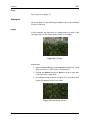
Crops
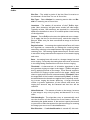
This group of seven controls (Figure 3.14) enables the image
to be cropped and de nes the value of pixels outside the rectangular cropping area.
X Crop - sets the behaviour of the image at its left and right
boundaries.
ˆ Wrap - uses the pixels from the opposite edge.
The Foundry
Furnace
34
COMMON CONTROLS
Figure 3.14 Crop Controls.
ˆ Re ect - mirrors the image at the boundary.
ˆ Repeat - repeats the last line of pixels at the boundary.
ˆ Colour - uses a solid colour. This colour is set by the
colour pot at the bottom of this group of controls.
Y Crop - sets the behaviour of the image at its top and bottom
boundaries.
ˆ Wrap - uses the pixels from the opposite edge. Figure 3.18 on the facing page.
ˆ Re ect - mirrors the image at the boundary. Figure 3.17
on the next page.
ˆ Repeat - repeats the last line of pixels at the boundary.
Figure 3.16 on the facing page.
ˆ Colour - uses a solid colour. Figure 3.15 on the next
page. This colour is set by the colour pot at the bottom
of this group of controls.
Left - sets the position of the left crop.
Right - sets the position of the right crop.
Bottom - sets the position of the bottom crop.
Top - sets the position of the top crop.
Colour - sets the colour that will ll the image outside the
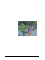
crop boundaries, if the cropping method is set to Colour.
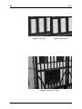
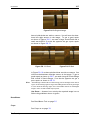
In the this example, the image of the elephant has been cropped
on all sides. The behaviour of the pixels is shown for all four
cropping methods.
Furnace
The Foundry
35
Box
Figure 3.15 Colour.
Figure 3.16 Repeat.
Figure 3.17 Re ect.
Figure 3.18 Wrap.
Box
The area sampled for motion or texture is de ned by the red
rectangular box shown onscreen when Display is set to Full
Image Widget. The size and position of this box can be altered using the onscreen tools, or by changing the following
parameters:
Sample Left - the left position of sample region.
Sample Right - the right position of sample region.
Sample Top - the top position of sample region.
Sample Bottom - the bottom position of sample region.
The Foundry
Furnace
36
ALIGN
Align
This chapter looks into using F_Align for matchmoving, stabilisation, and alignment. For hints, tips, tricks, and feedback
please visit http://support.thefoundry.co.uk.
Introduction
F_Align is arguably one of the most powerful sparks within
Furnace as it has so many possible applications. In its most
basic form the spark aligns a source image with a reference
image by applying a global transformation to the source image. This transformation is able to take account of changes in
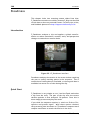
translation, rotation, scale, and perspective between the images. This is achieved without the artist needing to manually
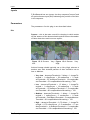
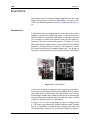
Figure 4.1 F_Align used to matchmove two clips into one.
select tracking points. Some of the applications for this motion
analysis are:
ˆ Stabilisation - each frame in a sequence can be aligned
with a single reference frame. For a stabilisation technique that preserves the original camera pan, see both
F_Steadiness on page 208 and Stabilisation on page 44.
ˆ MatchMoving - the data calculated to do the stabilisation can be inverted and applied to another clip to do a
match move. See MatchMoving on page 43.
ˆ Multiple Pass Alignment - two camera passes (across
the same scene) can be locked together by aligning each
frame in one clip with its corresponding frame in the second clip. This is very useful for locking the clips together
Furnace
The Foundry
37
Quick Start
where a motion control shot has proved defective, or
where the original passes were not motioncontrolled at
all. See Multiple Pass Alignment on page 72.
ˆ Clean Area Alignment - on a long pan following a foreground object, we can align an image a few frames before
the current one into position on the current frame, to
provide a quick clean area for replacing the foreground
object. See Clean Area Alignment on page 40.
Quick Start
To align one clip with a static frame from the same clip, load
the Spark using the clip as all three inputs, and hit process.
If the motion in the clip eventually deviates too far from the
initial frame we are using as a reference, the match will start
to fail. See the description of the Incremental button below
for a solution.
Inputs
F_Align has three inputs. The rst input (Source) will be the
sequence which is transformed and output during processing.
The second input (Reference) is the clip we derive motion from,
either by matching frames from the Source against the reference, or by matching frames in the Reference clip alone. The
third input (Reference Mask) can be used to specify the region
of the frame to be stabilised as an alternative to the onscreen
rectangular box or roto shape.
Parameters
The parameters for this spark are described below.
Align
Analyse - turns on and off analysis mode. Analysis mode
should normally be turned on the spark then does full motion
analysis and stores the results. It should subsequently be
turned off if you want to reprocess the spark with the same
setup but different input clips.
Frame - selects the reference method used. You are either
trying to lock a clip down to one particular frame (static) or
you are trying to line up each frame of one clip with each
corresponding frame of the other clip (relative).
ˆ Relative - select this to align a frame in the Source or
Reference clip with a slipped frame from the Reference
clip.
The Foundry
Furnace
38
ALIGN
ˆ Static - select this to align a frame in the Source or
Reference clip with a single frame somewhere in the Reference clip.
Match - selects the match method used.
ˆ Source to Ref - when aligning frames, align frames from
the Source clip so that they match frames from the Reference clip.
ˆ Ref to Ref - when aligning frames, align frames from
the Reference clip with another frame from the same
Reference clip.
Relative/Static Frame - when the reference method is set to
Frame: Static, this control stores the frame number of the
single static frame in the Reference clip we want to match
to. When the reference method is set to Frame:Relative, this
control stores the offset from the current frame number where
we index into the Reference clip. In this last case, for example,
if we are currently on frame 20, and the Relative Frame is 5,
then we will be matching frame 20 to frame 15.
Incremental - this button only appears when Match is set to
Ref To Ref (i.e. we are calculating all motion from one clip).
For example, if we try to match frame 20 to frame 1 of the
same clip, we have a choice of calculating the motion in one hit
(Incremental off), or by calculating the motion as the sum of all
of the individual motion transforms from frame 20 all the way
back to frame 1 (Incremental switched on).
The latter (Incremental on) is more likely to lockon even for
extreme motions over long frame ranges. The former (Incremental switched off) is more likely to give a pixelperfect match
between the frames, if one exists.
Clear Motion Cache - when using this Spark on the Discreet
Desktop, you may choose to run the Spark again with a different clip, without unloading the Spark. In this case, the Spark
is unaware that the clip has changed. Clicking on this button forces the Spark to dispose of its internal data tables and
recalculate the motion.
Scale - switch this on to correct for scale changes in the transformation.
Rotate - switch this on to correct for rotational changes in
the transformation.
Translate - switch this on to correct for translational changes
in the transformation.
Perspective - switch this on to correct for perspective changes
in the transformation.
Furnace
The Foundry
39
Parameters
Region - a mask can be used to indicate the area of the image
to use during matching. For example, you may wish to concentrate only on a moving foreground object and ignore the
background. The area ignored is where the mask is black.
ˆ Mask - use the Ref Mask input clip.
ˆ Roto - use the embedded Roto tool to produce a mask.
ˆ All - use the all of the frame.
Filter - is used to control the quality of your processed images
by reducing the jagged lines characteristic of pixel devices. To
render high quality images you should switch ltering on. With
all image processing you have a trade off between quality and
time. Filtering will increase the quality of your image but will
also increase the time it takes to process the image.
ˆ High - sinc ltering gives excellent results but is slower
to render than the others.
ˆ Medium - bilinear ltering.
ˆ Low - point sampling can give poor results but is faster
to process.
Show Reference - it can be useful to quickly view the actual
image that is being used as the reference to match to on the
current frame. Switching this on will show the reference image
blended with the current output.
Reference Blend - when Show Reference is switched on, this
controls the amount of the blend between the current reference
image and the output.
Slip Source - allows you to offset the Source clip when doing
Relative matches.
Slip Reference - allows you to offset the Reference clip when
doing Relative matches.
Step Size - it is rarely necessary to nd the optimum transformation for all pixels and so, to speed up the process, the
image is sampled with a frequency of Step Size, and only these
pixels are used to nd the transformation. Decreasing step
size will increase both the processing time and the quality of
result.
Scale Transform - when the Source is transformed to produce
the output, you can modify the amount of the transform applied
by using this control. A value of 0% will not transform the
Source at all. This control can be useful if you wish to match
the motion of a foreground object so that it only partially reacts
to the background.
The Foundry
Furnace
40
ALIGN
Invert Transform - if you wish to match move a Source clip
with no camera move to match the motion in the Reference
clip, then you will need to invert the transform applied to the
Source so that it shows the motion required to destablise the
Reference rather than the motion used to stabilise it. See the
example on page 43.
Roto/Mask
See Roto/Matte Tool on page on page 25.
DataOut
These parameters store the motionderived transform for the
image sequence. With Analyse checked off, only this data
will be used. It will almost never be useful to edit this data,
but it may be worth understanding what it represents. The
parameters are pixel offsets for each of the four corners of
the image. BL, BR, TL, TR denote bottom left, bottom right, rop
left, and top right corners of the image respectively. Together,
these show a four corner warp which represents the transform
at the current frame.
Crops
See Crops on page 33.
Examples
All the images for the following examples can be downloaded
from our web site.
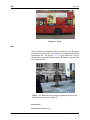
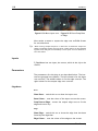
Clean Area Alignment
In this example, we will use the footage of a bike travelling
from left to right across the screen. Let's assume we want to
remove this motorbike by compositing pixels from a clean plate
over the bike. F_Align can help us create a clean plate, or more
accurately a clean area, by offsetting the clip and lining it up
with the reference frame. If we have a rough matte of the bike
we wish to remove we can use Effects Composite to pull pixels
from the aligned clip through the matte and over the reference
clip.
Download File
rigsbike.tar.gz
Furnace
The Foundry
41
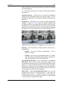
Examples
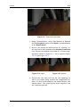
Step by Step
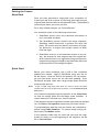
1. Import bike.#.tif.
2. Load F_Align into a Sparks button and click on the bike
for all the inputs. Set the parameters to their defaults
with Reset All.
3. Switch Frame to Relative.
4. Got to frame 15 on the timeline.
5. Change Slip Source to 5 to offset the Source clip by ve
frames as shown in Figure 4.2.
Figure 4.2 Screenshot.
6. Flip the display between the Reference (F2) and the Result (F4), and note that we now aligned a frame ve
frames ago with the current frame. This provides a rapid
mechanism for aligning a cleaner frame elsewhere in the
sequence over the foreground bike object in the current
frame.
7. Switch Perspective on to adjust for the slight perspective
shift between the frames. Perspective is a very processor
intensive option, but the match between the two frames
around the windows on the top right should be slightly
better.
8. Process and Exit to the reels.The output clip can now be
used as a source of pixels to remove the motorbike. To
do this we need a matte of the bike that will de ne the
region to paint through. We can use the roto tools in
F_Align.
9. From the reels, select F_Align and load the bike.
The Foundry
Furnace
42
ALIGN
10. Reset All, View the Source (F1) and select the Roto/Mask
edit group. Move to frame 1.
11. Toggle Masking:Box to Masking:Roto and click and drag
over the image to draw a rotospline around the bike. It
does not have to be accurate, we just need a rough shape.
Note that clicking control points to de ne the spline will
not create a roto. You have to click and drag to draw a
line. Release the mouse/pen when you're near the start
to complete the closed shape.
Figure 4.3 Roto screenshot.
Figure 4.4 Close-up of roto.
12. You need to keyframe the roto shape to cover the bike as
it moves off screen. Move to frame 10 and move the roto
using the red crosshairs. Move to frame 20 and repeat.
You may need to scale the shape as the bike moves into
the distance.
13. View the result (F4) and switch on Show Roto/Matte to
render the matte. Process and Exit. We now need to
paint through from the aligned sequence over the original bike clip. To do this we can use Flame's builtin
compositing tools.
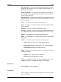
14. Select Effects -> Compositor and select F_Align, then the
bike then the roto matte. This composites the clean area
over the bike using the matte.
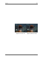
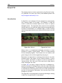
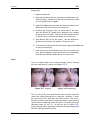
Figure 4.5 Before.
Furnace
Figure 4.6 After.
The Foundry
43
Examples
15. Process.
16. That's it.
Note
This example could also be solved using F_RigRemoval on page 173.
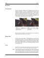
MatchMoving
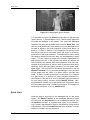
In this example, we re going to use F_Align to stick a new poster
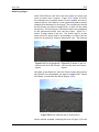
(Figure 4.7) on the side of a moving bus (Figure 4.8).
Figure 4.7 Poster.
Figure 4.8 Bus.
Download File
alignbus.tar.gz
Step by Step
1. Import bus.#.tif, busMatte.tif and busLogo.tif
2. Load F_Align into a Sparks button and click on the busLogo then the bus, then the bus again for the three inputs.
Reset the spark.
3. Switch the Match popup to Ref To Ref, to show we are
only interested in motion on the Reference clip (the bus).
4. Set Static Frame to 25. This frame corresponds to the
position of the poster. In other words, if you composite
the static poster image over the bus without moving the
poster it will line up on frame 25.
5. On the Crops/Box control page, set the X Crop and the
Y Crop popups to Colour.
6. Back on the Main control page, click Incremental on. The
Spark will now pause while it analyses interframe motion
from the current frame (frame 1) up to frame 25.
7. Click on Invert Transform, to apply the move to the
Source clip (otherwise by default we are applying the
stablisation transform to the Source).
The Foundry
Furnace
44
ALIGN
8. Process the sequence to generate the moving poster that
we can composite over the bus.
9. Exit the spark. Now we must repeat this move on the bus
matte, since we ll need a matte to composite the poster
over the bus. Select F_Align again and click on the bus
matte then the bus and the bus again and process.
10. Exit the spark and using Quick Composite, layer the
aligned poster over the bus using the aligned matte, as
shown in Figure 4.9.
Figure 4.9 Poster on bus.
11. You can get a closer match by reprocessing with the
onscreen selection box positioned over the bus on the
left part of the frame only.
12. If you want to apply the same move to subsequent elements, like the matte, you may nd it quicker to rst
reload the Spark with the original clips and original settings, click Analyse off, and then save the setup. If you
then use this setup for subsequence clips the same move
will be applied without the cost of reanalyzing the motion.
Stabilisation
In this example, we will use F_Align to stabilise a left to right
pan as shown in Figure 4.10 and Figure 4.11.
Download Files
alignjb1.tar.gz, alignjb2.tar.gz
1. Import JB1.#.tif. Play the clip.
Furnace
The Foundry
45
Examples
Figure 4.10 Poster.
Figure 4.11 Bus.
2. Load F_Align into a Sparks button and click on just JB1
for the three input clips. Reset the plug-in using Reset
All and Clear Motion Cache on the Main control page.
3. Set Frame to Static to show that we are stabilising to a
single frame.
4. Set Match to Ref To Ref to show that we are only interested in the relationship between frames on the Reference clip, and not interested in the relationship between
the Source and the Reference.
5. On the Crops/Box control page, set the X Crop and Y
Crop popups to Colour, so that we can see the outline of
the transformed image.
6. Back on the Main control page, set the Static Frame to
20 this is the reference frame we want to stabilise to.
7. Click Incremental on (note that this control is only visible
if Match is set to Ref To Ref). This means that rather than
calculating the transformation from the current frame to
frame 20 in one go, the plug-in calculates the sum of all
the incremental differences between the current frame
and frame 20 one frame at a time. You will need to wait
for this initial processing to nish.
8. Process the clip to produce the stabilised output. Figure
4.12 shows the translated and rotated frame 1 stabilised
around the fence post.
The Foundry
Furnace
46
ALIGN
Figure 4.12 Frame 1 sta- Figure 4.13 Frame 25 stabilised.
bilised.
Furnace
The Foundry
47
BlockTexture
Introduction
Furnace includes a number of texture generation sparks. These
are used to create resolution independent images that have
the same look and feel as a small sample region from a source
image. F_BlockTexture is one such spark and should be used for
replicating fairly large scale textures. By that we mean textures
that contain shapes rather than more uniform textures that
would be suited to F_PixelTexture. It works by taking blocks of
data from the original image and rearranging them in a random
fashion but in such a way that the joins between the blocks
are invisible and look plausible. The size of the blocks depends
on the scale of the texture being replicated and the overlap
of the blocks controls how well the joins between blocks are
hidden. This spark tends to generate the best results on more
natural looking textures, for example, leaves blowing in the
wind or even crowds of people. F_BlockTexture also has the
ability to generate temporally consistent frames of textures
but only over small motion ranges. For hints, tips, tricks, and
feedback please visit http://support.thefoundry.co.uk
Figure 5.1 Original image Figure 5.2 BlockTexture used
showing the river Thames in to generate moving water
London.
texture.
Quick Start
The spark takes a background image, two texture inputs, and
a matte input. The texture inputs will be sampled and used to
generate a new texture. The background input will have the
generated texture applied to it. The matte is an optional input
that allows you to specify a region in the background image
that you wish to ll with the new texture. This region can be
blended with the original image to produce a seamless ll. A
roto shape can be used instead of an external matte.
The Foundry
Furnace
48
BLOCKTEXTURE
Figure 5.3 The original image is shown on the left. This
image has recognisable shapes and is more suited to
F_Blocktexture. F_BlockTexture has been used to generate
the image in the middle which shows good shape retention.
For comparison, F_PixelTexture has been used on the right.
If you have more than one region in the matte, only one region will be lled with texture. Figure 5.4 shows two unconnected regions in the matte. Figure 5.5 shows the output of
F_BlockTexture. Note that only one region has been lled with
the brick texture. To get round this you would have to split
the matte up and apply Blocktexture separately to both mattes
then recombine the results.
Figure 5.4
mattes.
Unconnected
Figure 5.5 Result.
After connecting the texture inputs use the red rectangular
onscreen selection box to de ne the area that will be sampled
for texture. A larger source region will mean less noticeable
repetitiveness in the new texture.
Adjust Block Size to nd a suitable sized building block to
generate the new texture. Overlap determines the amount
adjacent blocks are overlap. A greater overlap gives a better
chance of hiding the edge join. If the edges are still visible
increasing Blend Size will blur the join but too much blurring
will result in a noticeable soft edge to the blocks. Increasing
Number of Samples will increase the quality of the t between
blocks but at the expense of processing time. The whole process is seeded by a random number so changing the Seed will
Furnace
The Foundry
49
Quick Start
give you alternative texture lls, some of which may be more
pleasing than others.
If you are using a matte to specify the region to be lled, Path
Width speci es the quality of the join between the texture
region and the source image. Similarly Edge Blend speci es the
extent to which this join is blurred. If there is luminance change
across the region being lled and switching on Luminance
Match will attempt to align the luminance between the new
region and original image. Luminance Blur controls the extent
of this matching process.
Finally, if you are attempting to generate temporal textures
switch on Temporal Consistency before rendering an output
sequence. This will ensure the new texture is generated in a
consistent manner on successive frames.
Crowds
F_BlockTexture can also be used for crowd replication. In the
example here, the original image is a locked off shot of a
small crowd lling only part of a stadium. During the sequence
the crowd stand up and wave ags. By drawing a matte to
specify where we want to put new crowd, F_BlockTexture can
be used to split up the crowd into plausible jigsaw pieces and
reassemble them in the locations de ned by the matte. This
spark works temporally, so that the new crowd also stand up
but at different times to the original.
Note
You should note that with temporalConsistency switched on the sample
texture will be taken from the sample region on the start frame only. Any
changes to the size or position of the sample region over the sequence
will be ignored by the algorithm. The algorithm also assumes the matte is
unchanging.
Figure 5.6 Crowd Replication using F_BlockTexture. Images
courtesy of The Moving Picture Company from the lm Mike
Bassett: England Manager 2001 Film Council, Hallmark Entertainment and Entertainment Film Distributors
The Foundry
Furnace
50
BLOCKTEXTURE
Inputs
F_BlockTexture has ve inputs. The rst input is the background over which the texture will be composited. The second
and third inputs are textures. The fourth input is an optional
matte to de ne the region that will be lled with generated
texture.
Tip
If you have just one image from which to sample texture you could rotate
and scale this to produce another texture image. Use the original texture
in the second input and the rotated/scaled texture for the third input.
By providing additional texture inputs you will reduce repetition in the
generated texture.
Parameters
The parameters for this spark are described below.
Texture
Fill - switch this on to ll the whole of the area de ned by the
source image with new texture as opposed to just the region
selected by the matte.
ˆ Roto lls the roto shape with texture.
ˆ Matte lls the external matte with texture.
ˆ Screen lls the whole screen with texture.
Avoid Fill Region - switch this on to sample texture from the
region that is not speci ed by the matte.
Sample Texture 1 - switch this on to use the Texture 1 input
as a source of the generated texture.
Sample Texture 2 - switch this on to use the Texture 2 input
as a source of the generated texture.
Sample Source - switch this on to use the Background input
as a source of the generated texture.
Sample Left - the left position of sample region. The sample
region is shown as a red rectangular box over the image.
Sample Right - the right position of sample region. The sample region is shown as a red rectangular box over the image.
Sample Top - the top position of sample region. The sample
region is shown as a red rectangular box over the image.
Sample Bottom - the bottom position of sample region. The
sample region is shown as a red rectangular box over the image.
Block Size - the size of the building blocks used to make the
new texture.
Furnace
The Foundry
51
Examples
Overlap - the amount the building blocks are overlap. A larger
overlap is more likely to generate a better edge join.
Blend Size - the amount of blur at the edges between building
blocks. A small amount is good to help hide the edges on some
images but too much will result in an obvious softness.
Number of Samples - the number of different blocks that are
tried before choosing the best match. The higher the number
the better the match but the longer the render time.
Seed - the random number used to start the texture generation process. Select another seed to see a different texture
pattern.
Temporal Consistency - switch this on to force temporal consistency in the new texture between successive frames. Note
that the sample region and the matte that the texture will
be pasted into, will be taken from the rst frame only. Any
changes to the sample region or matte on subsequent frames
will be ignored by the algorithm if Temporal Consistency is
switched on.
Warning
F_BlockTexture with Temporal Consistency switched on cannot be distributed across multiple machines on a network render farm. See Network
Rendering on page 19.
Path Width - sets the width of the join between the source
image and the new texture. The larger the path the better the
quality of join.
Edge Blend - the amount of blur between the source image
and the new texture. A small amount is good to help hide the
edges but too much will result in an obvious softness.
Luminance Match - switch this on to match the luminance of
the new texture with the luminance of the source region in
order to help hide the join.
Luminance Blur - controls how much effect Luminance Match
has on the new texture.
Roto/Matte
See Roto/Matte Tool on page 25.
Examples
A variety of textures can be downloaded from our web site.
The Foundry
Furnace
52
CHANNELREPAIR
ChannelRepair
This chapter looks at the repair of damage that occurs only in
one colour channel. For hints, tips, tricks, and feedback please
visit http://support.thefoundry.co.uk.
Introduction
Occasionally damage can occur in only one or two colour channels in an image, for example, a scratch may be only two channels deep or chemical damage may only affect the top layer of
the lm. In these cases F_ChannelRepair can be used to repair
the damaged channel(s) by using information from the other,
undamaged, colour channels.
Figure 6.1 Blue channel damage.
As with many of the other Furnace plug-ins this can also be
improved by using the Foundry's advanced motion estimation
technology to propagate clean pixels through the sequence.
With the default settings F_ChannelRepair will only use information from the current frame to make the repair. Turning on
Use Reference allows information from earlier in the sequence
or from an optionally supplied clean plate, to be motion interpolated to repair the damaged region. Where this not available
the algorithm automatically switches back to the spatial only
algorithm, Blend.
The rst spatial repair algorithm, Blend, tries to match the
statistics of the reference channel to the undamaged area of
the damaged channel. It then simply blends the matched pixels
of the reference channel to x the damage. The second algorithm, Rematch, is more complex and attempts to adjust the
local statistics of the proposed Blend repair to those in the
undamaged area. It is entirely dependent on the footage as to
which algorithm gives the best result.
Furnace
The Foundry
53
Quick Start
Figure 6.2 Undamaged green channel.
It is possible to tune the Rematch algorithm to improve the
repair quality. F_ChannelRepair uses a block based approach
to model the damage in the image. The clean and damaged
channels are split into multiple blocks of size Block Size. We
then try and modify the local statistics of the damaged block
to make it equal to the local statistics of the clean block. In
practice, if there is motion in the sequence the pixels in the
two blocks will not be the same which will result in incorrect
estimation of the local statistics. To minimise this effect, when
the image is divided into blocks they are overlapped by a small
region. To this region we apply the statistics calculated for
both adjacent blocks. If the results from these two blocks are
not consistent we assume that the parameters have been calculated incorrectly due to motion and we discard them both,
replacing them with the global statistics for the whole damaged region. The criterion for discarding parameters is set by
Motion Threshold. So, if you think the damage is only in parts
of the image that are static, it is quite safe to increase this
value. If there is little information in the block, for example
in a plain area, it is dif cult to obtain reliable estimates for
the statistics. We check for this by discarding the parameters
for any blocks with a variance below Weight Thresh. Having obtained a reliable set of parameters for each block these
are then smoothed using a combing technique. The number of
smoothing iterations is set by Smoothness.
Quick Start
Load the plug-in and click on the damaged clip for the three
inputs. Set Repair Channel to the damaged channel in need
of xing and set Use Channel to an undamaged channel. Set
the Method to blend. If a spatial only repair is not satisfactory, further improvements may be obtained by using motion
interpolation. Turn on Use Motion and move to frame 1 of the
sequence. Render out the sequence.
The Foundry
Furnace
54
CHANNELREPAIR
See also Kronos on page 122 for a more detailed description
of these parameters.
Figure 6.3 Repaired image.
Inputs
F_ChannelRepair has three inputs. The rst input (source)
contains the damaged frame or sequence. The second input (matte) should contain a frame or sequence that speci es
where the damage occurs. White areas are repaired. The third
input (reference) is an optionally supplied clean plate.
Parameters
The parameters for this plug-in are described below.
Repair
Method - there are two possible techniques to take information from one channel to repair another.
ˆ Rematch - attempts to make the local statistics between
Use Channel and Repair Channel identical.
ˆ Blend - feathers the duplicated pixels from Use Channel
into Repair Channel.
Repair Channel - selects the damaged channel of the image
to be repaired.
Use Channel - selects the undamaged channel of the image
from which to take information to make the repair.
Smoothness - sets the number of times the damage parameters are smoothed between blocks.
Use Reference - by default F_ChannelRepair uses only spatial
information from the current frame. Switch this on to allow
pixels from the a clean plate (second input) to be matchmoved
Furnace
The Foundry
55
Parameters
into the damaged region. Where pixels from other frames are
not available, the standard spatial repair is used.
Matte - sets the matte used to de ne the area of repair. This
can be set to the second input, or a rotomatte.
The following four parameters apply only to the rematch method.
Weight Thresh - sets the threshold value for plain areas above
which blocks are discarded due to the lack of reliable data. If
your results are poor, it's worth decreasing this value.
Motion Threshold - sets the threshold value above which localised damage is abandoned because of motion in the frame.
If your results are poor and you can see that there is little motion in the sequence, you should increase this value. Setting
the Motion Threshold to 1 will turn off localized damage repair
for all moving objects and apply a global algorithm to reduce
the damage.
Block Size - sets the size of the blocks that are analysed.
Smaller blocks will allow more complex damage to be modeled
but will produce less accurate and robust results, and will take
longer to render.
Roto/Matte
See Roto/Matte Tool on page 25.
Crops
See Crops on on page 33.
The Foundry
Furnace
56
COLOURALIGN
ColourAlign
This chapter looks at colour channel registration using Furnace's plug-in F_ColourAlign. For hints, tips, tricks, and feedback please visit http://support.thefoundry.co.uk.
Introduction
Occasionally due to damage to the lm or errors in the scanning
process the red, green and blue channels can become misaligned. F_ColourAlign will automatically repair this damage by
aligning the channels with a reference channel of your choice.
Figure 7.1 Mis-aligned.
Figure 7.2 Aligned.
Quick Start
Simply apply F_ColourAlign to the image to be aligned. Select
the reference channel that you wish the other channels to be
aligned to and view the result.
Normally the transformation causing the misalignment can be
modelled by a simple translation. In more complex situations it
may be necessary to calculate rotation, scale and perspective
changes by activating the relevant controls.
The quality of the interpolation of the misaligned channels can
be modi ed by adjusting the ltering parameter. Low is the
quickest but the image may look soft, medium uses a bilinear
lter and high uses a sinc lter for the best results but at the
expense of speed.
If, for some reason, the misalignment is only visible in part of
the image, switching on Use Region and setting the analysis
region to that part of the image will force the algorithm to
analyse only that part of the image. This may give better
results.
Furnace
The Foundry
57
Inputs
Inputs
F_ColourAlign has two inputs, the rst of which is the sequence
to be aligned. The second, is a reference clip that is used
to calculate the transformation that is applied to the rst clip.
This means a denoised version of the input can be used to
calculate the transformation to be applied to the original clip.
Parameters
The parameters for this plug-in are described below.
Step Size - It is rarely necessary to nd the optimum transform for all pixels and so, to speed up the process, the image
is sampled with frequency Step Size, and only these pixels are
used to nd the transformation. Low values will increase the
processing time but may give you better alignment.
Rotate - switch this on if the misalignment transformation
between the colour channels contains a rotation.
Translate - switch this on if the misalignment between the
colour channels contains a translation.
Scale - switch this on if there are changes in scale between
the colour channels.
Perspective - switch this on if there are changes in perspective between the colour channels.
Filtering - sets the ltering quality
ˆ Normal - low quality but quick to render
ˆ High - uses a bilinear lter. This gives good results and
is quicker to render than high ltering
ˆ Extreme - uses a sinc lter to interpolate pixels giving
a sharper repair. This gives the best results but takes
longer to process.
Use Region - switch this on to align the part of the image
de ned by the analysis region as opposed to the whole screen.
Analyse Right - the right position of analysis region.
Analyse Top - the top position of analysis region.
Analyse Left - the left position of analysis region.
Analyse Bottom - the bottom position of analysis region.
Reference - the colour channel to be used as a reference. The
other colour channels will be aligned to this channel.
The Foundry
Furnace
58
COLOURALIGN
Red Noise - median size used to denoise the red channel internally. Noise can sometimes cause incorrect results in channel registration - this median is applied to a reference clip so
that the output will not have the median applied.
Green Noise - median size used to denoise the green channel
internally.
Blue Noise - median size used to denoise the blue channel
internally.
Crops
See Crops on page 33.
Examples
BelleColourAlign
1. Import BelleColourAlign.####.jpg, and apply F_ColourAlign.
The result is poor on the default settings, as in Figure 7.3,
but we can x that.
Figure 7.3 Poor result, caused by noise in the blue channel.
2. Look at the blue channel - there is a large amount of
noise preventing the it from from aligning. Set the Blue
Noise parameter to 1 in order to get rid of some of this
noise, and you should get a result as in Figure 7.4. If
you want to use an external noise rejection algorithm,
simply process the clip with that spark and use that as
the second input.
Furnace
The Foundry
59
Examples
Figure 7.4 Better result, after reducing the blue noise.
The Foundry
Furnace
60
COLOURMATTE
ColourMatte
This chapter looks at keying off arbitrary backgrounds using
Furnace's plug-in F_ColourMatte. For hints, tips, tricks, and
feedback please visit http://support.thefoundry.co.uk.
Introduction
F_Colourmatte is designed to help an artist paint a matte of an
object that has a soft edge, for example, fur, hair (Figure 8.1),
or motion blurred objects.
Figure 8.1 ColourMatte can be used to extract a matte from
images like this.
Consider the compositing equation:
C=alpha*F+(1-alpha)*B
This describes how a pixel of rgb value C is composed of a
foreground colour F, scaled by alpha and background colour B,
scaled by alpha. The aim of this plug-in is given C to deduce
values for F, B and alpha. Obviously this is a very tricky problem
as for every three known variables (the red, green, and blue
values of C), we must estimate seven unknown variables (the
red, green and blue values of F and B, together with the value
of alpha).
In order to solve this problem we require the artist to rst
generate a trimap. A trimap is a set of mattes that divides the
image into three regions. The rst region marks part of the
image that is known to be foreground (alpha=1), see Figure59.
The second de nes the part that is known to be background
(alpha=0), see Figure60. The remaining part of the picture,
Furnace
The Foundry
61
Quick Start
the unknown region, is the area over which we must calculate
F, B and alpha. The tighter these foreground and background
mattes can be painted the better, and faster the results.
Figure 8.2 Foreground.
Figure 8.3 Background.
The algorithm works by taking pixels from the known foreground and background regions and trying them at the current
pixel site. The colours that best t the compositing equation
whilst ensuring some form of smoothness to the foreground,
background and alpha are chosen. These are then forced to t
the compositing equation and the process repeated in an iterative manner. Hence, it should be noted that if a colour close to
the correct foreground and background do not exist anywhere
nearby in the known foreground and background regions the
algorithm is likely to fail.
If a clean background plate is available, this can be optionally
supplied as an input. In this case the number of unknowns are
reduced dramatically leading to better results but it is important that the background plate is almost identical in colour and
alignment to the background of the source image.
The outputs of the plug-in are the unpremultiplied foreground
(F), the alpha (a), and, optionally, the unpremultiplied background (B). Providing F and alpha separately means it is a trivial
matter to composite the foreground into a different picture,
Figure 8.4.
Quick Start
Generate a matte of the region in the source image that is de nitely foreground (white). Similarly create a matte of the region
that is de nitely background (alpha=0). Load F_ColourMatte
into a sparks button and click on the original image, then the
foreground matte then background matte.
Try different Colour Selection and Re nement algorithms to
improve the results. Also try increasing the number of Re nement passes.
The Foundry
Furnace
62
COLOURMATTE
Figure 8.4 Foreground composited over mid grey using matte
generated from F_ColourMatte.
Ideally the foreground and background matte inputs should be
drawn as tight as possible to the unknown region. If they are
fairly loose it is worth increasing the Levels parameter. This
should speed up the rendering time.
Inputs
F_ColourMatte has four inputs source, foreground, background
and Known Background. The source is the image from which
you will try to extract a foreground. The foreground is a matte
specifying those regions which are de nitely foreground pixels
(alpha=1) and background is a matte specifying those regions
which are de nitely background pixels (alpha=0). Optionally, a
clean background plate, Known Background, can also be supplied.
Parameters
The parameters for this plug-in are described below.
Output - displays either the unpremultiplied foreground or the
background. The alpha is automatically associated with the
foreground.
ˆ Test Comp - renders the foreground over a at colour
using the generated matte.
ˆ Matte - renders the matte generated by the algorithm.
ˆ Background - renders the unpremultiplied background.
ˆ Foreground - renders the unpremultiplied foreground.
Furnace
The Foundry
63
Parameters
Colour Selection - three possible techniques are used to choose
initial guesses of the foreground and background colours at an
unknown pixel.
ˆ Diffuse - chooses pixels for the foreground and background by diffusing the colours in from the known foreground and background regions into the unknown region. This results in much smoother more consistent
foreground and background colour guesses.
ˆ Similar - forces a foreground colour to be chosen that is
similar to the combined colour C.
ˆ Any - chooses a pixel at random from the nearby foreground region for the unknown foreground colour and a
pixel and random from the nearby background region for
the unknown background colour.
Re ne by - having chosen an initial guess for the foreground
and background colours there are two possible re nement
methods. Error Minimising is more suitable for more complex,
rapidly changing alphas and Detail Matching is better suited to
smoother alphas.
ˆ Error Minimising - takes the initial values for F and B
and solves the compositing equation for alpha. An iterative process of re nement follows whereby the colours
are modi ed in an attempt to get a better t to the compositing equation whilst ensuring the foreground, background and alpha remain consistent and edges in the
alpha correspond to edges in the original image.
ˆ Detail Matching - takes the initial values for F and B
and forces then to t a system of equations that combines knowledge of both the compositing equation and
structure in the image.
Re nement - the number of re nement iterations that take
place. The greater the number, the better the matte it will
produce, but the longer the processing time.
Edge Error Weight - how strictly edges in the alpha must correspond to edges in the input.
Use Known Background - uses the fourth input to help the
algorithm produce a better matte. The fourth input must be a
clean plate.
Matte Optimiser
If you are working at lm resolution with rough mattes, F_ColourMatte
will take ages processing. You can compensate for this by using the Levels and Level Threshold parameters.
The Foundry
Furnace
64
COLOURMATTE
Levels - if the known foreground and background mattes are
quite loose it is possible to use the matte optimiser to try and
re ne these mattes before the algorithm spends a large amount
of time calculating the matte. This is achieved by running
a number of crude passes of the algorithm that attempt to
shrink the region of unknown alpha. The valid range for this
parameter depends on the size of the images. See the table
below for the valid range of Levels for common image sizes.
Image Size Levels
PAL/NTSC
1
1K
1-2
2K
1-3
4K
1-4
So, for example, if you have a 2048x1556 image the valid
range for Levels is 13. If you have loose mattes then set levels
to 3 as this should dramatically speed up the rendering. If you
have tight mattes then just leave Levels set to 1.
Levels Threshold - this is designed to speed up processing by
shrinking the unknown region faster. Any pixel with an alpha
value within Levels Threshold of 0 and 100 is set to 0 and 100.
You should also be aware that, although this is similar to a clip
min and max parameter acting on the nal matte, it does give
a subtly different result.
Crops
See Crops on on page 33.
Examples
All the images for the following examples can be downloaded
from our web site.
Belle
This is a very tricky shot. Don't expect a perfect result or
you'll be disappointed. We're going to try and extract the
woman (Figure 8.5) from the background.
To do this we need to draw a very rough matte of the pixels
we know to be foreground (Figure 8.6) and those that we know
are in the background (Figure 8.7). The more accurate you are
with these mattes the quicker ColourMatte will process and the
better your results. But hey, this is meant to save you time so
try a rough roto rst. The fourth input is a clean plate. In the
unlikely event you have a clean plate, loading it in and using
it will dramatically improve your results. Of course, if you had
Furnace
The Foundry
65
Examples
Figure 8.5 Source.
Figure 8.6 Foreground Matte.
a clean plate, you might be tempted to extract the foreground
with a difference process.
Figure 8.7 Background Matte.
Figure 8.8 Clean Plate.
On the defaults you'll get the matte shown in Figure 8.9.
This matte is going to need a bit of work before it's useful.
Tinder's Dilate spark can be used to clip the whites and blacks.
Download File
colourmattebelle.tar.gz
The Foundry
Furnace
66
COLOURMATTE
Figure 8.9 Default matte.
Furnace
The Foundry
67
Correlate
Introduction
F_Correlate contains some of the functionality of the Align
plug-in, but has some additional features to target it specifically at the problem of spatially and temporally aligning two
separate passes of the same scene. F_Correlate also allows
you to match the grade of the two clips.
Figure 9.1 F_Correlate used to match move two clips into
one.
Quick Start
You'll need two clips, each a separate pass over the same
scene. The rst clip will be the one you're going to reposition
in time and space. The second clip will be the reference clip
which is to be unaltered. The third clip is a mask clip, used if
there is foreground motion in the rst (source) clip which is
confusing the analysis. Initially, just pick an arbitrary clip - if
needs be we can exit and generate the correct matte.
Inside the plug-in, make sure the length of the timeline is set
correctly, by modifying the clip length at the right end of the
standard timeline. Typically, this should be set to the length
of the reference clip (the second input).
Then, you need to tell the plug-in the length of the source
clip (the rst input), by setting the Source Length parameter
correctly. Having done this, click on the Set Default Timing
button. This sets up a default timing curve in the Source
Frame control. This is similar to the 'Source Frame' curve in
The Foundry
Furnace
68
CORRELATE
the Kronos retimer, and can be viewed in the animation sheet
to verify that it ramps up cleanly to make the rst and the last
frame of the source and reference coincide.
Set the Show popup on the right hand-column of the rst page
of controls to Show: Mix to see the blend between the retimed
source and the reference. By default the Analyse parameter is
set to Temporal, which means the plug-in will search around
whichever frame is given by the Source Frame parameter for
the best match with no spatial compensation. Where the two
clips are far apart, you can manually adjust the Source Frame
control to improve the correlation. When Analyse is set to
None, or Spatial, you can hit the Find Temporal Match button
to manually perform a search of the nearby frames to nd a
better match than the current one.
When the timing between the clips is looking good, you can
perform a spatial alignment by either using the Align Spatial
button, or setting Analyse to Spatial or Both. This will now
introduce a spatial offset to the source clip to improve the
match to the reference. Setting Analyse to Both means that
both the spatial and temporal alignments are performed every
time the spark processes, which is why both the Align Spatial
and Find Temporal Match buttons disappear. Similarily, if
Analyse is set to None, both buttons appear so that you
can manually perform analyses. It's wise to perform temporal
alignment rst, as if the spatial alignment is done rst the
transform will be wrong for the temporally aligned versions.
The nal modi cation you can apply to the source clip is to
switch on the Match Grade control. This regrades the colour
histogram of the source clip to better match the reference.
Inputs
F_Correlate has three inputs. The rst input (Source) will be the
sequence which is transformed and output during processing.
The second input (Reference) is the clip we want to match the
Source clip to. The third input (RefMask) can be used to specify
the region of the source frame to be used during analysis (or
alternatively the built-in roto tools can be used for this task).
Not that the mask is there to de ne what regions of the image
should be used, not those to be ignored. So - if we are trying to
ignore a foreground character in one of the passes, the mask
should be black over the foreground character.
Parameters
The parameters for this spark are described below.
Furnace
The Foundry
69
Parameters
Align
Analysis - a popup which says how to perform the two different alignments.
ˆ Both - analyse both the spatial and temporal alignments.
In this case, the temporal alignment is performed rst.
ˆ Temporal - perform temporal analysis only. Find Temporal Match will be hidden, however spatial alignment
can be triggered using the Align Spatial button.
ˆ Spatial - perform spatial analysis only. Align Spatial will
be hidden.
ˆ None - Both buttons appear, as no analysis is done during a normal process.
Find Temporal Match - this push-button makes the plug-in
search for a better temporal match than the current value in
Source Frame. The search is done within Search Range of the
current match. Note that pressing this twice in a row may give
different answers. The rst press will shift Source Frame, and
the second press will therefore search a new range of frames
around the new Source Frame. This button only appears in the
UI if Analyse is set to Temporal or None. Note that hitting the
Analyse button under the Preview button will step through the
sequence performing a Find Temporal Match at each frame in
the sequence, as long as Analyse is set to Temporal or Both.
Align Spatial - this push-button spatially aligns the frame currently given by Source Frame with the current reference frame.
Whenever the spatial analysis is done, the values are written
out to keyframes, which can then be tweaked using the supplied
overlay control. You can, however, only do this when Analyse
is set to Temporal or None. This button only appears in the
UI if Analyse is set to Temporal or None. Note that hitting
the Analyse button under the Preview button will step through
the sequence performing an Align Spatial at each frame in the
sequence, as long as Analyse is set to Spatial or Both.
Show - this popup defaults to showing the transformed Source.
For tuning, however, it can be used to show alternative combinations of Source and Reference, to better visualise how well
the correlation ts.
ˆ Normal - show the transformed Source.
ˆ Mix - show a mix between the transformed Source and
the Reference frame.
ˆ Difference - show the absolute value of the difference between the transformed Source and the Reference
frame.
The Foundry
Furnace
70
CORRELATE
Blend Amount - controls the amount of the mix when Show is
set to Mix.
Source Frame - this is the frame from the source clip which
should be fetched to match the reference clip at the current
frame.
Source Length - this needs to be set to the length of the
Source sequence, as the plug-in cannot work this out automatically. Note that the standard timeline needs to be set to
the length of the Reference clip.
Search Range - this is the distance along the timeline, above
and below the current value in Source Frame, that will be
searched when Find Temporal Match is pressed, or an analysis
is performed.
Set Default Timing - if this timeline length is correctly set to
the length of the Reference clip and the Source Length control
is correctly set to the length of the Source clip, pressing this
button will put a simple curve into the Source Frame control
which makes the beginnings and ends of the Source and Reference clips correlate. Note that it also introduces a key-frame
at the current frame as well - this may not be what you want,
so check the curve in the animation sheet as well, or make
sure you are at the beginning and end of the sequence when
pressing the button.
Complex Search - the default search mechanism used in Find
Temporal Match is robust and fairly quick for most scenarios.
In shots where the two clips are very dissimilar - i.e. none
of the Source frames can even be approximately overlaid onto
the Reference frames due to excessive zooms or perspective
changes between the two sequences, checking the Complex
Search toggle means that all further searches are done using
a more sophisticated matching technique.
Full Retime - by default, Source frames speci ed by Source
Frame are selected to the nearest whole frame. This is OK if
you have no motion (other than the pan) to preserve in the
Source Clip. But, as the plug-in is effectively retiming the
Source clip, you may want to use a full Kronos-style retime of
the Source to preserve motion more naturally. Checking this
on also enables the following controls:
Vector Detail - as in Kronos, this controls the number of
vectors used in the retiming. A Vector Detail of 100%
will calculate one vector per pixel. This will be slow, and
not necessarily better. The default of 20% will calculate
one vector for every ve pixels in the image, generally
giving smoother and faster results.
Furnace
The Foundry
71
Parameters
Smoothness - this control modi es the how well adjacent motion lines up in the retime. High Smoothness
values generate smoother motion, but may miss out on
small motion details. Negative (below zero) Smoothness
values lock on well to small details, but may make more
mistakes in areas which should have smooth motion.
Scale - this allows the spatial matching to use changes in image scale when matching.
Rotate - this allows the spatial matching to use image rotations when matching.
Translate - this allows the spatial matching to use image
translations when matching.
Perspective - this allows the spatial matching to use perspective transforms when matching.
Step Size - it is rarely necessary to nd the optimum transformation for all pixels and so, to speed up the process, the
image is sampled with a frequency of Step Size, and only these
pixels are used to nd the transformation. Decreasing step
size will increase both the processing time and the quality of
result.
Filter - is used to control the quality of your processed images
by reducing the jagged lines characteristic of pixel devices. To
render high quality images you should switch ltering on. With
all image processing you have a trade off between quality and
time. Filtering will increase the quality of your image but will
also increase the time it takes to process the image.
ˆ Normal - point sampling can give poor results but is
faster to process.
ˆ High - bilinear ltering.
ˆ Extreme - sinc ltering gives excellent results but is
slower to render than the others.
Reset Spatial - resets the corner transform for the current
frame to not move at all.
Match Grade - switch this on to allow the plug-in to re-grade
the colours in the Source frames to match those of the Reference frames. For more details see the chapter on MatchGrade
on page 132. Switching this on also enables the following
control:
Iterations - sets the number of re nement passes. More iterations should produce a better match but will take longer.
The Foundry
Furnace
72
CORRELATE
Mask - a mask can be used to indicate the area of the image
to use during matching. The area ignored is where the mask is
black.
ˆ None - don't use any masking.
ˆ Mask - use the RefMask input clip.
ˆ Roto - use the embedded Roto tool to produce a mask.
Roto/Mask
See Roto/Matte Tool on page on page 25.
Data Out
The corner transforms calculated.
Crops/Comp
See Crops on page 33. This page also provides the following
controls:
Composite Ref - checking this on composites the usual output
(the transformed Source frames) onto the current Reference
frame. This allows the current Reference frame to be used
as a ller for missing pixels after the Source frame has been
transformed.
Comp. Softness - this control affects the softness at the edges
of the transformed Source frame during the composite.
Comp. Size - (in pixels) this control shrinks the edges of the
transformed Source, to remove any unwanted edges pixels in
the composite.
Examples
All the images for the following examples can be downloaded
from our web site.
Belle
You can contrast this treatment with a similar example using
the same clips in the F_Align chapter.
We will take two hand held pans of a woman standing in front
of a New York backdrop. The pan is similar in both clips but
the woman is standing in one and kneeling in the other. We
will use F_Correlate to line up the clips and with a split screen
we'll produce a single panning clip of the two women as though
we'd lmed twins.
Furnace
The Foundry
73
Examples
Figure 9.2 Top: woman standing. Bottom: woman kneeling.
Download Files
alignbelleleft.tar.gz, alignbellecentre.tar.gz
Step by Step
1. Import the BelleLeft.####.tif and BelleCentre.####.tif frames
and play both. Note that they are both similar handheld
camera moves over the same background. The woman in
the foreground is standing in a different position in both
clips and while the pan is similar, it is not exactly the
same.
2. Load F_Correlate into a Sparks button and click on BelleLeft, BelleCentre, BelleCentre (the last clip is usually
the RefMask, but we can use any clip for this example).
3. Reset the plug-in using Reset All.
4. Go to frame 1.
5. Make sure that the timeline is 100 frames long (this is
the length of the Reference clip BellCentre).
6. Make sure that the Source Length parameter is set to
100 (this is the length of the Source clip).
7. Press the Set Default Timing button.
8. Go to the animation sheet and make sure Source Frame
is selected before hitting 'Frame Chn'. You should see
the default time remapping as a Hermite curve. 'Linear'
may be a better default, but since we're going to add
new keyframes anyway, the Hermite curve will be more
natural.
9. Go back to the rst page of controls.
10. Switch the Show popup to Show: Mix. You'll see the
Reference clip mixed with the Source. Note the misalignment of the background.
11. Set the Analyse control to None. Click the Find Temporal Match button and wait. You should see that the new
The Foundry
Furnace
74
CORRELATE
Source Frame chosen for this Reference frame is frame
21. You'll see that the alignment in the mix is better, but
not as close as we might wish for.
12. Click the Find Temporal Match button a second time.
The Source Frame should now be 41 - which is close but
still not perfect.
13. Click the Find Temporal Match button a third time. The
Source Frame should now be 50, and the background
alignment should be pretty close.
14. Go to the end of the sequence on the timeline (frame
100).
15. Click the Find Temporal Match button. You'll see that
this time the Source Frame chosen doesn't move from
100. This is in fact as good as it's going to get temporally. This is because the pan on the Source clip doesn't
carry on as far as the pan on the Reference clip.
16. Since this will de nitely need to be corrected by a spatial
alignment, set the Analyse control to Spatial. You will
now see the Source frame offset to lie correctly over the
Reference. You can experiment with the Scale, Rotate,
Translate and Perspective toggles to see what gives the
best match. In this case, Perspective is probably best.
17. You can repeat the match setup at other frames in the
sequence. Switch Analyse to None, so that you're just
looking at the current temporal alignment, and go to
frame 50. Click on Find Temporal Match - this should
choose Source Frame 95 for the best alignment.
18. If you don't want to selectively add keyframes, but you
want the spark to nd a temporal alignment at every
frame, you can optionally rewind to frame 1, set Analyse
to Temporal and hit the Analyse button. This will step
forward through the sequence, performing a Find Temporal Match at every frame. Similarily, if you wanted,
you could then rewind to frame 1, set Analyse to Spatial and hit Analyse to nd the best spatial match for the
temporal match currently calculated.
19. Finally, go to the end of the clip (frame 100). Make sure
Analyse is set to Spatial to give the best alignment, and
switch the Show popup to Show:Normal.
20. Now switch on the Composite Ref, to composite the Reference image behind the repositioned Source frame. This
shows how you can composite back onto the Reference
footage to help do some of the background lls.
Furnace
The Foundry
75
Examples
21. Switch off Composite Ref and render the nal sequence.
22. As with the F_Align example, you can use an animating
soft wipe, Tinder's T_Wipe spark works well, to quickly
composite the two clips together.
Figure 9.3 Final pan with twins!
The Foundry
Furnace
76
DEBLUR
DeBlur
This chapter looks at automatically removing motion blur or
out of focus blur from an image using the Foundry's F_DeBlur
plug-in. For hints, tips, tricks, and feedback please visit http:
//support.thefoundry.co.uk.
Introduction
Most blur removal algorithms simply apply a sharpen lter to
the image, trying to boost image edges and give the impression
of removing blur. The Foundry's F_DeBlur plug-in attempts a
full solution of the deconvolution problem by taking the lter
that originally caused the blur and applying the inverse lter
to the image. This has the effect of taking each pixel in the
image that has been spread across a number of its neighbours
and recombining it back to its original form.
The F_DeBlur algorithm is designed to remove global motion
blur or out of focus blur. When deblurring a foreground object
over an unblurred background, the algorithm should succeed
on most of the foreground. However, it's likely that it will
also introduce artifacts to the background from attempting
to deblur parts of the image that weren't originally blurred.
It's also likely that the parts of the foreground will contain
similar effects for the same reason. In this situation, it will be
necessary to composite the deblurred foreground out of the
sequence and put it over the original background.
Figure 10.1 Input.
Figure 10.2 Output.
Quick Start
Simply apply F_DeBlur to the sequence to be deblurred. Position
the sampleBox over the region of the image you wish to deblur.
Initially select a small region, as the plug-in is computationally
intensive and therefore easier to tune using a small region.
(Once you're happy with the results, use Use DeBlur Region to
process the entire frame.) For motion blur select set the Blur
Furnace
The Foundry
77
Inputs
Type to Motion and set the width of the motion blur using
Blur Size. For focus blur set Blur Type to Radial and set Blur
Size to the diameter of the lter that caused the original blur.
In both cases the size of the blur is very critical. Setting it
to be too small will result in not enough blur being removed
whilst setting it too big will produce large amounts of ringing
and banding on the image.
For motion blur, F_DeBlur needs to calculate the direction of the
global motion. This will be calculated automatically if Calculate
Rotation is turned on. If Calculate Rotation is off, the angle
is user speci ed via the Angle parameter, which defaults to
horizontal(0).
Once the blur type and size has been correctly set up try
increasing Iterations to 80. This should increase the amount
of blur removed. If the image is particularly noisy or grainy try
increasing Noise Estimate.
There are two fundamental problems with all deconvolution algorithms - ampli cation of noise and ringing on edges. In
F_DeBlur, both are controlled to an extent by Regularisation, which regulates the correction applied in each iteration
in at areas of the image. To deal with the latter, the general
approach is to apply bounds to the image after each iteration which limit the amount the image can be changed by the
F_DeBlur algorithm. Whether to apply the bounds is determined by Threshold and the magnitude(range) of the bounds
is determined by Beta. In plain areas where no large variation in the image is expected, the algorithm applies stronger
bounds to suppress ringing. Decreasing Beta will mean more
stringent bounds are applied, which may have the adverse effect of attening textures. Increasing Threshold will apply the
bounds more often which will result in less ringing but not as
much blur being removed. Try tuning Beta and Threshold to
improve the quality of the result.
Inputs
F_DeBlur has two inputs - the sequence to be deblurred, and
another called Blur. By setting Output to Blurred the sequence
on the blur input will be blurred using the lter calculated by
the deblur algorithm. This can be useful, for example, if you
have removed blur from a sequence to comp an extra element
in, and then wish to apply the original motion blur to the whole
sequence.
Parameters
The parameters for this plug-in are described below.
The Foundry
Furnace
78
DEBLUR
DeBlur
Blur Size - The width in pixels of the blur lter for motion or
the diameter of the lter for out of focus blur.
Blur Type - Select Motion for removing motion blur and Radial for removing out of focus blur.
Iterations - The number of iterations of the F_DeBlur algorithm. More iterations will give better results but take longer.
Typically at least 100 iterations are required for a successful
deblur but the default is set to 20 to allow quicker initial tuning
of the algorithm.
Output - Set to DeBlurred to view the deblurred source image.
To re-apply the blur (to the third input), switch the output to
Blurred. Make sure you have connected an image to the third
(blur) input.
Regularisation - Increasing the regularisationFactor will cause
the algorithm to concentrate on making the resulting image
smooth by reducing noise ampli cation and ringing but less on
removing blur. Decreasing regularisationFactor should result
in more blur being removed at the expense of increased ringing
and noise.
Beta - Increasing beta will result in a sharper image but with
more ringing. Conversely decreasing beta will result in textures
in the image being attened but with less obvious ringing.
Threshold - A characteristic of all deblur algorithms is that
they produce ringing on edges in the image. F_DeBlur mitigates
this by applying bounds to the image. These bounds suppress
the effects of ringing in plain areas of the image. Where and
when to apply these bounds is determined by Threshold. (Note
the magnitude of the bounds is determined by Beta). A smaller
threshold means the bounds are applied less frequently resulting in more ringing but better debluring. A larger threshold
results in greater application of the bounds and hence less
ringing but textures may be attened and less blur will be
removed.
Noise Estimate - The amount of noise on the image. Increase
if your image is very noisy or grainy and decrease if it is very
clean.
Calculate Angle - The algorithm tries to automatically work
out the direction of the motion blur from frame to frame by
calculating the global motion. If the motion is purely horizontal
or you want to make the motion blur horizontal by pre-rotating
the image you can turn off calculateRotation.
Blur Direction - If calculateRotation is turned off, this variFurnace
The Foundry
79
Examples
able is used for the angle of the motion blur. This is measured
in degrees.
DeBlur Region - Selects the region of the image to be deblurred.
Sample Right the right position of sampleRegion.
Sample Top the top position of sampleRegion.
Sample Left the left position of sampleRegion.
Sample Bottom bottom position of sampleRegion.
Use Region - whether to use the DeBlur Region or process
the entire frame.
Examples
LibertyBlurred
In this example, we will deblur a motion blurred image of the
department store Liberty of London. This image is a dif cult
one, due to the black and white woodwork of the Tudor exterior
- these stripes tend to produce ringing in the output. The input
is shown in Figure 10.5.
Step by Step
1. Import the image and apply DeBlur. If our motion blur was
non-horizontal, we'd have to change the angle parameter
to the correct angle to set the direction, or swtich on the
automatic calculation.
2. Move the sample region up so that it's positioned over
the stripes, and in Figure 10.3.
3. The result isn't that great, because the Blur Size is
wrong. The input image has a blur size of roughly 5
pixels, so increase the Blur Size to 5. The result in the
sampleRegion should look like Figure 10.4.
4. To increase the amount of blur removed, increase Iterations to 60.
5. There is still a small amount of noise in the result. Try
setting Regularisation to 250 to decrease this, which
should also help the small amount of ringing that has
occurred.
6. Finally, increase the DeBlur Region to be the same size
as the input image. You should get a before and after
like those in Figures 10.5 and 10.6.
The Foundry
Furnace
80
DEBLUR
Figure 10.3 Input.
Figure 10.4 Output.
Figure 10.5 Blurred image.
Furnace
The Foundry
81
Examples
Figure 10.6 DeBlurred image.
Fruit
In this example, we will deblur the fruit sequence, automatically
inferring the blur direction.
Step by Step
1. Apply a F_DeBlur to the input, and switch on the calculation of the direction of motion blur using Calculate
Angle. It's probably worth positioning the DeBlur Region
over a part of the image with some detail, for example
the lettering in the blue label on the wine bottom in the
bottom right of the frame as shown in 10.7.
2. Set the Blur Size to 7. The image has begun to sharpen,
as shown in Figure 10.8.
Figure 10.7 Input.
The Foundry
Figure 10.8 Output.
Furnace
82
DEBLUR
3. Increase Iterations to 80 to get it even sharper.
4. This has introduced quite a lot of noise into the image,
so increase Regularisation to 500, giving a result as in
Figure 10.10.
Figure 10.9 Input.
Furnace
The Foundry
83
Examples
Figure 10.10 Final Output.
The Foundry
Furnace
84
DEFLICKER
DeFlicker
When working in lm you sometimes have to deal with shots
that have a luminance icker. F_DeFlicker provides a solution
for removing spatially variable icker from such sequences.
For hints, tips, tricks, and feedback please visit http://support.
thefoundry.co.uk.
Introduction
F_DeFlicker is designed to reduce spatially variable icker from
a sequence. Most current icker reduction tools are global,
that is, they try to reduce the same amount of icker from the
whole of the image. If only parts of an image are ickering
this technique will fail as it will reduce the icker from one
part but introduce it in another. The dif culty in automatically
correcting for spatial variable icker is differentiating between
icker and motion. It is worth repeating that this spark will
reduce icker in most cases, but it is unlikely to remove all
traces of icker.
In this spark we divide the image up into blocks and adjust the
contrast and brightness in these regions to correct complex
localised icker. We also analyse motion vectors between the
current and reference frames and only use a global luminance
change for blocks that have signi cant motion. In addition, the
spark will allow you to analyse the icker from one sequence
and apply the same icker to another. This can be particularly
useful, for example, when trying to match the icker on a CG
element that is being composited in to a ickering sequence.
Quick Start
The only decision that's worth making at the start is whether
to de icker relative to the previous frame of the sequence
or to a speci ed frame. To decide this you'll need to look
carefully at the ickering clip. If the icker is in a part of the
image that is not moving much, then choose Speci ed as the
Reference method. For example, you may have a locked off
shot with action in the foreground, but the icker is only in
one of the corners in the static background. For most other
circumstances, choose Previous. For example, if the camera
is panning then everything is moving.
Now process the clip using the defaults and look at the result.
If the Reference method was set to Previous you may see a
drift in the mean luminance value during the render. You can
Furnace
The Foundry
85
Quick Start
correct for this by increasing the Feedback, however, this will
decrease the amount of icker removed.
Tuning
If the sequence still ickers there are one or two changes you
can make to try to improve the result. To put this in context
it's worth explaining a little more about the algorithm. Our
de icker ts a block based model to the image. We split the
source and reference images into multiple blocks of size Block
Size. We then try and modify the brightness and contrast (the
icker parameters) of the source block to make it equal to the
brightness and contrast of the reference block. In practise, if
there is motion in the sequence the pixels in the two blocks will
not be the same which will result in incorrect icker parameters.
To minimize this effect, when the image is divided into blocks
they are overlapped by a small region. To this region we apply
the icker parameters calculated for both adjacent blocks. If
the results from these two de ickers are not consistent we
assume that the parameters have been calculated incorrectly
due to motion and we discard them both, replacing them with
the global brightness and contrast parameters for the whole
image. The criterion for discarding parameters is set by Motion
Thresh. So, if you think the icker is only in parts of the image
that are static, it is quite safe to increase this value.
It's worth repeating this. Where there is motion, only global
de ickering takes place. You can view areas that are considered moving by turning on the Motion Matte. Movement is
shown in white as shown in Figure 11.2.
Figure 11.1 Bus moving left
to right.
Figure 11.2 Motion Matte.
If there is little information in the block, for example in a
plain area (a region of constant colour), it is dif cult to obtain
reliable estimates for the local icker parameters. We check
for this by discarding the parameters for any blocks with a
variance below Variance Thresh. The discarded areas are
shown as non black channels in the Variance Matte as shown
The Foundry
Furnace
86
DEFLICKER
in Figure 11.4. For information on what the colours mean see
Variance Matte in the parameters section. Having obtained
a reliable set of icker parameters for each block these are
then smoothed using a combing technique. The number of
smoothing iterations is set by Smoothness.
Figure 11.3 Bus.
Figure 11.4 Variance Matte.
Copying Flicker
To copy the icker onto another clip, simply load different clips
into the rst and second inputs and set Action to Copy Flicker.
The icker is copied from the rst (Source) input to the second
(Clip) input.
Warning!
F_DeFlicker cannot be distributed across multiple machines on
a network render farm. See Network Rendering on page 19.
Inputs
F_DeFlicker has three inputs. The rst (Source) input is the
ickering clip that will be de ickered if Action is set to Deicker. The second (Copy) input has the icker from the source
input copied to this clip if Action is set to Copy Flicker. The
third (GlobalMatte) input can be used to mask off parts of the
clip that are spoiling the global icker calculations.
Parameters
The parameters for this spark are described below.
Flicker
Show - sets what to display.
Furnace
The Foundry
87
Parameters
ˆ Motion Matte renders a picture showing movement. This
can be useful when ne tuning the Motion Thresh. White
areas are considered to be moving and will only have
global de ickering applied. Black areas are considered
static and may have localised de ickering applied. See
Figure 11.2.
ˆ Variance Matte renders a picture showing areas that
are discarded due to lack of detail and hence reliable
local de icker parameters. These areas are colour coded
by red, green and blue channel. A white area will have
unreliable data in all three channels. A yellow area will
have unreliable data in the red and green channel, but
the blue channel will undergo localised de ickering (as
long as the motion matte there is also black). A red area
will have unreliable data in the red channel but the green
and blue channels will be locally de icker (subject to the
motion matte). See Figure 11.4.
ˆ Result renders the de ickered image.
Action - sets whether to de icker the Source input or copy
the icker from the Source to Copy inputs.
ˆ Copy Flicker analyses icker from the rst (Source) input
and applies it to the second (Copy) input. This works best
if the source and copy clips have a similar luminance.
ˆ De icker analyses and de ickers the rst (Source) input.
Block Size - sets the size of the blocks that are analysed for
icker. Smaller blocks will allow more complex icker to be
modelled but will produce less accurate and robust results and
will take longer to render.
Variance Thresh - sets the threshold value for plain areas
above which blocks are discarded due to the lack of reliable
icker data. If your results are poor, it's worth decreasing this
value.
Motion Thresh - sets the threshold value above which localised de icker is abandoned because of motion in the frame.
If your results are poor and you can see that there is little
motion in the clip, you should increase this value. Setting the
Motion Thresh to 0 will turn off localised de icker for all moving objects and apply global luminance changes to reduce the
icker.
Smoothness - sets the number of times the icker parameters
are smoothed between blocks.
Matte - this is used to mask off parts of the image so that
they are not used in calculating the global icker. White areas
The Foundry
Furnace
88
DEFLICKER
of the matte are used to analyse global icker. Black areas of
the matte will not be used. See the tutorial example Bike on
page 90.
ˆ Roto use the roto shape.
ˆ Matte use the third (Global Matte) input.
ˆ None calculate the global icker from the whole image.
Reference - sets the comparison frame to de icker against.
ˆ Speci ed removes icker from the current frame by comparing it with the frame speci ed in the Frame parameter.
ˆ Previous removes icker from the current frame by comparing it with the previous frame.
Note
Selecting Previous won't work for distributed renders as it relies on the
previous frame being in memory.
Feedback - when the reference method is set to Previous,
feedback trades off the colour drift against the amount of
icker removed. You should try and keep this value as low as
possible to remove as much icker as possible. If you're getting colour drift, increase this parameter although doing this
will remove less icker.
Note
If the Reference method is Speci ed, this parameter will be hidden.
Source Frame - sets the frame from the rst (Source) input
that will be used as a reference when comparing the icker.
Note
If the Reference method is Previous this parameter will be hidden.
Roto/Matte See Roto/Matte Tool on page 25.
Crops See Crops on on page 33.
Examples
All the images for the following examples can be downloaded
from our web site.
Hedge
In this example, we have a non-uniform and complex
over a moving leaf background.
icker
Download File
de ickerhedge.tar.gz
Furnace
The Foundry
89
Examples
Figure 11.5 Flickering Hedge.
Step by Step
1. Import the hedge.#.tif clip and play. The icker is quite
subtle so you re going to have to watch it loop for a
while. While you re doing that, note that there is lots of
movement in the leaves.
2. Load F_DeFlicker and click on the hedge. We don't need
Copy or GlobalMatte inputs so click on any two other
clips (or use the hedge again).
3. Since there is lots of movement in the shot, set Reference to Previous and process. Now compare it to the
original.
Bus
This is an unusual example. The icker here is a global luminance icker over the moving bus and static background. Set
Reference to either the Previous or Speci ed. It doesn't matter that much because we're going to ignore all motion anyway
and only de icker globally. To do this set the Motion Thresh
very low and process. Try rendering with Reference method
set to Speci ed and then Previous. Note that the results are
similar but for a slight luma gain over the sequence in the
latter.
Download File
de ickerbus.tar.gz
The Foundry
Furnace
90
DEFLICKER
Figure 11.6 Bus.
Bike
This should be a straightforward clip to de icker, but an object
intrudes into the bottom left corner of the image throwing the
calculations off. See Figure 11.7. To get round this, we can
roto off this shape effectively telling F_DeFlicker to ignore this
in the calculations.
Figure 11.7 Motorbike clip showing unwanted object in bottom left hand corner on frame 8.
Download File
de ickermotorbike.tar.gz
Furnace
The Foundry
91
Examples
Step by Step
1. Import motorbike.#.tif and play the clip. Note the icker
and the unwanted object in the corner. Note also that
everything is moving, so to de icker this clip we'll need
to drop the Motion Thresh to zero.
2. Load F_DeFlicker and select the motorbike clip as all three
inputs.
3. Reset All the drop the Motion Thresh to zero, process
the clip and play the result. Note the overall icker.
4. Exit play and draw a roto shape around the bottom left
hand corner to mask off the object that is upsetting the
calculations. Invert the matte so we only analyse the
white area of the matte and process. This should give
you a better result.
The Foundry
Furnace
92
DEGRAIN
DeGrain
This chapter looks at adding grain to an image, using the
F_DeGrain spark. For hints, tips, tricks, and feedback please
visit http://support.thefoundry.co.uk.
Introduction
Furnace's DeGrain spark is used to remove grain from a sequence. You select an area from the image and the algorithm
makes a rst pass at removing the grain for you. This initial
result can then be ne tuned.
The aim of the algorithm is to remove as much grain, whilst
doing as little damage to the image, as possible; to this end
we employ both spatial and temporal ltering. The spatial
lter involves averaging pixels within the same frame. This
can lead to the blurring of the image and so, to keep this to a
minimum, a wavelet based technique is used that decomposes
the image into a number of different frequencies and scales
before attempting to remove the grain. The high frequency
spectrum can be isolated and processed using the Tune Small
parameter. The low frequencies are processed using the Tune
Huge parameter.
Temporal ltering involves averaging across successive frames
to try and remove the grain. Assuming the image does not
move, this produces better (sharper) results than spatial degraining. This is ne where there is no motion in the scene, but
generates temporal blurring or ghosting in regions of movement. F_DeGrain is able to adapt in these regions, temporally
degraining where there is no motion and spatially degraining
elsewhere, in order to keep the whole image both sharp and
grain free. The parameters are set automatically by analyzing the image, however, manual tuning is also possible to help
generate even better results.
Quick Start
Load F_DeGrain and select a clip that has grain.
1. Press Reset All
2. Move the red small rectangle over part of the image that
has little image detail. Regardless of what you're looking
at, the source image will be sampled for grain in the
area selected. Figure 12.1 shows a bad sample area
as this has image detail that will be mistaken for grain.
Far better to pick a plain area as shown in Figure 12.2.
Furnace
The Foundry
93
Quick Start
When you're sampling grain from the current frame, the
rectangle will turn blue. Otherwise it will be red.
Figure 12.1 Bad Sample.
Note
Figure 12.2 Good Sample.
It is very important to select an area with little image detail. Failure to
do this will give poor results as the algorithm will think the image detail is
grain and remove it.
If the area selected is too small an accurate analysis of the grain is not
possible and no degraining takes place. A warning message is displayed.
Switch Temporal on and then render a sequence. The result
will be degrained using both spatial and temporal lters.
Working Interactively
To speed up the process of ne tuning the degrained image after the initial selection, you should draw a quick roto on part of
the image. Only the pixels in this region will be degrained. This
is much faster than working on the whole image and you can
compare the original and degrained image at the roto border.
Figure 12.3 Roto tool used to help interactivity.
The Foundry
Furnace
94
DEGRAIN
Spatial Tuning
If either not enough grain has been removed or the picture has
been soften by removing too much grain it will be necessary
to ne tune the parameters. Increasing Tune will remove more
grain, reducing it will remove less. This is a fairly crude way of
setting the parameters. Below this are more advanced controls.
The easiest way to nd the optimal setting for F_DeGrain is to
look at what is removed from the image. Do this by switching on
Show Grain. This will display the grain that is being subtracted
from the image and scaled by Exaggerate Grain to make it
more obvious. Only grain should be visible in this image. If
you can see a lot of picture detail it means the degrainer is
working too hard and removing too much image which will lead
to a soft result. The degrainer works by decomposing the
image into 4 levels. To set the rst level select Detail: Huge
and adjust Tune Huge until the image is only just visible, and
then repeat for large, medium and small. Often the blue channel
will contain more grain than the red and green. This can be
checked by viewing the individual colour channels. If this is the
case, increase Tune Blue until enough grain is being removed.
When you are happy with the settings make sure Tune is set
to all and switch off Show Grain to see the degrained image.
Temporal Tuning
To ne tune the temporal lter in F_DeGrain it is necessary
to make sure that it is correctly detecting motion. Click on
Show Motion Map and adjust Motion Thresh, Blur Size, and
Smoothing until the map correctly shows the areas of motion
in the sequence. These should be set cautiously to avoid any
artifacts such as blurring.
White areas in the motion map are areas that are moving as
as such will be degrained spacially. Black areas in the motion
map are areas that are not moving and will be degrained by
blending from other frames.
Inputs
F_DeGrain has one input (source) that is the image to be degrained.
Parameters
The parameters for this spark are described below.
Furnace
The Foundry
Parameters
95
DeGrain
Analysis Frame - This is a read only control to show which
frame the analysis is taking place at. If we're at the frame, the
grain sample widget will be blue, otherwise it'll be red.
Tune - this is the coarse adjustment control. Increasing tune
will remove more grain and decreasing it will leave more in.
Tune Red - increases or decreases the amount of grain removed in the red channel.
Tune Green - increases or decreases the amount of grain removed in the green channel.
Tune Blue - increases or decreases the amount of grain removed in the blue channel.
Detail - sets which of the frequencies to process. In other
words you can remove and process only the large scale grain
leaving the others untouched. However, normally you would
remove grain throughout the frequency spectrum by selecting
Detail: All.
ˆ Large - only the large scale grain is removed and displayed.
ˆ Medium - only the medium scale grain is removed and
displayed.
ˆ Small - only the small scale grain is removed and displayed.
ˆ All - small, medium and large grain is removed and displayed.
The image is decomposed into a frequency spectrum using a
wavelet based technique. The following tuning parameters will
process the high (Tune Small), medium or low parts of this
spectrum independently.
Tune Small - increases or decreases the amount of small grain
removed.
Tune Medium - increases or decreases the amount of medium
sized grain removed.
Tune Large - increases or decreases the amount of large grain.
Tune Huge - increases or decreases the amount of largest
grain.
Temporal - switch this on to activate temporal ltering, where
possible, rather than the default spatial ltering. If it is
switched off, just spatial ltering is used to degrain the image.
The Foundry
Furnace
96
DEGRAIN
Motion Thresh - the threshold above which the difference between pixels in two adjacent frames is deemed to be motion. If
you increase this value more areas will be thought to be static.
Motion Blending - the amount of the current frame to blend
with the previous degrained frame in the parts of the image
that are not moving.
Motion Dilate - grows the regions detected as motion when
temporally degraining.
Show Motion Map - displays the regions of image that are
thought to be moving (white) and so will have only spatial
ltering applied. White areas are considered to be moving and
black areas static.
Show Grain - switch this on to display the grain that is being
subtracted from the image.
Exaggerate Grain - scales the grain before it is displayed by
Show Grain. This is just to make any artifacts more visible.
Analysis
These are the coordinates of the analysis box. These should
not be edited. Use the Sample Grain button and drag a rectangle over the image.
Roto/Matte
See Roto/Matte Tool on page 25. To speed up the ne tuning
of the image, draw a small roto on the image. Only pixels in
the roto will be degrained.
Examples
The rachael.cin image for the following example can be downloaded from our web site.
Download File
grain.tar.gz
Step by Step
1. Import rachael.cin. Make sure you load the picture (cineon format) centered and cropped particularly if you are
using a video sized framestore. Do not resize the image
as this will destroy the grain. Do not look at a proxy of
the image.
2. Apply F_DeGrain to this image.
Furnace
The Foundry
97
Examples
3. Move the rectangle over the image, picking an area free
of clutter as shown in Figure 12.2.
Figure 12.4 Bad Sample.
Figure 12.5 Good Sample.
4. You should practise looking at the grain and varying the
Tune parameter to increase or decrease the grain removed. Note how the ne hair detail is preserved. Try
sampling and comparing the grain from light and dark
areas.
The Foundry
Furnace
98
DENOISE
DeNoise
This chapter looks at removing noise or grain from an image
sequence using Furnace's plug-in F_DeNoise. For hints, tips,
tricks, and feedback please visit http://support.thefoundry.co.
uk.
Introduction
F_DeNoise is designed to remove noise or grain from a clip.
Assuming there is no motion in a sequence, the best way to
reduce the noise is to take an average across a number of
frames (temporal averaging). The noise which is different on
each frame will be reduced and the picture which is the same
will be reinforced. Temporal averaging is far superior to averaging pixels from within the same frame (spatial averaging) as
it doesn't soften the image. Unfortunately, if there is motion
in the sequence, the averaged image will be blurred as the image appears at different locations in each frame. However, by
estimating the motion in the sequence using The Foundry's advanced motion estimation technology, it is possible to compensate for any motion and so average frames temporally without
introducing any blurring artifacts.
As F_DeNoise is a fully motion compensated noise reducer it
is very good at removing noise or grain from a sequence. If
you just have a single frame you should use the Furnace plugin F_DeGrain. This is a powerful wavelet-based spatial noise
reducer and is likely to give better results on single images.
Quick Start
Apply F_DeNoise, and select the Plate Size of your input frame
- note that this refers to the original size of the plate so even
if you are working on a cropped part of a 2k plate, Plate Size
should still be set to 2k. The output will now show the denoised frame. To remove more noise simply increase the Tune
Master parameter.
The results can be further improved by analysing the grain
structure. Move the on-screen box over a plain area of the
image. To get a good result it is important that this area is
free from image detail, so no textures or edges. Switch on
Use Analysis to use the results of the grain sampling over
the sequence. To change the analysis use, either change the
analysis position, or the Analysis Frame.
Furnace
The Foundry
99
Inputs
Inputs
F_DeNoise has a single input - the clip to be noise reduced.
Parameters
The parameters for this plug-in are described below.
DeNoise
Plate Size - the algorithm automatically sets some parameters depending on the expected size of the noise and grain
which can be related to the size of the image. As you may
be processing a cropped region we do not necessarily know
this from the image size. Select PAL/NTSC, 1K, 2K, or 4K
depending on the original size of the scan.
Use Analysis - turn on useAnalysis to use the sampled grain
to improve the noise reduction. By default the algorithm assumes that the noise is white.
Analysis Frame - the frame at which the analysis is performed.
When you move the analysis position(X Centre and Y Centre)
this will update to the current frame.
X Centre - the x position of the centre of the selection box.
Y Centre - the y position of the centre of the selection box.
Tune Master - this adjusts the overall amount of noise or
grain that is removed. Increase this value to remove more
noise.
Tune Red - reduces red noise individually.
Tune Green - reduces green noise individually.
Tune Blue - reduces blue noise individually.
Output - sets whether the noise or the denoised image is used
as output.
ˆ Result the denoised output.
ˆ Noise - the noise that has been removed, i.e. the original
image minus the result.
Exaggerate Noise - ampli es the noise when Output is set
to Noise, so that it can be viewed.
Examples
All the images for the following example can be downloaded
from our web site.
The Foundry
Furnace
100
DENOISE
Mike
This example, we'll use F_DeNoise to remove noise from a sequence.
Download File
MikeWire.tgz
Step by Step
1. Import MikeWire.####.tif as the input. Go to frame 9
(This is just a good example. Any frame will do.) This
frame is shown in Figure 13.1.
2. Select PAL/NTSC for Plate Size. You should get a result
in Figure 13.3 on the next page.
3. Whilst this is a reasonable result, we can do better by
using the analysis phase. Move the analysis box widget
to the top left of the frame, as in Figure 13.1.
4. Set Use Analysis to true. You should get a better result
as in Figure 13.4 on page 102.
Figure 13.1 Original image
Furnace
The Foundry
101
Examples
Figure 13.2 Zoomed original image.
Figure 13.3 Output image without analysis.
The Foundry
Furnace
102
DENOISE
Figure 13.4 Output image with analysis.
Furnace
The Foundry
103
Depth
This chapter looks at calculating the depth channel (Z-channel)
from a clip using Furnace's plug-in F_Depth. For hints, tips,
tricks, and feedback please visit http://support.thefoundry.co.
uk.
Introduction
Z-depth compositing is usually associated with 3D computer
generated images, since accurate depth information can be
automatically generated. No such information is captured from
live action footage. However, we have developed an algorithm
that can extract a depth channel by looking at the parallax
shifts in objects moving in a scene.
F_Depth uses The Foundry's advanced motion estimation technology to calculate the relative motion of objects in a sequence
as this gives a reasonable approximation to depth. However,
there are some restrictions. We assume there is no local motion and the focal point of the camera moves in space (i.e. the
camera move is non-nodal). The depth is displayed as a grey
scale image with white being closest to the camera and black
furthest away. Don't expect the results to be as pin sharp
as 3D generated Z-channels, but you should nd them useful
enough. So, what can you do with a depth channel? One simple use would be to apply a depth of eld blur so that objects
close to and far away from the camera appear out of focus
with mid-range objects sharp.
Figure 14.1 Input.
Figure 14.2 Output.
Quick Start
Apply F_Depth to the sequence from which you wish to calculate
depth. If the sequence contains an obvious layer which is
the furthest from the camera, use the roto/matte tools on
Roto/Matte panel to draw a region over this layer and set
Mask to Roto. This will force this layer of the image to be the
The Foundry
Furnace
104
DEPTH
background and calculate depth relative to this layer. Process
the sequence to obtain the depth images. By default, you're
asked to draw this region using the built-in roto tools.
Inputs
F_Depth has two inputs, Source, the layer from which the depth
will be calculated and Mask, an optional layer to de ne the
background area. The depth channel will be extracted from the
source image.
Parameters
Background - to calculate depth relative to a layer in the image based on the mask input or roto de ned on control page
2, set this to either
ˆ None - for no background analysis.
ˆ Mask - to use the mask input to indicate background
regions.
ˆ Roto - to use the roto tools.
Smooth Output - activates a post process to try to re ne the
edges of regions. Unfortunately, this may introduce artifacts
in textured, but spatially at areas.
Auto Normalise - sets whether to normalize the depth to the
range of the output image.
Clip Low - if Auto Normalize is off, use this to normalise the
output so it is viewable. This is the depth that will be normalized to zero(black) in the image.
Clip High - if Auto Normalize is off, use this to normalise
the output so it is viewable. This is the depth that will be
normalized to maximum(white) in the image.
Roto/Mask
See Roto/Matte Tool on page 25.
Examples
Leicester Square
In this example, we will infer the relative depth of objects in a
clip of Leicester Square in London, shown in Figure 14.4.
Furnace
The Foundry
105
Examples
Step by Step
1. Apply F_Depth to the LeicesterSquare sequence and go
to frame 5. The output will look like Figure 14.3.
Figure 14.3 Initial output.
2. Whilst the result in Figure 14.3 is reasonable, we can
make it better. We can re ne the edges, and also increase contrast between foreground and background by
positioning our background region selection more precisely. It's probably best to switch update to manual
while you do this - position the box so that it's in the
centre but at the top of the input, as shown in Figure
14.4.
Figure 14.4 Background Selection.
3. On updating, you should get a result like the one in Figure
14.5.
The Foundry
Furnace
106
DEPTH
Figure 14.5 Improved output.
Furnace
The Foundry
107
DirtRemoval
This chapter looks at the removal of dust and dirt from images
using Furnace's plug-in F_DirtRemoval. For hints, tips, tricks,
and feedback please visit http://support.thefoundry.co.uk.
Introduction
F_DirtRemoval will automatically detect and remove specs of
dust and dirt from a frame. The plug-in works by looking for
Figure 15.1 Before.
Figure 15.2 After.
objects that appear for only one frame, after taking account
of the motion in the sequence. For example:
ˆ A spec of dirt that appears for only one frame will be
classi ed as dirt.
ˆ A football being kicked across the image will not be classi ed as dirt because, after taking account of motion, it
appears in each frame of the sequence.
ˆ A vertical scratch in a sequence will not be classi ed
as dirt if it appears in the same place in each frame.
The scratch repair plug-in (page 181) should be used to
repair the sequence.
ˆ Dirt on the camera lens or in the telecine gate will not be
classi ed as dirt as it appears in the same place on each
frame.
Having detected the location of the dirt, the algorithm produces a seamless repair by taking motion compensated pixels
from the surrounding frames and interpolating them into the
dirt region. In order to instantly see which regions have been
repaired the pixels detected as dirt are marked in red when
Output is set to Show Repaired Dirt.
A matte input, marking the regions of dirt, can also be provided
as in input to the plug-in, in which case no detection is done
The Foundry
Furnace
108
DIRTREMOVAL
and only the regions speci ed in the matte are repaired. This
matte could be generated by rendering a clip of the automatic
dirt detection from the plug-in, painting on it to add or remove
regions to be repaired and then using it as the matte input
to the plug-in. This would make it a two stage process. The
matte could also come from an infrared scan of the lm that is
available as an output from some lm scanners.
The main control provided by the plug-in is through a number
of aggression levels speci ed in the Presets. This controls the
trade off between falsely identifying dirt and failing to spot
the dirt. Often, even if a region of image has been falsely
detected as dirt, it will be repaired perfectly as the dirt will not
have corrupted the motion in the region, allowing a high quality
motion compensated repair. The presets are an overall tuning
control that sets nine parameter values. For the advanced user
it is also possible to netune these individual parameters for
better results on speci c sequences.
In order to understand how to tune the parameters it is rst
necessary to understand a bit more about the algorithms involved. F_DirtRemoval relives heavily on motion estimation to
both detect the dirt and repair the image. Where the motion
is complex, e.g. multiple objects moving fast in multiple directions, we are unable to correctly calculate the motion. This
means both the dirt detection and repair will fail. In order to
improve results in these regions we have a complex motion
detector. This detector is designed to ag regions where we
are unlikely to calculate the correct motion. In these regions,
we detune the motion based dirt detector and add a spatial
dirt detector. Only if both detectors ag dirt do we actually
believe there to be dirt.
Quick Start
Load F_DirtRemoval and select the sequence to be cleaned and
optionally a matte specifying the dirt. Set the Plate Size to the
original size of the scan (not the size of any cropped region
you may be analysing) and render. Using the output parameter,
see where the dirt has been detected and removed and vary
the aggression level using the Preset as required.
If regions of motion have been incorrectly classi ed as dirt
change the aggression level in the preset or read the section
on complex motion detection and tune the parameters. If
dirt has been missed try increasing the aggression level in the
preset or manually tune the parameters under dirt detection.
Furnace
The Foundry
109
Inputs
Inputs
F_DirtRemoval has two inputs, the dirty sequence (source) and
an optional matte input (dirt) indicating the position of the dirt
in the sequence.
Parameters
The parameters for this plug-in are described below.
Dirt
Presets - this is the main control for the plug-in which trades
off the amount of dirt detected and repaired verses the number
of false detections and incorrect repairs.
Figure 15.3 Presets: Very Figure 15.4 Presets: Very
Low.
High.
Archive footage should typically set to Very High, whereas a
modern scan with isolated patches of dust should be set to
Low or Medium.
ˆ Very Low - detectionThreshold = 2 dilate = 1 changeThreshold = 1 safetyFactor = 20 medianSize = 11 medianThreshold = 25 dirtRejectThreshold = 10 complexMotionThreshold = 50 complexMotionSmoothing = 200
ˆ Low - detectionThreshold = 1.5 dilate = 1 changeThreshold = 1 safetyFactor = 10 medianSize = 11 medianThreshold = 15 dirtRejectThreshold = 7.5 complexMotionThreshold = 80 complexMotionSmoothing = 150
ˆ Medium - detectionThreshold = 1 dilate = 1 changeThreshold = 1 safetyFactor = 5 medianSize = 11 medianThreshold = 5 dirtRejectThreshold = 5 complexMotionThreshold = 90 complexMotionSmoothing = 150
ˆ High - detectionThreshold = 0.75 dilate = 1 changeThreshold = 0.75 safetyFactor = 3.5 medianSize = 11 medianThreshold = 4 dirtRejectThreshold = 5 complexMotionThreshold = 100 complexMotionSmoothing = 150
The Foundry
Furnace
110
DIRTREMOVAL
ˆ Very High - detectionThreshold = 0.5 dilate = 1 changeThreshold = 0.5 safetyFactor = 2 medianSize = 11 medianThreshold = 3 dirtRejectThreshold = 5 complexMotionThreshold = 100 complexMotionSmoothing = 150
ˆ Custom - select this if the above aggression levels do not
give the required result and then adjust the dirtDetection
and ComplexMotionDetection parameters.
Output - as well as the repaired image it is possible to output
a number of diagnostic images which are useful for tuning the
parameters.
ˆ Show Repaired Dirt - the repaired output image with the
Final Dirt shown as red (by default) pixels.
ˆ Repair - the repaired output image using the Final Dirt
matte.
ˆ Final Dirt - for each piece of dirt in Dilated Dirt we
attempt to make a repair. If this repair is very similar to
the source image (within a tolerance de ned by Change
Threshold) we assume the dirt was incorrectly detected
and discard it from the matte and repair. This modi ed
matte is the Final Dirt. Red pixels indicate the dirt is in
the complex motion region and therefore more likely to
be unreliable. White pixels indicate dirt detected outside
the complex motion region.
ˆ Dilated Dirt - dilated Combined Dirt image used to make
the repair.
ˆ Combined Dirt - a combination of the two methods according to the complex motion region.Inside the complex
motion region it is the dirt detected by both the motion
and spatial based detectors. Outside the complex motion
region it is just the dirt detected by the motion detector.
ˆ Spatial Dirt - the dirt detected using a spatial median
based lter.
ˆ Motion Dirt - the dirt detected using a motion based
detection algorithm.
ˆ Complex Motion Region - the region of image agged
as having complex motion.
ˆ Source - the original frame containing dirt.
Plate Size - the algorithm automatically sets some parameters depending on the expected size of the dirt which is related
to the size of the image. As you may be processing a cropped
region we do not necessarily know this from the image size.
Furnace
The Foundry
111
Parameters
Select PAL/NTSC, 1K, 2K, or 4K depending on the original size
of the scan.
Dirt Channel - sets whether to use the second input to specify
the repair region and, if so, whether to use the luminance or
inverted luminance.
Two dirt detection schemes are used. Generally a motion based
detection algorithm is suf cient but in regions of complex motion this is aided by a spatial detection scheme.
Note
These parameters have no effect unless aggressionLevel is set to custom.
Dirt - Colour the colour used to highlight the dirt found. This
parameter is only visible if the output is set to show the dirt.
Detection Thresh - this is the main threshold below which we
set a pixel to be dirt and above which we assume it is an image
feature.
Dilate - this is the amount by which the pixels detected as dirt
are grown to ensure that the whole region of dirt is correctly
detected. Occasionally we only detect the centre of a piece of
dirt and so without dilation we would correct the interior but
leave a halo of dirt. If this is the case increase dilate until the
whole of the dirt is removed.
Change Thresh - after repairing the dirt the repaired pixels
are compared with the original pixels. If they differ by less
than Change Thresh it is assumed that they were incorrectly
agged as dirt and replaced with the original pixels.
Safety Factor - in the regions of complex motion we need to
be more cautious about detecting dirt based on motion. So
rather than using the detectionThreshold used in the other
regions we scale it by safetyFactor to be extra cautious.
Median Size - as well as using motion to detect dirt in regions
of complex motion we additionally add a spatial check. This
is based on ltering the image with a median lter to remove
objects below a certain size. MedianSize sets the size of this
median lter. Making it too large will increase computation
time and falsely detect image objects as dirt, too small and dirt
will be missed.
Median Threshold - after median ltering, pixels that differ
by more than medianThreshold are agged as dirt by the spatial
detector.
Dirt Reject Thresh - for any region of dirt agged by the motion detector, if the percentage of pixels agged as dirt by the
spatial detector is over dirtRejectThreshold then the region is
assumed to be dirt.
The Foundry
Furnace
112
DIRTREMOVAL
Where complex motion exists in the sequence it is likely that
the motion based dirt detection scheme will fail. A complex
motion detector is required to ag these regions and allow a
modi ed dirt detection scheme to be used. The complex motion
detector works by dividing the image into blocks and looking at
the consistency of the estimated motion for each block across
ve frames. Once each individual block has been assigned
complex motion or not, a smoothing algorithm is applied to
the block to generate the complex motion matte for the image.
These parameters have no effect unless aggressionLevel is set
to custom.
Motion Threshold - this threshold is the level below which we
declare a block of image to be undergoing complex motion. A
lower threshold will increase the amount of image agged as
complex motion.
Motion Smoothing - this is the amount of smoothing applied
to the blocks of image that have been detected as moving with
complex motion. More smoothing will increase the amount of
image agged as complex motion.
Crops
See Crops on on page 33.
Examples
The images for the following example can be downloaded from
our web site.
Roller blades
This clip of a roller blader suffers from a lot of dust.
Download File
dirtremovalrollerblades.tar.gz
Step by Step
1. Import the roller blade clip. Play it and look at the dirt.
2. Load F_DirtRemoval into a sparks button and select the
roller blade clip again.
3. Set the Plate Size to PAL/NTSC.
4. View the dirt using Output: Show Repaired Dirt
5. Set Output to Repair and render.
Furnace
The Foundry
113
Examples
Figure 15.5 Roller blader.
The Foundry
Furnace
114
EDGEMATTE
EdgeMatte
This chapter looks at the creation of mattes from edge information in images using Furnace's assisted roto plug-in F_EdgeMatte.
For hints, tips, tricks, and feedback please visit http://support.
thefoundry.co.uk.
Introduction
F_EdgeMatte is a snap to tool designed to save you time whilst
rotoing. You simply draw a very loose line around the object of
interest. In this plug-in we refer to this input line as the roto
and this is shown in Figure 16.1 as the black line connecting
the white squares. The algorithm automatically nds the most
likely edge and displays it in pink, as shown in Figure 16.1. The
algorithm then ts a spline along this edge. This is called the
edge roto and this is what we export for use elsewhere.
Figure 16.1 F_EdgeMatte.
Although the algorithm uses spatial information only, the output edge rotos operate as normal, allowing keyframes to be
set, in exactly the same way as you would perform a manual
rotoscoping job.
F_EdgeMatte uses colour edge information to try and t the
outline of an object. It will only work if a reasonable edge
exists. The parameter Output: Gradient displays the information the algorithm uses to nd the edge. If no obvious edge
is visible in this image, it is unlikely to give a good result. If
the edge is very soft, such as hair, fur, or extreme motion blur
F_EdgeMatte is not suitable and F_ColourMatte should be used
instead.
Furnace
The Foundry
115
Quick Start
The trick to this plug-in is to know when to stop adjusting the
pink edge and export edge roto which can be edited elsewhere.
You'll need to practise this.
Quick Start
Connect an F_EdgeMatte plug-in to the clip to be rotoed. Reset
All and draw roughly around the object to be cut out. (Just click
and drag on the image to draw a line). When the roto is built
an edge is displayed. You can adjust the input points (click
and drag them) if the algorithm hasn't quite snapped to the
required edge. If you need to add more points to get a better
t, just click on the line between control points.
If the edge won't snap to the outline of the object look at
Output: Gradient to see if the edge is visible in the gradient
image. If it is and the edge still won't snap to the object try
increasing Snap To Range and Edge Freedom. If you still can't
get it to follow an edge ignore it and move on. You can adjust
the output roto later.
Advance a few frames in the timeline as shown in Figure 16.2.
Here the head has moved position but the input roto has stayed
in the same place. Note that the edge has tried to snap to this
new position. At this point you should move the input roto
shape using the red cross hairs to match the new position of
the object. This is shown in Figure 16.3. You will see that
Figure 16.2 Frame 1.
Figure 16.3 Frame 20 the
head has moved position.
moving the input roto hasn't automatically adjusted the output
edge roto. To do this you need to press the Snap Roto To Edge
button the results of which are shown in Figure 16.5.
Advance a few more frames and repeat this process.
When you are happy with the pink edge over the clip consider
the output edge roto. The number of curves in the edge roto
can be adjusted using segments. Increase segments to get a
closer t to the edge.
The Foundry
Furnace
116
EDGEMATTE
Figure 16.4 More input roto. Figure 16.5 Press Snap Roto
to Edge.
Now render a matte or export the edge roto as RAW format
for use elsewhere.
Tip
When rotoing complex shapes it is often best to divide the shape into
smaller overlapping shapes and roto those. These mattes can be combined
together later and give more exibility if some parts are more dif cult to
roto than others.
Inputs
F_EdgeMatte has one input, the source, which is the clip to be
rotoed.
Parameters
The parameters for this plug-in are described below. The buttons are grouped into columns. The left column is for the input
roto controls. The middle column is for the edge controls. The
right column for the output edge roto controls.
EdgeMatte
Roto
Show Roto - switch this on to show the input roto.
Roto Colour - sets the colour of the input roto on the screen.
Snap Roto to Edge - moves the output edge roto to
edge and sets a key.
t the
Edge
Show Edge - switch this on to show the edge that has been
found by the algorithm.
Edge Colour - sets the colour of the edge on the screen.
Furnace
The Foundry
117
Parameters
Edge Freedom - after drawing the input roto the algorithm
tries to nd the edge between each pair of control vertices.
But it is not allowed to wander too far from a straight line
drawn between them. Increasing the edge freedom lets this
line wander more at the risk of letting it snap to another nearby
edge. Decreasing it will pull it back. Figure 16.6 shows that
this has been set too tight so that it misses the edge we re
trying to follow. Figure 16.7 gets it right.
Figure 16.6 Edge Freedom = Figure 16.7 Edge Freedom =
10.
50.
Snap Colour - the colour of the pixels that specify the actual
start and end points of the edge. This is essentially the input
roto points plus the Snap to Range.
Snap To Range - controls how much you want the edge to go
through the input roto points. If you set this to zero as shown
in Figure 16.9 then the edge will be drawn through the vertex
even though it should be allowed to wander off and ne the
correct edge as shown in Figure 16.8 where the snap to range
is 5 pixels.
Figure 16.8 Snap to Range = Figure 16.9 Snap toRange =
5.
0.
Edge Roto
Show Edge Roto - switch this on to show the output edge
roto.
The Foundry
Furnace
118
EDGEMATTE
Edge Roto Colour - sets the colour of the edge roto on the
screen.
Segments - speci es the number of curves drawn between
each pair of input points. For example, if segments = 1 then
one curve will be drawn between each pair of input vertices as
shown in Figure 16.10. If the object has a complex edge as
shown by the pink line in Figure 16.11, then increase segments
to more accurately model this shape as shown by the cyan
line in Figure 16.11. For simple shapes with smooth edges a
smaller number may be suf cient, but the idea is to increase
the number of segments until the edge roto just matches the
shape of the edge.
Figure 16.10 Segments = 1. Figure 16.11 Segments = 25.
Export - Raw allows you to save the output edge roto in RAW
format. This can then be imported into Discreet's keyer. The
le gets saved to: /usr/discreet/<discreetversion>/path
Output Control
Output - controls the image to be rendered/displayed.
ˆ Gradient this edge detect is what the algorithm sees
(Figure 16.12).
ˆ Matte the edge as a matte (Figure 16.13).
Figure 16.12 Segments = 1. Figure 16.13 Segments = 25.
Furnace
The Foundry
119
Examples
ˆ Edge Roto the roto as a matte (Figure 16.14).
ˆ Source the source image (Figure 16.15).
Figure 16.14 Roto(Segments
= 1).
Figure 16.15 Source.
Roto/Matte See Roto/Matte Tool on page 25.
Examples
All the images for the following examples can be downloaded
from our web site.
Mike
In this shot we will create a matte for Mike's head. More
accurately, we going to save a rotospline that will be used in
Discreet's keyer to generate a matte.
Note that the movement of Mike's head is a bit subtle.
Download File
edgemattemike.tar.gz
Step by Step
1. Import the clip Mike.####.tif
2. Load the F_EdgeMatte spark and click on Mike as the only
input.
3. Reset All.
4. On frame 1, roughly draw round Mike's head as shown
in Figure 16.16. Adjust the points if the edge shown in
pink doesn t quite match the edge.
The Foundry
Furnace
120
EDGEMATTE
Figure 16.16 Step 4.
1. Go to frame 10. Note that Mike's head has shifted position slightly (Figure 16.17). Move the shape using the
red cross hairs and adjust individual points if the outline
has changed shape as well as position (Figure 16.18).
Figure 16.17 Frame 10.
Figure 16.18 Move shape.
2. Press the Snap Roto to Edge button to get the output
edge roto to follow the edge. This sets a keyframe too
(Figure 16.18).
3. Goto frame 20 and repeat the process.
4. Press the Export as RAW button to save the rotospline
in the directory /usr/discreet//path
5. Exit the spark.
6. Apply Discreet's keyer to the same clip of Mike and load
in the saved rotospline as a mask. This can then be edited
if required and a matte rendered.
Furnace
The Foundry
121
Examples
Figure 16.19 Frame 20.
The Foundry
Figure 16.20 Move shape.
Furnace
122
KRONOS
Kronos
Introduction
Kronos is Furnace's retimer and is designed to slow down or
speed up footage. It works by calculating the motion in the
sequence in order to generate motion vectors. These motion
vectors describe how each pixel moves from frame to frame.
With accurate motion vectors it is possible to generate an
output image at any point in time throughout the sequence by
interpolating along the direction of the motion.
Figure 17.1 Simple mix of Figure 17.2 Kronos vector
two frames to achieve an in- interpolation of the same
between frame
two frames.
Kronos contains a number of controls to allow you to trade off
render time verses accuracy of vectors.
Quick Start
F_Kronos takes three inputs. The rst (Motion) is the clip that
is analysed for motion. The second (Warp) is the clip that will
be retimed using the motion vectors from the rst input. Often
these inputs will be the same. The third clip is an optional mask
which can be used to assist with separating differing motions
in the Motion clip.
Speed
Load F_Kronos and select the same clip three times. Now simply
process the result. This will render the clip at half speed.
Note
Furnace
You should increase the Total Frames eld in the Timeline to process the
correct number of frames for a half speed retime. For a 50 frame input
clip at half speed you need to change the Total Frames from 50 to 98 (this
takes some careful thinking if you imagine we going to generate one new
arti cial frame between each original frame, then we only have 49 gaps to
The Foundry
123
Fine Tuning
ll, giving a new total length of 50 original +49 new = 99 output frames.
But for a 50% speed Kronos actually generates two new frames between
each original, and ignores all the originals, so we end up lling 2 frames in
each gap, giving us 2*49=98 frames altogether)
Frames
Rather than use a speed to de ne the new motion, you can
map input frames to output frames. For a 50 frame input clip
at half speed, change the Total Frames from 50 to 100. With
Auto Key on, move to frame 1 in the Timeline and set Frames
to 1, then move to frame 100 and set Frames to 50. Setting
these two keys produces an animation curve as shown in Figure
90.
Figure 17.3 Half speed retime by keyframing.
Fine Tuning
You may nd that you get some edge dragging around objects
that are moving. To improve this, you should increase the
Vector Detail to use a higher resolution vector eld. The
larger Vector Detail is, the greater the processing time but the
more accurate the vectors should be. A value of 100% will
generate a vector at each pixel. A value of 50% will generate
a vector at every other pixel.
Note
It is worth noting that in some circumstance you may nd that a lower
Vector Detail may give smoother more natural looking results, even though
they are less accurate.
Kronos estimates motion by rst calculating the course motion over the whole image and then re ning it over progressively smaller scales. Global Smoothness sets the amount
of smoothness applied to the initial coarse motion and Local
The Foundry
Furnace
124
KRONOS
Smoothness sets the amount applied to the smaller scales. So
you should increase Global Smoothness if the overall motion is
smooth on a coarse scale and Local Smoothness if the motion
is smooth on a more local scale. Smoothing Iterations has
a similar effect to combing the vectors to remove stragglers.
In other words, if there are one or two vectors pointing in a
different direction to the majority round about, this parameter
will force these stray vectors to line up with the others. Increasing Smoothing Iterations will do more combing passes
and so produce smoother results but at the expense of longer
render times.
Separating Foreground
and Background Motions
One of the harder areas of motion estimation is handling occlusions and reveals. These are areas of an image where part
of an object is being revealed or obscured by another. In these
cases motion estimation often drags part of the background
along with the foreground motion. If you have a rotoscoped
matte for the foreground object, you can switch on Use Mask
to allow Kronos to use this as a hint when avoiding dragging.
By default Kronos uses bilinear interpolation to build the inbetween images. Switching on Sharp Picture will use a sinc
interpolation lter and produce sharper results but will also
increase the render times. By default, Kronos uses the previous and next image, to build the output image. Switching
on Build From One Image will force the algorithm to use only
the closer image to generate the output image. If the motion
vectors aren't exactly correct this will result in a sharper image
but the motion will appear jerky.
Flicker
Motion estimation algorithms are particularly sensitive to luminance changes. Switching on Correct Luminance will attempt
to equalize the luminance between the frames before calculating the motion. The original images are used to build the nal
result and so the luminance changes will still be present in the
nal output but the vectors should be more accurate.
Noise
Finally, it is possible to set the limit below which Kronos will
ignore any pixel difference between frames and not calculate
the motion. This is particularly useful if you have heavy grain
on the images and you don't want that to affect the motion
estimation. Increasing Error Threshold will cause Kronos to
ignore more low level detail and so ignore the random motion
Furnace
The Foundry
125
Motion Blur
of the grain. Increasing Error threshold to 100% will cause
Kronos to ignore all motion, and the output will be similar to a
frame blend instead.
Motion Blur
You can add motion blur without retiming. To do this set the
output time curve to be the same as the input time curve. You
can do with by setting Timing to Speed and the Speed to 100%.
Then set Shutter Time to say 100%. Increasing this value will
give more blur. Then increase Shutter Samples until you don't
see multiple images (say 10). This will add motion blur along
the direction of motion without retiming. See Taxi Motion Blur
in the examples section.
Inputs
F_Kronos takes three inputs. The rst (Motion) is the clip that
is analysed for motion. The second (Warp) is the clip that will
be retimed using the motion vectors from the rst input. Often
these inputs will be the same. The third clip is an optional mask
which can be used to assist with separating differing motions
without retiming.
Parameters
The parameters for this spark are described below.
Kronos
Timing - use this parameter to describe how you wish to alter
the timing of the clip.
ˆ Speed - select this if you wish to describe the retiming
in terms of double speed or half speed.
ˆ Frame - select this if you wish to describe the retiming
in terms of at frame 100 in the output clip I want to see
frame 50 of the input clip .
Speed - this parameter is visible only if Timing is set to Speed.
Values below 100% slow down the clip. Values above 100%
speed up movement. For example, to slow down the clip by a
factor of two (half speed) set this value to 50%. Quarter speed
would be 25%. This value can be animated to speed up or slow
down.
Frame - this parameter is visible only if Timing is set to Frame.
Use this to speci c the input frame at the current frame in the
timeline. For example, to slow down a 50 frame clip by half,
The Foundry
Furnace
126
KRONOS
set the timeline frame range from 1 to 100, then keyframe this
parameter so that at the start of the clip Frame = 1 and at the
end of the clip Frame = 100. See Figure91. This would be the
same as setting the Speed to 50%.
Figure 17.4 Snapshots of the timeline to show Frame settings.
Vector Detail - de nes the amount of detail in the motion
vectors. The maximum value of 100% will generate one vector
per pixel. This will produce the most accurate vectors but will
take longer to render.
Note
If you are working with a 1K proxy, for example, and adjust the parameters
in Kronos until you're happy and then switch to the full resolution 2K plate,
if you want approx the same vectors as in the proxy you should half the
vector detail.
Global Smoothness - sets the smoothness of the vectors for
the coarse motion.
Local Smoothness - sets the smoothness of the vectors for
the local motion.
Smoothing - Iterations sets the number of times the vectors
are combed to bring rogue vectors into line. A larger value will
produce smoother more consistent results but will take longer
to render.
Matte - switch this on to use the Matte input to separate
foreground and background motion to improve vectors for occluded and revealed regions. Switching this on will increase
rendering times.
ˆ None - no matte.
ˆ Luminance - luminance of the matte input.
ˆ Inverted Luminance - inverted luminance of the matte
input.
Furnace
The Foundry
127
Parameters
Build From One Image - switch this on to build the nal output from the closest single frame as opposed to the closest
two frames. This will result in a sharper image but more jerky
motion.
Show Vectors - switch this on to display the motion vectors
over the image. A motion vector is the estimated direction a
pixel will move between two frames, say frame 1 and frame 2.
Motion vectors are used to build frames between frame 1 and
2. A forward motion vector is the estimated direction a pixel
moves when going from frame 1 to frame 2 and is shown in
red, whereas a backwards vector estimates the direction from
frame 2 to frame 1 and is shown in blue. Vectors have both
magnitude and a direction. These vectors cannot be edited.
Correct Luminance - corrects for luminance changes in the
sequence before calculating the vectors and should result in
more accurate vectors on sequences with large luminance variations.
Error Threshold - sets the pixel difference beneath which motion is ignored. For example, if the image was very grainy the
algorithm might try and estimate the motion of the grain between frames. Increasing Error Threshold would stop this.
Block Size - adjusts the size of the data blocks used to calculate the vectors. Varying the Block Size will cause the motion
estimation to lock on to different parts of the image.
Filtering - sets the quality of ltering used to build the repaired frame.
ˆ Normal - this uses a bilinear interpolation.
quicker to render.
This is
ˆ Extreme - this uses a sinc interpolation lter. It's slower
than the bilinear interpolation but produces sharper images and should be used in the nal render.
Shutter Time - sets the equivalent shutter time of the retimed
sequence. A shutter time of 100% is equivalent to averaging
over plus and minus half an input frame which is equivalent
to a shutter angle of 360 degrees. A shutter time of 50% is
equivalent to a shutter angle of 180 degrees. Imagine a grey
rectangle moving left to right horizontally across the screen.
The gures below show how shutter time affects the retimed
rectangle.
Shutter Samples - sets the number of inbetween images used
to create an output image during the shutter time. Increase
this value for smoother motion blur.
The Foundry
Furnace
128
KRONOS
Figure 17.5 Shutter Time Figure 17.6 Shutter Time 50.
100.
Figure 17.7 Shutter Samples Figure 17.8 Shutter Samples
2.
20.
Automatic Shutter Time - automatically varies the Shutter Time
throughout the sequence, according to the rate of the retime.
Show - sets the clip to be retimed.
ˆ Normal the standard retimed output of the Warp clip.
ˆ Matte the retimed Matte input.
ˆ Foreground the retimed foreground, ignoring motion
in the background. (Only available when Use Matte is
switched on)
ˆ Background the retimed background, ignoring motion
in the foreground. (Only available when Use Matte is
switched on)
Mode - sets the interpolation algorithm. Using anything but
Motion is fast to render and will allow you a quick preview of
the speed of your retime.
ˆ Motion vector interpolation is used to calculate the inbetween frame.
ˆ Blend a mix between two frames is used for the inbetween frame.
ˆ Frame the nearest original frame is displayed.
Furnace
The Foundry
129
Examples
By default, we analyse motion based on the luminance of the
image. Speci cally this is a weighted average of the red, green
and blue channels. However, we can bias this using the red,
green and blue Weight parameters. For example, if we set the
red and green weight parameters to zero, we will only look for
motion in the blue channel.
Red Weight - sets the contribution the red channel will make
in the calculation of the motion vectors.
Green Weight - sets the contribution the green channel will
make in the calculation of the motion vectors.
Blue Weight - sets the contribution the blue channel will make
in the calculation of the motion vectors.
Crops
See Crops on on page 33.
Calculator
This edit group will help you create animation curves. Simply
enter the original clip length. Decide how many frames you
want to end up with and put this into the Output Clip Length.
Then press either the Set Speed Curve or the Set Frame Curve
depending on whether you're a speed or frame person.
Original - Clip Length the input clip length in frames.
Output - Clip Length the number of frames you want to render.
Set - Speed Curve sets a speed based on the input and output
clip lengths.
Set - Frame Curve sets a frame curve based on the input and
output clip lengths.
Examples
All the images for the following examples can be downloaded
from our web site.
Taxi Retiming.
This example, Figure 17.9, shows a taxi driving past our of ces
in Soho. We'll retime this sequence to speed up the taxi at the
start and slow down at the end.
Download File
kronostaxi.tar.gz
The Foundry
Furnace
130
KRONOS
Figure 17.9 Taxi.
Step by Step
1. Import taxi.#.tif.
2. Play the taxi clip to get a sense of the motion.
3. Load the F_Kronos spark. Click on the spark button then
the taxi on the reels.
4. By default the clip will be slowed down to half speed.
However, we wish to have a fast start and slow end.
Switch Timing to Frame and at frame 1 in the timeline
set a Frame key to be 1 and at frame 100 set a Frame
key to 50. By default, this gives us a slowin and slowout
as shown in Figure 17.10. Now to get that fast start,
adjust the tangent of the rst keyframe to get the curve
shown in Figure 17.11.
Figure 17.10 Slow in, slow Figure 17.11 Fast in, slow
out.
out.
5. To get a sense of the motion you can set the mode to
blend, render and adjust your timing curve from there.
Furnace
The Foundry
131
Examples
6. When you're happy, set the mode to motion. With the
Vector Detail set to 20% you will see part of the road
under the taxi being dragged by the taxi. To improve this
increase this value to 100%.
Taxi Motion Blur.
Let s use the same taxi and add motion blur without retiming
the clip.
Figure 17.12 Slow in, slow Figure 17.13 Fast in, slow
out.
out.
1. Import taxi.#.tif.
2. Load the F_Kronos spark. Click on the spark button then
the taxi on the reels for all three inputs.
3. Press Reset All and set the Speed to 100% so we don't
change the length of the clip.
4. Set Shutter Time to 100% and Shutter Samples to 10 and
process.
5. That's it!
Kronos Algorithm
For more information see Appendix C on page 252.
The Foundry
Furnace
132
MATCHGRADE
MatchGrade
This chapter looks at automatic colour matching using Furnace's plug-in F_MatchGrade. For hints, tips, tricks, and feedback please visit http://support.thefoundry.co.uk.
Introduction
It is often necessary to match the colours of one clip with those
of another. When lming outside at different times of the day
you will inevitably get colour and luminance differences that
will have to be corrected if the sequences are to be composited
or edited together.
You can, of course, use colour correction tools and trial and
error to try and match the clips. But this tends to be timeconsuming and requires some considerable skill. F_MatchGrade
does it all for you by automatically modi ng the colour histogram of an image to match a reference image. The plug-in
can also be used to add colour to black and white images.
Figure 18.1 Source image.
Figure 18.2 Reference image.
Figure 18.3 Output image.
Quick Start
Select one clip for the Source and another clip for the Copy
From clip, then select the Source clip again for the Copy To
Furnace
The Foundry
133
Inputs
clip. View the output which should now match the look of the
reference. Try increasing Iterations if the match isn't close
enough. The duplication of the source frame into the third
input is to allow the use of a static transform (if single images
are connected to the second and third inputs). This static
transform will then be applied to every frame of a sequence
connected to the rst input.
Inputs
F_MatchGrade has three inputs. The colour histogram of the
Copy From input is transferred to the image on the Copy To.
This enables connecting single image into the last two inputs
to ensure the transformation is temporally uniform, though
generally F_MatchGrade is reasonably temporally consistent.
Parameters
The parameters for this plug-in are described below.
Iterations - sets the number of re nement passes. More iterations should produce a better match but will take longer.
Examples
Mike
In this example, we will use F_MatchGrade to match the look of
two clips, MikeWalking and MikeLightWand.
Download File
MatchGrade-Mike.tgz
Step by Step
1. Import the MikeWalking and MikeLightWand clips - our
goal is to make the image with the light stick lighter and
more like the other. They are shown in 18.4 and 18.5.
1. Apply F_MatchGrade, using the walking clip as the Source
and Copy To inputs, and light stick as the Copy From
input. You should get the result in Figure 18.6 on the
next page
2. The result is slightly garish, so decrease the iterations
parameter to 3, the result of which is shown in Figure
18.7.
The Foundry
Furnace
134
MATCHGRADE
Figure 18.4 Source image.
Figure 18.5 Transfer image.
Figure 18.6 Output image.
Figure 18.7 Output image.
Furnace
The Foundry
135
MatteToRoto
This chapter looks at creating rotoshapes using Furnace's plugin F_MatteToRoto. For hints, tips, tricks, and feedback please
visit http://support.thefoundry.co.uk.
Introduction
F_MatteToRoto is designed to take a matte from any source,
for example Furnace's MotionMatte or ColourMatte plug-ins
and turn it into a standard Foundry Roto, which can then be
exported as a path thus making it easier to edit. The rotoshape
is built by using a threshold for the main and edge points of the
roto. If the input matte contains more than one disconnected
object you will need to use a separate F_MatteToRoto plug-in
for each object.
F_MatteToRoto allows you to create key frames at user speci ed positions. The position of the rotoshape on the in between frames will then be interpolated in exactly the same
manner that you would expect from a standard Discreet rotoshape. The plug-in also offers the ability to delete individual
key frames or all the key frames.
Quick Start
Apply F_MatteToRoto to the matte image. Position the cross
hair near the edge of the matte you wish to turn into a rotoshape. Click on Create Key to create a rotoshape for this
frame. Scroll through the sequence creating key frames where
necessary. Use the Delete Key or Delete All Keys button to
remove key frames as necessary.
Inputs
F_MatteToRoto has just one input which is the matte image
that is to be turned in to a roto.
Parameters
The parameters for this spark are described below.
Vertex Distance - the distance between vertices. Increase
this for a more accurate rotoshape with more vertices.
Passes - the number of attempts made to nd a path around
the matte. If the matte is complex, you may need to increase
this number to prevent the path nding dead ends.Create Key
creates a key frame on the current frame.
The Foundry
Furnace
136
MATTETOROTO
Threshold - if the matte has a soft edge the plug-in thresholds
using this value the matte to create the main vertices of the
rotoshape.
X Roto Start - the horizontal position of the start point.
Y Roto Start - the vertical position of the start point.
Import Track - imports tracking data to the X Roto Start and
Y Roto Start parameters.
Roto Colour - the colour of the roto.
Create Key - creates a keyframe at the current frame.
Delete Key - deletes the key frame on the current frame.
Create All_Keys - create a keyframe at an interval of Skip
Frames frames.
Delete All Keys - deletes all key frames in the sequence.
Skip Frames - how many frames to skip if you process through
the sequence, as it's unlikely you'll want a roto key at every
frame.
Export Roto Raw - allows you to save the output edge roto in
RAW format. This can then be imported into Discreet's keyer.
The le gets saved to: /usr/discreet/<discreetversion>/path
by default.
Import Track - click on this button to import tracking data
that has been previously exported from Stabilizer for use as
the X/Y Roto Start point. Note that you should export the
Track X and Track Y data for use here and not the Shift X and
Shift Y data.
Examples
BelleWalking
In this example, we will use F_MatteToRoto to create a roto
from an inaccurate matte.
Step by Step
1. FileIn BelleMatte1-20.jpg and view the matte in the alpha
channel. Attach F_MatteToRoto.
2. Position the on-screen position widget as in Figure 19.1
on the facing page. You can see from this image that the
red outline for the upper threshold is OK, however, the
blue one for the edge vertices is poor.
Furnace
The Foundry
137
Examples
Figure 19.1 Output image with poor thresholds.
3. Set lowerThreshold to 0.2. The outside path is reasonable now, so click createKeyFrame to create a roto at
that frame. It should appear as in Figure 19.2.
Figure 19.2 Output image.
4. Got to frame 11, and create another keyframe. You
should now be able to scroll through the timeline between frame 1 and 11, and get a reasonable result from
the interpolation. If you wanted to create keyframes
throughout the sequence, you could use the createAllKeyFrames button with a skipFrames of 1.
The Foundry
Furnace
138
MOTIONBLUR
MotionBlur
This chapter looks at adding motion blur using Furnace's plugin F_MotionBlur. For hints, tips, tricks, and feedback please
visit http://support.thefoundry.co.uk.
Introduction
MotionBlur uses the Foundry's advanced motion estimation
technology to add realistic motion blur to a sequence. F_MotionBlur
uses the same techniques and technology as the motion blur
found in F_Kronos but presents the controls in a less complex,
more user friendly way. However if you need precise control
over the motion vectors used for adding blur you should use
F_Kronos.
Quick Start
Select a suitable Shutter Time, depending on the amount of
blur you wish to add. Process the sequence to see the motion
blurred result. Increasing Shutter Samples will result in more
inbetween images being used to generate the motion blur and
so result in a smoother blur. If you can see that the motion
blur has been created from a few discreet images, try increasing
Shutter Samples.
If your sequence is composed of a foreground object moving
over a background the motion estimation is likely to get confused at the edge between the two. For better results try
adding a mask of the foreground region to the mask input.
This will force the motion of the foreground to be calculated
separately to the motion of the background.and so should produce less artifacts in the motion blur. Use Use Mask to select
whether there is no mask, None, or the mask is in the Luminance or Inverted Luminance of the image.
Inputs
F_MotionBlur takes three inputs. The rst (Motion) is the clip
that is analysed for motion. The second (Blur) is the clip that
will have motion blur applied using the motion vectors from the
rst input. Often these inputs will be the same. The third clip
is an optional mask which can be used to assist with separating
differing motions in the Motion clip.
Furnace
The Foundry
139
Parameters
Parameters
The parameters for this plug-in are described below.
Shutter Time - sets the equivalent shutter time of the retimed sequence. A shutter time of 100 is equivalent to averaging over plus and minus half an input frame which is equivalent
to a shutter angle of 360 degrees. A shutter time of 0.5 is
equivalent to a shutter angle of 180 degrees.
Figure 20.1 Shutter Time = Figure 20.2 Shutter Time = 50
100
Shutter Samples - sets the number of in-between images used
to create an output image during the shutter time. Increase
this value for smoother motion blur.
Figure 20.3 Shutter Samples Figure 20.4 Shutter Samples
=2
= 20
Matte - controls whether or not to use the Mask clip. The clip
can be used to improve the quality of the motion estimation
and hence the motion blur by telling the algorithm what is foreground and background in the image. White areas of the mask
are considered to be foreground, and black areas background.
ˆ None - the mask is not used to help the algorithm.
ˆ Luminance - the luminance is used.
ˆ Inverted Luminance - the inverted luminance is used.
The Foundry
Furnace
140
MOTIONBLUR
Examples
All the images for the following example can be downloaded
from our web site.
BelleWalking
This example, we'll use F_MotionBlur to add motion blur to the
sequence.
Step by Step
1. Import the BelleMatte clip.
2. Play the clip to get a sense of the motion. Got to frame
16 on the time line (this merely gives a better example
than the initial frames).
3. Load the F_MotionBlur spark. Click on the spark button
then the BelleMatte on the reels.
4. Set Shutter Time to 10, and Shutter Samples 10. You
should get an image as in Figure 20.5.
Figure 20.5 Output image
5. We can see the individual samples still, for example at
the back of the dress and the righthand foot. Increase
Shutter Samples to 20 to sample more frames, and you
should get a result as in Figure 20.6 on the next page.
Furnace
The Foundry
141
Examples
Figure 20.6 Output image.
The Foundry
Furnace
142
MOTIONMATTE
MotionMatte
This chapter looks at the automatic generation of mattes using
Furnace's plug-in F_MotionMatte. For hints, tips, tricks, and
feedback please visit http://support.thefoundry.co.uk.
Introduction
F_MotionMatte uses a combination of The Foundry's advanced
motion estimation and auto rotoscoping technology to automatically segment a foreground object from its background
and generate the foreground as a luminance matte with background colour fringing removed. There is no user input apart
from selecting the sequence to segment and in some instances
giving a rough idea of the foreground object using the built-in
roto tools.
The algorithm used by F_MotionMatte is highly complex and the
processing times are very long; 30 seconds for a PAL frame
would be typical. However, there are no tuning parameters for
the plug-in and the proposed work ow is that the artist tries it
on a few frames, and then if the results look useful background
renders the sequence whilst having a cup of tea and a biscuit.
If the results of the rst few frames look unhelpful we suggest
you move on and try the other tools in Furnace for assisted
rotoscoping such as F_ColourMatte and F_EdgeMatte.
Quick Start
Simply apply MotionMatte to a sequence to be segmented. Use
the Roto/Mask tools on control page 2 to paint a garbage mask
of the foreground or if a garbage mask already exists, use this
as the second input. This gives the algorithm a more precise
idea of which areas of the image are foreground and which are
background. By default, the roto tool is on, and you will be
prompted to draw a garbage mask.
The Rolling control is on by default; in this case the plug-in reuses results from previously calculated frames to improve the
current frame calculation, both in terms of speed and quality. This control should be turned off if the render is to be
distributed across multiple machines on a render farm.
Inputs
MotionMatte has 2 inputs:
1. the Source clip to be segmented.
Furnace
The Foundry
143
Parameters
2. the Mask input as a garbage mask around the foreground
region.
Parameters
Rolling - when on (default) this control indicates that the
plug-in should use the results from previous frames to help
improve the quality and speed of calculation of the current
frame. If the render is to be distributed to a render farm, this
control should be switched off, as the results will then be affected by the number of frames any given machine does in a
single render run.
Output - whether to output the generated alpha channel as
grey scale, or to output the premultiplied result.
ˆ Matte - outputs the alpha channel calculated.
ˆ Foreground - outputs a premultiplied result.
Foreground Region - sets the mask used to de ne the area
of repair. This can be set to the second input, or a rotomatte.
ˆ None - no user supplied garbage mask.
ˆ Mask - use the second input to the plug-in as a garbage
mask.
ˆ Roto - use the built-in roto tools to de ne a garbage
mask.
Roto/Mask
See Roto/Matte Tool on page 25.
Typical results
The following images show some typical results, composited
over grey. Note that the plug-in doesn't handle motion-blurred
foregrounds well. The best results are for sequences where the
foreground has a distinct motion which differs clearly from the
background, and where the foreground is a single compact
mass occupying approximately half the screen area.
Man holding baby
See 21.1 on the next page.
Moderate result. Much of the matte is well de ned, although
the fast-moving motion-blurred regions and the non-moving
arm are poorly de ned.
The Foundry
Furnace
144
MOTIONMATTE
Figure 21.1 Original.
Figure 21.2 Alpha result.
Figure 21.3 Foreground result over grey
Family
See 21.4 on the facing page.
Very poor result. The motion of the foreground relative to
the background is too small.
Quadbike
See 21.7 on the next page.
A good result. There is some erroneous pickup of background
regions.
Footballers
See 21.10 on page 146.
A good result. There is some poor de nition of the matte
where the footballers are arriving from off-shot on the left.
Furnace
The Foundry
145
Typical results
Figure 21.4 Original.
Figure 21.5 Alpha result.
Figure 21.6 Foreground result over grey.
Figure 21.7 Original.
Figure 21.8 Alpha result.
Figure 21.9 Foreground resulting over grey.
The Foundry
Furnace
146
MOTIONMATTE
Figure 21.10 Original.
Figure 21.11 Alpha result.
Figure 21.12 Foreground result over grey.
Furnace
The Foundry
147
MotionRepair
This chapter looks at replacing missing or damaged frames
from clips using Furnace's plug-in F_MotionRepair.
Introduction
F_MotionRepair uses the Foundry's advanced motion estimation technology to quickly replace a damaged or missing frame,
or part of a frame by interpolating pixels using motion vectors
from images either side.
Figure 22.1 Damaged frame (top centre) repaired by taking
the previous and next frames to construct the missing frame.
For this to work you have to set keys for the parameter Valid
Frame that will de ne the frames to be repaired. Motion vectors are calculated between the previous and next frames that
are marked as good (Valid Frame=1) then an inbetween frame
(or frames) is calculated. In Figure 22.2 the animation curve
for the parameter Valid Frame is shown. The two dips de ne
the frames that will be repaired using the frames marked as
good that surround them. The can be done manually by using the Set Single Frame Bad button, to speci y that a single
frame needs to be repaired.
Warning Messages
The algorithm looks up to 20 frames in front and behind. If
there are no frames marked as valid in that range then a warning message is displayed on the screen as shown in Figure 22.3.
This message tells you that we've not been able to repair this
frame.
The Foundry
Furnace
148
MOTIONREPAIR
Figure 22.2 Animation curve for Valid Frame showing 2 dips
that de ne the frames to be repaired.
You should check that you have set keys for the Valid Frame
parameter that de nes the good and bad frames.
The repair can be tuned much in the same way as frames
generated when retiming clips with Kronos as many of the
parameters are the same.
If only part of a frame is damaged you can use a matte to
restrict the extent of the repair. This can be the second input
or a drawn roto from within the spark.
Figure 22.3 Warning message rendered to the screen.
Quick Start
Switch AutoKey on.
Furnace
The Foundry
149
Inputs
Find the damaged frame (N). Simply click the Set Single Frame
Bad button.
Now process. All output frames are the same as the input
frame apart from frame N which is being reconstructed from
the frames either side.
Inputs
F_MotionRepair requires two inputs, the clip containing damaged frames and an optional matte to de ne the area to be
repaired.
Parameters
The parameters for this plug-in are described below.
Repair
Set Single Frame Bad - sets valid at the current frame to false,
and true the frames either side, unless they have already been
set to false as well.
Valid Frame - use this to mark good and bad frames. Set Valid
Frame to 0 for a bad frame that needs replacing. Good frames
should be marked as Valid Frame 1. You ll need to set enough
keys to de ne a curve for the whole clip.
Vector Detail - de nes the amount of detail in the motion
vectors. The maximum value of 100% will generate one vector
per pixel. This will produce the most accurate vectors but will
take longer to render.
Global Smoothness - sets the smoothness of the vectors for
the coarse motion.
Local Smoothness - sets the smoothness of the vectors for
the local motion
Smoothing Iterations - sets the number of times the vectors
are combed to bring rogue vectors into line. A larger value will
produce smoother more consistent results but will take longer
to render.
Build From One Image - switch this on to build the missing
frame from a single valid frame. This will result in a sharper
image but more jerky motion.
Show Vectors - switch this on to display the motion vectors
over the image. A motion vector is the estimated direction a
pixel will move between two frames, say frame 1 and frame 2.
Motion vectors are used to build frames between frame 1 and
The Foundry
Furnace
150
MOTIONREPAIR
2. A forward motion vector is the estimated direction a pixel
moves when going from frame 1 to frame 2 and is shown in
red, whereas a backwards vector estimates the direction from
frame 2 to frame 1 and is shown in blue. Vectors have both
magnitude and a direction. These vectors cannot be edited.
Correct Luminance - corrects for luminance changes in the
sequence before calculating the vectors and should result in
more accurate vectors on sequences with large luminance variations.
Error Threshold - sets the pixel difference beneath which motion is ignored. For example, if the image was very grainy the
algorithm might try and estimate the motion of the grain between frames. Increasing Error Threshold would stop this.
Block Size - adjusts the size of the data blocks used to calculate the vectors. Varying the Block Size will cause the motion
estimation to lock on to different parts of the image.
Filtering - sets the quality of ltering used to build the repaired frame.
ˆ Normal - this uses a bilinear interpolation.
quicker to render.
This is
ˆ Extreme - this uses a sinc interpolation lter. It s slower
than the bilinear interpolation but produces sharper images and should be used in the nal render.
By default, we analyse motion based on the luminance of the
image. Speci cally this is a weighted average of the red, green
and blue channels. However, we can bias this using the red,
green and blue Weight parameters. For example, if we set the
red and green weight parameters to zero, we will only look for
motion in the blue channel.
Red Weight - sets the contribution the red channel will make
in the calculation of the motion vectors.
Green Weight - sets the contribution the green channel will
make in the calculation of the motion vectors.
Blue Weight - sets the contribution the blue channel will make
in the calculation of the motion vectors.
Roto/Matte
See Roto/Matte Tool on page 25.
Crops
See Crops on on page 33.
Furnace
The Foundry
151
Examples
Examples
The images for the following example can be downloaded from
our web site.
Carnaby Street
In this example, we will repair frame 4 of a 10 frame sequence
which has some damage in the blue channel as shown in Figure
22.4.
Figure 22.4 Damaged frame. Figure 22.5 Repaired frame.
Download File
motionrepaircarnaby.tar.gz
Step by Step
1. Import the 10 frame clip carnaby.####.tif
2. Look at frame 4 and see the damage.
3. Load F_MotionRepair and select the carnaby clip for both
inputs.
4. Switch Auto Key on.
5. Goto frame 4, which is a bad frame, and set Valid Frame
to 0. Ignore the warning message.
6. Goto frame 3, which is a good frame, and set Valid Frame
to 1.
7. Goto frame 5, which is a good frame, and set Valid Frame
to 1.
8. Render the clip.
Rather than replacing the whole of frame 4 with the output
of F_MotionRepair, it's worth creating a matte of the damaged
region and pasting only this region over the original frame.
That way we only change the pixels that need to be changed.
The Foundry
Furnace
152
MOTIONSMOOTH
MotionSmooth
This chapter looks at smoothing out boiling on clips using
Furnace's spark F_MotionSmooth. For hints, tips, tricks, and
feedback please visit http://support.thefoundry.co.uk.
Introduction
This spark uses motion estimation to rebuild all frames in a
clip. For each frame of the clip it aligns the frame before and
frame after onto the current frame and then combines these
three frames using a three way median lter. This process is
very good at cleaning up temporal artefacts in a sequence. For
example, it reduces noise and lm grain, and if a prior algorithm has introduced temporal discontinuities such as icker
or boiling of parts of the image, these will be substantially
reduced.
Quick Start
Load the MotionSmooth spark. Click on a clip as all three
inputs. Render.
This quality of the motion estimation can be tuned using all the
standard Kronos techniques. See Kronos on page on page 122.
Inputs
F_MotionSmooth has three inputs.
Parameters
The parameters for this spark are described below.
Smooth
Vector Detail - de nes the amount of detail in the motion
vectors. The maximum value of 100% will generate one vector
per pixel. This will produce the most accurate vectors but will
take longer to render.
Global Smoothness - sets the smoothness of the vectors for
the coarse motion.
Local Smoothness - sets the smoothness of the vectors for
the local motion
Furnace
The Foundry
153
Parameters
Smoothing Iterations - sets the number of times the vectors
are combed to bring rogue vectors into line. A larger value will
produce smoother more consistent results but will take longer
to render.
Matte - a matte can be used to separate foreground and background motion to improve vectors for occluded and revealed
regions. This parameter switches this on and off and inverts
the matte. The matte could be taken from the second input or
a roto drawn using the Roto/Matte tools.
ˆ None - no matte used.
ˆ Luminance - use the luminance of the supplied matte.
ˆ Inverted Luminance - use the inverted luminance of the
supplied matte.
Build From One Image - switch this on to build the missing
frame from a single valid frame. This will result in a sharper
image but more jerky motion.
Show Vectors - switch this on to display the motion vectors
over the image. A motion vector is the estimated direction a
pixel will move between two frames, say frame 1 and frame 2.
Motion vectors are used to build frames between frame 1 and
2. A forward motion vector is the estimated direction a pixel
moves when going from frame 1 to frame 2 and is shown in
red, whereas a backwards vector estimates the direction from
frame 2 to frame 1 and is shown in blue. Vectors have both
magnitude and a direction. These vectors cannot be edited.
Correct Luminance - corrects for luminance changes in the
sequence before calculating the vectors and should result in
more accurate vectors on sequences with large luminance variations.
Error Threshold - sets the pixel difference beneath which motion is ignored. For example, if the image was very grainy the
algorithm might try and estimate the motion of the grain between frames. Increasing Error Threshold would stop this.
Block Size - adjusts the size of the data blocks used to calculate the vectors. Varying the Block Size will cause the motion
estimation to lock on to different parts of the image.
Filtering - sets the quality of ltering used to build the repaired frame.
ˆ Normal - this uses a bilinear interpolation.
quicker to render.
This is
ˆ Extreme - this uses a sinc interpolation lter. It's slower
The Foundry
Furnace
154
MOTIONSMOOTH
than the bilinear interpolation but produces sharper images and should be used in the nal render.
By default, we analyse motion based on the luminance of the
image. Speci cally this is a weighted average of the red, green
and blue channels. However, we can bias this using the red,
green and blue Weight parameters. For example, if we set the
red and green weight parameters to zero, we will only look for
motion in the blue channel.
Red Weight - sets the contribution the red channel will make
in the calculation of the motion vectors.
Green Weight - sets the contribution the green channel will
make in the calculation of the motion vectors.
Blue Weight - sets the contribution the blue channel will make
in the calculation of the motion vectors.
Furnace
The Foundry
155
PixelTexture
Introduction
Furnace includes a number of texture generation plug-ins.
These are used to generate resolution independent images
that have the same look and feel as a small sample region.
F_PixelTexture is one such plug-in and should be used for
replicating small scale textures, for example, tiny pebbles on
a beach or a uniform fabric texture. If the source image
has larger scale detail with noticeable shapes requiring some
form of continuity across regions that are stitched together,
F_BlockTexture should be used instead.
Figure 24.1
texture.
Small sample Figure 24.2 Large generated
texture.
F_PixelTexture works by copying pixels from a source region
in the original image in such a way that similar but not necessarily adjacent pixels are placed next to one another to try
and generate more image with similar statistics to the source
region.
It is also possible to supply a bias matte to this plug-in that
inclines the pixel choice towards a particular colour. For example, if your source material contained pink owers on a
green background you could generate a bias matte with an
arbitrary shaped pink region and arbitrary shaped green region. The new texture would then be generated such that
pink owers tended to appear in the regions de ned by the
pink areas in the bias matte and the green background tended
to appear in the green regions. See Figure 24.3 on the following page. For hints, tips, tricks, and feedback please visit
http://support.thefoundry.co.uk.
The Foundry
Furnace
156
PIXELTEXTURE
Figure 24.3 Sample Texture, Bias Matte, Generated Texture.
Quick Start
Creating Textures
To create a full screen texture from an image, click on F_PixelTexture.
You are required to select 4 inputs. Just use the same image
for all inputs. Figure 24.4 shows a small 192x192 pixel texture padded to 720x576 using Resize. Select a destination
reel. In the PixelTexture spark, select Reset All (to ensure
that Full Screen Widget and Fill: Screen are on). Switch View
to Source and position the red onscreen rectangle over part
of the texture you want to replicate. Switch View to Result
(Figure 24.5).
Figure 24.4
texture.
Small sample Figure 24.5 Large generated
texture.
The size of the generated texture is taken from the image
size of the source input. To create a large area of texture
from a small sample image, rst Resize the texture, then apply F_PixelTexture. See Large textures from small images on
page 214.
Furnace
The Foundry
157
Quick Start
Repairing Images
Load F_PixelTexture and from the reels select an image you
want to repair with a texture. Figure 24.6 shows an arctic
fox walking across a pebble beach. In this example we wish to
remove the fox and replace it with generated pebble texture
sampled from elsewhere in the image. The second input should
be the texture you want to sample from, so we'll use the same
fox picture. The third input is the matte used in the composite
of the generated texture over the rst input. Figure 24.7
shows a rough matte of the fox. The fourth input is a bias
matte which we don't need in this example, so select the fox
matte (or any picture). Select a destination reel. On entering
Figure 24.6 Fox (highlighted) Figure 24.7 Matte of the fox
used as the rst and second used as the third and fourth
inputs.
inputs.
the spark, press Reset All. View the Texture input and position
the red box over the pebbles you want to sample from. Switch
Fill: Matte on and View the Result (Figure 24.8).
Figure 24.8 Fox removed with F_PixelTexture.
Here's another example, removing the barn in Figure 24.9 with
The Foundry
Furnace
158
PIXELTEXTURE
tree texture sampled from the same image. A matte is supplied
for the composite (Figure 24.10).
Figure 24.9 Original Image.
Figure 24.10 Matte of Barn.
The result is shown in Figure 24.11.
Figure 24.11 Repaired Image.
Biasing the Result
You can in uence the shape of the generated texture using
a bias image. This is most easily explained with pictures.
Figure 24.3 on page 156 shows a small input texture of some
purple owers and green leaves. The Bias Matte is a letter F
in green and purple and the output of F_PixelTexture is shown
on the right. The spark will tend to put pixels from the sample
texture into the locations in the Bias Matte that have a similar
colour. Exaggerate Bias determines how rigidly the spark
must follow the Bias Matte. Increasing this value will follow
the shape more.
Here's another example using the same purple ower texture.
The Bias Matte is a colour ramp Figure 24.12, and the output
is shown in Figure 24.13.
Furnace
The Foundry
159
Inputs
Figure 24.12 Bias Matte.
Figure 24.13 F_PixelTexture.
If there is an obvious colour gradient across the sample region
switch on Remove Gradient and adjust Remove Amount until
no traces of the gradient can be seen in the new texture. If
there is an obvious luminance change at the join between the
new texture and the source image check on Luminance Match
and then adjust Luminance Blur until a better edge match is
achieved.
Inputs
F_PixelTexture has four inputs. an example of this is shown in
Figure 24.14. The rst input is the background for the com-
Figure 24.14 F_PixelTexture's four inputs.
posited texture (SMPTE bars). The second input is the picture
from which the texture is sampled (purple ower texture). The
third input de nes the area that will be lled with the generated texture and composited over the rst input (black and
white curved shape). The fourth input is the bias matte and
can in uence the shape of the generated texture (purple and
green checker).
Parameters
The parameters for this spark are described below.
Texture
Fill - de nes the area that should be
texture.
The Foundry
lled with generated
Furnace
160
PIXELTEXTURE
Figure 24.15 Shows the output of F_PixelTexture using all
four of the inputs shown in Figure 24.14.
ˆ Roto lls the rotoshape.
ˆ Matte lls the matte (third input).
ˆ Screen lls the whole screen with texture and ignores
any rotoshape or matte.
Sample Left - sets the left position of the rectangular region
used to sample the texture.
Sample Right - sets the right position of the rectangular region used to sample the texture.
Sample Top - sets the top position of the rectangular region
used to sample the texture.
Sample Bottom - sets the bottom position of the rectangular
region used to sample the texture.
Remove Gradient - if the source region contains a colour gradient across it, the resultant texture will contain this gradient
broken up . Remove Gradient attempts to remove the gradient
on the source material before generating the texture.
Remove Amount - sets the amount of gradient that is removed by Remove Gradient.
Luminance Match - switch this on to match the luminance of
the new texture with the luminance of the source region in
order to help hide the join.
Luminance Blur - controls how much effect Luminance Match
has on the new texture.
Use Bias Matte - switch this on to position pixels according
to the colour of the bias matte.
Furnace
The Foundry
161
Examples
Exaggerate Bias - determines how rigidly the spark follows
the colour guidelines de ned by the bias matte.
Smaller Segments - switch this on to copy smaller texture
regions from the sample area. Let us consider the purple ower
pattern. With Smaller Segments off, whole owers will be
copied from the source texture. Switching this parameter on
will force smaller patterns like petals but not whole owers
to be copied. This can give better edges when trying to t
textures to a well de ned bias matte.
Seed - the random number used to start the texture generation process. Change the seed value to see a different attempt
at texture generation.
Roto/Matte
See Roto/Matte Tool on on page 25.
Crops
See Crops on on page 33.
Examples
A variety of textures, including the fox, owers and bark can
be downloaded from our web site.
The Foundry
Furnace
162
PLANARPATCHER
PlanarPatcher
This chapter looks at using the The Foundry's F_PlanarPatcher
plug-in as a planar tracker to track objects into a sequence.
For hints, tips, tricks, and feedback please visit http://support.
thefoundry.co.uk.
Introduction
F_PlanarPatcher uses the Foundry's advanced global motion estimation to track surfaces in a sequence and optionally replace
them with a repair. This technique can be used to remove xed
markers, or to track new detail into a sequence. The tool has
advantages over standard trackers when conventional tracking
points are of poor quality. F_PlanarPatcher tracks pixel data
in entire regions, rather than relying upon the presence of a
small number of continually visible xed points.
The plug-in requires the user to mark the region of the image
that should be used for tracking. This marker is usually a roto.
The marker is arranged to include the surface to be tracked,
and possibly shaped to exclude other items from the track.
Quick Start
Use the source sequence to the Source input, a tracking matte
identify the surface to be tracked (you can use a roto for this
if you wish), the repair, and a matte to denote where the repair
image is valid (so that we can do the comp of the repair onto
the source for you). If you chose to use the roto, and Auto
Key Frame Roto is on, the roto will be warped accoring to the
transform calculated, so that the tracking region you selected
at frame 1 will be propogated through the sequence. If the
track starts to run in the wrong direction, you can turn Auto
Key Frame Roto off and hand animate the roto in the right
direction, to give the spark a hint. Turning Auto Key Frame
Roto off will delete all of the keys that have been written apart
from that at the repair frame. This is because we assume the
track has gone wrong if you use this control, therefore the key
frames will also be wrong. If you edit the roto whilst Auto
Key Frame Roto is set to true, those edits will be ignored, as
the roto points will be calculated internally and overwritten. If
you need to edit the roto (i.e. the track is incorrect), turn this
control to false.
Furnace
The Foundry
163
Inputs
Inputs
F_PlanarPatcher has 4 inputs. Source is the source sequence
that contains the region to be replaced. TrackingMask is a
matte specifying the part of the image that should be used for
tracking, if the internal RotoShape is not used. Repair is the
repair frame, and Repair Matte is a matte to show where the
repair is valid.
Parameters
Patcher
Repair Frame - the position in the input sequence of the repair clip.
Scale - switch this on to correct for scale changes to the repaired region.
Rotate - switch this on to correct for rotational changes to
the repaired region.
Translate - switch this on to correct for translational changes
to the repaired region.
Perspective - switch this on to correct for small perspective
changes to the repaired region.
Filtering - sets the ltering quality.
ˆ Normal - low quality but quick to render.
ˆ High - uses a bilinear lter. This gives good results and
is quicker to render than high ltering.
ˆ Extreme - uses a sinc lter to interpolate pixels giving
a sharper repair. This gives the best results but takes
longer to process.
Step Size - this is equivalent to the subPixelResolution setting
on the tracker. It is rarely necessary to nd the optimum
transformation for all pixels and so, to speed up the process,
the image is sampled with frequency, stepSize, and only these
pixels are used to nd the transformations. Decreasing step
size will increase the processing time but may give you more
accurate tracking.
Auto Key Frame Roto - when on, the internal Roto is updated
automatically during analysis. Toggling this control from true
to false will delete all key frames apart from that at Repair
Frame. Normally, this is set to true, however it's useful when
the track has gone wrong as it enables you to point the track in
the right direction by keyframing the tracking region. Becuase
The Foundry
Furnace
164
PLANARPATCHER
of this, any current keyframes and the tracking cache will be
deleted when you change this control from true to false.
Output - which image to output
ˆ Comp - Composites the Repair into the Source using the
Repair Matte.
ˆ Warped - the Repair warped into place (which would be
comped onto the Source for Comp).
ˆ Matte Warped - the Repair Matte warped into place (that
would be used as the matte for Comp).
Analyse - whether to analyse for new values, or use the key
framed values.
Roto/Mask
See Roto/Matte Tool on page 25. To speed up the ne tuning
of the image, draw a small roto on the image. Only pixels in
the roto will be degrained.
Repair Matte
These controls control the repair matte. See Roto/Matte controls on page 25.
Centres
The corner warp applied to warp the patch into place. When
Analyse is off, you can change these by hand to correct the
algorithm.
Example
This section should be used in conjunction with the example
images which can be downloaded from our web site.
Table
In this example we will be tracking a repair onto a moving table.
Note that for tracking, we are only going to rely upon the detail
on the surface of the table itself. F_PlanarPatcher can track
this texture without requiring any other valid tracking points.
Step by step
1. Import the Table.####.jpg, patch.0001.tif, and patchMatte.0001.tif
Furnace
The Foundry
165
Example
Figure 25.1 Textured wood table.
2. Apply F_PlanarPatcher, using Table.####.tif as Source
and Tracking Mask, patch as the Repair, and patchMatte
as the Repair Matte.
3. Draw a roto around the table surface for tracking. It's
this roto that is auto-updated when Auto Key Frame Roto
is on. Below is an example from frame 40 - from the original patch shown in Figure 25.1, we've repaired Figure
25.2 to give Figure 25.3.
Figure 25.2 Input.
Figure 25.3 Output.
4. Process this clip, and you'll see the roto updating, as
well as the repair being tracked and composited into
place. It's also worth looking at the warped output, and
warped matte. You could process these outputs to do
the composite yourself.
The Foundry
Furnace
166
REGRAIN
ReGrain
This chapter describes replicating lm grain using the Furnace
spark F_ReGrain. For hints, tips, tricks, and feedback please
visit http://support.thefoundry.co.uk.
Introduction
Furnace's ReGrain plug-in is used to add grain to a sequence.
It has been designed to sample an area of grain from one
image and then to generate unlimited amounts of this grain
with exactly the same statistics as the original. This new grain
can then be applied to another image.
Figure 26.1 Kodak 320.
Figure 26.2 F_ReGrain.
Figure 26.1 shows an enlarged and exaggerated sample of
grain from Kodak 320 lm stock. Furnace's ReGrain was used
to sample the original Kodak 320 stock and synthesize a plate
of grain. The result is shown in Figure 26.2. Note that the
grain characteristics closely match the original.
Similarly, Figure 26.3 is a sample from Kodak 500 lm stock
and Figure26.4 shows this replicated using Furnace's ReGrain.
Figure 26.3 Kodak 500.
Furnace
Figure 26.4 F_ReGrain.
The Foundry
167
Quick Start
Quick Start
Load F_ReGrain into a sparks button. Select two clips from
the reels. Grain will be added to the rst input (Source) and
sampled from the second input (Grain). You should be working
at full resolution and not proxy resolution. F_ReGrain will not
work at proxy resolution. (See Proxy Resolutions on page 169
.)
Figure 26.5 This shows two possible selection regions that
contain no edge detail and little luminance variation.
Position the red rectangular onscreen sample region over an
area of the grain image just containing grain and no picture
detail. It helps to view the second input (F2) while positioning
the box. Your selection is important to get right. You should
avoid any image detail or even a plain area that has luminance
variations underneath the grain. The better this initial selection the better the result will be. See Figure 26.5. If you can't
nd a decent sample area on the frame, then try other frames
from the same lm stock. The default size of the sample area
should be enough to gather information about the grain characteristics of your image. However, you may need to change
its size and shape to t over a plain area free of image detail.
Note
There is a minimum size of this sample area below which the statistical analysis of the grain will be unreliable. The on screen tool is locked
accordingly. (See Proxy Resolutions on page193.)
Once you have positioned the sample area, view the result (F4)
to judge the results. The output will now contain the rst input
image with grain from the second input image applied. Both
the size and the luminance of the new grain can be manually
tweaked using Tuning Scale and Gain parameters respectively.
The Foundry
Furnace
168
REGRAIN
Grain Stocks
To add grain from a standard lm stock, only the rst (Source)
input is used and the stock selected from the stock parameter
list. 2K, 4K, aperture corrected and non aperture corrected
stocks are included. Individual colour channels can be selected
and adjusted using the Process Channel controls.
Response
In its default setting F_ReGrain adds the same amount of grain
over the whole image but the amount of grain on an image is
normally a function of luminance. The controls on the Response
page allow the amount of grain to be adjusted depending on
the luminance of the individual colour channels of the Source.
The spark performs an automatic analysis of the current frame
when you click the Analyse Response button. A small graph
(Figure 26.6) showing the response curves is drawn on the
right of the screen. You can move to a number of different
frames and repeat the analysis the results accumulate to give
a ner luminance match to your footage.
Figure 26.6 F_ReGrain interface showing Reponse Curves.
You can also modify the response using the Gain controls.
If you prefer, you can switch off Use Sampled Response and
select grain from lowlights, midtones and highlights in separate
process and then combine them using a luminance matte. The
sampled grain from the different luminances of the same image
will differ.
Furnace
The Foundry
169
Quick Start
Checking the Result
To test that the new grain is the same as the old grain you can
select Show: Test Plate. This generates a sheet of grain with
the same luminance level as the mean of the sample region.
The sample region with the original grain is also displayed. If
you turn off the onscreen controls it should be impossible to
differentiate between the two regions. Figure 26.7 shows a
good selection area giving a good test plate of grain in Figure
26.8. Figure 26.9 shows a poor selection area since it contains
Figure 26.7 Good selection Figure 26.8 ...producing a
area...
good test plate of grain, free
of artifacts.
image detail. Figure 26.10 shows the resulting test plate which
clearly highlights the problem.
Figure 26.9 Bad selection Figure 26.10 ...giving a poor
area...
result.
Proxy Resolutions
Grain manipulation at proxy resolution should be avoided as
the results are unreliable. The grain selection area may be too
small at proxy resolution to give a good result, and making this
area larger may drag in unwanted detail from the image. If you
try to use F_ReGrain at proxy resolution we simply pass the
image through untouched and issue the following warning:
SPARK: F_ReGrain: selection box too small at proxy resolution
The Foundry
Furnace
170
REGRAIN
We decided that this was preferable behaviour to doing poor
grain replication at proxy resolution.
There is a minimum size for the selection box, which is about
37x37 at full resolution. The onscreen tool will not allow the
box to dip below the minimum size, but the box can be made
smaller using the sliders. If so you will get this warning in the
shell,
SPARK: F_ReGrain: selection box too small at proxy resolution
and a red box will be drawn over the selection region.
Inputs
There are two inputs. The rst input (Source) is the image to
which the grain will be added. The second input (Grain) is the
image from which grain will be sampled. If the supplied grain
stocks are used only the rst input is used.
Parameters
The parameters for this spark are described below.
Regrain
Stock - selects whether the grain is sampled from the input
image (Sample Grain) or from a set of standard stocks. 2K,
4K, aperture corrected and non aperture corrected stocks are
supplied. Although standard stocks are included it is recommended where possible that you sample from the lm stock
you are trying to match.
ˆ Sample Grain - samples and reconstructs the grain characteristics from the second input.
ˆ <Stock><Exposure><Size> - grain characteristics sampled from a supplied lm stock. Common Fuji and Kodak
stocks are supplied. The exposure can be under, over or,
if left blank, non aperture corrected. The size is either
2K or 4K pixels. For example, FUJIF500 2K refers to the
grain characteristics sampled from a 2K plate of Fuji Film
500 lm stock non aperture corrected.
Show - sets whether to render the result or a test image.
ˆ Test Plate shows a test image with the grain applied.
This test image is composed from a section of the input
image surrounded by a uniform solid colour sampled from
the image with the grain applied(Figure 26.10 on the
preceding page). If the inner area is indistinguishable
Furnace
The Foundry
171
Parameters
from the outer area then you have a good grain sample.
(Figure 26.8 on page 169.)
ˆ Result shows the input image with the grain applied.
Grain Frame - sets which frame of the second input is sampled
for grain.
the onscreen selection box is only visible when you are currently on this
frame on the timeline.
Sample Left - the left hand edge of the grain sample box.
Sample Right - the right hand edge of the grain sample box.
Sample Top - the top edge of the grain sample box.
Sample Bottom - the bottom edge of the grain sample box.
Scale - adjusts the size of the grain granules.
Scale R - adjusts the size of the grain granules in the red
channel.
Scale G - adjusts the size of the grain granules in the green
channel.
Scale B - adjusts the size of the grain granules in the blue
channel.
Compare - switch this on to split screen the Result and the
Source.
Wipe - sets the position of the vertical split screen.
Compare With - sets what to compare the Result with.Source
use the rst (Source) input on the left.Grain use the second
(Grain) input on the left.
Process Red Channel - switch this on to process the red channel.
Process Green Channel - switch this on to process the green
channel.
Process Blue Channel - switch this on to process the blue
channel.
Response
These parameters allow the grain response to be analysed and
tuned for each colour channel.
Gain - adjusts the brightness per colour channel of the grain.
Gain R - sets the brightness of the grain in the red channel.
Gain G - sets the brightness of the grain in the green channel.
The Foundry
Furnace
172
REGRAIN
Gain B - sets the brightness of the grain in the blue channel.
Low Gain - adjusts the gain of the grain in the lowlights.
Mid Gain - adjusts the gain of the grain in the midtones.
High Gain - adjusts the gain of the grain in the highlights.
Use Sampled Response - turn this on to use the response
curves.
Analyse Response - press this to update the response curves
from the current frame. Mutiple presses accumulate the grain
response, rather than resetting every time.
Reset Response - press this to reset the response curves to
their default ( at) state.
Response Mix - this control is normally set at 100%. Dropping it reduces the effect of the response curves until, at 0%,
the response curves have no effect on the output.
Examples
All the images for the following examples can be downloaded
from our web site.
Download File
grain.tar.gz
Rachael
Use F_DeGrain to remove the grain from the rachael.cin image.
Then, using F_ReGrain, sample the grain from the original image
and reapply it to the degrained image. Compare the results.
Response
Use a black and white linear ramp as the rst input and rachael
as the second input. Switch Use Sampled Response on, click
Analyse Response and view the result. Note how the grain is
varied across the luminance values.
Furnace
The Foundry
173
RigRemoval
This chapter looks at the removal of unwanted objects (rigs)
from image sequences without accurate rotoscoping or keying.
For hints, tips, tricks, and feedback please visit http://support.
thefoundry.co.uk.
Figure 27.1 Before with taxi. Figure 27.2 After applying
RigRemoval.
Introduction
In this context we de ne a rig as a foreground element in a
sequence that moves over a background element. The spark
will only work satisfactorily if it is possible to model the background motion by a global 3d transform. For example, if the
background contains multiple objects moving in different directions, the results will be poor. Typically, good results will only
be achieved under the same circumstances that a skilled artist
could generate, and track in, a clean plate in order to repair
the sequence. However, this spark should make the process
quicker and easier.
The rig removal algorithm works by estimating the background
motion between successive frames, ignoring the foreground
object, and then using the motion information to look forward
and backward in the sequence to nd the correct piece of
background to ll in the missing region. The size of the missing
region and the speed of the background dictate how far away
from the current frame it is necessary to search to nd the
correct information. The missing region is de ned either by
a matte (loaded as the second input) or as a keyframed roto
shape from within the spark.
Quick Start
Load F_RigRemoval into a spark button and select a clip from
the reels. F_RigRemoval has two inputs, a clip and a matte.
The Foundry
Furnace
174
RIGREMOVAL
More often than not you won't have a matte that roughly
de nes the area you want to remove, so ignore this for now
and select the same clip twice.
The rst step is to de ne the foreground region to be replaced,
by keyframing a roto shape using the built in tools. This region
does not need to be the exact foreground region, just a very
rough outline. In this particular example, we'll use a square
shape.
Tip
Avoid making the shape unnecessarily large as this will increase processing
time.
In the Rig edit menu, make sure the Rig Region is set to Roto
and from the Roto/Mask menu select Roto Shape: Square.
F_RigRemoval analyses pixel movement from other frames in
the clip, so can be a little slow to process. When setting up
the roto shape animation it's quicker if you view the Source
(Press F1) and switch Process to Preview. Make sure AutoKey
is on and then keyframe the position (and scale) of the roto
square throughout the clip over the rig you want to remove.
Once this is done, switch Process to Penup and view the Result
(Press F4).
You will probably see a semitransparent red region partially
obscuring the object you're trying to remove (Figure 27.3).
This indicates we're not looking forward and/or backward far
enough in the clip for pixels to repair this area. If you increase
the Look Ahead Frames parameter the red area will get smaller
(Figure 27.4). Keep increasing this parameter until the red area
just disappears and then render the sequence.
To completely remove the red pixels in this example you'd need
a Look Ahead Frames value of 8.
Tip
If you don't want to render the red fail marker, just set the Fail Marker
Alpha to zero.
Figure
27.3 Figure
27.4
lookAheadFrames = 3.
lookAheadFrames = 6.
Furnace
The Foundry
175
Quick Start
Occlusions
The algorithm used in F_RigRemoval is unable to differentiate between multiple foreground objects. If there is another
foreground object in the sequence that moves through the
background region that is being used in the repair, this second
foreground object will also be cut up and used, resulting in
an incorrect repair. To try and assist in these situations it is
possible to mark regions of the image as not to be used for
repair by setting their alpha value to mid grey. This will ensure
that spurious bits of other foreground objects do not appear
in the repair.
Figure 27.5 Original shot.
In Figure 27.5 we are trying to remove the woman in the centre
of the screen as she walks from left to right down the street.
At this frame a man walks in the opposite direction and her
feet and his head overlap.
Figure 27.6
Figure 27.7
Figure 27.6 shows the normal matte for the woman and Figure 27.7 shows the result of using this in RigRemoval. Note
that the man's head interferes with the repair and the reconstruction of the pavement is particularly bad, probably due to
the man becoming the dominant motion source as the people
occlude. To x this we can adapt the matte to include a mid
grey area over the man that tells the rig removal algorithm to
ignore this in the repair. This matte is show in Figure 27.8
The Foundry
Furnace
176
RIGREMOVAL
and the result is shown in Figure 27.9. Note that the repair on
the pavement is improved and the man is simply clipped rather
than being used in the repair.
Figure 27.8
Figure 27.9
Inputs
F_RigRemoval has two inputs, a clip and an optional matte. The
matte should de ne the area of the clip that should be replaced
with pixels from elsewhere in the sequence. White parts of the
matte will be replaced. Black pixels will be ignored.
Parameters
The parameters for this spark are described below.
Rig
Look Ahead Frames - sets the number of frames the algorithm
should look forwards and backwards in the sequence to nd
the missing pixel data. A value of 5 will analyse 10 frames in
total (5 forward and 5 back)
Max Motion - de nes the width of the border around the rig
region that is searched in other frames to nd the missing pixel
data.
Blend Overlap - the repair is built up using slices of information from other frames in the sequence. Selecting Blend
Overlap merges overlapping edges between these slices and
may give a more natural looking repair, but at the expense of
image sharpness.
Use Every Nth Frame - the repair uses every frame within Look
Ahead Frames of the current frame. If you switch on Use Every
Nth Frame, the spark instead looks at frames spaced apart by
the value N on the control below. So, for a value of N equal
to 5, only frames 1, 6, 11 and so on are considered valid for
fetching repairs from. This can improve performance on clips
Furnace
The Foundry
177
Parameters
where the motion of the foreground object is quite slow relative
to the background.
N - the frame spacing to use when Use Every Nth Frame is
switched on.
Luminance Correct - switch this on to correct for luminance
changes from information taken from other frames. This is
particularly important if the lighting changes throughout the
sequence.
Perspective - switch this on to correct for minor perspective
changes. In Figure 27.10 a circular roto shape has been used
to de ne the area to be repaired from pixels in other frames.
Perspective is off and you can see some errors near one of the
bollards and on the horizontal lines on the building. Switching
Perspective on corrects these errors as shown in Figure 27.11.
Figure 27.10 Perspective off. Figure 27.11 Perspective on.
Filtering - sets the quality of ltering used to build the repaired frame.
ˆ Normal - this uses a bilinear interpolation.
quicker to render.
This is
ˆ Extreme - this uses a sinc interpolation lter. It s slower
than the bilinear interpolation but produces sharper images and should be used in the nal render.
Use Only Marked Frames - as an alternative to Use Every
Nth Frame, you can mark frames from which repairs are to
be fetched by switching this on and animating the Mark Frame
control. So, in the case where motion is very slow at the beginning of a sequence, but the background we need becomes
visible halfway through, we may wish to unmark the rst part
of the sequence and mark the second half.
Mark Frame - when Use Only Marked Frames is on, you can
animate this control on a perframe basis. It has only two
possible values 0 and 1. A frame marked 0 is not used for
reconstruction data (but will still be repaired). A frame marked
1 will be used for reconstruction data.
The Foundry
Furnace
178
RIGREMOVAL
Show - allows the output of different images.
ˆ Test Composite - shows a composite over a test colour,
using the original frame as the front clip, and the difference key as the matte clip.
ˆ Difference Key output will show a difference key between the original unrepaired frame and the nal repair.
ˆ Repair - output will show the nal repair.
Rig Region - de nes whether the area to be repaired comes
from the external matte input or a builtin roto shape.
ˆ Roto use a builtin roto shape to specify the area that
should be repaired with pixels from other frames in the
sequence.
ˆ Mask use the second input as a matte to specify the area
that should be repaired with pixels from other frames in
the sequence. White pixels are replaced.
Direction - sets whether to search forwards, backwards or in
both directions to nd missing data. The number of frames
searched is de ned by the parameter Look Ahead Frames.
ˆ Neither does not search other frames in the sequence.
If you're setting up roto keyframes, you can speed up
processing by using this value.
ˆ Backward searches frames before the current frame.
ˆ Forward searches frames after the current frame.
ˆ Both searches before and after the current frame.
Fail Marker Alpha - the unrepaired region is marked in red,
blended back with the original image using this transparency
value. See Figure 27.3.
Step Size - not all pixels around the rig are matched in neighbouring frames to nd the corresponding motion. The default
value of 10 means that only 1/10th of the pixels are actually used. Lowering this value may increase rendering time but
might result in closer object alignment in the repair area.
Key
A hard edged difference key is automatically created during
the rig removal process. This key can be used to extract the
foreground element that we been trying to remove. The tools
in this group are used to process that matte to improve it.
Furnace
The Foundry
179
Examples
Red Threshold - the red channel difference between the clean
image and the original has to be above this threshold for a
pixel to be in the key.
Green Threshold - the green channel difference between the
clean image and the original has to be above this threshold for
a pixel to be in the key.
Blue Threshold - the blue channel difference between the clean
image and the original has to be above this threshold for a pixel
to be in the key.
Invert - switch this on to invert the treated key.
Grow - enlarges or erodes the difference key (negative values
shrink the key).
Softness - blurs the edge of the difference key.
De-spot - positive values remove isolated white pixels on the
key. Negative values remove isolated black pixels on the key.
Aspect - the aspect ratio of the keying operations.
Show - this parameter is a linked copy of the one on the Rig
edit page.
Mode - this controls what the Grow parameter does:
ˆ Halo renders an outline from the difference key.
ˆ Halo In/Out renders a halo into or out of the key edge.
ˆ Shrink/Grow expands or erodes the key.
Shape - each pixel in the key is grown or shrunk according to
a particular shape.
ˆ Square grows each pixel into a square.
ˆ Circle grows each pixel into a circle.
Colour - sets the at colour used as a background in the test
composite. Use this to judge the quality of the matte.
Roto/Mask
See Roto/Matte Tool on page 25.
Examples
All the images for the following examples can be downloaded
from our web site.
The Foundry
Furnace
180
RIGREMOVAL
Bike
This is a handheld panning shot of a motorcyclist riding along
a street in London.
Figure 27.12 Before.
Figure 27.13 After.
Figure 27.12 shows the original clip with the motorbike in the
centre. Figure 27.12 shows the clip with the bike removed.
Download File
rigsbike.tar.gz
Step by Step
1. Import bike.#.tif
2. Load F_RigRemoval and select the bike clip.
3. First you should keyframe a roto shape over the motorbike you wish to remove. To speed this process up view
the Source (press F1) and set Process to Preview. Switch
on Roto and select Shape: Square. Make sure Full Image Widget is selected in the Display Tools. Position the
onscreen rectangle over the bike on frame 1, move onto
frame 10, reposition and resize the box and repeat for
frames 20, 30 and 40.
4. Go back to frame 1. Set process to Penup and view the
Result (F4) Increase the Look Ahead Frames until the red
pixels disappear. A value of 8 should do it.
5. Process the sequence.
6. You may see some red pixels creep into the shot. To x
this simply increase the Look Ahead Frames to 12 and
process again.
Furnace
The Foundry
181
ScratchRepair
This chapter looks at the removal of scratches from images
using Furnace's plug-in F_ScratchRepair. For hints, tips, tricks,
and feedback please visit http://support.thefoundry.co.uk.
Introduction
F_ScratchRepair is designed to remove vertical scratches from
lm. Within Furnace, a scratch is de ned as an artefact that
appears on each frame, thus making it dif cult to do a dirt
removal style repair by taking clean pixels from the previous
and next frame. If the scratch appears only on one frame,
or intermittently, better results may be obtained by using
F_DirtRemoval.
Figure 28.1 Image with scratches.
By default F_ScratchRepair uses a spatial repair algorithm which
uses the values of nearby undamaged pixels to locally adjust
the statistics of the scratched pixels. The number of nearby
pixels used in the algorithm trades off how much information
is taken from the damaged pixels and how much interpolation
is performed across the scratch. As with F_WireRemoval there
is a gradient parameter that speci es the maximum angle of
interpolation allowed across the scratch.
On many scratches a better repair can be achieved by using
motion interpolation to take pixels from the previous corrected
The Foundry
Furnace
182
SCRATCHREPAIR
Figure 28.2 Before.
Figure 28.3 After.
frame. Switching on Motion, allows The Foundry's advance motion estimation algorithms to take either repaired or undamaged pixels from the previous corrected frame in the sequence.
Where the correct undamaged pixels do not exist in the previous frame a spatial algorithm is automatically used.
To remove nonvertical scratches rotate the image to make the
scratches vertical before applying F_ScratchRepair, then rotate
back afterwards.
Quick Start
Connect the clip with the scratch to the input of F_ScratchRepair.
Position the vertical scratch tool over the scratch. Adjust the
Scratch Width if required. The scratch should disappear. If
artefacts still exist try adjusting Points. If an edge passes
obliquely across the damaged region it may be necessary to
increase Gradient Factor.
To remove the scratch on subsequent frames it is necessary
to ensure the scratch tool continues to be positioned over
the scratch. If the scratch moves from frame to frame use
Discreet's built in tracker to track the position of the scratch
and apply this to the Position parameter using the animation
sheet.
For a better quality repair try turning on Motion. Rather than
using pixels from the current frame this will use motion estimation to nd pixels in the previous corrected frame and
matchmove them into place.
Inputs
F_ScratchRepair has one input the (source) containing the scratch.
Parameters
The parameters for this plug-in are described below.
Furnace
The Foundry
183
Parameters
Repair
Position - sets the horizontal position in pixels of the scratch
to be removed.
Scratch Width - sets the width in pixels of the repair to be
made. Try to keep this value as small as possible.
Show - the output can either be the repaired frame or a matte
of the scratched region.
ˆ Repair - image with the scratch removed.
ˆ Scratch Matte - vertical line matte de ning the scratch.
If you have successfully tracked the position of the scratch
but failed to repair it, this matte may be useful in xing
the scratch using more traditional compositing methods.
Points - the number of undamaged pixels used to alter the
statistics of the scratched pixels. A value of 3 is similar to a
simple interpolation across the damaged region; values greater
than 3 use increasingly more information from the nearby pixels
to effect a more complex repair. If the scratch is completely
opaque against a detailed background then try a value close
to 3. For more transparent scratches with slowing varying
backgrounds increasing Points should produce better results.
Gradient Factor - de nes the maximum angle of interpolation across the scratch. By default this is set to 45 degrees.
Increasing gradientWidthFactor will allow features that cross
the scratch more obliquely to be correctly repaired but can also
lead to spurious matches. See F_WireRemoval (page 35) for a
more detailed explanation.
Median Width - when reconstructing the scratched pixels rather
than simply interpolating perpendicular to the scratch we choose
the optimum angle across the scratch to interpolate a repair.
This is done on a per pixel basis which can lead to a very noisy
repair as the optimum angle can change rapidly. Median Width
is the width of a median lter that smooths the choice of angle
in order to produce a less noisy repair.
Motion - by default a spatial only repair algorithm is used.
switch this on to allow the motion interpolated pixels from the
previous corrected frame to be used in the repair.
Crops
See Crops on on page 33.
The Foundry
Furnace
184
SMARTFILL
SmartFill
This chapter looks at texture generation using Furnace's plugin F_SmartFill. For hints, tips, tricks, and feedback please visit
http://support.thefoundry.co.uk.
Introduction
F_SmartFill is an intelligent ll tool designed to automatically
ll a missing region in an image. For example, it could be
used to remove an unwanted object from a scene or replace
damaged pixels. The algorithm takes textures from spatially
nearby regions to recreate the image whilst ensuring important
structure is maintained. For example edges, or lines crossing
the missing region should be accurately continued and correctly
join up.
Figure 29.1 Before.
Figure 29.2 After.
Where there is a complicated underlying structure it is also
possible to supply a guess image. This is a crude painting
of the underlying regions. There needs to be no detail in the
guess image as this will be supplied by the plug-in.
Remember the algorithm is inventing pixels that do not exist
anywhere else in the image, so don't expect miracles: if there
are no similar structures or objects it won't be possible to
reinvent them. But, this tool is fast and worth trying before
other techniques are used.
In Figure 29.3 we have a single frame from a timelapse sequence of London's Trafalgar Square. We have used F_SmartFill
to remove two lampposts. The results are not perfect and need
a small amount of touchup paint work, but it does speedup the
process of creating the clean plate. You can have a go of this
example if you wish.
The algorithm is only designed for repairing still images, making
it ideal for the generation of clean plates.
Furnace
The Foundry
185
Quick Start
Figure 29.3 Before.
Figure 29.4 After.
Quick Start
Generate a matte of the missing or damaged region, Figure
29.6. Add this to the alpha channel of the source frame and
connect to the F_SmartFill plug-in. The region speci ed by the
matte should be lled in using nearby textures and structures.
Figure 29.5 Original.
Figure 29.6 Matte.
If suitable textures are a long way from the missing region in
the source image, try increasing X Search Range and Y Search
Range. If the texture has large repetitive structure increase
Block Size.
If there are obvious structural elements in the missing region consider painting a guess image. This is just a crude
colour image where the colours correspond to the colours of
the structures in the missing region. Then try adjusting Use
Guess to determine how strictly the output follows this guess
image.
Inputs
F_SmartFill has two inputs. Source is the frame containing
the missing pixels that need to be repaired, and guess is an
optional painted image showing the underlying structure of the
missing region.
The Foundry
Furnace
186
SMARTFILL
Parameters
The parameters for this plug-in are described below.
Fill
Matte - toggles between using a drawn roto or the second
input as the matte de ning the area to be repaired.
Block Size - speci es the size of the block of pixels used to
copy structure from the image to the missing region. In Figure
29.7 the block size is large and so the text on the building is
copied well. In Figure 29.8 the block size is small and the text
is not copied as well.
Figure 29.7 Block Size=7.
Figure 29.8 Block Size=1.
Figure 29.9 shows the original image before the lamppost was
removed with F_SmartFill.
Figure 29.9 Original Image
X Search Range - speci es the horizontal width of the search
region examined to nd suitable pixels to ll the missing region.
Y Search Range - speci es the vertical width of the search
region examined to nd suitable pixels to ll the missing region. If the texture pattern is predominantly horizontal you
should make the Y Search Range small. In Figure 29.10 we
Furnace
The Foundry
187
Parameters
Figure 29.10 Original Image.
have a bollard that we wish to remove. You will note the dominant left-right texture in the image. To get a good repair
as shown in Figure 29.11 we need a large searchSizeX and a
small searchSizeY. If we do the opposite we get a poor repair
as shown in Figure 29.12.
Figure 29.11 Good.
Figure 29.12 Bad.
In Figure 29.10 we have a bollard that we wish to remove. You
will note the dominant leftright texture in the image. To get a
good repair as shown in 29.11 we need a large X Search Range
and a small Y Search Range. If we do the opposite we get a
poor repair as shown in 29.12.
Note
Search Range is measured from the missing pixel to the edge of the search
region. If the missing region is large, Search Range must be set large enough
to cover both the missing region and a reasonable amount of undamaged
image in order to nd suitable repair pixels.
Use Guess - dictates how strictly the repaired image has to
follow the guidelines shown in guess.
Roto/Matte
See Roto/Matte Tool on page 25.
Crops
See Crops on on page 33.
The Foundry
Furnace
188
SMARTFILL
Examples
The image for the following example can be downloaded from
our web site.
Trafalgar Square
In this example we will remove a lamppost using F_SmartFill.
Don't expect a perfect result. You're not going to get one, but
you will really quickly get a result that may be good enough.
It's certainly worth trying rst before using other techniques.
Figure 29.13 Before.
Figure 29.14 After.
Download File
smart lltrafalgar.tar.gz
Step by Step
1. Import the image of Trafalgar Square.
2. Load F_SmartFill and click on Trafalgar Square as all three
inputs.
3. Draw round one of the lampposts.
4. That's it.
Belle
Here's another example. Again the results are far from perfect
but may be good enough in some circumstances. It also takes
seconds to generate, so it's often worth a try before trying
other compositing techniques.
Download File
alignbelleleft.tar.gz
Furnace
The Foundry
189
Examples
Figure 29.15 Before.
Figure 29.16 After.
Step by Step
1. Import BelleLeft.0001.tif.
2. Load F_SmartFill and click on the image as all three inputs.
3. Draw round the model as shown above.
4. Increase the X Search Range
5. That's it.
The Foundry
Furnace
190
SMARTPLATE
SmartPlate
This chapter looks at stitching images together into one large
image using Furnace's plug-in F_SmartPlate. For hints, tips,
tricks, and feedback please visit http://support.thefoundry.co.
uk.
Introduction
F_SmartPlate takes an image sequence and stitches the frames
together to generate a single large image. It uses the Foundry's
advanced motion estimation technology to calculate the best
way to align one frame with another, using all the image information, not just a few tracking points. In Figure 30.1 the
left image shows a camera move across and down the building
(Liberty on Carnaby Street in London). The sequence is about
60 frames long with just 4 images shown here. The image on
the right is the plate that was constructed using F_SmartPlate.
Figure 30.1 F_SmartPlate.
If there are foreground elements in the sequence with different motion to the background these will appear blurred across
the output plate. Alternatively the input frames can be combined using a median lter which has the effect of removing all
moving foreground elements entirely from the image, making
it ideal for the generation of clean plates.
In Figure 30.2 on the facing page we show 3 images from
a 170 frame clip following a woman walking down Carnaby
Street. F_SmartPlate is used to build a larger plate and with
the median lter switched on, the moving foreground objects,
Furnace
The Foundry
191
Introduction
Figure 30.2 Sweeping camera move following a person walking down Carnaby Street.
Figure 30.3 Output of F_SmartPlate.
The Foundry
Furnace
192
SMARTPLATE
including the woman, are removed as shown in Figure 30.3 on
the previous page.
Smart plate will usually need a video resolution clip input to
build a lm resolution single frame output. Because in Flame
the input and output clips have to be the same size, it is
necessary to rst resize the clip to the size of the large plate
required and pad the outside. F_SmartPlate is then applied to
this larger clip.
The method used to combine frames is best understood by
considering that each frame has an alpha channel associated
with it. The shape of the alpha channel is de ned by weight,
which can either be Flat (a uniform value over the whole frame),
Centre (a Gaussian distribution positioned on the centre of
the frame, or Extreme Centre (a Gaussian distribution with
a much faster falloff positioned on the centre of the frame).
Pixels from each new frame are then added on to the clean
plate weighted by weight.
Frame Combiner chooses between a number of different options as to how to combine the frames. Blend simply blends
every overlapping pixel in the frame with the corresponding
pixel in the output plate. Limit Blend blends the pixels in a
similar way but stops blending frames when the alpha of the
output reaches 1. This is to ensure that later frames don't
overwrite earlier ones. For example, assume that a particular
pixel is visible in a number of frames, after weighing with a
Gaussian weight the alpha value of the pixel may be 0.2, 0.5,
0.8, 1, 1, 1, over frames 16. Only pixels in frames 13 would
be used to build the output. Rather than averaging the pixels
together to form the output, it is also possible to combine
them with a median lter by choosing the Median option. This
has the effect of removing locally moving foreground objects
from the plate. Again Limit Median can be used to ensure later
frames don't overwrite earlier ones.
You should note that if there is a large foreground motion in
the clip you are using, the motion estimation may lock onto
that rather than the background motion producing undesirable
results. Using F_RigRemoval to remove the object before using
F_SmartPlate may get you round the problem.
Possibly the simplest way to use this plug-in is the use the
Generate Final Plate button. This simply steps through the
sequence and generates the one nal image, rather than generating the current best plate at each frame.
Furnace
The Foundry
193
Putting the Camera Move Back
Putting the Camera
Move Back
Once you have generated a large plate from a sequence of
frames you may wish to paint on the large plate then put the
original camera move back over this painted frame. F_SmartPlate's
second input allows you to do just this.
For a fully worked example, see Liberty Banner .
You should be aware of the following restrictions:
1. SmartPlate doesn't store the transform information in
user accessible variables.
2. The SmartPlate process unpeels the image sequence,
attening camera distortion to produce the large at
plate. The restore process doesn't reintroduce any camera distortion, so expect your output results to differ
from the input.
3. SmartPlate locks on to the dominant motion in the image. We assume for this purpose that the original material contains little or no signi cant foreground motion.
Large moving foreground objects will adversely affect the
reconstruction of the background plate.
Quick Start
Resize your video resolution clip to HD or lm resolution
padding the outside. Apply F_SmartPlate using this clip as
all the inputs. View the Source and position the red rectangle over the whole source but not the black padding. View
the Result and play. Note that a large output plate should be
progressively built up.
Note
To get a single image large clean plate you have to render the whole
sequence then throw away all but the last frame, or use the Generate Final
Plate button.
You'll need to experiment with the position of the Start Point
so that the output plate lls the image space available. A
certain amount of trial and error will be required.
If the sequence contains signi cant zooms or perspective changes
turn on Scale or Perspective respectively for better results.
Try experimenting with the ways the frames are combined together using Frame Combiner. To remove locally moving objects select the Median option.
If the sequence folds back on itself and you need the later
frames to stitch on to the beginning of the sequence set Fit
To to Current Plate.
The Foundry
Furnace
194
SMARTPLATE
Inputs
F_SmartPlate has three inputs, the sequence from which the
plate is to be made and an optional second input, the full plate
from which the camera move can be put back.
Parameters
The parameters for this plug-in are described below.
Plate
Generate - sets whether to create a large plate or reapply a
camera move on an input plate.
ˆ Use Full Plate takes the second input and applies the
camera move from the rst input to it.
ˆ Lock builds a large output plate in the background then
reinstates the original camera move. The effect of this is
to remove foreground motion while keeping the camera
move.
ˆ Full Plate takes the rst input and creates a large plate
from it. This is the default.
Translate X - switch this off to ignore horizontal differences
when lining up plates from a vertical camera move.
Translate Y - switch this off to ignore vertical shifts when
lining up plates from a horizontal camera pan. Without this
errors build up causing the long strip produced to curve away
from a long rectangle.
Rotate - by default the alignment process will attempt to
match any rotational movement of the camera. Switch this
off to ignore rotational moves.
Scale - by default when aligning one frame with another only
translational and rotational transforms are used. If there are
signi cant scale changes in the sequence turn on scale. This
will give improved results at the expense of longer computation
time.
Perspective - by default when aligning one frame with another only translational and rotational transforms are used. If
there are signi cant perspective changes in the sequence turn
on perspective. This will give improved results at the expense
of longer computation time.
Frame Step - it is rarely necessary to use every image in a
sequence to generate the larger plate. Frame Step sets how
many frames are missed out, so for a 50 frame sequence, if
Furnace
The Foundry
Parameters
195
the step size is set to 2 then you will only need to render 25
frames.
Generate Final Plate - instead of having to process every frame
out, and the delete all but the last one, you can use this button
to automatically step through the sequence and simply generate the last image.
Fit To - when stitching frames together each frame can either
be aligned to the previous frame in the sequence (Previous
Frame) or onto the output plate (Current Plate). The advantage of aligning them onto the output plate is to allow frames
to be stitched back on to earlier parts of the sequence. For
example, consider an S shaped camera move across the building. Current Plate must be selected to ensure the end of the
S is correctly stitched back on to the top of the S.
ˆ Previous Frame frames are aligned to the previous frame.
This is quicker than the current plate method and is suitable for left to right (or right to left) pans.
ˆ Current Plate frames are aligned to the output plate.
This is slower than the previous frame method but allows
for the sequence to double back on itself.
Frame Combiner - selects the method used to combine frames
into the output plate.
ˆ Blend mix the frames together weighted by the value of
weight.
ˆ Limit Blend mixes the frames together, ensuring later
frames do not overwrite earlier ones.
ˆ Median combines the frames using a median lter to
remove local foreground objects moving independently
of the background.
ˆ Limit Median combines the frames using a median lter,
ensuring later frames do not overwrite earlier ones.
Median Samples - the number of frames used by the median
lter in Frame Combiner.
Weight - the weighting given to each frame before it is combined with the output plate.
ˆ Flat a uniform weight in which all pixels are added equally.
Figure 30.5 on the following page.
ˆ Centre a weight speci ed by a Gaussian distribution. The
pixels in the centre are weighted more than those at the
edges. Figure 30.5 on the next page.
The Foundry
Furnace
196
SMARTPLATE
Figure 30.4 Left image is Median and right image is Blend.
ˆ Extreme Centre a weight speci ed by a Gaussian distribution with a smaller standard deviation. The pixels
at the centre are weighted much more than those at the
edges.
Figure 30.5 Left image uses centre weighting, and the right
at weighting.
Filter - sets the lter type used for the pixel interpolation.
ˆ Box low quality but quick.
ˆ Gaussian higher quality but slower than box.
ˆ Sinc highest quality giving sharp images but slower than
gaussian.
Furnace
The Foundry
197
Examples
Left (Right, Top, Bottom) Src Edge - de nes the part of the
source image that is used to build the nal large plate. You
should usually set this to cover the whole of the source image.
Start X (Y) Point - speci es the position on the output image
where the large plate is rst built.
Crops
See Crops on on page 33.
Examples
The images for the following example can be downloaded from
our web site.
Liberty
In this example, we take a panning shot of the side of Liberty
on Carnaby Street and build a large plate.
Figure 30.6 F_SmartPlate.
Download File
smartplateliberty.tar.gz
Step by Step
1. Start Flame and import the Liberty clip. Play it to get a
sense of the motion.
2. Resize the Liberty clip from PAL to 1000x1500 pixels
padding the outside as shown in Figure 30.7 on the next
page.
The Foundry
Furnace
198
SMARTPLATE
Figure 30.7 Resize and pad the clip.
3. Load F_SmartPlate into a sparks button and apply it to
the Liberty clip as both inputs.
4. View the Source and resize the Src Edge rectangle over
the image as shown in Figure169.
Figure 30.8 Resize Src Edge box over the Source image.
5. View the result. Switch off Rotate, set Fit To to Current
Plate, set Frame Combiner to median and Weight to Flat.
6. Move the Start Point so that the image is built at the top
then extends downwards. To get this right usually takes
a bit of trial and error, but I can save you the bother. Set
Start X Point to 450 and Start Y Point to 1200.
7. Goto frame 1 and render the clip.
8. Exit the spark.
9. The last frame of the clip rendered is the full plate generated.
Furnace
The Foundry
199
Examples
Liberty Banner
In this example, we will take the large plate created in the
previous example and paint on it. Then we'll put the camera
move back to create a clip with a camera move.
Figure 30.9 Banner painted on output from F_SmartPlate.
Step by Step
1. In a paint package draw a banner over the image as shown
in Figure 30.9. If you prefer, you can skip this stage and
use the one I made called libertybanner.0050.tif in the
download le.
2. Apply F_SmartPlate to the original liberty clip for the rst
input and the painted frame as the second input.
3. Switch Generate to Use Full Plate and render.
4. That's it.
The Foundry
Furnace
200
SMARTZOOM
SmartZoom
This chapter looks at super resolution using Furnace's plug-in
F_SmartZoom. For hints, tips, tricks, and feedback please visit
http://support.thefoundry.co.uk.
Introduction
F_SmartZoom takes a sequence of different views of the same
object and uses them to make a single image of higher resolution than any of the original views.
Figure 31.1 F_SmartZoom has been used to enlarge the image.
Given a number of different views of an object, all taken from
slightly different positions, each one will contain different subpixel information about the object. Using the Foundry's advanced motion estimation technology it is possible to align
this subpixel information from a number of images in order
to make a higher resolution output. This differs from a sinc
interpolation lter or sharpening lter, as the output will contain information from all the input frames, not just one, as in
standard ltering operations.
In Figure 31.2 on the next page the image is split vertically
down through the clock face. On the left side F_SmartZoom
has been used to enlarge the original image. On the right hand
side a bilinear lter has been used to do the same. Note that
F_SmartZoom produces a much sharper result.
Furnace
The Foundry
201
Quick Start
Figure 31.2 F_SmartZoom compared to Bilinear zoom.
Quick Start
Connect the input clip to F_SmartZoom. Select how big the
output plate should be using the resize factor. Make sure you
are at the rst frame in the sequence and then step through
from frame to frame. The output of the plug-in should get
progressively more detailed.
If there is signi cant scale changes in the sequence turn on
scale. Similarly if there are signi cant perspective changes,
turn on perspective. If the picture still looks soft try switching lter from gaussian to sinc. If the image looks harsh try
increasing softness very slightly and if ringing appears in the
output increase errorThreshold by a small amount.
Inputs
F_SmartZoom takes only one input which is the sequence from
which the high resolution plate is to be made.
Parameters
The parameters for this spark are described below.
Zoom
Resize - sets the scale factor. For example, a value of 2 will
produce an output image of twice as wide and twice as high of
the input. Note that only integer values are allowed for in the
algorithm but non-integer values will scale using F_SmartZoom
then top up with a standard scale.
The Foundry
Furnace
202
SMARTZOOM
Scale - by default when aligning one frame with another only
translational and rotational transforms are used. If there are
signi cant scale changes in the sequence turn on scale. This
will give improved results at the expense of longer computation
time.
Perspective - by default when aligning one frame with another only translational and rotational transforms are used. If
there are signi cant perspective changes in the sequence turn
on perspective. This will give improved results at the expense
of longer computation time.
Softness - when combining the sub pixel information from a
number of frames it is possible that the resulting image, although containing more information, will look overly sharp or
harsh. The softness parameter controls this harshness by applying a subtle lter to the information given by each additional frame. The value of softness is in pixels. If this is set
too high no useful information will be added and the resulting
resized image will look like a simple bilinear interpolation of
the original. If it is set too low the resulting frame may look
unpleasantly sharp.
Error Threshold - another artefact that may occur when combining sub pixel information is ringing along any edges in the
image. Error threshold attempts to control this by clipping any
overshoots that may occur when combing information from all
the images in the sequence. If it is set too high then no additional information will be included and the resulting image will
look like a simple bilinear interpolation of the original.
Filter - sets the lter type used for the pixel interpolation.
ˆ Box low quality but quick.
ˆ Gaussian higher quality but slower than box.
ˆ Sinc highest quality giving sharp images but slower than
gaussian.
Generate Final Zoom - simply steps the through the sequence
but only produces the nal zoomed image, instead of giving a
best guess at each frame which would happen with normal
processing.
Left (Right, Top, Bottom) Src Edge - de nes the part of the
source image that is used to build the scaled plate. You should
usually set this to cover the whole of the source image.
Crops
See Crops on on page 33.
Furnace
The Foundry
203
Examples
Examples
The images for the following example can be downloaded from
our web site.
Newspaper
In this example, we take a handheld shot of a newspaper and
scale it to twice the original size.
Download File
smartzoomnewspaper.tar.gz
Step by Step
1. Start Flame and import the 25 frames of the newspaper
clip. Play it to get a sense of the motion.
2. Use Flame's Format to scale the image from 360x288 to
720x576. Make sure Quality is switched on, render and
save this clip. We'll use this clip to compare F_SmartZoom
against in Step 8.
3. Now repeat this process but pad the outside with black
as shown in Figure 31.3.
Figure 31.3 Pad to 720x576.
4. Apply F_SmartZoom to this padded image.
5. View the Source and change the sample area to cover the
newspaper as shown in 31.4.
6. Set Resize to 2 as we're doubling the size.
The Foundry
Furnace
204
SMARTZOOM
Figure 31.4 Edit sample area.
7. View the Result and goto frame 1 and render the clip.
Note that the frame sharpens over the rst few frames.
8. Compare this clip to the previous saved clip. You could
use Tinder's T_Wipe spark to compare the two clips. The
temporal subsampling in F_SmartZoom clearly gives a
sharper result.
Furnace
The Foundry
205
Splicer
This chapter looks at stitching images together using Furnace's
plug-in F_Splicer. For hints, tips, tricks, and feedback please
visit http://support.thefoundry.co.uk.
Introduction
F_Splicer is designed to composite two images together and
hide the join between the images. Rather than using a conventional alpha matte, it works by overlapping the two images
and calculating optimum position for the edge that best hides
the join.
F_Splicer is best at joining together images that contain a lot
of texture but can work well in other scenarios.
The plug-in is designed for joining together still images, for example to create clean plates. When it is applied to a sequence
it will generate a new optimum join for each frame. These are
likely to be in different positions on each frame, resulting in
a highly visible moving edge. To avoid this, it is possible to
enforce temporal consistency but this is only likely to work on
sequences with little motion.
Note, F_Splicer doesn't attempt to do any automatic image
alignment. It simply joins a pair of images that have been
positioned by the artist and attempts to hide the join. For
automated image alignment try the F_SmartPlate, F_Align, or
F_Steadiness plug-ins. Also, F_Splicer is also likely to give very
different results at proxy resolutions, so it's best not to use it
with proxies.
Quick Start
Select the two images to be composited together the two inputs, and a matte of which part of the image you wish to splice.
If you don't have a matte, select any image and then set the
Roto/Matte parameter to Roto and draw your matte. Connect
a matte to the third input that speci es which part of the second source you require compositing over the rst. Splicer will
now try and nd the optimum edge between the two images
that hides the join.
Try increasing Path Width to allow it to search for the optimum join over a larger area, or decreasing it to constrain the
position of the join. Increasing Edge Blend may also help to
hide the join by blending between the two images. Too high a
value will result in obvious softness. If you are working on a
sequence turn on Temporal Consistency before processing.
The Foundry
Furnace
206
SPLICER
Inputs
F_Splicer requires three inputs. Source 1 and Source 2 are the
images to be composited together. The third input matte is a
binary matte that speci es which part of Source 2 should be
composited into Source 1.
Parameters
The parameters for this plug-in are described below.
Matte - whether to use the mask input or the built-in roto
tools to generate the spliced area.
ˆ Matte - use the image input to select the splice area.
ˆ Roto - use the roto tools to select the splice area.
Path Width - sets the width of the search region to nd the
best possible join between the source images. The larger the
path the more better the opportunity for the algorithm to nd
a good path.
Edge Blend - the amount of blur applied at the join between
the images. A small amount is good to help hide the join on
some images but too much will result in an obvious softness.
Temporal Consistency - switch this on to force temporal consistency between successive frames. Splicer is really designed
to work with still frames not sequences. If you try and render
a sequence Splicer is likely to nd a new best edge path for
each frame which will result in boiling along the edge when the
sequence is played. Turning on Temporal Consistency forces
Splicer to use the same edge path on every frame. This is
only likely to be helpful when there is little or no motion in the
sequence.
Warning!
F_Splicer with Temporal Consistency switched on cannot be distributed
across multiple machines on a network render farm. See Network Rendering
on page 19.
Luminance Match - switch this on to match the luminance of
the new texture with the luminance of the source region in
order to help hide the join.
Luminance Blur - controls how much effect Luminance Match
has on the new texture.
Roto/Matte
See Roto/Matte Tool on page 25.
Furnace
The Foundry
207
Examples
Crops
See Crops on on page 33.
Examples
All the images for the following examples can be downloaded
from our web site.
Hedge
In this example, we have shot of a hedge where we wish to ll
the upper part of the frame where there is no hedge.
Figure 32.1 Hedge.
Step by Step
1. Import hedge.####.jpg, and hedgeMoved.####.tif, using
them as Source 1 and Source 2 respectively.
2. Change the Matte control to Roto to draw a roto that
covers the non-hedge area.
3. An example result is shown in Figure 32.2, but the actual
result will depend on the roto used.
Figure 32.2 Resulting texture.
The Foundry
Furnace
208
STEADINESS
Steadiness
This chapter looks into removing camera shake from clips.
F_Steadiness smooths out wobble, whereas F_Align can be used
to lock down a shot to a particular frame. For hints, tips, tricks,
and feedback please visit http://support.thefoundry.co.uk.
Introduction
F_Steadiness analyses a clip and applies a global transformation to reduce translation, rotation, scale, and perspective
changes to smooth out camera shake.
Figure 33.1 F_Steadiness interface.
Steadiness analyses the motion in the scene without requiring
the user to specify tracking points in the sequence. This is
useful where tracking data is unreliable, or where good data is
available but moves out of shot during the clip.
Quick Start
F_Steadiness is very simple to use. Load the Spark and select
a clip from the reels. The part of the clip near the current
timeline position is rst analysed. Be patient. Once this is
done simply process and play the result.
If you think the sequence requires it, switch on Scale or Perspective and process again. With these options checked,
the processing time increases as F_Steadiness computes more
complex transforms to match the motion in the shot.
Furnace
The Foundry
209
Replacing Camera Shake
Once the sequence has been analysed you can switch Analyse
off and experiment with different settings for Motion Smoothing. Increase Motion Smoothing to remove more camera shake.
Decrease it to keep the camera motion.
Replacing Camera
Shake
By default, F_Steadiness is in Analyse mode. In this mode,
tracking data is continually stored in the controls under the
DataOut control group. In general, you can ignore this data.
If, however, you wish to steady a shot, apply other effects
to it, and then restore the original camera shake again, you
should:
ˆ With Analyse clicked on, process the clip as normal to
produce your steady output.
ˆ Turn Analyse off before saving the setup.
ˆ After treating the steadied clip, reload F_Steadiness with
the treated clip. With Analyse still off, click on Invert
Transform. Process and you should get your original
motion back.
Inputs
F_Steadiness has one input the shot to be steadied.
Parameters
The parameters for this spark are described below.
Steady
Motion Smoothing - controls the amount of camera motion
kept verses the amount of unsteadiness removed. Increase
this value for smoother motion.
Step Size - it is rarely necessary to nd the optimum transformation for all pixels and so, to speed up the process, the
image is sampled with a frequency of Step Size, and only these
pixels are used to nd the transformation. Decreasing step
size will increase both the processing time and the quality of
result.
Filter - is used to control the quality of your processed images
by reducing the jagged lines characteristic of pixel devices. To
render high quality images you should switch ltering on. With
all image processing you have a trade off between quality and
The Foundry
Furnace
210
STEADINESS
time. Filtering will increase the quality of your image but will
also increase the time it takes to process the image.
ˆ Extreme sinc ltering gives excellent results but is slower
to render than the others.
ˆ High bilinear ltering.
ˆ Normal point sampling can give poor results but is faster
to process.
Scale - switch this on to correct for scale changes in the transformation.
Rotate - switch this on to correct for rotational changes in
the transformation.
Translate - switch this on to correct for translational changes
in the transformation.
Perspective - switch this on to correct for perspective changes
in the transformation.
Analyse - in analyse mode, the spark stores motion data in
the animation curves shown under the DataOut control group.
With Analyse off, no motion is calculated and the spark simply
uses the precalculated data out of the stored animation.
Invert Transform - normally a transform is applied to the
clip to smooth the camera motion. When Invert Transform
is switched on, the opposite correction is applied. This is
normally only useful when trying to restore stored motion to
rewobble a previously steadied clip.
Clear Motion Cache - when using this spark on the Discreet
Desktop, you may choose to run the spark again with a different
clip, without unloading the spark. In this case, the spark is
unaware that the clip has changed. Clicking on this button
forces the spark to dispose of its internal data tables and
recalculate the motion.
DataOut
These parameters store the motionderived transform for the
image sequence. With Analyse checked off, only this data
will be used. It will almost never be useful to edit this data,
but it may be worth understanding what it represents. The
parameters are pixel offsets for each of the four corners of
the image. X1 and X2 are the offsets for the bottom left and
the bottom right corners of the image, and X3 and X4 are
the offsets for the top left and top right corners respectively.
Together, they show a fourcorner warp which can be used to
match each frame onto the next frame in the sequence. The
camera smoothing transform is then derived from this data.
Furnace
The Foundry
211
Examples
Crops
See Crops on on page 33.
Examples
The images for the following example can be downloaded from
our web site.
Leicester Square
This is a handheld camera shot walking around Leicester Square
in London, Figure 33.2. Steadiness can be used to quickly
smooth out the jerky camera motion.
Figure 33.2 Leicester Square.
Download File
steadinesslsw.tar.gz
Step by Step
1. Import the LeicesterSquareWalk.#.tif frames and play.
Note the jerky camera motion.
2. Load F_Steadiness into a sparks button and select the
leicester square clip on the reels as the source, then a
reel as the destination.
3. Wait until the initial analysis of a segment of the clip
around the current frame has been completed, then play
the clip.
The Foundry
Furnace
212
STEADINESS
4. Switch off Analyse and experiment with different values
for motion smoothing. High values will remove more
camera wobble.
5. When you're happy, process.
Furnace
The Foundry
213
Tile
Introduction
F_Tile is designed to intelligently repeat an image horizontally
and vertically. It does this by overlapping copies of itself
and then trying to make the join between them as invisible as
possible. Obviously there are limitations, but in many cases
the resulting tile is extremely plausible.
Figure 34.1 Conventional Figure 34.2 Furnace tiling
tiling with a vertical straight with a vertical jagged line beline join.
tween tiles.
The spark is written in such a way that it can take a small region
of source image and repeat it both horizontally and vertically
to generate a fullsized image. It differs from Furnace's Texture
sparks in that the new image has obvious repetition in it. However, it should be dif cult to tell exactly how this repetition
occurs.
Quick Start
Load F_Tile and select a source image that you want to tile and
then a destination reel.
Press Reset All, or set the display options to Full Image Widget,
then look at the Source image and move the red rectangle over
the area of the image you want to tile. Switch Source to Result
to see the tiling.
The two most interesting parameters are Overlap and Blend
Size. This spark is fast, so switch the update to Process:
Drag and adjust Overlap to vary the amount adjacent tiles are
overlapped. Look at how the best t changes as you alter this
parameter. A large overlap is more likely to produce a better
join.
The Foundry
Furnace
214
TILE
Figure 34.3 and Figure 34.4 show the effect of the overlap
on some pebbles. The pebble image is supplied in the tutorial
footage. The Blend Size blurs the join between overlapping
tiles. This can produce a better result on some images, but if
increased too much will generate an obvious soft join between
the tiles.
Figure 34.3 Overlap = 0 gives Figure 34.4 Overlap = 40
straight edges between tiles. gives irregular edges between tiles.
Large textures from small
images
You may have a small image but wish to create a larger image
using F_Tile. Since all sparks require the input image to be
Figure 34.5 Resize.
the same size as the output image, the best way round this
is to Resize and pad (Figure 34.5) the sample texture to your
desired output size and apply Tile to that. Figure 34.6 shows a
400 x 400 pixel brick texture padded out to 720 x 576 pixels
in Figure 34.7. Use Tile to sample from the bricks and create
a 720x576 pixel texture.
Tip
Onscreen tools are provided to alter the size of the sample
box. You will nd it easier to switch your view to Source as
you're doing this, rather than looking at the Result.
Furnace
The Foundry
215
Inputs
Figure 34.6 400x400 pixel Figure
34.7
texture.
padded texture.
720x576
Colour Correction
If there is an obvious colour gradient across the tile, switch on
Remove Gradient. The effect of this is shown in Figure 34.8.
Adjusting Remove Amount controls the amount of gradient
reduction. Too high a value will cause the image to loose
quality and a setting of zero will give no gradient removal.
Figure 34.8 The wooden plank has been tiled vertically and
repeated horizontally. The right hand image shows the effect
of switching on Remove Gradient.
Inputs
F_Tile has one source input that is the texture that will be
sampled and tiled.
Parameters
The parameters for this spark are described below.
The Foundry
Furnace
216
TILE
Tile
Overlap - controls how much the tiles overlap. A large overlap
is more likely to give a better join.
Blend Size - controls how much overlapping edges are mixed
together. This can be useful to disguise joins on some types
of image. Large values should be avoided as this will result in
an obvious soft edge between tiles.
Remove Gradient - switch this on to remove colour gradients
in the image which makes the tiling more obvious.
Remove Amount - controls the amount of gradient reduction.
Increase this to smooth off colour variations. Very high values
will cause the image to lose quality. A value of zero effectively
switches off any gradient removal.
Tile Left - the left position of sample region.
Tile Right - the right position of sample region.
Tile Top - the top position of sample region.
Tile Bottom - the bottom position of sample region.
Tile Horizontally - switch this on to use the algorithm to tile
horizontally. When switched off the tiles will have straight left
and right edges.
Tile Vertically - switch this on to use the algorithm to tile
vertically. When switched off the tiles will have straight top
and bottom edges.
Fill Output X - repeats the tiling horizontally to ll the width
of the output image.
Fill Output Y - repeats the tiling vertically to ll the height of
the output image.
Stretch to Fit - switch this on to render a single repeating tile
that can be used elsewhere for seamless texture mapping.
Examples
A variety of textures in TIFF format, including pebbles and
planks, can be downloaded from our web site.
Download File
textures.tar.gz
Furnace
The Foundry
217
WireRemoval
This chapter looks at the removal of wires from images. For
hints, tips, tricks, and feedback please visit http://support.
thefoundry.co.uk.
Introduction
Many effects movies feature complicated stunts that require an
actor to be suspended by wires (Figure 35.1) for their safety.
These wires need to be digitally removed. There are many ways
Figure 35.1 Cropped image of a wire across a brick wall.
of doing this including painting the wires out frame by frame
and replacing large parts of the background to cover the wires.
The method used depends on the type of image under the wire.
Furnace is particularly good at replacing the painting method
but it also includes tools to assist in clean plating when new
backgrounds have to be tracked into place.
Clean Plates
The use of clean plates in wire removal is very common and
gives good results in certain situations.
Consider a scene shot with an actor suspended from wires and
then the same scene shot again without the actor. This second
sequence is called the clean plate. The wires from the rst shot
The Foundry
Furnace
218
WIREREMOVAL
can be painted out using pixels from the clean plate leaving the
actor suspended in thin air.
Shooting a clean plate if the camera is locked off is easy. If
the camera moves then motion control rigs can be used to
exactly reproduce the rst pass. But it doesn't always work,
particularly if the scene is shot against backgrounds that don't
look the same on the second pass, for example clouds, sky,
smoke. Motion control rigs are also expensive and that makes
them a rarity. Often a clean plate is not shot during the lming
and the compositor is left to create one by merging together
unobstructed pixels from many frames. This single frame can
then be tracked into place to cover the wires.
Furnace
Furnace's wire removal plug-in should make the process of
wire removal much easier. It is particularly good at removing
wires over heavily motion blurred backgrounds or wires over
smoke, dust or clouds. It can be used to remove each wire
in a sequence or to quickly create a clean plate which can be
tracked into place.
Most of the algorithms work spatially. In other words they
reconstruct the background behind the wire only from information in the current frame. It takes into account the shape
of objects crossing under the wires. We have four algorithms
to remove wires. All our reconstruction methods are unique in
that they remove the wire without removing and reapplying the
grain. They are also tuned to remove long thin objects leaving
other objects untouched. For example, if transient foreground
objects cover the wire, they will be left untouched in the repair.
Reconstruction Methods
Our four reconstruction methods are:
ˆ Simple
ˆ Gradient
ˆ Inpainting
ˆ Temporal Inpainting
The rst three are spatial and the last is temporal. The spacial
methods get information from adjacent pixels in the current
frame. They do not require access to other frames in the clip.
The temporal method takes pixels from both the current frame
and adjacent frames.
The simple method interpolates directly across the wire. It
is the fastest method and works well when the wire is over
Furnace
The Foundry
219
Quick Start
backgrounds like sky, clouds or smoke. It fails if the wire
crosses backgrounds where there is a noticeable gradient, like
roofs, buildings or cars. For that you need the gradient method.
This method uses a slope dependent lter that interpolates
across the wire at the most likely angle, given the image behind
the wire. If that fails you should try inpainting. This is a texture
based method that tries to nd likely pixels from nearby to
copy into the wire region. This method works better when
the wire crosses very detailed "random" images like leaves or
water. Inpainting is much slower than simple or gradient. If
that fails then you could try temporal inpainting. This looks on
the previous, current and next frames for likely pixels to repair
the region. It will only improve on a straight inpainting repair
if the wire is moving in the clip.
Rolling Repairs
Where traditional clean plates are possible or give better results than using Furnace to repair the wire on each frame, you
can use the rolling repair technique built into F_WireRemoval.
With this method, rst track the position of the wire then repair the rst frame with whatever reconstruction method gives
the best result on that frame. Then switch Rolling Repair on
and process the clip. This uses the rst frame as a clean plate
and automatically match moves it to repair the next frame.
Then each new frame is repaired using pixels from the previous repaired frame. This approach may not always work. For
example, if the background we copy from the previous frame
is different to the current frame either because the overall
luminance has changed or the amount of motion blur on the
background has changed, then the repair will look poor.
Note
Rolling repairs rely on the previous repaired frame being available. Thus
if you split your rendering across multiple machines on a network, this
repaired frame will not be available to use. You should always render
rolling repairs on the same machine. See Network Rendering on page 19.
Curved Wires
The spark assumes that wires are curved. By default, each
wire has three points to de ne the start, middle and end.
Quick Start
To get you started let's consider a simple wire removal and
describe what you need to do.
Apply F_WireRemoval to a clip that needs wires removed and
select a destination reel for the output. Press Reset All. An
onscreen wire icon will be shown centered on the image. It's
easier to position the ends of the onscreen wire tool if you're
The Foundry
Furnace
220
WIREREMOVAL
Figure 35.2 Curved Wire Tool.
looking at the Source image, so press F1 and move one of the
end crosses to the start of the wire and the other to the end of
the wire. It doesn't matter which way round they go. You may
need to move the centre cross if the wire is curved. Switch off
the onscreen wire tool by selecting Full Image from the Display
tools, then switch View to Result (Press F4). The wire should
be gone.
For thick wires, you may need to increase the thickness parameter until the line edges disappear. Select other reconstruct
methods if simple isn't good enough. Adjust Detail Length
so as to leave grain undamaged (more detail length) without
smudging image detail (less detail length).
Tracking Wires
To remove a wire from a clip you'll need to animate the onscreen
wire tool to match the position of the wire. You can do this by
setting keyframes by hand, or by tracking the wire using the
Discreet tracker and import the track data into F_WireRemoval.
Discreet tracker
Track two points along the wire near the ends of the wire.
Don't worry too much if the tracker jumps along the wire, as
long as it remains on the wire. Export the Track X/Y data (not
the Shift X/Y data) for both tracks. In F_WireRemoval import
the track data into the start and end wire positions. You may
Furnace
The Foundry
221
Inputs
need to extend the track position off screen. This can be done
in the animation curve editor by selecting the Start X/Y curve
and translating this off screen.
Inputs
F_WireRemoval has one input the clip of the wire to be removed.
Parameters
The parameters for this spark are described below.
Wire
Reconstruct - sets the algorithm used to remove the wire
from under the grain.
ˆ Simple - this method interpolates directly across the
wire. It is the fastest method and works well when the
wire is over backgrounds like sky, clouds or smoke.
ˆ Gradient - this method uses a slope dependent lter
that interpolates across the wire at the most likely angle,
given the image behind the wire.
ˆ Inpainting - this method uses a texturelike repair to
replace the wire with other likely pixels from nearby in
the image.
ˆ Temporal Inpainting - the same as above but selects
pixels from the previous and next frames as well as the
current. This is only useful if the wire or camera are
moving as extra sample data will be visible in either the
previous or next frames.
Thickness - sets the width of the wire. The region repaired is
the width of the wire by the length of the wire, de ned by the
start and end positions. The thickness should be set as small
as possible. This value can be animated.
Detail Length - is a trade off between the amount of grain removed and the blurring of image along the direction of the wire.
If the wire you are trying to remove has detail within it (for example, a steel wire in which the twisted threads are re ecting
light) then the algorithm may leave these alone thinking that
they are grain (Figure 35.3). In this situation you should decrease the detail length. A value of zero will de nitely remove
the artifacts but also the grain which would have to be put back
using Furnace ReGrain. Alternatively you can try the inpainting
reconstruction method which would preserve the grain and get
rid of the artifacts.
The Foundry
Furnace
222
WIREREMOVAL
Figure 35.3 Left to right. Original wire, Gradient Length 6,
Gradient Length 0, Inpainting.
Gradient Factor - if the reconstruction method is set to simple then the wire is replaced by stitching pixels along a line
perpendicular to the wire. If the method is set to gradient,
pixels are stitched at an angle across the wire determined by
information under the wire. This angle is computed automatically but limited to 45 degrees off the perpendicular. The
Gradient Factor allows this angle to be increased to correct for
detail that crosses under the wire at a shallow angle.
Figure 35.4 GradientFactor = Figure 35.5 GradientFactor =
1.
50.
In Figure 35.4 and Figure 35.5, there were two wires crossing a roof at a shallow angle. The bottom wire, under the red
circle, has been removed leading to some subtle smudging (Figure 35.4). This can be reduced by increasing the GradientFactor
to 50 (Figure 35.5).
Sinc Filter - switch this on for the best possible ltering. On
most wires this improves our ability to subtract the jaggies
along the edges of the wire, without confusing them for grain.
If your repair still has clearly visible periodic artifacts after
removal, try toggling this off.
Automatic Gain - switch this on to remove colour gradients
in the image which might occur across the wire. These are
Furnace
The Foundry
223
Parameters
particularly noticeable on large wire widths and should usually
be left switched on.
Show - sets some render options.
ˆ Repair - removes the wire between the start and end
points.
ˆ Wire Matte - renders a matte for the wire. This may be
useful to output if the wires have been tracked but the
wire cannot be repaired using Furnace and other techniques have to be used.
Rolling Repair - selecting this mimics a clean plate technique
to remove a wire from a sequence. The rst frame should be
repaired using one of the reconstruction methods and the position of the wire should be keyframed. Switching on rolling repair and rendering will repair each subsequent frame by tracking the repaired rst frame into the relevant region. This technique will only work on backgrounds that are not deforming
over the clip so buildings would work, but clouds will not.
WireRemoval with rolling repair switched on cannot be distributed across multiple machines on a network render farm.
See Network Rendering on page 19.
Location
Curved Wire - switch this on to use the centre point of the
wire.
Import Track - click on this button to import tracking data
that has been previously exported from Stabilizer. Note that
you should export the Track X and Track Y data for use here
and not the Shift X and Shift Y data.
Start X - the horizontal position of one end of the wire in
pixels.
Start Y - the vertical position of one end of the wire in pixels.
Start Colour - the colour of the cross hairs marking the start
of the wire.
Import Track - click on this button to import tracking data
that has been previously exported from Stabilizer. Note that
you should export the Track X and Track Y data for use here
and not the Shift X and Shift Y data.
Stop X - the horizontal position of the end of the wire in pixels.
Stop Y - the vertical position of the end of the wire in pixels.
The Foundry
Furnace
224
WIREREMOVAL
Stop Colour - the colour of the cross hairs marking the end of
the wire.
Centre X/Y - the percentage position of the centre point. For
example, with Centre X = 50%, the centre point will be exactly
halfway between the end points. Centre Y shows the fractional
move of the centre point off the centre line between the end
points.
Wire Colour - the colour of the onscreen wire tool.
Examples
All the images for the following examples can be downloaded
from our web site.
Clouds
These timelapse clouds over a row of terraced houses would
Figure 35.6 Clouds over houses.
be tricky to clean plate unless an entirely separate sequence
of clouds were available. This shot would otherwise have to
be painted, however, Furnace does a good repair on this using
the simple or gradient reconstruction methods.
Download File
wiresclouds.tar.gz
Furnace
The Foundry
225
Examples
Step by Step
1. Import clouds.#.tif
2. Play the clip. Note that the wires have already been stabilized (using F_Steadiness) and will not therefore need
to be tracked in this example.
3. Load F_WireRemoval and select the clouds from the reel.
Make sure you're working at full resolution.
4. Position the onscreen icons at either end of the wire.
View the Source (F1) while you're doing this, as it makes
lining up the wire easier. The wire is also slightly curved,
so you'll have to position the middle cross hairs too.
5. View Result (F4) to see the repair. Set the method to
gradient and increase the width to 8 then process.
6. To remove the other wires you will need to apply F_WireRemoval
to the processed clip.
7. Look at the part of the image where the wire crosses the
root. With the default values you'll see a bit of smudging.
Increase the Gradient Width factor to correct this.
Sarah
This is a single frame of our of ce manager, Sarah, showing
her face obscured by a thick wire (Figure 35.7).
Figure 35.7 Original.
Figure 35.8 Inpainting.
This is a very tricky shot and Furnace does not give a perfect
result and some painting will be required. However, it does
get you most of the way there with little effort. The reconstruction method used here is inpainting which copies texture
rather than interpolating under the grain. You will need a high
thickness value of, say, 35. As you can see in Figure 35.8,
some painting will be required to disguise the join between the
left and right inpainted sections.
The Foundry
Furnace
226
WIREREMOVAL
Download File
wiressarah.tar.gz
Try this shot (sarah.0001.tif) yourself to see the difference
between the reconstruction methods. The output of Furnace has been rendered to sarah.0002.tif and after painting in
sarah.0003.tif.
Bricks
On this shot of a wire over a brick wall (Figure 35.9) we use
Figure 35.9 Cropped image of a wire across a brick wall/
Rolling Repair. This would be a classic shot that could be clean
plated using information from other frames and then tracked
into place. However, Furnace can be used to repair the wire
on the rst frame and after tracking the wire, rendering with
rolling repair switched on will give an excellent result for the
sequence.
Download File
wiresbricks.tar.gz
Step by Step
1. Import bricks.#.tif
2. Load F_WireRemoval and select the bricks clip.
Furnace
The Foundry
227
Examples
3. Track the wire. For the purposes of this example, let's
use Discreet's tracker. Don't worry that the tracker jumps
along the wire as long as it's on the wire. We can x
Figure 35.10 Track the wire.
that later. Track the wire in 2 places and export the
track data. Make sure you export the Track X and Track
Y data and not the shift or offset. Make a note of where
you save the data.
4. Apply F_WireRemoval to the bricks clip. Import the track
data to the start and end points as shown in Figure 35.11
.
5. On frame 1 check that the repair looks good. The sparks's
default, simple reconstruction, works quite well in this
example.
6. Now switch on rolling repair and render the sequence.
7. It's worth rendering the same sequence out with rolling
repair switched off, so you can compare the difference.
8. If you want to remove the whole wire, and I'm sure you
do, then you can translate the ends of the wire in the animation sheet so that the wire goes off screen as shown
in Figure35.12.
The Foundry
Furnace
228
WIREREMOVAL
Figure 35.11 Import the track data.
Figure 35.12 Use the animation sheet to extend the wire
ends.
Furnace
The Foundry
229
Appendix A
Release Notes
This section describes the requirements, new features, improvements, xed bugs and known bugs & workarounds for
each release of Furnace.
Furnace 3.1v1
This is a maintenance release of Furnace on Autodesk IFFFS
products.
Release Date
2nd December 2008
Requirements
Flame, Flint, Fire, Inferno or Smoke. Flame 8.5 on Irix32, Flame
9.5 on Irix64, Flint 9.0/9.5/2007/2008/2009 on Linux32,
Flame 9.5/2007/2008/2009 on Linux64 and Burn 2.0/2007
have been tested. Foundry FLEXlm Tools (FFT) 5.0v1 or later
for oating license support.
New Features
There are no new features.
Improvements
1. Licensing has been removed from the Burn version of
the software. The Burn version of the software is now
provided free to the end user.
Fixed Bugs
1. There was a bug on 64 bit Linux systems that could cause
all of the Furnace plug-ins to crash. This has been xed.
Known Bugs & Workarounds
1. F_Kronos - BUG ID 609 - when applied with timing method
set to speed and speed set to 100% results in an offset
of 1 frame between input and output. As a aworkaround
apply with method set to frame and keyframe 1 on the
rst frame and the nal frame on the nal frame.
2. F_WireRemoval - BUG ID 451 - shearing on the repair is
visible on shallow wires that go off-screen bottom or left
but only if the sinc ltering is switched on.
The Foundry
Furnace
230
APPENDIX A
Furnace 3.0v6
This is a maintenance release of Furnace on Autodesk IFFFS
products.
Release Date
20 November 2008
Requirements
Flame, Flint, Fire, Inferno or Smoke. Flame 8.5 on Irix32, Flame
9.5 on Irix64, Flint 9.0/9.5/2007/2008/2009 on Linux32,
Flame 9.5/2007/2008/2009 on Linux64 and Burn 2.0/2007
have been tested. Foundry FLEXlm Tools (FFT) 4.0v8 or later
for oating license support.
New Features
There are no new features.
Improvements
There are no improvements to existing features.
Fixed Bugs
1. 12 Bit processing caused frequent crashes. This has
been xed.
Known Bugs & Workarounds
1. F_Kronos - BUG ID 609 - when applied with timing method
set to speed and speed set to 100% results in an offset
of 1 frame between input and output. As a aworkaround
apply with method set to frame and keyframe 1 on the
rst frame and the nal frame on the nal frame.
2. F_WireRemoval - BUG ID 451 - shearing on the repair is
visible on shallow wires that go off-screen bottom or left
but only if the sinc ltering is switched on.
Furnace 3.0v5
This is a maintenance release of Furnace on Discreet.
Release Date
20 January 2008
Furnace
The Foundry
231
Release Notes
Requirements
Flame, Flint, Fire, Inferno or Smoke. Flame 8.5 on Irix32, Flame
9.5 on Irix64, Flint 9.0/9.5/2007 on Linux32, Flame 9.5/2007
on Linux64 and Burn 2.0/2007 have been tested.
Foundry FLEXlm Tools (FFT) 4.0v8 or later for oating license
support.
New Features
There are no new features.
Improvements
There are no improvements to existing features.
Fixed Bug
1. BUG ID 2251 - more stability problems xed for Irix and
Linux.
Known Bugs & Workarounds
1. F_Kronos - BUG ID 609 - when applied with timing method
set to speed and speed set to 100% results in an offset
of 1 frame between input and output. As a aworkaround
apply with method set to frame and keyframe 1 on the
rst frame and the nal frame on the nal frame.
2. F_WireRemoval - BUG ID 451 - shearing on the repair is
visible on shallow wires that go off-screen bottom or left
but only if the sinc ltering is switched on.
Furnace 3.0v4
This is a maintenance release of Furnace on Discreet.
Release Date
28 May 2007
Requirements
Flame, Flint, Fire, Inferno or Smoke. Flame 8.5 on Irix32, Flame
9.5 on Irix64, Flint 9.0/9.5/2007 on Linux32, Flame 9.5/2007
on Linux64 and Burn 2.0/2007 have been tested.
Foundry FLEXlm Tools (FFT) 4.0v8 or later for oating license
support.
New Features
There are no new features.
The Foundry
Furnace
232
APPENDIX A
Improvements
There are no improvements to existing features.
Fixed Bug
1. Batch - BUG ID 691 - more stability problems xed that
can cause crashes in batch on Irix.
Known Bugs & Workarounds
1. Although this version is better than 3.0v3, some intermittent stability issues remain in Batch. As a workaround,
use the plug-ins in Desktop mode.
2. F_Kronos - BUG ID 609 - when applied ith timing method
set to speed and speed set to 100% results in an offset
of 1 frame between input and output. As a aworkaround
apply with method set to frame and keyframe 1 on the
rst frame and the nal frame on the nal frame.
3. F_WireRemoval - BUG ID 451 - shearing on the repair is
visible on shallow wires that go off-screen bottom or left
but only if the sinc ltering is switched on.
Furnace 3.0v3
This is a maintenance release of Furnace on Discreet.
Release Date
22 December 2006
Requirements
Flame, Flint, Fire, Inferno or Smoke. Flame 8.5 on Irix32, Flame
9.5 on Irix64, Flint 9.0/9.5/2007 on Linux32, Flame 9.5/2007
on Linux64 and Burn 2.0/2007 have been tested.
Foundry FLEXlm Tools (FFT) 4.0v8 or later for oating license
support.
New Features
Versions now built for FFFIS 2007 (RHEL4).
Improvements
Licensing. The ability to return a oating license to the server
after a period of inactivity has been added. Previously, a
license would be returned only if the spark was unloaded
or the application quit. To enable this feature you must
Furnace
The Foundry
233
Release Notes
install FFT4.0v8 or later and use the environment variable
FOUNDRY_HEARTBEAT_DISABLE true.
Fixed Bugs
1. F_SmartFill - BUG ID 757 - xed a bug that would cause
occasional crashes in batch.
2. Batch - BUG ID 691 - numerous bugs xed that would
cause crashes in batch on Irix.
3. F_Kronos - BUG ID 758 - bug giving stuttering retiming
in Kronos. This has been xed.
Known Bugs & Workarounds
1. Although this version is better than 3.0v2, some intermittent stability issues remain in Batch. As a workaround,
use the plug-ins in Desktop mode.
2. F_Kronos - BUG ID 609 - when applied ith timing method
set to speed and speed set to 100% results in an offset
of 1 frame between input and output. As a aworkaround
apply with method set to frame and keyframe 1 on the
rst frame and the nal frame on the nal frame.
3. F_WireRemoval - BUG ID 451 - shearing on the repair is
visible on shallow wires that go off-screen bottom or left
but only if the sinc ltering is switched on.
Furnace 3.0v2
This is a major new release of Furnace for Discreet including
new plug-ins and improvements.
Release Date
October 2006.
Requirements
Flame, Flint, Fire, Inferno or Smoke.
Flame 9.5.5, 9.0, 8.5 on Irix, Flint 9.0 on Linux 32 and Burn
1.5 and 2.0 have been tested.
Foundry FLEXlm Tools (FFT) (4.0v1 or later) for oating license
support.
New Features
1. F_ColourAlign.
2. F_Correlate.
The Foundry
Furnace
234
APPENDIX A
3. F_DeBlur.
4. F_DeNoise.
5. F_Depth.
6. F_MatchGrade.
7. F_MatteToRoto.
8. F_MotionBlur.
9. F_MotionMatte.
10. F_PlanarPatcher.
11. F_Splicer.
Improvements
1. FLEXlm - the plug-ins are licensed with FLEXlm.
Bug Fixes
1. Various oating license bugs affecting sites running very
large numbers of licenses have been xed with the introduction of FLEXlm licensing.
2. F_WireRemoval BUG ID 555 xed for working at proxy
resolution.
3. F_Tile BUG ID 133 Fill Output Y parameter now works
correctly - Fill Output X used to control both dimensions.
4. F_RigRemoval BUG ID 119 intermittent corruption in difference key is now lled in correctly.
5. F_SmartFill BUG ID 104 Use Guess parameter now functions correctly - it was ignored in previous versions.
6. F_ReGrain BUG ID 105 Green Response parameter now
controls the green channel, rather than Blue Response
controlled both blue and green.
7. F_ReGrain BUG ID 118 Reset All resets the analysis
results as well as the parameters.
8. F_PixelTexture BUG ID 201 Using Smaller Segments
could give non-deterministic results. This is now xed.
9. F_ColourMatte BUG ID 69 Use Known Background now
functions correctly- it was ignored in previous versions.
10. All BUG ID 198 Setting Process to Preview will only process on pushing the Preview button, even if the current
frame is changed.
Furnace
The Foundry
235
Release Notes
Known Bugs and Workarounds
1. F_Kronos BUG ID 609 when applied with timing method
set to speed and speed set to 100% results in an offset
on 1 frame between input and output. As a workaround
apply with method set to frame and keyframe frame 1 on
the rst frame and the nal frame on the nal frame.
2. F_WireRemoval BUG ID 451 shearing on the repair is
visible on shallow wires that go offscreen bottom or left
but only if sinc ltering is switched on.
3. Some intermittent stability issues have been noted in
Batch. As a workaround, use the plug-ins in Desktop
mode.
Furnace 2.0v2
This is a maintenence release of Furnace on Discreet to x a
multithreading problem for Irix64.
Release Date
23 November 2005
Requirements
Flame, Flint, Fire, Inferno or Smoke.
Flame 9.5.1, 9.0, 8.5 on Irix, Flint 9.0 on Linux 32 and Burn
1.5 and 2.0 have been tested.
New Features
There are no new features.
Improvements
There are no improvements to existing features.
Bug Fixes
1. IRIX64 F_DirtRemoval, F_DeFicker and other plug-ins reported running extremely slowly on multiprocessing machines running 64 bit versions of Flame 9.5 beta 4 or Inferno 6.5.1. Problem appears less severe in Flame 9.5.1.
A number of changes to x this have been implemented.
2. F_EdgeMatte Snap to Edge button causes a crash if no
roto is drawn. This has been xed.
3. F_DirtRemoval BUG ID 594 a frame offset problem in
batch has been xed.
The Foundry
Furnace
236
APPENDIX A
4. F_MotionSmooth BUG ID 593 slips by one frame in batch.
This has been xed.
5. F_BlockTexture BUG ID 559 not working in irix32. This
has been xed.
Known Bugs & Workarounds
1. F_Kronos BUG ID 609 when applied with timing method
set to speed and speed set to 100% results in an offset
on 1 frame between input and output. As a workaround
apply with method set to frame and keyframe frame 1 on
the rst frame and the nal frame on the nal frame.
2. F_WireRemoval BUG ID 451 shearing on the repair is
visible on shallow wires that go offscreen bottom or left
but only if sinc ltering is switched on.
3. On Linux 64 machines plug-ins may take up to 9 seconds
to enter the editing menu. Not all machines are affected
in this way.
Furnace 2.0v1
This is a major new release of Furnace on Discreet with 10 new
plug-ins, improvements and support for Irix64.
Release Date
1 July 2005
Requirements
Flame, Flint, Fire, Inferno or Smoke.
Flame 9.5, 9.0, 8.5 on Irix, Flint 9.0 on Linux 32, Flame 9.0 on
Linux 64 and Burn 1.5 and 2.0 have been tested.
New Features
1. F_ScratchRepair repairs scratches.
2. F_ChannelRepair repairs defects in one colour channel
using information from undamaged colour channels.
3. F_DirtRemoval scans frames for dirt using motion estimation, highlights the dirt and repairs it.
4. F_ColourMatte creates mattes of arbitrary foregrounds
over backgrounds without using blue screens.
5. F_EdgeMatte roto assist tool that snaps splines to edges.
6. F_MotionRepair recreates damages frames using motion
estimation technology.
Furnace
The Foundry
237
Release Notes
7. F_MotionSmooth uses motion estimation and a 3way median lter to rebuild all frames in a clip. This process is
good at cleaning up temporally changing artefacts.
8. F_SmartFill rebuilds missing or damaged areas of a frame
by looking at pixels around the area and intelligently
growing inwards.
9. F_SmartPlate creates large clean plates from a sequence
of frames.
10. F_SmartZoom high quality scaling of images using temporal information.
Improvements
1. F_DeGrain Tune Huge parameter added.
2. F_DeGrain and F_ReGrain mattes added to allow for selective degraining/regraining.
3. F_Kronos calculator function added to help set animation
curves.
4. F_WireRemoval the ability to import tracking data from
Discreet's tracker has been added.
Bug Fixes
1. BUG ID 493 various minor memory leaks and not a valid
system pointer messages have been xed.
Known Bugs & Workarounds
1. F_WireRemoval BUG ID 451 shearing on the repair is
visible on shallow wires that go offscreen bottom or left
but only if sinc ltering is switched on.
2. On Linux 64 machines plug-ins may take up to 9 seconds
to enter the editing menu. Not all machines are affected
in this way.
Furnace 1.1v3
This is a maintenance release of Furnace on Discreet to support
Discreet Linux.
Note
Furnace1.1v1 and 1.1v2 were never released.
Release Date
May 2005
The Foundry
Furnace
238
APPENDIX A
Requirements
Flame, Flint, Fire, Inferno or Smoke.
Flame 8.5, 9.0 on Discreet Irix, Flint 9.0 on Discreet Linux and
Burn 1.5 have been quali ed.
Irix and Linux are supported at 32 bit only.
New Features
1. Discreet Linux is now supported.
Improvements
1. Licensing diagnostic information is now rendered to the
screen if the plug-in is unlicensed.
Bug Fixes
1. F_WireRemoval BUG ID 210 a memory bug has been xed
that would print a warning to the shell in Furnace 1.0v2.
2. Burn BUG ID 461 Batch jobs submitted on a network on
Burn stations that use Kronos would produce an output
clip where the rst N frames were frozen where N is the
number of Burn renderers. This has been xed.
Known Bugs & Workarounds
There are no known bugs.
Furnace 1.0v2
This is a maintenance release of Furnace on Discreet
Release Date
March 2004
Requirements
Furnace is compiled MIPS4 and requires Irix 6.2 or later on
R8000, R10000 or R5000 microprocessors. re 5.3, smoke
5.3 and inferno 5.3, ame 8.3 and int 8.3 are supported. ff s
7/5 versions and later are likely to work.
Adobe Acrobat 5 or later is required to view the PDF User
Guide.
New Features
There are no new features over the previous beta release.
Furnace
The Foundry
239
Release Notes
Improvements
There are no improvements to existing features.
Bug Fixes
1. Licensing an obscure bug in oating license code has
been found and xed that may occasionally have caused
Furnace to become unlicensed.
Known Bugs & Workarounds
There are no known bugs.
Furnace 1.0v1
This is the rst release of Furnace on Discreet
Release Date
15 September 2003
Requirements
Furnace is compiled MIPS4 and requires Irix 6.2 or later on
R8000, R10000 or R5000 microprocessors. re 5.3, smoke
5.3 and inferno 5.3, ame 8.3 and int 8.3 are supported. ff s
7/5 versions and later are likely to work.
Adobe Acrobat 5 or later is required to view the PDF User
Guide.
New Features
There are no new features over the previous beta release.
Improvements
1. Help the way the onscreen help is displayed has been
improved for wide screen monitors.
Bug Fixes
1. Roto this tool can now output the roto shape as a matte.
2. Roto in a keyframed roto shape where the shape rotation
was also keyframed, the selection of the control vertices
would fail near the rst keyframe.
3. Kronos adding motion blur without retiming the clip would
add blur for the next frame rather than current frame.
This has been xed in this release version.
The Foundry
Furnace
240
APPENDIX A
Known Bugs & Workarounds
There are no known bugs.
Furnace 1.0b4
This is the fourth beta release of Furnace on Discreet
Release Date
01 September 2003
Requirements
Furnace is compiled MIPS4 and requires Irix 6.2 or later on
R8000, R10000 or R5000 microprocessors. re 5.3, smoke
5.3 and inferno 5.3, ame 8.3 and int 8.3 are supported. ff s
7/5 versions and later are likely to work.
New Features
There are no new features.
Improvements
There are no improvements to existing features.
Bug Fixes
1. Steadiness & Align did not cache their data correctly in
the animation curves. This has been xed.
2. Kronos multiple motion blur samples caused the output
to be offset to the left. This has been xed.
Known Bugs & Workarounds
1. Roto ought to be able to render a roto shape as a matte.
Furnace 1.0b3
This is the third beta release of Furnace on Discreet
Release Date
28 August 2003
Requirements
Furnace is compiled MIPS4 and requires Irix 6.2 or later on
R8000, R10000 or R5000 microprocessors. re 5.3, smoke
5.3 and inferno 5.3, ame 8.3 and int 8.3 are supported. ff s
7/5 versions and later are likely to work.
Furnace
The Foundry
241
Release Notes
New Features
1. RigRemoval a new feature has been added to tell the
algorithm to consider an arbitrary set of frames (from
which to reconstruct the background) rather than just
frames centered around the current frame. If you know
where the good frames are, this can dramatically increase
the time to result as the algorithm is not wasting time
looking at pixels from frames that clearly obstruct the
repair region.
Improvements
1. Kronos masking has been added to assist the algorithm
understand what is foreground and background, to reduce dragging at edges. This feature has largely replaced
the internal matte generated when Use Occlusion was
switched on, so you wont nd this button anymore.
2. Roto clicking once, rather than dragging, would generate
a very small roto shape leading to great confusion. In
this version, clicking once will not generate any shape.
You have to click and drag.
3. Tooltips 0nscreen tool tips added for many GUI controls,
including rotos.
4. ReGrain grain is now analyzed throughout the luma range
and a response curve is built automatically.
Bug Fixes
1. DeGrain processing could not be interrupted with temporal switched on. This has been xed.
2. Kronos shutter time parameter was scaled incorrectly.
This has been xed.
3. Roto these controls could not be saved and used in a
batch session. This has been xed.
4. Steadiness now stores the analysis results so that camera jitter can be reapplied.
Known Bugs & Workarounds
1. Roto ought to be able to render a roto shape as a matte.
Furnace 1.0b2
This is the second beta release of Furnace on Discreet.
The Foundry
Furnace
242
APPENDIX A
Release Date
7 August 2003
Requirements
Furnace is compiled MIPS4 and requires Irix 6.2 or later on
R8000, R10000 or R5000 microprocessors. re 5.3, smoke
5.3 and inferno 5.3, ame 8.3 and int 8.3 are supported. ff s
7/5 versions and later are likely to work.
New Features
Not applicable.
Improvements
There are no improvements to existing features.
Bug Fixes
1. Align match movement failed due to a fault in the analyze
parameter. This has been xed.
2. BlockTexture it was not possible to grab the sample texture box widget when the ost controls were displayed.
This has been xed.
3. BlockTexture the crops page was labelled incorrectly.
This has been xed.
4. DeFlicker the display of the motion mask has been improved.
5. Example Images these are now installed to the same directory for easier loading.
6. Example Images all the texture images shipped in JPEG
format have been converted to TIFF so that they appear
in the le browser alongside the other pictures.
7. Kronos debug output to the terminal has been removed.
8. Clip Labels an initialisation bug caused the case of the
clip name to be incorrect. This has been xed.
9. Setup the previous version wrote out setup information
in les with suf x .set.thefoundry.txt. These have been
removed.
10. Roto the colour of the roto widget appeared as an animatable parameter. This was a bug that has been xed.
Furnace
The Foundry
243
Release Notes
Known Bugs & Workarounds
There are no known bugs.
Furnace 1.0b1
This is the rst beta release of Furnace on Discreet.
Requirements
Furnace is compiled MIPS4 and requires Irix 6.2 or later on
R8000, R10000 or R5000 microprocessors. re 5.3, smoke
5.3 and inferno 5.3, ame 8.3 and int 8.3 are supported. ff s
7/5 versions and later are likely to work.
New Features
Not applicable.
Improvements
Not applicable.
Bug Fixes
Not applicable.
Known Bugs & Workarounds
There are no known bugs.
The Foundry
Furnace
244
APPENDIX B
Appendix B
End User License
Agreement
IMPORTANT: BY INSTALLING THIS SOFTWARE YOU ACKNOWLEDGE THAT YOU HAVE READ THIS AGREEMENT, UNDERSTAND
IT AND AGREE TO BE BOUND BY ITS TERMS AND CONDITIONS.
IF YOU DO NOT AGREE TO THE TERMS OF THIS AGREEMENT
DO NOT INSTALL, COPY OR USE THE SOFTWARE.
This END USER SOFTWARE LICENSE AGREEMENT (this "Agreement") is made by and between The Foundry Visionmongers
Ltd., a company registered in England and Wales, ("The Foundry"),
and you, as either an individual or a single entity ("Licensee").
In consideration of the mutual covenants contained herein and
for other good and valuable consideration (the receipt and
suf ciency of which is acknowledged by each party hereto) the
parties agree as follows:
SECTION 1. GRANT OF
LICENSE.
Subject to the limitations of Section 2, The Foundry hereby
grants to Licensee a limited, non-transferable and non-exclusive
license to install and use a machine readable, object code version of this software program (the "Software") and the accompanying user guide and other documentation (collectively,
the "Documentation") solely for Licensee's own internal business purposes (collectively, the "License"); provided, however,
Licensee's right to install and use the Software and the Documentation is limited to those rights expressly set out in this
Agreement.
SECTION 2.
RESTRICTIONS ON
USE.
Licensee is authorized to use the Software in machine readable, object code form only, and Licensee shall not: (a) assign,
sublicense, transfer, pledge, lease, rent, share or export the
Software, the Documentation or Licensee's rights hereunder;
(b) alter or circumvent the copy protection mechanisms in the
Software or reverse engineer, decompile, disassemble or otherwise attempt to discover the source code of the Software;
(c) modify, adapt, translate or create derivative works based
on the Software or Documentation; (d) use, or allow the use
of, the Software or Documentation on any project other than
Furnace
The Foundry
End User License Agreement
245
a project produced by Licensee (an "Authorized Project"); (e)
allow or permit anyone (other than Licensee and Licensee's
authorized employees to the extent they are working on an
Authorized Project) to use or have access to the Software or
Documentation; (f) copy or install the Software or Documentation other than as expressly provided for herein; or (g) take
any action, or fail to take action, that could adversely affect
the trademarks, service marks, patents, trade secrets, copyrights or other intellectual property rights of The Foundry or
any third party with intellectual property rights in the Software
(each, a "Third Party Licensor"). Furthermore, for purposes of
this Section 2, the term "Software" shall include any derivatives
of the Software.
Licensee shall install and use only a single copy of the Software
on one computer, unless the Software is installed in a " oating license" environment, in which case Licensee may install
the Software on more than one computer; provided, however,
Licensee shall not at any one time use more copies of the
Software than the total number of valid Software licenses purchased by Licensee.
Furthermore, the Software can be licensed on an "interactive"
or "non-interactive" basis. Licensee shall be authorized to use
a non-interactive version of the Software for rendering purposes only (i.e., on a CPU, without a user, in a non-interactive
capacity) and shall not use such Software on workstations or
otherwise in a user-interactive capacity. Licensee shall be authorized to use an interactive version of the Software for both
interactive and non-interactive rendering purposes. Finally, if
the Software is an "Educational Version," Licensee may use it
only for the purpose of training and instruction, and for no
other purpose. Educational Versions of the Software may not
be used for commercial, professional or for-pro t purposes.
SECTION 3. BACK-UP
COPY.
Notwithstanding Section 2, Licensee may store one copy of the
Software and Documentation off-line and off-site in a secured
location owned or leased by Licensee in order to provide a
back-up in the event of destruction by re, ood, acts of war,
acts of nature, vandalism or other incident. In no event may
Licensee use the back-up copy of the Software or Documentation to circumvent the usage or other limitations set forth in
this Agreement.
The Foundry
Furnace
246
APPENDIX B
SECTION 4. OWNERSHIP.
Licensee acknowledges that the Software and Documentation
and all intellectual property rights relating thereto are and shall
remain the sole property of The Foundry and the Third Party
Licensors. Licensee shall not remove, or allow the removal
of, any copyright or other proprietary rights notice included in
and on the Software or Documentation or take any other action
that could adversely affect the property rights of The Foundry
or any Third Party Licensor. To the extent that Licensee is
authorized to make copies of the Software or Documentation
under this Agreement, Licensee shall reproduce in and on all
such copies any copyright and/or other proprietary rights notices provided in and on the materials supplied by The Foundry
hereunder. Nothing in this Agreement shall be deemed to give
Licensee any rights in the trademarks, service marks, patents,
trade secrets, copyrights or other intellectual property rights
of The Foundry or any Third Party Licensor, and Licensee shall
be strictly prohibited from using the name, trademarks or service marks of The Foundry or any Third Party Licensor in Licensee's promotion or publicity without The Foundry's express
written approval.
SECTION 5. LICENSE FEE.
Licensee understands that the bene ts granted to Licensee
hereunder are contingent upon Licensee's payment in full of
the license fee payable in connection herewith (the "License
Fee").
SECTION 6. TAXES AND
DUTIES.
Licensee agrees to pay, and indemnify The Foundry from claims
for, any local, state or national tax (exclusive of taxes based
on net income), duty, tariff or other impost related to or arising
from the transaction contemplated by this Agreement.
SECTION 7. LIMITED
WARRANTY.
The Foundry warrants that, for a period of ninety (90) days
after delivery of the Software: (a) the machine readable electronic les constituting the Software and Documentation shall
be free from errors that may arise from the electronic le
transfer from The Foundry and/or its authorized reseller to
Licensee; and (b) to the best of The Foundry's knowledge,
Licensee's use of the Software in accordance with the Documentation will not, in and of itself, infringe any third party's
Furnace
The Foundry
End User License Agreement
247
copyright, patent or other intellectual property rights. Except as warranted, the Software and Documentation is being provided "as is." THE FOREGOING LIMITED WARRANTY IS
IN LIEU OF ALL OTHER WARRANTIES OR CONDITIONS, EXPRESS OR IMPLIED, AND The Foundry DISCLAIMS ANY AND ALL
IMPLIED WARRANTIES OR CONDITIONS, INCLUDING, WITHOUT LIMITATION, ANY IMPLIED WARRANTY OF TITLE, NONINFRINGEMENT, MERCHANTABILITY OR FITNESS FOR A PARTICULAR PURPOSE, REGARDLESS OF WHETHER The Foundry
KNOWS OR HAS REASON TO KNOW OF LICENSEE'S PARTICULAR NEEDS. The Foundry does not warrant that the Software
or Documentation will meet Licensee's requirements or that Licensee's use of the Software will be uninterrupted or error free.
No employee or agent of The Foundry is authorized to modify
this limited warranty, nor to make additional warranties. No
action for any breach of the above limited warranty may be
commenced more than one (1) year after Licensee's initial receipt of the Software. To the extent any implied warranties
may not be disclaimed under applicable law, then ANY IMPLIED WARRANTIES ARE LIMITED IN DURATION TO NINETY
(90) DAYS AFTER DELIVERY OF THE SOFTWARE TO LICENSEE.
SECTION 8. LIMITED
REMEDY.
The exclusive remedy available to the Licensee in the event of a
breach of the foregoing limited warranty, TO THE EXCLUSION
OF ALL OTHER REMEDIES, is for Licensee to destroy all copies
of the Software, send The Foundry a written certi cation of
such destruction and, upon The Foundry's receipt of such certi cation, The Foundry will make a replacement copy of the
Software available to Licensee.
SECTION 9.
INDEMNIFICATION.
Licensee agrees to indemnify, hold harmless and defend The
Foundry and The Foundry's af liates, of cers, directors, shareholders, employees, authorized resellers, agents and other
representatives (collectively, the "Released Parties") from all
claims, defense costs (including, but not limited to, attorneys'
fees), judgments, settlements and other expenses arising from
or connected with the operation of Licensee's business or Licensee's possession or use of the Software or Documentation.
The Foundry
Furnace
248
APPENDIX B
SECTION 10. LIMITED
LIABILITY.
In no event shall the Released Parties' cumulative liability to
Licensee or any other party for any loss or damages resulting
from any claims, demands or actions arising out of or relating
to this Agreement (or the Software or Documentation contemplated herein) exceed the License Fee paid to The Foundry
or its authorized reseller for use of the Software. Furthermore, IN NO EVENT SHALL THE RELEASED PARTIES BE LIABLE
TO LICENSEE UNDER ANY THEORY FOR ANY INDIRECT, SPECIAL, INCIDENTAL, PUNITIVE, EXEMPLARY OR CONSEQUENTIAL DAMAGES (INCLUDING DAMAGES FOR LOSS OF BUSINESS
OR LOSS OF PROFITS) OR THE COST OF PROCUREMENT OF
SUBSTITUTE GOODS OR SERVICES, REGARDLESS OF WHETHER
THE RELEASED PARTIES KNOW OR HAVE REASON TO KNOW
OF THE POSSIBILITY OF SUCH DAMAGES AND REGARDLESS OF
WHETHER ANY REMEDY SET FORTH HEREIN FAILS OF ITS ESSENTIAL PURPOSE. No action arising out of or related to this
Agreement, regardless of form, may be brought by Licensee
more than one (1) year after Licensee's initial receipt of the
Software; provided, however, to the extent such one (1) year
limit may not be valid under applicable law, then such period
shall limited to the shortest period allowed by law.
SECTION 11. TERM;
TERMINATION.
This Agreement is effective upon Licensee's acceptance of the
terms hereof (by clicking on the "Accept" button) and Licensee's
payment of the License Fee, and the Agreement will remain in
effect until termination. If Licensee breaches this Agreement,
The Foundry may terminate the License granted hereunder by
notice to Licensee. In the event the License is terminated,
Licensee will either return to The Foundry all copies of the
Software and Documentation in Licensee's possession or, if
The Foundry directs in writing, destroy all such copies. In the
later case, if requested by The Foundry, Licensee shall provide
The Foundry with a certi cate signed by an of cer of Licensee
con rming that the foregoing destruction has been completed.
SECTION 12.
CONFIDENTIALITY.
Licensee agrees that the Software and Documentation are proprietary and con dential information of The Foundry and that
all such information and any communications relating thereto
(collectively, "Con dential Information") are con dential and
a fundamental and important trade secret of The Foundry.
Furnace
The Foundry
End User License Agreement
249
Licensee shall disclose Con dential Information only to Licensee's employees who are working on an Authorized Project
and have a "need-to-know" such Con dential Information, and
shall advise any recipients of Con dential Information that it is
to be used only as authorized in this Agreement. Licensee shall
not disclose Con dential Information or otherwise make any
Con dential Information available to any other of Licensee's
employees or to any third parties without the express written
consent of The Foundry. Licensee agrees to segregate, to the
extent it can be reasonably done, the Con dential Information
from the con dential information and materials of others in
order to prevent commingling. Licensee shall take reasonable
security measures, which such measures shall be at least as
great as the measures Licensee uses to keep Licensee's own
con dential information secure (but in any case using no less
than a reasonable degree of care), to hold the Software, Documentation and any other Con dential Information in strict
con dence and safe custody. The Foundry may request, in
which case Licensee agrees to comply with, certain reasonable
security measures as part of the use of the Software and Documentation. Licensee acknowledges that monetary damages
may not be a suf cient remedy for unauthorized disclosure of
Con dential Information, and that The Foundry shall be entitled, without waiving any other rights or remedies, to such
injunctive or equitable relief as may be deemed proper by a
court of competent jurisdiction.
SECTION 13.
INSPECTION.
Licensee shall advise The Foundry on demand of all locations
where the Software or Documentation is used or stored. Licensee shall permit The Foundry or its authorized agents to
inspect all such locations during normal business hours and on
reasonable advance notice.
SECTION 14.
NONSOLICITATION.
Licensee agrees not to solicit for employment or retention, and
not to employ or retain, any of The Foundry's current or future
employees who were or are involved in the development and/or
creation of the Software.
The Foundry
Furnace
250
APPENDIX B
SECTION 15. U.S.
GOVERNMENT LICENSE
RIGHTS.
The Software, Documentation and/or data delivered hereunder
are subject to the terms of this Agreement and in no event shall
the U.S. Government acquire greater than RESTRICTED/LIMITED
RIGHTS. At a minimum, use, duplication or disclosure by the
U.S. Government is subject to the applicable restrictions of:
(i) FAR Ÿ52.227-14 ALTS I, II and III (June 1987); (ii) FAR
Ÿ52.227-19 (June 1987); (iii) FAR Ÿ12.211 and 12.212;
and/or (iv) DFARS Ÿ227.7202-1(a) and DFARS Ÿ227.72023. The Software is the subject of the following notices: *
Copyright (c) 2007 The Foundry Visionmongers, Ltd.. All Rights
Reserved. * Unpublished-rights reserved under the Copyright
Laws of the United Kingdom.
SECTION 16. SURVIVAL.
Sections 2, 4, 5, 7, 8, 9, 10, 11, 13, 14, 15, 16, 17, 18 and 19
shall survive any termination or expiration of this Agreement.
SECTION 17.
IMPORT/EXPORT
CONTROLS.
To the extent that any Software made available hereunder is
subject to restrictions upon export and/or reexport from the
United States, Licensee agrees to comply with, and not act or
fail to act in any way that would violate, the applicable international, national, state, regional and local laws and regulations, including, without limitation, the United States Foreign
Corrupt Practices Act, the Export Administration Act and the
Export Administration Regulations, as amended or otherwise
modi ed from time to time, and neither The Foundry nor Licensee shall be required under this Agreement to act or fail to
act in any way which it believes in good faith will violate any
such laws or regulations.
SECTION 18.
MISCELLANEOUS.
This Agreement is the exclusive agreement between the parties concerning the subject matter hereof and supersedes any
and all prior oral or written agreements, negotiations, or other
dealings between the parties concerning such subject. This
Agreement may be modi ed only by a written instrument signed
by both parties. If any action is brought by either party to this
Agreement against the other party regarding the subject matter hereof, the prevailing party shall be entitled to recover, in
Furnace
The Foundry
End User License Agreement
251
addition to any other relief granted, reasonable attorneys' fees
and expenses of litigation. Should any term of this Agreement
be declared void or unenforceable by any court of competent
jurisdiction, such declaration shall have no effect on the remaining terms of this Agreement. The failure of either party to
enforce any rights granted hereunder or to take action against
the other party in the event of any breach hereunder shall not
be deemed a waiver by that party as to subsequent enforcement of rights or subsequent actions in the event of future
breaches. This Agreement shall be governed by, and construed
in accordance with English Law.
Copyright (c) 2008 The Foundry Visionmongers Ltd. All Rights
Reserved. Do not duplicate.
The Foundry
Furnace
252
APPENDIX C
Appendix C
Kronos Algorithm
Introduction
The Kronos retimer in the Furnace toolset uses motion analysis
to do speeding up and slowing down of image sequences. There
are many reasons why it may be useful to extract the results of
the motion analysis separately, without retiming a sequence.
This may be because you wish to store the motion analysis
results for a low resolution sequence you have client approval
for, and then reload and rescale them for the nal rendering
without the expense of calculating them all again. You may
wish to apply the motion elds from one sequence to a different
one, or may wish to use the motion, thresholded, as an input
pass to some other image processing technique.
A word of warning - don't get too excited. Motion estimation
is a tricky business at best. It is unlikely that you will be
able to use any of these results to, for example, automatically
rotoscope a moving lioness against a herd of wildebeast. The
technology in Kronos is world class, but we have a signi cant
way to go before we get to tackle wildebeast.
This appendix is purely here to give those of you that are
curious a little more information. Most compositors will be
able to skip this section without loosing sleep.
Terminology
Kronos works by producing a new arti cial frame or inbetween
between two original frames. The rst of these two original
frames we call i0 and the second we call i1. The amount of
the blend from i0 to i1we call delta. As an example, if we are
producing a new frame at time t=45.3, then we can say that i0
is frame 45, i1 is frame 46, and delta is 0.3. Delta only ranges
from 0.0 to 1.0.
Two sets of motion vectors are required to produce the new
frame. One set is derived by deciding for each pixel in i1 where
its match is in i0. This set of offsets to get to i0 from i1 is
called the set of backward vectors. Similarly, the set of offsets
describing how every pixel in i0 gets to a matching pixel in i1is
called the set of forward vectors. For simple motion in the body
of an image sequence, each set is pretty much the re ection
of the other. For more complicated overlapping motion, and
also towards the edges of the image where the background is
moving, the two sets can be quite different. These are usually
Furnace
The Foundry
Kronos Algorithm
253
areas where an object which is visible in i0 is not visible in i1,
or viceversa.
Producing vectors
Forward vectors and backward vectors are initially calculated
separately. Given a pair of images, we produce a coarse, heavily pixelated set of vectors. Using this crude estimation as an
input, and still using the same pair of images, we re ne this
to produce a neater set of vectors, one per pixel. The input
pair of images can obviously be reversed with the pair wired
one way the nodes produce forward vectors and with the pair
wired the other way the nodes produce backward vectors.
Given both sets of vectors, we re ne the vectors further so
that they t well together at the required output time delta.
This means that if ten inbetweens at ten different deltas are
produced between i0 and i1, then the forward vectors and the
backward vectors remain constant at this stage, which then
generates slightly modi ed vectors sets for each delta.
The pair of vector sets, which uses this motion information,
and the original i0 and i1 are used to produce the nal picture
usually it does this by offsetting the pixels in i0 using the
backward vectors scaled by (1.0delta), and offsetting the pixels
in i1 by using the forward vectors scaled by delta, and blending
the results using the value of delta as a mix value.
The Foundry
Furnace
Index
Action, 87
Add Roto Key, 33
Align Spatial, 69
Analyse, 37, 164, 210
Analyse Bottom, 57
Analyse Left, 57
Analyse Response, 172
Analyse Right, 57
Analyse Top, 57
Analysis, 69
Analysis Frame, 95, 99
Aspect, 31, 179
Automatic Gain, 222
Automatic Shutter Time, 128
Auto Key Frame Roto, 163
Auto Normalise, 104
Avoid Fill Region, 50
Background, 104
Beta, 78
Bezier Roto, 32
Blend Amount, 70
Blend Overlap, 176
Blend Size, 51, 216
Block Size, 50, 55, 87, 127, 150, 153,
186
Blue Noise, 58
Blue Threshold, 179
Blue Weight, 129, 150, 154
Blur Direction, 78
Blur Inside Haloes, 32
Blur Size, 78
Blur Type, 78
Bottom, 34
Build From One Image, 127, 149, 153
Calculate Angle, 78
Centre X/Y, 224
Change Thresh, 111
Clear Motion Cache, 38, 210
Clip High, 104
Clip Low, 104
Clip Max, 32
Clip Min, 32
Colour, 32, 34, 179
Colour Selection, 63
254
Comp. Size, 72
Comp. Softness, 72
Compare, 171
Compare With, 171
Complex Search, 70
Composite Ref, 72
Correct Luminance, 127, 150, 153
Create All_Keys, 136
Create Key, 136
Crops, 88
Curved Wire, 223
De-spot, 179
DeBlur Region, 79
Delete All Keys, 136
Delete Animation, 33
Delete Key, 136
Delete Roto, 33
Delete Roto Key, 33
Detail, 95
Detail Length, 221
Detection Thresh, 111
Dilate, 111
Direction, 178
Dirt, 111
Dirt Channel, 111
Dirt Reject Thresh, 111
Edges, 31
Edge Blend, 51, 206
Edge Colour, 116
Edge Error Weight, 63
Edge Freedom, 117
Edge Push, 32
Edge Roto Colour, 118
Error Threshold, 127, 150, 153, 202
Exaggerate Bias, 161
Exaggerate Grain, 96
Exaggerate Noise, 99
Export, 118
Export Roto Raw, 136
Fail Marker Alpha, 178
Feedback, 88
Fill, 50, 159
Fill Output X, 216
Index
Fill Output Y, 216
Filter, 39, 71, 196, 202, 209
Filtering, 57, 127, 150, 153, 163, 177
Find Temporal Match, 69
Fit To, 195
Foreground Region, 143
Frame, 37, 125
Frame Combiner, 195
Frame Step, 194
Full Retime, 70
Gain, 171
Gain B, 172
Gain G, 171
Gain R, 171
Generate, 194
Generate Final Plate, 195
Generate Final Zoom, 202
Global Smoothness, 126, 149, 152
Gradient Factor, 183
Gradient Factor, 222
Grain Frame, 171
Green Noise, 58
Green Threshold, 179
Green Weight, 129, 150, 154
Grow, 179
High Gain, 172
Import Track, 136, 223
Incremental, 38
Invert, 31, 179
Invert Transform, 40, 210
Iterations, 71, 78, 133
Left, 34
Left (Right, Top, Bottom) Src Edge, 197,
202
Levels, 64
Levels Threshold, 64
Local Smoothness, 126, 149, 152
Look Ahead Frames, 176
Low Gain, 172
Luminance Blur, 51, 160, 206
Luminance Correct, 177
Luminance Match, 51, 160, 206
Mark Frame, 177
Mask, 72
Match, 38
The Foundry
255
Match Grade, 71
Matte, 55, 87, 126, 139, 153, 186, 206
Max Motion, 176
Median Width, 183
Median Samples, 195
Median Size, 111
Median Threshold, 111
Method, 54
Mid Gain, 172
Mode, 31, 128, 179
Motion, 183
Motion Blending, 96
Motion Dilate, 96
Motion Smoothing, 112, 209
Motion Thresh, 87, 96
Motion Threshold, 55, 112
N, 177
Noise Estimate, 78
Number of Samples, 51
Original, 129
Output, 62, 78, 99, 110, 118, 129, 143,
164
Overlap, 51, 216
Passes, 135
Path Width, 51, 206
Perspective, 38, 57, 71, 163, 177, 194,
202, 210
Plate Size, 99, 110
Points, 183
Position, 183
Presets, 109
Process Blue Channel, 171
Process Green Channel, 171
Process Red Channel, 171
Reconstruct, 221
Red Noise, 58
Red Threshold, 179
Red Weight, 129, 150, 154
Reference, 57, 88
Reference Blend, 39
Re nement, 63
Re ne by, 63
Region, 39
Regularisation, 78
Relative/Static Frame, 38
Remove Amount, 160, 216
Furnace
Index
256
Remove Gradient, 160, 216
Repair Channel, 54
Repair Frame, 163
Reset Response, 172
Reset Spatial, 71
Resize, 201
Response Mix, 172
Right, 34
Rig Region, 178
Rolling, 143
Rolling Repair, 223
Rotate, 38, 57, 71, 163, 194, 210
Rotation, 33
Roto/Matte, 88, 119
Roto Colour, 116, 136
Safety Factor, 111
Sample Bottom, 35, 50, 160, 171
Sample Left, 35, 50, 160, 171
Sample Right, 35, 50, 160, 171
Sample Source, 50
Sample Texture 1, 50
Sample Texture 2, 50
Sample Top, 35, 50, 160, 171
Scale, 33, 38, 57, 71, 163, 171, 194,
202, 210
Scale B, 171
Scale G, 171
Scale R, 171
Scale Transform, 39
Scale X, 33
Scale Y, 33
Scratch Width, 183
Search Range, 70
Seed, 51, 161
Segments, 118
Set, 129
Set Default Timing, 70
Set Single Frame Bad, 149
Shape, 32, 179
Show, 69, 86, 128, 170, 178, 179, 183,
223
Show Edge, 116
Show Edge Roto, 117
Show Grain, 96
Show Motion Map, 96
Show Reference, 39
Show Roto, 116
Show Roto/Matte, 32
Furnace
Show Vectors, 127, 149, 153
Shutter Samples, 127, 139
Shutter Time, 127, 139
Sinc Filter, 222
Skip Frames, 136
Slip Reference, 39
Slip Source, 39
Smaller Segments, 161
Smoothing, 126
Smoothing Iterations, 149, 153
Smoothness, 54, 71, 87
Smooth Output, 104
Snap Colour, 117
Snap Roto to Edge, 116
Snap To Range, 117
Softness, 31, 179, 202
Source Frame, 70, 88
Source Length, 70
Speed, 125
Start Colour, 223
Start X, 223
Start X (Y) Point, 197
Start Y, 223
Step Size, 39, 57, 71, 163, 178, 209
Stock, 170
Stop Colour, 224
Stop X, 223
Stop Y, 223
Stretch to Fit, 216
Temporal, 95
Temporal Consistency, 51, 206
Thickness, 221
Threshold, 78, 136
Tile Bottom, 216
Tile Horizontally, 216
Tile Left, 216
Tile Right, 216
Tile Top, 216
Tile Vertically, 216
Timing, 125
Top, 34
Translate, 38, 57, 71, 163, 210
Translate X, 194
Translate Y, 194
Tran X, 32
Tran Y, 33
Tune, 95
Tune Blue, 95, 99
The Foundry
Index
257
Tune Green, 95, 99
Tune Huge, 95
Tune Large, 95
Tune Master, 99
Tune Medium, 95
Tune Red, 95, 99
Tune Small, 95
Use Analysis, 99
Use Bias Matte, 160
Use Channel, 54
Use Every Nth Frame, 176
Use Guess, 187
Use Known Background, 63
Use Only Marked Frames, 177
Use Reference, 54
Use Region, 57, 79
Use Sampled Response, 172
Valid Frame, 149
Variance Thresh, 87
Vector Detail, 70, 126, 149, 152
Vertex Distance, 135
Weight, 195
Weight Thresh, 55
Wipe, 171
Wire Colour, 224
X Centre, 99
X Crop, 33
X Roto Start, 136
X Search Range, 186
Y Centre, 99
Y Crop, 34
Y Roto Start, 136
Y Search Range, 186
The Foundry
Furnace