1
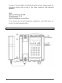
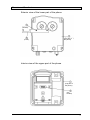
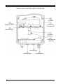
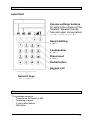
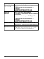
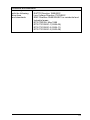
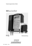
Explosion-proof telephone Operating instructions FHF BA9701-24 12/13 Foreword Our explosion-proof, weatherpoof phone offers precision, comfort, extended service life and reliability. It is programmable and it can withstand harsh environmental conditions. The phone can be used under severe conditions including seawater, high humidity, dust and it withstands strong mechanical shock in connection with explosion protection. It is fitted with an indestructible keypad made of V4A steel and an extremely robust body made of shock and impact-resistant compression moulded plastic. All components used for making this phone are resistant against lye and lubricants. The 21-part keypad optimised for "use with gloves" and made of V4A steel is easy to operate and thus meets all requirements for a modern and reliable communications device. The ExResistTel MB phone offers a reliable communication channel when connected to the public network or to PBX systems. 2 Table of contents General operating conditions ............................................................. 5 Device Overview ................................................................................ 6 Keyboard ............................................................................................ 9 Packaging Contents ........................................................................... 9 Explosion Protection - Device Description ......................................... 10 Explosion Protection - Device Construction ....................................... 11 Explosion Protection - Indicators........................................................ 14 Explosion Protection - Identification ................................................... 15 Assembly and Installation .................................................................. 16 Connection Plan ................................................................................. 17 Loop Bracket ..................................................................................... 17 Hole Pattern ...................................................................................... 18 Commissioning .................................................................................. 18 Maintenance....................................................................................... 18 Receiver Operation ........................................................................... 19 Open listening ................................................................................... 19 Hands free ......................................................................................... 19 Working with the headset .................................................................. 20 Operation ......................................................................................... 21 Receiving calls ............................................................................ 21 Call somebody ............................................................................ 21 Redial .......................................................................................... 21 Execute queries .......................................................................... 21 Change telephone configuration ................................................. 22 Signal tones ................................................................................ 22 Configuration .................................................................................... 23 Set ring tone volume ................................................................... 23 Select ring tone melody .............................................................. 23 Set receiver volume .................................................................... 23 Set speaker volume for speakers ................................................. 23 Set speaker volume for hands free ............................................. 23 Set headset volume .................................................................... 23 Save or delete telephone numbers for speed dialling buttons .... 24 Determine dialling behaviour ...................................................... 24 Save or delete line access code ................................................. 24 Determine duration of the break after dialling the line access code 24 Determine duration of the loop current disruption (flash duration) 25 Enable/disable change block ...................................................... 25 Enter PIN .................................................................................... 25 Enable/disable external speaker ................................................. 26 Restore state of delivery ............................................................. 26 State of delivery ............................................................................... 27 Technical data ................................................................................. 28 3 Directives and guidelines .................................................................. 31 Service ............................................................................................. 32 Care and maintenance ...................................................................... 32 Disposal ........................................................................................... 32 Warning and safety notes ................................................................ 32 CE certificate ..................................................................................... 34 EC Declaration of Conformity ............................................................ 35 4 General operating conditions 1. The ExResistTel MB weatherproof phone can be connected to the telephone lines of analogue exchanges. 2. The handset is fitted with a stray field coil for connecting hearing aid devices. Persons wearing a hearing aid device with an inductive receiver can directly receive the signal of the earphone. 3. The optional external speaker can be used in ringer, open listening and hands-free modes. The volume of the internal speaker is reduced when the external speaker is turned on. 4. The phone has a receiver mount with a reed contact hook switch. The handset must be placed back on the mount to end the call. A conversation is ended and a new call is started by pressing the disconnect button on the keypad (see page 9). 5. If the you do not make a selection within 2 minutes, the exchange can cut off the power supply. Then you will stop hearing the dial tone. In this case, please place back the handset, wait for 2 seconds and lift the handset again. 6. An acknowledgement tone confirms that the settings have been stored. 7. When you receive a call, the ExResistTel MB phone rings with the selected volume. 8. Changing the settings can be prevented by setting a PIN number. Forgetting the PIN number is similar to losing a key. If you forgot the PIN number, please contact our technical support service. 9. There is a warranty period of 36 months from the date of purchase. In case of any problems please contact our technical support service in Germany, Mülheim an der Ruhr: Phone number: 0208 82 68 0 · Fax: 0208 82 68 286 · E-mail: [email protected] Please use the country code if calling from outside Germany: Phone number: +49 208 82 68 0 · Fax: +49 208 82 68 286 5 In case of issues which cannot be solved by phone, please send the complete device with a copy of the sales receipt to the following address: FHF Support ExResistTel MB Gewerbeallee 15-19 D-45478 Mülheim an der Ruhr If no errors are found during the inspection, we shall issue an invoice for the processing fee. Overview of the device (Cover screws) (Top part of the phone) (Screws) (Snap-in hook) 6 Overview of the device Exterior view of the lower part of the phone (Screws) (Hook) (Top part of the phone) Interior view of the upper part of the phone (Top part of the phone) (Pin header) 7 Overview of the device Interior view of the lower part of the phone (Screws) … (Lower part of the phone) (Speaker cable) No images needed here. (Reed contact cable) (Keypad connector) (Programming interface) Keypad (Sealing plug) (Sealing plug) 8 (Cable gland) Keypad Label field Volume settings buttons for setting the volume of the handset, speaker (handsfree and open conversation) and headset during the conversation Speed dialling button Loudspeaker button Disconnect button Redial button Second call button Numeric keys Package contents The package contains: - Telephones ExResistTel MB - Operating manual - 2 sticky label panels - MB sticker 9 Explosion protection - device description The ExResistTel MB serves for making calls within operating facilities in danger of explosion in the zones: Zone 1, Zone 2, Zone 21 and Zone 22. The telephone is to be realized in the following ignition protection types: II 2G Ex e mb [ib] IIC T5 Gb II 2D Ex tb [ib] IlIC T100°C Db -25°C ≤ Ta ≤ 60°C II 2G Ex e mb [ib] IIC T6 Gb II 2D Ex tb [ib] IlIC T80°C Db -25°C ≤ Ta ≤ 40°C DMT 02 ATEX E 183 Ex e mb [ib] IIC T5 Gb Ex tb [ib] IlIC T100°C Db -25°C ≤ Ta ≤ 60°C Ex e mb [ib] IIC T6 Gb Ex tb [ib] IlIC T80°C Db -25°C ≤ Ta ≤ 40°C IECEx BVS 11.0033 The ExResistTel MB telephone is designated to analogue telephone networks. The non-secure voltage of the telephone network is led into increased security on the clamps 13 and 14 (A, B). In the call state, this voltage is switched through to the clamps 15 and 16 (Bell shunt1, Bell shunt) with increased security. The clamps 15 and 16 (Bell shunt1, Bell shunt) are designated for the connection of passive loads, e.g. a passive external, explosion protected second alarm. Furthermore, from the non-secure voltage of the analogue telephone network: • a secure listener current with clamps within the telephone casing, for the receiver connected with the telephone casing, as well as • secure circuits with clamps within the telephone casing to connect a secure headset or optionally a secure second receiver, as well as • a secure circuit with clamps within the telephone casing for the connection to a secure speaker. The headset, second receiver, external speaker and external secondary alarm accessories are not a component of the ExResistTel MB telephone, but rather can be connected as an option. 10 Explosion Protection – Device Construction The ExResistTel MB telephone has an unpainted casing made of electrical-static, conductive press plant material and a stainless steel keyboard. The casing consists of a box shaped lower part, in which a tub is integrated to hold the electronic system, as well as a curved cover with a keyboard. The cover is pressed under the medium layer of a surrounding seal with four screws on the casing lower part and forms the non-secure and secure connection space. The electronic system conductor board is located in the tub from the casing lower part, which is completely embedded in the compound. Non-secure connection clamps with increased security: From the casting, a 4-pin connection clamp series (See connection plan on page 18) comes out in increased security, to connect the non-secure telephone network (A, B), clamp 13 and 14 as well as for the connection for an optional, external, explosion protected second alarm (Bell shunt1, Bell shunt), clamp 15 an 16. 11 Secure connection clamps: From the casting, a 12-pin, secure connection clamp series (see connection plan on page 18) comes out to connect the receiver integrated in the telephone casing, clamps 1 to 4, as well as the secure accessories, clamps 5 to 12. The clamps 7 and 8 are intended for the connection of dynamic earphones, as used in second receiver and headsets. This output is therefore optionally used to connect a second receive or a headset, this means second receivers and headsets cannot be connected simultaneously as accessories. Clamp Note 1 2 3 4 Dynamic earphone connection 1 Dynamic earphone connection 2 Electret microphone connection (+) Electret microphone connection (-) 5 6 7 8 Electret microphone connection (+) Electret microphone connection (-) Dynamic earphone connection 1 Dynamic earphone connection 2 Bridges between the clamps 9 and 10 recognize the telephone as a connected headset Dynamic volume connection 1 Dynamic speaker connection 2 9 10 11 12 Usage Earphone ear piece Earpiece microphone Headset microphone Headset or second receiver earphone Headset recognition External speaker To connect the accessory, the blank plugs installed in the telephone casing are to be exchanged through suitable explosion protected cable and line guides (M20x1.5). Before the connection of the secure accessories, an evaluation of the security should be executed by the raiser corresponding with the PTB report "interconnection of non-linear and linear security circuits", PTBThEx-10, November 1999 (ISBN 3-89701-440-8), provided no system certificate is provided for the designated interconnection. The technical data for the evaluation of the security should be taken from the section "explosion protection parameters". Further information see EN60079-14 "electrical operating equipment for gas explosion endangered areas" as well as EN50281-1-1 "electrical operating equipment for usage in areas with flammable dust". When operating the device in explosion dangerous areas with flammable dust, the operator must observe EN50281-1-2 (IEC61241-1-2). 12 In order to hang up the secure accessories of the second receiver or headset, a metal clamp is designated, which is only delivered together with the headset. In order to mount the metal clamp to the telephone, two screw sockets are placed in the ground of the casing. The metal clamp has corresponding bores, which allows for a mounting on the bottom of the casing through counter sunk bolts (see device overview on page 7). Thus, the raiser must first mount this on the bottom of the casing when using the metal clamp. After this, the wall assembly occurs. Secure program interface From the cast, an 8-pin, secure connecting plug comes out (14) (see device overview on page 8). It is only used by the manufacturer for programming purposes. The connecting plug is to be left blank. Programming through the raiser is not permissible. Secure strand connection to the installed speaker From the casting, a secure 2-pin strand line (16) (see device overview on page 8), guided to the installed speaker. It is soldered under casting and on the speaker. Secure strand connection to the reed contact From the casting, a secure 2-pin strand line (17) (see device overview on page 8) led to a board, on which a magnet contact (reed contact) is found. It is soldered under casting and on the conductor board with the magnet contact. Secure keyboard connection From the casting, a secure 14-pin flat band line with connector is guided through (7) (see device overview on page This connector should be placed on the 14 pin pin in the casing cover before the device is screwed down. 13 Explosion protection – parameters 1. Non-secure power circuits 1.1 Telephone network (Clamps A/B no.: 13 – 14) Maximum input voltage Um (call voltage) AC 90 V Permissible frequency range 16...54 Hz or Maximum input voltage Um (supply voltage) DC 66 V Maximum input rated current 100 mA Maximum input short circuit current IK 35 A (In the input of this device is a fuse with a disconnect threshold of 35 A.) 1.2 External second alarm: only for the connection to passive conductors (Clamps Bell shunt1, Bell shunt no.: 15 –16) Maximum call voltage AC 90 V Frequency range 16...54 Hz or Maximum supply voltage DC 66 V 2. Secured Circuits 2.1 2.2 14 Headset (microphone) (Clamp pair HSM no.: 5 – 6) Maximum output voltage Maximum output current Maximum output rating Maximum external capacity Maximum external inductance Uo Io Po Co Lo 17 90 80 375 1,2 V mA mW nF mH Headset (earphone) or second receiver (Clamp pair HSR No.: 7 – 8) Maximum output voltage Maximum output current Maximum output rating Maximum external capacity Maximum external inductance Uo Io Po Co Lo 17 110 190 375 1,2 V mA mW nF mH 2.3 2.4 2.5 Headset (recognition) (Clamp pair HSS No.: 9 – 10) Maximum output voltage Maximum output current Maximum output rating Maximum external capacity Maximum external inductance Uo Io Po Co Lo 17 8 33 375 100 V mA mW nF mH External speaker (Clamp pair SPK No.: 11 – 12) Maximum output voltage Maximum output current Maximum output rating Maximum external capacity Maximum external inductance Uo Io Po Co Lo 6,6 250 370 22 0,3 V mA mW µF mH All secure output circuits have a linear output response curve. 3. Ambient temperature range -25°C < Ta < 60°C for the temperature class -25°C < Ta < 40°C for the temperature class Ex e mb [ib] IIC T5 Gb Ex tb [ib] IIIC T100°C Db -25°C≤Ta≤T60°C T5Ex e mb [ib] IIC T Gb T6Ex tb [ib] IIIC T80°C Db -25°C≤Ta≤T40°C Explosion protection identification DMT 02 ATEX E 183 IECEx BVS 11.0033 F-No. ................... Insp. ................ Ik 35A IP66 IK09 Art.-No. ....................... Um = AC 90V / Um = DC 66V Figure identification plate Telephone type ExResistTel MB 15 Assembly and installation The device can be installed only on a solid and vertical wall. Loosen the screws of the cover (2) (see the overview of the device on page 6 to 8) and take off the top part of the phone (1). When using the optional accessories: headset or second headset, mount the hook (10) with two screws (11) on the rear side of the lower part of the phone (In case of the above accessories, the hook and the screws and also in case of all optional accessories the cable gland is included in the respective package). Insert four screws with a head diameter of 10 to 13 cm in the opening (20) and mount the lower part of the phone (3) on the wall or a panel. Insert the phone wire through the cable gland (4) and connect it to the clamps 13 and 14 (A, B) according to the wiring plan. Only use wires with an outer diameter of 5 to 9 mm, the IP66 rating of the device cannot be otherwise guaranteed. Connecting the secondary sounder (for W conductor) (optional accessory) Remove the sealing plug (5) and screw in the M20x1.5 cable gland completely. Insert the wire of the secondary sounder through the cable gland and connect it to the clamps 15 and 16 (Bell shunt 1, Bell shunt) according to the wiring plan. Only use wires with an outer diameter of 5 to 9 mm, the IP66 rating of the device cannot be otherwise guaranteed. Connecting the speaker (optional accessory) Remove the sealing plug (6) and screw in the M20x1.5 cable gland completely. Insert the wire of the speaker through the cable gland and connect it to the clamps 11 and 12 (SPK+, SPK-) according to the wiring plan. Only use wires with an outer diameter of 5 to 9 mm, the IP66 rating of the device cannot be otherwise guaranteed. Connecting the headset (optional accessory) Remove the sealing plug (6) and screw in the M20x1.5 cable gland completely. Insert the cable with the headset socket (included in the package of the FHF headset) through the cable gland and connect it to clamps 5 to 10 (HSM+, HSM-, HSR+, HSR-, HSS1, HSS2) according to the wiring plan. Only use the cable included in the package of the headset, because the IP66 rating of the device cannot be guaranteed. Connecting the second headset (optional accessory) Remove the sealing plug (6) and screw in the M20x1.5 cable gland completely. Insert the wire of the second headset through the cable gland and connect it to the clamps 7 and 8 (HSR+, HSR-) according to the wiring plan. 16 Check the correct position of the cover seal prior to assembly. Connect the ribbon cable with the connector (7) to the pin header (8) in the upper part of the device. Mount the upper part of the phone and fasten it with four cover screws (2) to the lower part of the phone. When optional accessories are removed, close the openings created with the EEx e II certified sealing plugs. External second ringer Telephone-network lines External loudspeaker Second earpiece ye gn wh br Handset Handset Wiring diagram Support hook The support force for holding the handset is infinitely adjustable. Loosen the screws (12) and slide the snap-in hook (13). If you slide the snap-in hook together, the support force increases, if you slide them apart, the force decreases. Tighten the screws again. 17 Hole pattern Please use the following dimensions (in millimetre) for making a drilling template: The diameter of the hole depends on the screws used (max. screw diameter 8 mm) and the type of the surface (steel, wood, concrete, sheetrock etc.) and please select accordingly. Putting into service The ExResistTel MB phone is ready for operation immediately after connecting it to the network. Maintenance The ExResistTel MB phone does not contain any components requiring maintenance. 18 Handset operation If you lift the handset, the phone starts in handset mode. You can modify the handset volume for the conversation using the and buttons. For a permanent modification of the handset volume, please access the configuration of the phone (see page 24). You can switch to open listening with the button. Hold down the button and put the handset back to switch to hands-free mode. Open listening You can modify the volume for open listening using the and buttons. For a permanent modification of the speaker volume, please access the configuration of the phone (see page 24). The handset volume cannot be modified in open listening mode. You can switch to handset mode with the button. Hold down the button and put the handset back to switch to hands-free mode. Hands-free mode If you turn on the ExResistTel MB phone with the button, it starts up in hands-free mode. You can modify the speaker volume of the conversation using the and buttons. For a permanent modification of the speaker volume, please access the configuration of the phone (see page 24). You can end the conversation with the button. If you lift the handset, the phone switches to handset mode. 19 Using the headset If the headset is connected, the phone switches from open conversation to headset mode. Open conversation is therefore not possible with the headset. If you turn on the ExResistTel MB phone with the button, it starts up in headset mode. If you lift the handset in the headset mode, the handset is given priority. This means that you can listen and speak using the handset, and you can only listen with the headset. Compare the operation without and with the headset connected: Operation without the headset Operation with the headset Handset operation Handset operation with the headset - Handset is used for speaking and listening - headset is used for listening only - Speaker is turned off Open listening with the headset - Handset is used for speaking and listening - headset is used for listening only - Speaker is turned on Headset mode - Handset is placed back - headset is used for speaking and listening - Speaker is turned off Open listening Hands-free mode You can modify the headset volume of the conversation using the and buttons. For a permanent modification of the headset volume, please access the configuration of the phone (see page 24). You can end the conversation with the button. You can specify the operation of the ExResistTel MB phone after disconnecting the headset in the configuration. 20 Operation Receiving calls Calls received are indicated with acoustic signals of the built-in speaker. If the external speaker is connected and activated, the external speaker is used for acoustic signalling. Lift the handset to establish the connection with the caller. For activating the hands-free mode or headset mode press the speaker button instead. Making a call Lift the handset, and you can hear the dial tone (dial ready tone) of the public network or of the PBX network respectively. Press the speed dialling button or the redial button or use the numeric keys to select the phone number of the other party automatically or manually. Instead of lifting the handset, you can press the speaker button to make a call in open conversation or headset mode. For selecting a new phone number, you do not need to place the handset back, you can press the disconnect button. The present conversation is ended and you can hear the dial tone to select a new phone number. Redialling If you press the redial button, the phone selects the last phone number dialled after lifting the handset or pressing the speaker button. Making a second call During the conversation, you can disconnect and place the present conversation on hold to make a second call with a different party. Press the second call button and you will hear the dial tone. Dial the phone number of the second party. After ending the second call, you can return to the first call on hold by pressing the second call button again. You can also connect the two parties of the first and second call with each other: Place the handset back or press the speaker button in hands-free or headset mode. Making a second call is an additional service of the network operator or of the PBX you use. 21 Operation Changing the phone settings The phone is fitted with a programmable memory which permanently stores the settings like dialled numbers, volume settings, time data etc. These settings are adjustable to ensure that the phone can be adapted to diverse operating conditions. All adjustable settings of the phone configuration are presented in the Configuration section below. + v) Name: = n m # i) ii) 0 1 { Name} + iii) iv) 0 2 i) All modifications are made by pressing the and buttons at the same time. The setting is selected for modification with the ii) buttons, and the settings range if shown by the symbolic name iii). The additional row v) contains the list of buttons which can be used here. If you press iv) twice then the configuration is ended and the modified settings are stored in the memory. The symbolic name is enclosed with { } brackets, and 0, 1 or several buttons of the list v) can be pressed, otherwise the user can press exactly one button. Signal tones _______ Acknowledgement sound ____ Error sound PIN-Ping, Request to introduce the PIN number _ 22 Indication sound, selected speed dialling memory is not empty Configuration Setting the ringer volume + Volume:= { Volume } | | | | + | | Factory setting: 7 Settings range: 1 – 6 Selecting a ringtone + Tune:= | { Tune } | | | + | | | | | Factory setting: 0 Selection range: 0 - 9 Setting the handset volume + { Handset volume } Handset volume:= | | | | + | | Factory setting: 1 Settings range: 1 - 7 Setting the speaker volume for open listening + { Open listening volume } Open listening volume:= | | | | + | | Factory setting: 5 Settings range: 1-7 Setting the volume for hands-free operation + { Hands-free volume } Hands-free volume:= | | | | + | | Factory setting: 5 Settings range: 1 - 7 Setting the headset volume + { Headset volume } Headset volume:= | | | | + | | Factory setting: 3 Settings range: 1 - 7 23 Configuration Setting or deleting phone numbers for speed dialling + Speed dial button { Speed dial no. } + Speed dial button:= M1|M2|M3| +M1| +M2| +M3 Speed dial number:= | | | | | | | | | Factory setting: Maximum phone number length: | Memory empty 32 digits + Speed dial button + The selected speed dialling memory will be deleted. Setting the call procedure + { Call procedure } + Call procedure:= || | | | | Tone dialling procedure: Tone as long as button is pressed down Tone dialling procedure: Tone length 70 ms Tone dialling procedure: Tone length 90 ms Impulse dialling procedure: Impulse/Pause ratio 1.5:1 Impulse dialling procedure: Impulse/Pause ratio 2:1 Factory setting: 3 Storing or deleting a trunk access code + { Trunk access code } Trunk access code:= | | | | + | | | | | | | Factory setting: no trunk access code Maximum length of trunk access code: 5 digits + + The trunk access code will be deleted. Setting the length of pause after dialling a trunk access code + { Trunk access code pause } Trunk access code pause:= | | | | 1s 2s 3s 4s 5s Factory setting: 3 24 + Configuration Setting the duration of a loop current interruption (flash time) when pushing the second call button ® + { Flash time } Flash time:= | | 80 ms 120 ms 600 ms + Factory setting: 2 Activating/deactivating the change lock + PIN { change lock } + Change lock:= | Change lock deactivated, all settings can be modified Change lock activated, settings are locked Factory setting: 0 Setting the PIN number + PIN { new PIN } { new PIN } PIN:= New PIN:= | | | | | | | | | Factory setting: PIN length: + | | 0000 always 4 digits If you modify the PIN number, be careful not to forget the PIN you have set. Forgetting the PIN number is similar to losing a key. If you forgot the PIN number, please contact our technical support service. Technical support service in Germany, Mülheim an der Ruhr: Phone number 0208 82 68 0 Fax 0208 82 68 286 E-mail [email protected] Please use the country code if calling from outside Germany: Phone number +49 208 82 68 0 Fax +49 208 82 68 286 25 Configuration Activating/deactivating the external speaker + { ext. speaker } + Ext. speaker:= | External speaker deactivated External speaker activated Factory setting: 0 Restoring factory settings + PIN PIN:=OOOO + Setting the procedure when disconnecting the headset + { Optional headset } + Optional headset:= | Disconnect (hang up) if the headset is disconnected in case of headset mode activated. Maintain the connection if the headset is disconnected in case of headset mode activated. 26 Factory settings The device is set for general conditions of use to ensure that it can be used immediately after connecting it. These preliminary settings can be modified according to your personal requirements and connection conditions in the configuration settings. The following preliminary settings are included in the factory settings of the device: • • • • • • Ring tone volume Ring tone tune Speaker volume volume) Speaker volume for open listening Speaker volume for hands-free operation Headset volume Redialling Speed dialling memory Call procedure: • • • • • • • Trunk access code Dialling pause after trunk access code Flash duration Modification lock PIN External speaker: Optional headset • • • 7 (maximum) 0 1 (normal speaker 5 5 3 deleted deleted tone dialling with 90 ms tone length deleted 3 seconds 120 ms deactivated 0000 deactivated 0 27 Technical Data Attention! The information listed on pages 14 and 15 in the "explosion protection parameters" section must be observed to comply with the explosion protection. Connection data Supply voltage Supply current Ringing alternating current Tone call impedance Second call button Dialling procedure Trunk access code Dial pause after trunk access code W conductor External speaker Headset Second headset Connection terminals Housing Material Height x Width x Depth Weight 28 24 VDC up to 66 VDC 15 mADC up to 100 mADC 24 VAC up to 90 VAC (at 21...54 Hz ring tone frequency 30 VAC up to 90 VAC (at 16.6...54 Hz ring tone frequency Over 6.0 kΩ at 25 Hz and 24...90 VAC Over 4.0 kΩ at 50 Hz and 24...90 VAC Flash length can be selected from 80 ms, 120 ms and 600 ms Tone dialling and impulse dialling Tone dialling according to ITU-T Q.23. Impulse dialling at an impulse to pause ratio of 1.5:1 or 2:1. One trunk access code, maximum 5 digits 1 s up to 5 s For connecting an external secondary sounder Clamps for connecting an external speaker (optional accessory) Clamps for connecting a headset (optional accessory) Note: You can connect a headset or a second headset, but not both at the same time! Clamps for connecting a second headset (optional accessory) Note: You can connect a headset or a second headset, but not both at the same time! 2 Up to 4 mm rigid 2 Up to 2.5 mm flexible Fibreglass reinforced polyester Approx. 260 mm x 228 mm x 135 mm Approx. 5,5 kg Keypad Operating position Handset Support hook protection Handset cord - Metal keypad protected against icing - 21 keys with the appropriate inscription Vertical wall-mounted. The device can be installed only on a level surface. Integrated, adjustable support hook protection Steel-reinforced armoured cord made of stainless steel Earphone Dynamic earphone with a stray field coil for the inductive connection of hearing aid devices Mouthpiece Electret microphone Noise cancellation Over 3 dB with the integrated speaking funnel Environmental conditions Protection rating: IP66 according to EN60529 Protection against Protection rating IK09 according to EN50102 mechanical wear: Operating -25°C to +60°C temperature: Storage -25°C to +70°C according to IEC60721 temperature: Other characteristics Disconnect button Separate button Hook switch Reed contact without a mechanical hook Supply - From the analogue phone network - No additional power supply required Call-charge impulse - Electrical damping for 12 kHz and 16 kHz at the earphone of over 30 dBr related to 1 kHz lock - Impedance (at the phone connections A, B): approx. 13 kΩ ( 1 Veff ; 12 kHz ; idle state) approx. 4 kΩ (10 Veff ; 12 kHz ; idle state) approx. 2.5 kΩ ( 1 Veff ; 12 kHz ; conversation state) approx. 2.3 kΩ (10 Veff ; 12 kHz ; conversation state) approx. 11 kΩ ( 1 Veff ; 16 kHz ; idle state) approx. 4 kΩ (10 Veff ; 16 kHz ; idle state) approx. 2.5 kΩ ( 1 Veff ; 16 kHz ; conversation state) approx. 2.3 kΩ (10 Veff ; 16 kHz ; conversation state) Ring tone volume - approx. 90 dB(A) in 1 m distance at 50 VAC / 50 Hz In the deliver state setting. (The maximum volume depends also on the selected tune and the feedingconditions.) - 6 levels can be selected including muted (The ring tone volume is reduced by approx. 12 dB(A) when the optional external speaker is turned on.) 29 Ring tone tunes 10 tunes can be selected Speaker volume for - maximum volume is approx. 68 dB(A) at 1 m open listening distance - 7 levels can be selected permanently or temporarily (The speaker volume is reduced if the optional external speaker is connected.) Speaker volume for -Function with ambient noises up to approx. 68 hands-free dB(A). (With higher sound levels, it is no longer to understand the speaker in speaker operation phone mode). - maximum volume is approx. 68 dB(A) at 1 m distance - 7 levels can be selected permanently or temporarily (The speaker volume is reduced if the optional external speaker is connected.) Handset volume - Handset volume between 0 db and +12 db - adjustable in 7 levels permanently or temporarily Headset volume - adjustable in 7 levels permanently or temporarily Signal tones - Signal tone in case of successful or incorrect configuration, when requesting the PIN number and changes of data stored in the memory 30 Directives and standards Conformity - ATEX-directive 94/9/EG with the following - R&TTE Directive 1999/5/EC directives - Low Voltage Directive 73/23/EEC and standards: - EMC Directive RL89/336/EC for residential and Industrial areas - ETSI TBR 38: May 1998 - ETSI TS103021-1 (2004-05) - ETSI TS103021-2 (2004-11) - ETSI TS103021-3 (2003-08) 31 Service You acquired a modern product manufactured by FHF which was subject to a strict quality assurance process. If you have any questions concerning the phone, or in the event of a fault, even after the warranty period, please contact FHF (see page 5). Please keep the type number and item number at hand (you can find these code numbers on the rating plate). Care and Maintenance The telephone is maintenance free. However, if the phone is used in areas with heavy pollution with dust, grease, oil etc. it should be cleaned regularly. Wipe the handset and the device with a damp cleaning cloth. Attention! Never use sharp objects for cleaning. Disposal The device is disposed of as electronic waste. Plastic, metal and electronic parts are to be disposed of separately upon disassembly. The requirements concerning disposal of the country of application are to be observed. Warnings and safety instructions This is an explosion protected, weatherproof phone specifically developed for use in rough industrial conditions. Please observe the following warnings and safety instructions: 1. The phone can only be connected and operated with the specified voltage. The connecting wire shall be routed not to cause a tripping hazard. 2. The phone may only be operated under the above-mentioned environmental conditions (see chapter "Technical data"). Adverse environmental conditions, for example environmental temperature too high or too low, are not permitted because they can cause the breakdown of electronic components. 3. Care must be taken to ensure that the phone and the connecting wires etc. are not damaged. Do not use the phone if damaged. 4. The circuits of the telephone may not be grounded. 5. For the operation of the phone, legal and industrial requirements, regulations for the prevention of accidents and electrical specifications must be observed. 6. Use only original parts for repair, which were replaced professionally. Other replacement parts can cause damage, negate the explosion protection and it will void the warranty. 7. Requirements on the position of the device must be met. The device can only be mounted vertically on a flat area. 8. Power frequency magnetic fields can have a slight influence on the sound quality. Please take care to select the correct place of installation in this case. 32 9. The explosion protection type of the telephone is: II 2G Ex e mb [ib] IIC T5 Gb Ex e mb [ib] IIC T5 Gb II 2D Ex tb [ib] IlIC T100°C Db Ex tb ] IlIC T100°C Db -25°C ≤ Ta ≤ 60°C -25°C ≤ Ta ≤ 60°C II 2G Ex e mb [ib] IIC T6 Gb Ex e mb [ib] IIC T6 Gb II 2D Ex tb [ib] IlIC T80°C Db Ex tb [ib] IlIC T80°C Db -25°C ≤ Ta ≤ 40°C -25°C ≤ Ta ≤ 40°C DMT 02 ATEX E 183 IECEx BVS 11.0033 10. The telephone must have zero potential to open the device. The waiting time before opening the telephone after de-energizing the voltage is at least 2 minutes! 11. Dust must not enter the device while it is open! 12. The cover seal and the collar of the lower part of the housing required for the tightness of the housing cannot be damaged during assembly or disassembly. 13. During the commissioning of the operating equipment for use in dust, the commissioned parts should be subject to a new piece inspection. 14. The speaking funnel from the receiver consists of non-conductive plastic. It may charge up dangerously with high air speed. Thus, it is forbidden to clean the speaking funnel with compressed air. 15. A rust film can form in case of a high concentration of sulphurous gases in the air. 16. We reserve the right to modify the product for its technical development without preliminary notice. 33 CE marking The ExResistTel MB phone complies with the following directives: R&TTE Directive 1999/5/EC Low Voltage Directive 2006/95/EC ATEX Directive 94/9/EG EMC Directive 2004/108/EC RoHS Directive 2011/65/EC The CE marking is proof of conformity with the above specified directives. 34 35 Subject to alterations or errors FHF Funke + Huster Fernsig GmbH Gewerbeallee 15-19 · D-45478 Mülheim an der Ruhr Phone +49 / 208 / 82 68-0 · Fax +49 / 208 / 82 68-286 http://www.fhf.de · e-mail: [email protected]