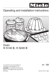
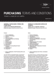
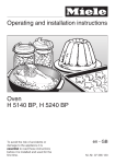
1
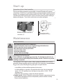
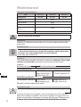
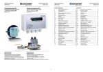
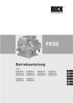
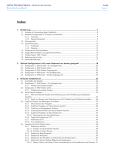
HA5
Rev. 4 - 30.05.06
Operating instructions
Types:
HA5/725-4
HA5/830-4
HA5/925-4
D
GB
F
E
I
1
Foreword
Dear Customer,
Bock compressors are top-quality, reliable, service-friendly quality products. Please comply with the
following operating and maintenance instructions so that you can benefit from all advantages to the
full and use your refrigerating system throughout its entire service life. If you have any questions about
installation, operation and accessories, please contact our technical service or your refrigerating system wholesale dealer or our representative. The Bock service team is available by phone under +49
7022 9454-0, by e-mail under [email protected] or on the internet under www.bock.de. In addition, for
German speaking countries we have set up a toll-free hotline under 00 800 / 800 000 88 from Monday
to Saturday between 8 a.m. and 9 p.m. Any suggestions you may have regarding the on-going development of our compressor, equipment and parts programme are welcome at any time.
Please read the information summarised for you in this manual before starting work.
It contains important instructions for safety, installation, initial commisioning and handPleaseon
read
the information
for you in this
ling. In addition you will find information
maintenance,
sparesummarised
parts and accessories.
manual before starting work.
Some instructions are identified by special symbols with the following meaning:
It contains important instructions for safety, installation, initial
WARNING! This symbol is used to indicate that inaccurate compliance or total
commissioning and handling. In addition you will find informafailure to comply with the instructions could cause injury to persons or damage
tion on maintenance, spare parts and accessories.
to the comperssor or refrigerating machine.
Some instructions are identified by special symbols with the
DANGER! This symbol refers
to instructions
following
meaning: for avoiding direct serve dangers to
persons.
WARNING! This symbol is used to indicate
The high quality standart of Bock compressors is guaranteed also by on-going furtherdevelopment
DANGER! This symbol refers to instructions for
of machine, features and accessories. This could possible results in non conformities between this
avoiding direct severe dangers to persons or
present manual and your compressor. Please understand tha it is not possible for any claims to be
plant by electrical current.
derived from the details, illstrations and descriptions.
This symbol indicates important additional
Your team at
instructions which you should observe during
Bock Kältemaschinen GmbH
- Subject to modification your work.
D
GB
F
Bock Kältemaschinen GmbH
E
Postfach 11 61
D-72632 Frickenhausen
I
Benzstr. 7
D-72636 Frickenhausen
Fon: +49 7022 9454-0
Fax: +49 7022 9454-137
[email protected]
www.bock.de
2
The high quality standard of Bock compressors is guaranteed
also by on-going further development of machine, features
and accessories. This could possibly result in nonconformities
between this present manual and your compressor. Please
understand that it is not possible for any claims to be derived
from the details, illustrations and descriptions.
Your team at
Bock Kältemaschinen GmbH
- Subject to modifications -
Rev. 4 - 30.05.06
that inaccurate compliance or total failure to
DANGER! This symbol refers to instrucion for avoiding direct serve dangers to
comply with the instructions could cause injury
persons or plant by electrical current.
to persons or damage to the compressor or
refrigerating machine
This symbol indicates important additional instructions which you should
DANGER! This symbol refers to instructions for
observe during your work.
avoiding direct severe dangers to persons.
Rev. 4 - 30.05.06
Contents
Page
Safety instructions
4
Product description
5
Use as intended
Short description
Main and functional parts
Name plate
Type code
Areas of application
7
Refrigerant
Oil filling
Limits of application diagrams
Installation
9
Erection
Pipe connections
Pipes
Shutoff valves
Electrical system
12
General instructions
Standad motor, designed for direct or part winding start
Maine line wiring diagram for part winding start with standard motor
Special Motor version for direct or star delta starting
Maine line diagram for star delta starting with special motor
Electronic trigger MP 10
Connection of the release unit MP 10
Function test of the electronic trigger MP 10
Information for contactor and motor contactor selection
Oil sump heater
Ventilator motor
Start-up
19
Preparations for start-up
Pressure strength test
Tightness test
Evacuation
Filling with refrigerant
Start up
Liquid sluggings
Connection of the oil level controller
Maintenance
21
Safety instructions
Spare parts recommendation
Screwed unions
Lubricants
Decommissioning
Technical data
23
Dimensions and connections
24
Conformity and manufacturer‘s declaration
26
D
GB
F
E
I
3
Safety instructions
The
refrigerating
named in the title
for installation
Die Bock
im Titel
genanntencompressors
Bock-Kältemittelverdichter
sindare
fürintended
den Einbau
in Maschinen
in(innerhalb
machinesder
(within
the EU den
according
to EU directive
98/37/EC
Machinery Directive,
EU gemäß
EU-Richtlinien
98/37/EG
-Maschinenrichtlinie-,
97/23/
97/23/EC
Pressure
Equipment
Directive
and
73/23/EC
Low
Voltage
Directive).
Initial
EG
–Druckgeräterichtlinieund
73/23/EG
-Niederspannungsrichtlinie-)
bestimmt.
The Bock refrigerating compressors named in the title are intended for installation Die
commissioning
isist
only
when
the
compressor
has
beendieser
installed
according
to
Inbetriebnahme
nurallowed
zulässig,
wenn
Verdichter
gemäß
Anleitung
eingebaut
in
machines (within
the
EU
according
todie
EU
directive 98/37/EC
Machinery
Directive,
these
instructions
and
the whole
machine
inintegriert
which
it sind,
is Low
integrated
has
been tested
and
wurden
und
die Gesamtanlage,
in die sie
den
gesetzlichen
Vorschriften
97/23/EC
Pressure
Equipment
Directive
and
73/23/EC
Voltage
Directive).
Initial
accepted
according
to allowed
the
entsprechend
geprüft
undstatutory
abgenommen
wurde.
commissioning
is only
whenregulations.
the compressor
has been installed according to
these instructions and the whole machine in which it is integrated has been tested and
Bock
refrigerating
been
state-of-the-art
Bock-Kältemittelverdichter
sindhave
nach
dem designed
neuesten to
Stand
der Technikengineering.
konzipiert.
accepted
accordingcompressors
to the statutory
regulations.
Safety
for the user
is given
particular
priority
during the
design stage.
However,
it is
Die Sicherheit
für den
Anwender
ist als
besonderer
Schwerpunkt
in der
Konstruktion
always
possible
for
the
refrigerating
machine
and
operation
thereof
to
pose
unavoidable
berücksichtigt.
Von
Kältemittelverdichtern
und
deren
Betrieb
können
jedoch
unverBock refrigerating compressors have been designed to state-of-the-art engineering.
residual
Thisisisgiven
why
these
instructions
bedesign
observed
carefully
meidbare
Restgefahren
ausgehen.
Deshalb
istmust
diethe
vorliegende
Anleitung
von
Safety
forrisks.
the
user
particular
priority during
stage.
However,by
it every
isjeder
person
working
at
the
compressor.
Person,
die
am
Verdichter
arbeitet,
sorgfältig
zu
beachten.
always possible for the refrigerating machine and operation thereof to pose unavoidable
documentation means that they are capable of assessing the work to be carried out and
Safety
instructions
Safety
instructions
Sicherheitshinweise
detecting
any
possible dangers.
Note!
Refrigeration
compressors
are
pressure
andzulässig!
require
Any
handling
of the
compressor
is machines
permissible
only by
by
skilled personnel!
Jeglicher
Umgang
mit
dem Verdichter
ist nurloaded
durch
Fachpersonal
special
caution
and safety
care inregulations,
the handling.accident
Safety
instructions
Observe
national
prevention regulations,allgemein
Nationale
Sicherheitsbestimmungen,
Unfallverhütungsvorschriften,
generally
recognized
technical
as spezifi
well assche
specifi
regulations
anerkannte
technischen
Regelnrules
sowie
(EN(EN
378,378,
EN
Any
handling
of the compressor
is
permissible
onlyVorschriften
byc skilled
personnel!
EN
60204,
EN
60335
etc.).
60204,
EN
60335,
IEC/EN
60079-14
u.a.)
beachten.
Observe national safety regulations, accident prevention regulations,
Carry
compressors
only
with hoists
with
suffi
lifting
power.
Verdichter
nur mit Hebezeugen
mit ausreichender
Tragkraft
befördern.
generally
recognized
technical
rules
as well
ascient
specifi
c regulations
(EN 378,
Operate
compressors
only in refrigeration
plants with
approvedbetreiben.
refrigerants.
Verdichter
nur60335
in Kälteanlagen
mit freigegebenen
Kältemitteln
EN
60204,
EN
etc.).
Do
notcompressors
exceed
permissible
operating
pressure
– even
for überschreiten.
testing
Zulässigen
Betriebsdruck
- auch
zu with
Prüfzwecken
- lifting
nicht
Carry
only with
hoists
sufficient
power. purposes.
Caution!
Compressors
are
fi
lled
with
protective
gas
ex
works
3 bar
Vorsicht!
Verdichter
ab
Werk
sind
Schutzgas
befüllt
(ca.
3
bar(approx.
Stickstoff).
Operate compressors only in refrigeration plants with approved
refrigerants.
nitrogen).
Avoid
possible
injuries
to
skin
and
eyes!
Wear
goggles!
Relieve
Mögliche
Verletzungen
an
Haut
und
Augen
vermeiden!
Schutzbrille
tragen!
Do not exceed permissible operating pressure – even for testing purposes.
pressure
of vor
compressors
connection
to druckentlasten!
the
system!
Verdichter
Anschluss
an
daswith
Kältesystem
Caution!
Compressors
arebefore
filled
protective
gasrefrigeration
ex works (approx.
3 bar
Before
start-up
check
compressor
for
transport
damage.
Montagearbeiten
nur
vornehmen,
wenn
keine
Beschädigungen,
nitrogen). Avoid possible injuries to skin and eyes! Wear goggles!UndichtigRelieve
Before
check
thatbefore
all components
mounted
bysind.
the user are
installed
keiten start-up
und/oder
Korrosionserscheinungen
erkennbar
pressure
of compressors
connection
to the refrigeration
system!
correctly
and am
connected
pressure-tight
with theWartungsvorschriften
compressor (pipes, plugs,
Reparaturen
Verdichter
sind nicht
beachten!
Before
start-up
check
compressor
for zulässig.
transport
damage.
union
nuts,
replaced
components
etc.).
Vor Inbetriebnahme
alle
vom Anwender
Before
start-up
checkprüfen,
that allob
components
mountedmontierten
by the userBauteile
are installed
Before
start-up
evacuate pressure-tight
the refrigeration
plant
compressor
carefully
fachgerecht
und
druckfest mit
dem
Verdichter
verbunden
sindand
correctly
andangebracht
connected
with
thewith
compressor
(pipes,
plugs,
then
charge
with Stopfen,
refrigerant.
(Rohrleitungen,
Überwurfmuttern,
ersetzte Bauteile usw.).
union
nuts, replaced
components
etc.).
Open
discharge
and suction
before
starting
the compressor.
Vor Inbetriebnahme
Kälteanlage
mitvalves
Verdichter
sorgfältig
evakuieren
und and
Before
start-up evacuate
the shutoff
refrigeration
plant
with
compressor
carefully
Do
not
start
the
compressor
in
vacuum!
Operate
only
with
refrigerants
charge.
anschließend
mit
Kältemittel
befüllen.
then charge with refrigerant.
Corresponding
to
the
conditions
of
use,
surface
temperatures
of
more
Vor
Start
des
Verdichters
Druckund
Saugabsperrventile
öffnen.
Open discharge and suction shutoff valves before starting the compressor.than
100
°C on
the
discharge
side and
below
0Operate
°C
theonly
suction
sidebetreiben.
can be reached.
Verdichter
nicht
im Vakuum
starten!
Nur
beionbefüllter
Anlage
Do
not
start
the
compressor
in
vacuum!
with
refrigerants
charge.
Entsprechend
den
Einsatzbedingungen
können
Oberfl
ächentemperaturen
Corresponding to the conditions of use, surface temperatures of more than
von°C
über
100discharge
°C auf derside
Druckseite
und0 unter
°Csuction
auf der side
Saugseite
100
on the
and below
°C on0the
can beerreicht
reached.
werden.
D
GB
F
E
I
4
Rev. 4 - 30.05.06
residual risks. This is why these instructions must be observed carefully by every
Work
onworking
the
may only
carried
out byvorgenommen
persons whose
technical
Arbeiten
amcompressor
Verdichter
dürfen
nurbe
von
Personen
werden,
die trainaufgrund
person
at the compressor.
ing,
and experience
together
with their
of pertinent
and
ihrerskills
fachlichen
Ausbildung,
Kenntnisse
undknowledge
Erfahrungen
sowie derregulations
einschlägigen
documentation
means
that
they
are
capable
of
assessing
the
work
to
be
carried
out and
Bestimmungen
die
auszuführenden
Arbeiten
beurteilen
und
mögliche
Gefahren
Work on the compressor may only be carried out by persons whose technical traindetecting
any
possible
dangers.
erkennen
können.
ing, skills and experience together with their knowledge of pertinent regulations and
Product description
Use as intended
This operating manual describes the compressor named in the title in the standard
version. Bock refrigerant compressors are intended for use in refrigeration plants using
the refrigerants stated below and under compliance with the operating limits. Any other
use of the compressor is not permitted!
WARNING! Do not use in explosion-risk environments!
Short description
Half-hermetic four-cylinder
four-cylinder reciprocating
reciprocatingcompressor
compressorwith
withair
oilcooled
pump lubrication
● Semihermetic
drive
● Air
cooledgas
drive
motor
Suction
cooled
drive motor.
motor
● Driving
motor
at the compressor
statorhigh
flanged
on.
Compact
dimensions,
quiet running,
efficiency.
● Particularly for the freezing with air-cooled engine and direct sucking in at the cylinder.
Main function parts
Terminal box
Transport eyelet
Suction shut-off
valve
Discharge
shut-off
valve
Connection
for capacity
regulator
Rev. 4 - 30.05.06
Oil pump
Oil sump
heater
Valve plate
GB
Connection for heat
protection thermostat
Oil sight glass
Oil drain plug /
oil filter
D
Oil filler plug
F
E
Connection Oil
level regulator
I
5
Product description
Name plate (example)
6
7
8
9
10
11
12
13
1
2
3
4
5
1
2
3
4
Type designation
Machine number Maximum operating current
Start-up current (rotor blocked)
Y: part winding 1
YY: part winding 1 and 2
5 ND (LP): max. admissible stop period pressure
intake side
ND (HP): max. admissible working pressure
high pressure side
6
7
8
9
10
11
12
13
Voltage, switching, frequency
Rated speed
50 Hz
Theoretical volume flow rate
Voltage, switching, frequency
Rated speed
60 Hz
Theoretical volume flow rate
Oil grade filled by the manufacturer
Protection terminal box
Electrical accessories can change
the IP safety class system!
Note limits of application diagramms!
Type code (example)
HA X 5 / 945 - 4
ester oil filling2)
D
size
GB
F
swept volume
E
motor pole number
I
HA= Hermetic-Air-cooled for deep freezing
X= Ester oil filling (HFC refrigerant), e.g. R404A, R507
1)
2)
6
Rev. 4 - 30.05.06
series1)
Areas of Application
Rev. 4 - 30.05.06
Refrigerant
Kältemittel
(H)FCKW / (H)CFC:
R22
HFKW / HFC:
R404A/R507
Oil
filling
Ölfüllung
The compressors are filled with the following oil grades in the factory:
Werkseitig werden die Verdichter mit folgenden Ölsorten befüllt:
- for R22
FUCHS Reniso SP 46
für R22:
FUCHS Reniso SP 46;
- for R404A/R507
FUCHS Reniso Triton SE 55
für R404A/R507:
FUCHS Reniso Triton SE 55.
Verdichter
mit Esterölfüllung
(FUCHS
Triton SE
55) sind mitsee
einem
X in der
● We
recommend
the above oil
gradesReniso
for refilling.
Alternatives:
the lubricant
Typbezeichnung
table
page 22. gekennzeichnet (z.B. HAX34P / 315-4)
Zur Nachfüllung empfehlen wir die o.a. Ölsorten zu verwenden. Alternativen: siehe
Limits
of application
diagrams
Auszug
aus der Bock-Schmierstofftabelle
S. 18.
●
It
is
possible
to
operate
the
compressor
within the operating limits shown
Einsatzgrenzen
in the diagrams. Please note the significance of the shaded areas. Thresholds
Der
Betrieb
Verdichters
ist im Bereich
der gezeigten
Diagramme
should
not des
be selected
as design
or continuous
operating
points.zulässig. Die
Einsatzgrenzen
sind
einzuhalten.
Die
maximale
Verdichtungsendtemperatur
von
- Max. permissible end temperature of the compressor: 140°C
140
°C
darf
nicht
überschritten
werden.
Einsatz
in
erweiterten
Bereichen
nur
mit
- Max. permissible switching frequency: 12x /h
reduzierter
Sauggastemperatur.
- A minimum
running time of 3 min. steady-state condition (continuous operaWir
empfehlen:
tion)
must be achieved.
- Verwendung eines Wärmeschutzthermostates (Zubehör)
Nur thermisch
hochstabile
Öleregulator
verwenden (siehe Schmierstofftabelle)
●- With
enterprise
with output
--Dauerbetrieb
imsometimes
Grenzbereich
vermeiden.
in the frontier
reduction
and/or individual attitude of the suction
- Beim
Einsatz
von
Leistungsreglern
gas overheating necessarily. Sauggasüberhitzung u.U. reduzieren,
individuelle Einstellung erforderlich.
Bei operation
Betrieb mitwith
Frequenzumformer
beachten: Durch das Erreichen der maximal
●-For
frequency converter
zulässigen
Stromaufnahme
des
Antriebsmotors
sind die Einsatzgrenzen
eingeschränkt.
- Achieving the max. permissible power consumption
of the drive motor
can
Dierestrict
maximal
zulässige
Schalthäufi
gkeit
des
Verdichters
(8
Schaltungen/h)
nicht überthe operating limits.
schreiten! Beharrungszustand (kontinuierliche Betriebsbedingung) der Anlage muss
erreicht
Mindestlaufzeit
von
3 min.there
nichtisunterschreiten.
● During werden.
operation
in the vacuum
range,
a danger of air entering on the
Beim
Betrieb
im
Unterdruckbereich
besteht
die Gefahr
von
Lufteintritt
auf
suction side. This can cause chemical reactions,
pressure
rise
in the conden
der and
Saugseite.
Dadurch
können chemische
Reaktionen,
imentry
ser
an excessive
compressed-gas
temperature.
AvoidDruckanstieg
absolutely any
Verfl
of
air.üssiger und eine überhöhte Druckgastemperatur sowie die Verschiebung
der Kältemittelzündgrenze in den kritischen Bereich hervorgerufen werden.
Lufteintritt unbedingt vermeiden!
D
GB
F
E
I
7
Areas of application
R404A
R507
Unlimited application range
D
Reduced suction gas
temperature
GB
F
evaporation temperature (°C)
condensing temperature (°C)
suction gas overheating (K)
suction gas temperature (°C)
Design for other
areas on request
E
I
Max. permissible operating
pressure (HP): 28 bar
8
Rev. 4 - 30.05.06
R22
Installation
Warning! Compressors are filled with protective gas ex works (approx. 3 bar
nitrogen!
● Leave protective gas filling in the compressor up to evacuation.
● Do not open shutoff valves up to evacuation.
● Absolutely avoid entry of air!
Pipe
connections
Erection
Aufstellung
The pressure and suction shutoff valves have graduated
inside diameters, so that pipes in the customary millimeter
● and
Use
transport
eyelet.
Hebezeug
verwenden!
Transportöse
benutzen.
inch
dimensions
can be used. The pipe will be
● immersed
Do
notmanuell
lift manually!
Nicht
moreheben!
or less deeply according to dimension.
● The
Use
lifting gear!
Transportöse
benutzen.
Hebezeug
verwenden!
connection
diameters of the shutoff valves are designed
for the maximum compressor output. The actually required
pipe cross-section must be adapted to the actually
Fig.: schematic
refrigeration capacity. The same applies for non-return
●valves.
Erect
on a flat
frame oder
with sufficient
load-bearAufstellung
aufsurface
ebenerorFläche
Rahmen mit
ausreiCaution when soldering! ing
ability.Tragkraft.
Only erect
on a slant nur
in consultation
with the
chender
Schräglage
nach Rücksprache.
Remove screw connections
from the valvevorzugsweise
for soldering. auf Schwingungsdämpfer.
manufacturer.
Einzelverdichter
Do not overheat the valve.
● Single
preferably ongrundsätzlich
vibration damper.
Duplex-compressor
und Verbundschaltung
starr.
Cool the valve body during
and after
● Duplex
and soldering.
compound connection basically rigid.
Rev. 4 - 30.05.06
● Ensure
there is
sufficientfürspace
for maintenance
work
Ausreichend
Freiraum
Wartungsarbeiten
vorsehen.
● Ensure
there isMaschinenraumbelüftung
sufficient ventilation in thevorsehen.
machine room.
Ausreichende
Do
in a Atmosphäre,
corrosive
dust,oder
vapor
or Nicht
inoperate
korrosiver
brennWarning! Compressors●are
finot
lled
with protective
gasatmosphere,
exStaub,
worksDampf
(approx.
3 bar
flammable
environment.
barer Umgebung
betreiben.
nitrogen!
● Leave protective gas filling in the compressor up to evacuation.
● Do not open shutoff valves up to evacuation.
● Absolutely avoid entry of air!
D
GB
F
Pipe connections
Fig.: schematic
E
The pressure and suction shutoff valves have graduated
inside diameters, so that pipes in the customary millimeter
and inch dimensions can be used. The pipe will be
immersed more or less deeply according to dimension.
The connection diameters of the shutoff valves are designed
for the maximum compressor output. The actually required
pipe cross-section must be adapted to the actually
refrigeration capacity. The same applies for non-return
valves.
Caution when soldering!
Remove screw connections from the valve for soldering.
Do not overheat the valve.
Cool the valve body during and after soldering.
I
9
and
inch
dimensions
candeeply
be used.
Thecustomary
pipe
will be
immersed
more orsoless
according
to dimension.
inside
diameters,
that
pipes
in the
millimeter
immersed
more
or
deeply
to
immersed
more diameters
or less
less
according
to dimension.
dimension.
The
connection
of used.
theaccording
shutoff
valves
and
inch
dimensions
candeeply
be
The pipe
willare
be designed
The
connection
diameters
of
shutoff
are
designed
The
connection
of the
the
shutoff
valves
are required
designed
for
the
maximum
output.
Thevalves
immersed
more diameters
orcompressor
less deeply
according
toactually
dimension.
for
the
maximum
compressor
output.
The
actually
required
for
the
maximum
compressor
output.
The
actually
required
pipe
cross-section
must
be
adapted
to
the
actually
The
connection
diameters
of
the
shutoff
valves
are
designed
Fig.: schematic
pipe
cross-section
must
be
adapted
to
the
Fig.:
pipe
must
besame
adapted
to actually
the
actually
refrigeration
capacity.
The
applies
foractually
non-return
for
thecross-section
maximum
compressor
output.
The
required
Fig.: schematic
schematic
refrigeration
capacity.
The
same
applies
for
non-return
refrigeration
capacity.
The
same
applies
for
non-return
valves.
pipe cross-section must be adapted to the actually
Fig.: schematic
valves.
valves.
Caution when soldering! refrigeration
capacity. The same applies for non-return
Caution
when
soldering!
Caution
when
soldering!
Remove
screw
connections
from the valve for soldering.
valves.
Remove
screw
connections
Remove
screw
connections
from the
the valve
valve for
for soldering.
soldering.
Do
notwhen
overheat
the valve. from
Caution
soldering!
Do
not
overheat
the
valve.
Do
not
overheat
the
valve.
Cool
the
valve
body
during
and
after
soldering.
Remove screw connections from the valve for soldering.
Cool
valve
during
Coolnotthe
theoverheat
valve body
body
during and
and after
after soldering.
soldering.
Do
the valve.
Cool the valve body during and after soldering.
Pipes
Installation
Pipes and system components must be clean and dry inside and free of scales, metal
chippings, and coats of rust and phosphate. Only use hermetically sealed parts.
Lay pipes correctly. Avoid strong vibrations because of the risk of cracks and breaks.
Provide suitable fixed points and/or vibration compensators as required.
Guarantee a correct oil return.
Keep pressure losses to an absolute minimum.
A proper run of the suction and discharge line immediately after the compressor is of great importance for the system´s smooth running and freedom from
vibration.
D
As short as
possible
GB
F
E
I
10
Stable
fixed point
Rev. 4 - 30.05.06
Improperly installed pipes can cause cracks and tears, which results in refrigerant
loss.
A rule of thumb:
Always lay the first pipe section starting from the compressor downward and
parallel to the drive shaft.
Installation
Shut- off valves
Attention! Comply with the safety instructions on page 9!
Before opening or closing the shut-off valve, turn the valve spindle seal approx. ¼ of a
turn counter-clockwise. After activating the shut-off valve, tighten the valve spindle seal
again clockwise.
tighten
Valve spindle seal
Valve spindle seal
loosen
lösen
tighten
anziehen
loosen
Fig. schematic
Fig.: schematic
Mode
of operation
the screw-down
service connections
Funktionsweise
derofabsperrbaren
Serviceanschlüsse
Rev. 4 - 30.05.06
Position
Stellung A
Opening
theAbsperrventils
shutoff
Öffnen des
valve:
Spindel 1 nach links (gegen den
Turn
the spindlebis
to zum
the Anschlag
Uhrzeigersinn)
left
(counterclockwise)
aufdrehen.
up to the stop.
Absperrventil ist voll geöffnet /
Shufoff valve fully
Service-Anschluss 2 geschlossen
opened, service connec(Stellung A).
tion closed.
Opening
theServiceservice
Öffnen des
connection:
anschlusses (2)
1 - 1 turn
Turn
spindle
Spindel
1 etwa/2 ½
bis 1 Umdreto
the nach
right.rechts (in Uhrzeigerhung
Service
richtung)connection
drehen.
opened, shutoff valve
Service-Anschluss 2 ist jetzt
opened.
geöffnet, das Absperrventil ist
ebenfalls geöffnet (Stellung B).
Pipe
connection
Rohranschluss
Compressor
Verdichter
Position
Stellung B
Pipe
connection
Rohranschluss
D
GB
F
E
Compressor
Verdichter
I
Fig. schematic
Der Anschluss 3 ist für Sicherheitseinrichtungen vorgesehen und nicht absperrbar
Connection 3 is intended for safeguard systems an cannot be shut-off.
11
Electrical system
Electrical connection
connections
Electrical
Warning! High voltage! Perform work only with the electrical installation
disconnected from the power supply!
Make connection of the compressor motor according to the circuit diagram (see
inside of terminal box). Comply with local safety regulations for electrical work and
the safety standards EN 60204, EN 60335 when connecting.
For cable lead-through at the terminal box use suitable cable screw connections in
correct protective version (see name plate). Use strain relief. Avoid abrasion points on
cables.
Motor contactors, feed lines and fuses are to be rated according to the maximum operating current (see compressor nameplate).
Compare the details for voltage and frequency on the nameplate with the details for
the electricity mains supply. The motor may only be connected up when these
details correspond.
Serienmotor,
Ausführung
für direct
Direkt-oroder
Standad
motor,
designed for
partTeilwicklungsstart
winding start
Designation
thedem
name
plate
Bezeichnungonauf
Typschild
Designation
on the
terminal box
Aufkleber auf
Klemmenkasten
Y / YY
Verdichter mit dieser
für Direktoder
Compressors
markedKennzeichnung
in this way are sind
suitable
for direct
or Teilwicklungsstart
part winding start.geeignet.
The motor
Die Motorwicklung
ist intwo
zwei
Teilepart
unterteilt:
66 winding
% und Teilwicklung
2
winding
is divided into
parts:
windingTeilwicklung
1 = 66% and1 =part
2 = 33%. This
= 33 %. devision
Diese Wicklungsaufteilung
bewirkt
beim
Teilwicklungsstart
winding
reduces the start-up
current
during
a part winding eine
start to approx. 65%
Anlaufstromreduzierung
auf ca. 65% des Wertes bei Direktstart.
of
the value for a direct start.
In
the factory,
the Motor
motor für
is switched
for(YY)
directgeschaltet.
starting (YY).
For part
winding start (Y/YY),
Werkseitig
ist der
Direktstart
Für den
Teilwicklungsstart
remove
the die
bridges
and zu
connect
the motor
feed
cable according
to the
circuit diagram.
Y / YY sind
Brücken
entfernen
und die
Motorzuleitung
gemäß
Schaltschema
anzuschließen:
D
400
400 VV
GB
Direktstart
direct
start YY
Direktstart
YY
F
E
I
12
part
winding start Y/YY
Teilwicklungsstart
Y/YY
Teilwicklungsstart
Y/YY
L1
L1
L2
L2
L3
L3
V2
2U1
U2
2V1
W2
2W1
V2
2U1
U2
2V1
W2
2W1
W1
1U1
V1
1V1
U1
1W1
W1
1U1
V1
1V1
U1
1W1
L1
L1
L2
L2
L3
L3
L1
L1
L2
L2
L3
L3
WARNUNG!
Nichtbeachten führt zu gegenläufigen Drehfeldern und hat Motorschaden zur Folge.
Nach Anlauf des Motors über Teilwicklung 1 muß nach maximal einer Sekunde
Rev. 4 - 30.05.06
Mechanical
start unloader
with bypass
is not required.
Eine mechanische
Anlaufentlastung
mitsolenoid
Bypass-Magnetventil
wird nicht benötigt.
W1
V1
U1
W1
V1
U1
L1
L2
L3
L1
L2
L3
Electrical system
WARNING!
WARNUNG!
Failure
to comply
results
in reversed fields
of rotation
and
cause motorzur
Nichtbeachten
führt
zu gegenläufugen
Drehfeldern
und
hatcan
Motorschaden
damage.
AfterAnlauf
the motor
has started
with part winding
partmaximal
winding einer
2 must
Folge. Nach
des Motors
überup
Teilwicklung
1 muss 1,
nach
be
switched
on after max. 1 second
delay.2 Failure
to complywerden.
can be detrimental to
Sekunde
Verzögerungszeit
Teilwicklung
dazugeschaltet
the
service life of
the die
motor.
Nichtbeachten
kann
Lebensdauer des Motors beeinträchtigen.
Prinzipschaltplan
Teilwicklungsanlauf
mit
Serienmotor
Prinzipschaltplan
für
Teilwicklungsanlauf
mit
Serienmotor
Main
line wiring für
diagram
for part winding
start
with standard motor
66%
33%
R2
Rev. 4 - 30.05.06
66%
33%
CAUTION!
ACHTUNG! Es ist unbedingt zu beachten, daß die Spannungsversorgung über
Ensure
thatWicklung
power is supplied
via K1
to winding
1 (66%)
(1U1 / 1V1 / 1W1) and via
den K1 auf
1 (66 %) (1U1
/ 1V1
/ 1W1) und
die Spannungsversorgung
K2
toK2
winding
2 (33%) 2(2U1
2V1
/ 2W1).
motor
contactors
(K1/K2) are (K1
each/ to
über
auf Wicklung
(33 /%)
(2U1
/ 2V1The
/ 2W1)
erfolgt.
Die Motorschütze
be
approx.
70%70of%the
max.
operating
current.auszulegen.
K2)rated
sind for
jeweils
auf ca.
vom
max.
Betriebsstrom
forPTC
PTCFühler
sensor
1-2 Connections
Anschlüsse für
sensor
motor winding
R1 PTC
Kaltleiter
(PTC-Fühler)
MotorR2 Heat
protection thermostat (PTC
wicklung
Heat
protection thermostat
R2 sensor)
Wärmeschutzthermostat
F1 2(PTC-Fühler)
motorsensor)
safety switches
(PTC
(66%:33%
of IAswitches
total
22motor
safety
F1
Motorschutzschalter
F2 Fuse
(66%:33%
IA
total)
Ges.)
(66 %control
: 33 of%power
von
IAcircuit
F3
Safety
chain
(high/low
pressure
F2 Fuse
Sicherung
Steuerstromkreis
control
power circuit
monitoring)
chain (high/low
F3 Safety
Sicherheitskette
F4 Oil
differential
pressure controller
pressure
monitoring)
(Hoch-/Niederdrucküberw.)
C1 Operating condenser
fan
B1 Öldifferenzdruckwächter
Enabling switch (thermostat)
F4
K1
Mains contactor (part
winding 1)
B1 Freigabeschalter
(Thermostat)
K2
Mains contactor
( part winding
K1 Netzschütz
(Teilwicklung
1) 2)
K1T
Delay relay (Teilwicklung
max. 1s
K2 Netzschütz
2)
A1 Trigger
unit MP10 max. 1s
K1T Verzögerungsrelais
Q1
Main switch MP 10
A1 Auslösegerät
S1 Hauptschalter
Switch control voltage
Q1
M1 Schalter
Compressor
motor
S1
Steuerspannung
M2 Verdichtermotor
Ventilator motor
M1
D D
GB
GB
F F
E E
I I
13
Electrical system
Speciale Motor version for direct or star delta starting
Sondermotor: Ausführung für Direkt- oder Stern-Dreieck-Anlauf
Mechanical start unloader with bypass solenoid (accessories) is requiered for star
Für den
Stern-Dreieck-Anlauf ist eine mechanische Anlaufentlastung mit Bypassdelta
starting.
Magnetventil (Zubehör) erforderlich.
Designation on the yellow label on the
Aufkleberterminal
auf Klemmenkasten
box
Designation on the nameplate
Bezeichnung auf dem Typschild
∆/Y
Compressors
with thisistcode
suitable in the voltage
range
(230 V) for start delta
Stern-Dreieck-Anlauf
nur are
im Spannungsbereich
∆ (230
V) ∆
möglich.
starting.
Beispiel:Example:
230 V ∆
direct
start
Direktstart
400 V Y
star delta start
Stern-Dreieck-Start
L2
L3
L1
L3
L2
only
direct start
nur Direktstart
U2
V2
W2
W2
V2
U2
V2
W2
W2
V2
U2
V2
W2
U1
W1
V1
W1
U1
U1
W1
V1
W1
U1
U1
W1
V1
W1
U1
L1
L3
L2
L3
L1
L3
L1
L2
L1
L3
L1
L3
L2
L3
L1
Rev. 4 - 30.05.06
W2
V2
D
GB
F
09791-07.06-DGbFEI
E
I
14
Electrical system
Maine
line diagramfür
forStern-Dreieck-Anlauf
star delta starting with
special
motor
motor
Prinzipschaltplan
mitspeciale
Sondermotor
Prinzipschaltplan für Stern-Dreieck-Anlauf mit Sondermotor
Prinzipschaltplan für Stern-Dreieck-Anlauf mit Sondermotor
R2
09791-07.06-DGbFEI
Rev. 4 - 30.05.06
Y1
Connections
for
PTC
sensor
Anschlüsse
PTC
Fühler
1-21-2Anschlüsse
fürfür
PTC
Fühler
PTC
sensor
motor
winding
R1
Kaltleiter
(PTC-Fühler)
Motorwicklung
1-2
Anschlüsse
für
PTC
Fühler
R1 Kaltleiter (PTC-Fühler) Motorwicklung
Heat
protection
thermostat
R2
Wärmeschutzthermostat
(PTCR1
Kaltleiter
(PTC-Fühler)
Motorwicklung
R2 Wärmeschutzthermostat (PTC(PTC
Fühler)sensor)
Fühler)
R2
Wärmeschutzthermostat
(PTCFühler)
Safety
device load Laststromkreis
stabilisation circuit
F1 Schutzeinrichtung
Schutzeinrichtung
F1Fühler)
Laststromkreis
Fuse
control
powerLaststromkreis
circuit
F2
Sicherung
Steuerstromkreis
F1
Schutzeinrichtung
F2 Sicherung Steuerstromkreis
Safety
chain
F3 Sicherheitskette
Sicherheitskette
(Hoch-/NiederdruckSicherung
Steuerstromkreis
F3F2
(Hoch-/Niederdruck(high/low
monitoring)
überw.)
überw.) pressure
F3
Sicherheitskette
(Hoch-/Niederdrucküberw.)
Oil
diffenential pressure controller
F4
Öldifferenzdruckwächter
überw.)
F4 Öldifferenzdruckwächter
Enable
switch (thermostat)
B1Freigabeschalter
Freigabeschalter
(Thermostat)
Öldifferenzdruckwächter
B1F4
(Thermostat)
Main
switch
Q1
Hauptschalter
B1
Freigabeschalter
(Thermostat)
Q1 Hauptschalter
C1 Operating
condenser
Q1
Hauptschalter
fan
Compressor motor
Verdichtermotor
M1M1Verdichtermotor
M1
Verdichtermotor
M2
Ventilator motor
K1
Netzschütz
K1 Netzschütz
Mains contactor
K1
Netzschütz
K2
∆-Schütz
K2 ∆-Schütz
K2 ∆-Schütz
∆ contactor
Y-Schütz
K3K3Y-Schütz
K3
Y-Schütz
Y-contactor
K4T
Zeitrelais
Schützumschaltung
K4T Zeitrelais
fürfür
Schützumschaltung
K4T
Zeitrelais
Time relayfürforSchützumschaltung
contactor changeover
K5T
Anlaufentlastung
K5T Zeitrelais für Anlaufentlastung
K5T
Zeitrelais
Time relayfürforAnlaufentlastung
start
unloader
AL
Magnetspule
der
Anlaufentlastung
AL Magnetspule der Anlaufentlastung
A1
AL Magnetspule
der Anlaufentlastung
ElectronicAuslösegerät
trigger
MP10MP 10
Elektron.
A1 Elektron. Auslösegerät MP 10
S1
Switch control
voltage MP 10
A1 Elektron.
Auslösegerät
Schalter
Steuerspannung
S1 Schalter
Steuerspannung
Y1
MV- startSteuerspannung
unloader
S1 Schalter
MV-Anlaufentlastung
Y1 MV-Anlaufentlastung
Y1 MV-Anlaufentlastung
M2 Lüftermotor
D
GB
F
E
I
15
15
Electrical system
Elektronisches
Auslösegerät
MP 10
Electronic
trigger
MP 10
The
compressor motor
equipped
with posistor temperature
(PTC) die
which
Der Verdichtermotor
istismit
Kaltleiter-Temperaturfühlern
(PTC)sensors
ausgerüstet,
mitare
dem
wired to the electronic
trigger MP 10 im
in the
terminal box. The
stand-bysind.
modecis
indicated
elektronischen
Auslösegerät
Klemmenkasten
verbunden
Die Betriebsby the light diode
H3 (green)
when
voltage isdurch
applied.
the event ofH3
overtempebereitschaft
wird nach
Anlegen
dermains
Netzspannung
dieInLeuchtdiode
(grün)
rature in the Bei
motor
winding, the device
the compressor
off Gerät
and signal
lamp H1
signalisiert.
Übertemperatur
in der switches
Motorwicklung
schaltet das
den Verdichter
lights
red.
ab
undupdie
Leuchtdiode H1 leuchtet rot.
In
addition,wird
the hot
gas
side of thedes
compressor
can
be protected
from overheating by a
Zusätzlich
die
Verdichters
durch
einen
kann
dieHeißgasseite
Heißgasseite
des
Verdichters
durch
einenWärmeschutzthermostat
Wärmeschutzthermostat
heat
thermostat
(accessories).
The
signal
lamp
is intended for
gegenprotection
Übertemperatur
abgesichert.
Für die
Schutzfunktion
ist
die
Signallampe
H2
(rot)
(Zubehör)
gegen
Übertemperatur
abgesichert
werden.
FürH2
die(red)
Schutzfunktion
ist this
die
function.
vorgesehen. H2 (rot) vorgesehen.
Leuchtdiode
Beim Auslösen
liegen
Überlastung
bzw. unzulässige
BetriebsbedinWhen
the devicedes
hasGerätes
triggered,
this indicates
an overload
or intolerable
operating
gungen vor.Ascertain
Ursache and
feststellen
und
conditions.
eliminate
debeseitigen.
cause.
The
haseine
a reclosure
preventing feature.
After
eliminating
fault, the
Das device
Gerät hat
Wiedereinschaltsperre.
Nach
Behebung
derthe
Störung
wird
device
is quit by interrupting
the mains power
the external
reset switch
durch Unterbrechung
der Netzspannung
oderwith
mittels
externemalarm
Alarm-ResetS1
(see mainline
wiring
diagram).
The reclosure Die
preventing
feature is unlocked
Schalter
S1 quittiert
(siehe
Prinzipschaltplan).
Wiedereinschaltsperre
wird
and
LEDsentriegelt
H1 or H2 go
again.
dadurch
undoffdie
Leuchtdioden H1 bzw. H2 erlöschen.
Connection of the electronic trigger MP 10
The
electricaldes
connection
of MP 10 isMP
to be
Anschluss
Auslösegerätes
10completed according to circuit diagram.
The
trigger
is
to
be
protected
with
a
fuse
(F)
of max.
4 A, slow-acting.
To guarantee
the
Der elektrische Anschluss des MP 10 ist gemäß
Schaltplan
vorzunehmen.
Das Auslöseprotection
function,
the
electronic
trigger
is
mounted
as
first
element
in
the
control
power
gerät ist mit einer Sicherung (F) von max. 4 A träge abzusichern. Um die Schutzfunktion
circuit.
zu
gewährleisten, ist das Auslösegerät als erstes Glied in den Steuerstromkreis zu
Rev. 4 - 30.05.06
installieren.
Connections temperature monitoring:
Anschlüsse
Temperaturüberwachung:
● motor winding:
terminals 1 - 2
Motorwickung:
Klemmen
● hot
gas side:
terminals
3 - 41 - 2
Heißgasseite:
Klemmen 3 - 4
WARNING!
Terminals
1 -16- on
theAuslösegerät
electronic trigger
10 Klemmen
and terminals
1 and
WARNUNG!
Klemmen
6 am
MP 10MP
und
PTC PTC
1 und
PTC
compressor terminaldürfen
board may
into contact
mains
PTC22on
amthe
Verdichterklemmbrett
nichtnot
mitcome
Netzspannung
in with
Berührung
voltage.
This
destroy the
electronic
trigger and
the PTC
kommen.
Daswould
Auslösegerät
und
die PTC-Fühler
werden
sonstsensors.
zerstört.
D
GB
F
E
I
Terminal
box
Klemmbrett
16
Fig.
schematic
Abb.:
schematisch
Electrical system
Function test of the electronic trigger MP 10
Before starting up and after any faults or changes to the control power circuit of the
machine, check the electronic trigger to ensure that it functions properly:
LED H1 LED H2 LED H3
Pos Procedure
red
red
green
1
● Interrupt the power supply (L1 or S1)
● Disconnect the motor temperature sensor connection
(terminal 1 or 2)
● Disconnect the hot gas temperature sensor (if installed)
(terminal 3 or 4)
OFF
2
● Switch the power supply on again (L1 or S1).
● Function check motor temperature sensor: stand-by
● Function check hot gas temperature sensor: stand-by
3
● Interrupt mains voltage again (L1 or S1)
● Connect terminals 1 or 2 respectively 3 or 4 again
4
● Switch the power supply on again (L1 or S1):
OFF
OFF
ON
● MP 10 in stand-by mode
The compressor and the motor protection unit MP10 are ready for use if the LED control
lamps signal perfect operating functions.
ON
OFF
OFF
OFF
ON
ON
OFF
OFF
Rev. 4 - 30.05.06
Information
contactor
and motor contactor selection
Hinweise
fürfor
Schaltund Schutzeinrichtungen
All protection
equipement switching
and Überwachungsgeräte
monitoring devices must
comply
withden
theörtlichen
local
Alle
Schutzeinrichtungen,
Schalt- und
sind
gemäß
safety regulations and established
specifications
(e.g. VDE)
regulations
as well as
Sicherheitsbestimmungen
und gängigen
Vorschriften
(z.B.and
VDE)
und Bestimmungen
the manufacturer‘s
Use motor
protector
switch! Motor contactors,
sowie
gemäß den specifications.
Herstellerangaben
auszuführen.
Motorschutzschalter
sind feed
erforlines and Bei
fusesder
areDimensionierung
to be rated according
the maximm operating
current
(see name und
der to
Motorschütze,
Zuleitungen,
Sicherungen
derlich!
plate). A max. 7 times the
operating
current according
to thezu
compressor
Motorschutzschaltern
istpermissible
der maximale
Betriebsstrom
zugrunde
legen (siehe
name plate Als
is setKurzschlussauslösestrom
as short circuit triggering ist
current.
Typschild).
der max. 7-fache zulässige Betriebsstrom
laut Verdichter-Typschild einzustellen.
D
GB
F
E
I
17
Electrical system
Oil sump heating
When the compressor is at a standstill, coolant diffuses into the lubricating oil of the
compressor housing, depending on pressure and ambient temperature. This reduces
the lubricating capacity of the oil. When the compressor starts up, the coolant contained
in the oil evaporates out through the reduction in pressure. The consequences can be
foaming and migration of the oil, causing oil shocks under certain circumstances.
In order to avoid damage to the compressor, the compressor is equipped with an oil
sump heating as a standard feature. The oil sump heating should always be connected
up and operated.
Operation: The oil sump heating operates when the compressor is at a standstill. When
the compressor starts up, the oil sump heating switches off again automatically.
Connection: The oil sump heating must be connected via an auxiliary contact (or parallel
D
Oil Anschlussschema
sump heating für Ölsumpfheizung
wired auxiliary contact) of the compressor contactor to a separate electric circuit. El. data:
230 Plan
V - 1 de
- 50/60
Hz, 140
80 WWpour résistance de carter d‘huile
F
raccordement
compressor
housing,
depending on pressure and ambient temperature. This reduces
WARNING!
The
oil sump
heating
mustthe
not
be connected
thethe
electrical
circuit of
the
lubricating
capacity
of the
oil. When
compressor
startstoup,
coolant contained
thethe
safety
control chain.
in
oil evaporates
out through the reduction in pressure. The consequences can be
foaming and migration of the oil, causing oil shocks under certain circumstances.
GB
Connection
diagramm
oil sumpcoolant
heaterdiffuses into the lubricating oil of the
When
the compressor
is at afor
standstill,
09983- 10.01-DGBF
In order to avoid damage to the compressor, the compressor is equipped with an oil
sump heating as a standard feature. The oil sump heating should always be connected
up and operated.
Operation: The oil sump heating operates when the compressor is at a standstill. When
the compressor starts up, the oil sump heating switches off again automatically.
WARNING! The oil sump heating must not be connected to the electrical circuit of
the safety control chain.
D
Ventilator
motor
Ventilatormotor
The
ventilator motorfür
fordie
cooling
the compressor
is already
wired in the terminal
box.
Der Ventilatormotor
Kühlung
des Verdichters
ist im Klemmenkasten
bereits
Please
consult
main-line wiring
diagram
in the terminal
boxden
for Verdichterschütz
the power supplyist
and
verdrahtet.
Die the
Stromversorgung
sowie
die Ansteuerung
über
triggering
via the compressor
contactor. The ventilator
motor is
protected
by a pressure
gemäß Prinzipschaltbild
(im Klemmenkasten)
vorzunehmen.
Der
Ventilatormotor
ist über
controller.
einen internen Temperaturwächter abgesichert.
Electrical
230230
V / 1V // 50...60
Hz, Hz,
140170
W, 0,71
A, IP44
Elektrischedata:
Daten:
1 / 50...60
W, 0,71
A
GB
F
E
I
18
Rev. 4 - 30.05.06
Connection: The oil sump heating must be connected via an auxiliary contact (or parallel
wired auxiliary contact) of the compressor contactor to a separate electric circuit. El. data:
230 V - 1 - 50/60 Hz, 80 W
Start-up
Vorbereitungen
Inbetriebnahme
Preparations
forzur
start-up
The
compressoristhas
undergone
trials in theund
factory
and all functions
havegeprüft
been tested.
Der Verdichter
im Werk
probegelaufen
auf sämtliche
Funktionen
worden.
There are therefore
no special running-in
instructions.
Besondere
Einlaufvorschriften
müssen daher
nicht beachtet werden.
Check
the compressor
for any signs
of transport damage!
Vor
Inbetriebnahme
Verdichter
auf Transportschäden
kontrollieren!
To
the compressor
from intolerable
operating conditions,
high- andsind
lowUmprotect
den Verdichter
vor unzulässigen
Betriebsbedingungen
zu schützen,
pressure
pressostats.
are absolutely necessary.
Hoch- und
Niederdruck-Pressostate
zwingend erforderlich. UnfallverhütungsComply
with the
accident prevention regulations!
vorschriften
beachten!
Druckfestigkeitsprüfung
Pressure strength test
Druckfestigkeitsprüfung
Der
Verdichter
im
auf
Druckfestigkeit
geprüft.
Sofern
zusätzlich
die
The
was tested
in the
for pressure
strength.
If the
entire plant
Der compressor
Verdichter wurde
wurde
im Werk
Werk
auffactory
Druckfestigkeit
geprüft.
Sofern
zusätzlich
die should
gesamte
Anlage
einer
Druckfestigkeitsprüfung
unterzogen
werden
soll,
ist
zu
be
subjected
in addition
to a pressure strength test,
then observe
thesoll,
following:
gesamte
Anlage
einer Druckfestigkeitsprüfung
unterzogen
werden
ist zu beachten:
beachten:
Kältekreislauf
gemäß
EN
(oder
einer
● Test
the cold circuit
according
to EN
378-2
a correspondingSicherheitsnorm)
safety standard).prüfen.
Kältekreislauf
gemäß
EN 378-2
378-2
(oder
einer(orentsprechenden
entsprechenden
Sicherheitsnorm)
prüfen.
Druckfestigkeitsprüfung
vorzugsweise
mit
Stickstoff
● Perform
the pressure strength
test preferably
with dry nitrogen.
Druckfestigkeitsprüfung
vorzugsweise
mit trockenem
trockenem
Stickstoff durchführen.
durchführen.
Verdichter
in keinem
keinem Falle
Falle
mit off
Luftthe
abpressen.
● Under
no circumstances
press
compressor with air.
Verdichter
in
mit
Luft
abpressen.
Dem
kein
beimischen,
da
Verschiebung
Zünd● Do
notPrüfmedium
mix any refrigerant
with the testing
medium,
since die
otherwise
shifting der
the ignition Dem
Prüfmedium
kein Kältemittel
Kältemittel
beimischen,
da sonst
sonst
die
Verschiebung
der
Zündgrenze
in
den
kritischen
Bereich
möglich
ist.
limit
into
the
critical
range
is
possible.
grenze in den kritischen Bereich möglich ist.
Gefahr!
des
Prüfvorgangs
darf
zulässige
Gefahr! Während
Während
des gesamten
gesamten
Prüfvorgangs
darf der
derofmaximal
maximal
zulässigemay not
Danger!
The maximum
permissible
operating pressure
the compressor
Betriebsdruck
des
Verdichters
nicht
überschritten
werden
(siehe
TypschildBetriebsdruck
des Verdichters
nicht überschritten
werden
(siehe
Typschildbe
exceeded during
the entire testing
process (see name
plate
information)!
angabe)!
angabe)!
Dichtheitsprüfung
Tightness test
● Performe
the tightness
test of the refrigeration
to EN
378-2 (or a
Dichtheitsprüfung
der Kälteanlage
gemäß EN plant
378-2according
(oder einer
entsprechenden
corresponding
safety
standard)
without
of the
compressor (preferably
dried
Sicherheitsnorm)
ohne
Einbezug
des inclusion
Verdichters
(vorzugsweise
mit N2 getrocknet)
with
N2).
durchführen.
● Do
notPrüfmedium
add any refrigerant
to the testing
mediumdasince
shifting theder
ignition
Dem
kein Kältemittel
beimischen,
sonstotherwise
die Verschiebung
Zündlimit
intointhe
rangeBereich
is possible.
grenze
dencritical
kritischen
möglich ist.
Rev. 4 - 30.05.06
Evacuation
Evakuieren
● Firstly
the plant, then
include
the compressor
in the evacuationeinbeziehen:
process.
Zuerstevacuate
Anlage evakuieren,
dann
Verdichter
in den Evakuiervorgang
- Pressure
the compressor.
Verdichterrelieve
druckentlasten
- Open
and pressure shutoff
valve.
Saug-suction
und Druckabsperrventil
öffnen.
- Evacuate
with the vacuum
theHochdruckseite
suction and high
pressure side.
Mit der Vakuumpumpe
auf pump
Saug-on
und
evakuieren.
- Vacuum
shutoff pump.Pumpe.
Vakuum < 1,5 mbar with
bei abgesperrter
- Repeat
serveral
times if necessary.
Vorgangthe
ggf.process
mehrfach
wiederholen.
WARNUNG!Do
Verdichter
nicht
im Vakuuminstarten.
- for
WARNING!
not start the
compressor
vacuum.Keine
ApplySpannung
no voltageanlegen
- also not
auchpurpose
nicht zu(may
Prüfzwecken
(darf
nurwith
mitrefrigerant).
Kältemittel betrieben werden).
test
be operated
only
Imthe
Vakuum
verkürzen
sich dieand
Überschlagsund Kriechstromstrecken
der KlemmIn
vacuum
the spark-over
creepage current
distances of the terminal
board
brett-Anschlussbolzen,
zu Wicklungsführen.
connection
bolts shorten,dies
thiskann
can lead
to winding und
and Klemmbrettschäden
terminal board damage.
D
GB
F
E
I
19
Start up
Kältemittelfüllung
Filling
with refrigerant
Achtung! Persönliche Schutzausrüstung tragen!
Kältemittelfüllung
Wear
personal
safety
gear! und tragen!
Persönliche
Schutzausrüstung
Vergewissern,
dass SaugDruck-Absperrventile geöffnet sind.
Achtung!
Persönliche
Schutzausrüstung
tragen!
Einfüllen des Kältemittels
(Vakuum brechen)
bei abgeschaltetem Verdichter - flüssig
● Check
that
the
compressor
suction
and
discharge
shutt-off
valves
are open.
Vergewissern,
dass
Saugund
Druck-Absperrventile
geöffnet
sind.
direkt in den Verflüssiger bzw. Sammler.
● With
compressor
switched
off, fillbrechen)
thewerdende
liquidbei
refrigerant
directly into
thekann
condenser Einfüllen
des
Kältemittels
(Vakuum
abgeschaltetem
Verdichter
- entweflüssig
Eine the
nach
Inbetriebnahme
erforderlich
Kältemittelergänzung
or
receiver,
breaking
the
vacuum.
direkt
in den Verfl
üssiger
bzw. Sammler.
der gasförmig
in die
Saugseite
oder - unter entsprechenden Vorsichtsmaßnahmen ● IfEine
the nach
refrigerant
topping
up after
starting
theKältemittelergänzung
compressor, it can bekann
topped
up erforderlich
werdende
entweauch
flüssigInbetriebnahme
am needs
Verdampfereingang
eingefüllt
werden.
in
vapour
from in
ondie
theSaugseite
suction side,
or,- taking
suitable precautions,
also in liquid fromder
gasförmig
oder
unter
entsprechenden
Vorsichtsmaßnahmen
●atÜberfüllung
derevaporator.
Anlage mit Kältemittel vermeiden!
theflinlet
the
auch
üssigtoam
Verdampfereingang eingefüllt werden.
● Um Konzentrationsverschiebungen zu vermeiden, dürfen zeotrope Kältemit●● Avoid
overfilling the
machine
with refrigerant.
Überfüllung
mitgrundsätzlich
Kältemittel
vermeiden!
telgemischeder
(z.B.Anlage
R407C)
nur flüssig in die Kälteanlage befüllt
●● To
avoid
shifts in concentration, zeotropic
refrigerantdürfen
blendszeotrope
(e.g. R407C)
must
Um
Konzentrationsverschiebungen
zu
vermeiden,
Kältemitwerden.
always
only be
filled
into the
refrigeranting
system
ininliquid
form.
telgemische
(z.B.
R407C)
grundsätzlich
nur
fl
üssig
die
Kälteanlage
befüllt
Warnung!Do
Nicht
flüssig
das Saugabsperrventil
am Verdichter
●● Warning!
not fill
liquidüber
refrigerant
in the suction shut-off
valve on befüllen.
the
werden.
● compressor.
Beimischen
von Additiven in das Öl und das Kältemittel ist nicht zulässig.
● Warnung! Nicht flüssig über das Saugabsperrventil am Verdichter befüllen.
● Do not mix additives with the oil and refrigerant.
● Beimischen von Additiven in das Öl und das Kältemittel ist nicht zulässig.
Start-up
Inbetriebsetzung
● Check
that the
safety
and protection devices
(pressure Motorschutz,
switch, motor elektrische
protection, Sicherheitsund
Schutzeinrichtungen
(Druckschalter,
electrical
contact protection measures
tec.)
are all functioning.
Berührungsschutzmaßnahmen
u.a.) auf
einwandfreie
Funktion kontrollieren.
● Switch
the compressor
Verdichter
einschalten.on.
● Check
the oil level in the
compressor,
should besichtbar
visible insein.
the sight glass.
Ölstandskontrolle:
Ölstand
muß im ItSchauglas
Achtung!
Wenn
größere
Ölmengen
nachgefüllt
werden
müssen,
besteht
Caution! If larger quantities of oil have to be topped up, there is a risk
of oilGefahr
liquid
von Ölschlägen.
In diesem
Falle Ölrückführung
überprüfen!
shocks.
In this case,
the oil return
has to be checked.
● On
reaching
equilibrium
(constant operating(kontinuierliche
conditions), check
that the system Anlage
Nach
Erreichen
des Beharrungszustands
Betriebsbedingung)
maintains
the permitted
operating
conditions.
auf Einhaltung
der zulässigen
Betriebsbedingungen
prüfen.
● When
the whole system
wewir
recommend
drawing up amit
finalallen
Bei einwandfreiem
Lauf isderrunning
Anlageperfectley,
empfehlen
ein Abschlussprotokoll
protocol
important
data and
measured values.
wichtigenstating
Datenallund
Messwerten
zu erstellen.
D
Vermeidung
von Flüssigkeitsschlägen
Liquid
sluggings
GB
WARNING!
Liquid slugging can können
cause damage
to theam
compressor
leakage
of
Warnung! Flüssigkeitsschläge
zu Schäden
Verdichterand
führen
sowie
refrigerant.
Kältemittelaustritt verursachen.
To
liquid slugging,
the following points
be observed:
Zuravoid
Vermeidung
von Flüssigkeitsschlägen
istshould
zu beachten:
● The
whole
plant
must
be
properly
designed.
Die komplette Kälteanlagenauslegung muß fachgerecht ausgeführt sein.
● All
mustmüssen
be rated
to be compatible
with eachabgestimmt
other with regard
to output Allecomponents
Komponenten
leistungsmäßig
aufeinander
sein (insbeson(particulary
evaporator
and expansion valve).
dere Verdampfer
und Expansionsventil).
● Suction
gas overheating atam
theVerdichtereingang
compressor entrance
7 - 10 K (Einstel(check
Die Sauggasüberhitzung
soll should
min. 7 be
- 10min.
K betragen.
setting
of
the
expansion
valve).
lung des Expansionsventils prüfen).
● The
machine
reach a state of erreichen.
equilibrium.
Anlage
mussmust
Beharrungszustand
● Particulary
systems
(e.g. serveral
evaporator
points), measures
recomBesondersinbeicritical
kritischen
Anlagen
(z.B. mehrere
Verdampferstellen)
sindare
Maßnahmen
mended
such
as
replacement
of
liquid
traps,
solenoid
in
the
liquid
line
etc.
wie Einsatz von Flüssigkeitsfallen, Magnetventil in der Flüssigkeitsleitung u.a. empRefrigerant
should
not move in von
the compressor
when
machinebei
is at
a standstill.
fehlenswert.
Die Verlagerung
Kältemittel in
denthe
Verdichter
Anlagenstill-
F
E
I
20
stand ist zu vermeiden.
Rev. 4 - 30.05.06
Warning!
shut-off
valves - the
suction
and
the discharge shut-off
valve vor
Warnung!Both
Beide
Absperrventile
- Saugund
Druckabsperrventil
- müssen
must
be opened
before starting
the compressor!
dem Start
des Verdichters
geöffnet
werden!
Start up
12
4o
124 o
o
4
12
Connection of the oil level controller
Oil
level controlling systems
have proven
useful inhaben
compound
systems with serveral
BeiVerbundschaltungen
von mehreren
Verdichtern
sich Ölstandsregulierungssysteme
compressors.
Connection
O
is
provided
for
fitting
an
oil
level
controller
dimensioned
bewährt. Für die Montage eines Ölspiegelregulators ist der Anschluß "O" (see
vorgesehen
(siehe
drawing).
All customary
oil levelÖl-spiegelregulatoren
controllers make AC&R,
CARLY
and the
Maßzeichnung).
Alle gängigen
vonESK,
AC&R,
ESK sowie
daselectronic
elektroncontroller
system OM3TRAXOIL
TraxOil by S1A1
Alco can
connected upkönnen
directlydirekt
withoutohne
needing
an
ische Reglersystem
vonbe SPORLAN
Adapter
adapter
(see
diagram).
The
oil
level
controller
does
not
need
a
sight
glass.
angeschlossen werden (s. Abb.). Ein Schauglas am Ölspiegelregulator ist nicht
Anschluss Ölspiegelregulator
erforderlich.
124 o
Bei Verbundschaltungen von mehreren Verdichtern haben sich
Ölstandsregulierungssysteme bewährt. Für die Montage eines
M6 x 10
Ölspiegelregulators ist der Anschluss „O“ vorgesehen (siehe
je 3 mal
Maßzeichnung). Alle gängigen Ölspiegelregulatoren von AC&R,
ESK sowie das elektronische Reglersystem TRAXOILS1A1 von
SPORLANkönnen direkt ohne Adapterangeschlossen werden (s.
Abb.). Ein Schauglas am Ölspiegelregulator ist nicht erforderlich.
47,6
Mechanical oil level controller at
connection „O“
33-Loch-AnschlussbildfürESK
hole connection diagramm for
und AC&R
ESK,
AC&R and CARLY
33-Loch-AnschlussbildfürTraxOil
hole diagramm for TraxOil
Maintenance
Rev. 4 - 30.05.06
Safety instructions
Sicherheitshinweise
Before
starting
any work
on theam
compressor:
Vor Beginn
jeglicher
Arbeiten
Verdichter:
● Switch
the
machine
off
an
secure
against being switched
back on.
Maschine ausschalten und gegenitWiedereinschalten
sichern.
● Relieve
machine
from the system
pressure.
Maschine
vom Systemdruck
entlasten.
After
has been performed:
Nach maintenance
erfolgter Wartung:
● Connect
safety
switch.
Sicherheitsschalter anschließen.
● Evacuate
Verdichtercompressor.
evakuieren.
● Cancel
switch-onaufheben.
blockage.
Einschaltsperre
Avoid
entry of in
airdie
intoAnlage
the plant!
Lufteintritt
vermeiden!
Ester
oil behaves
hygroscopically.
humidity
bonded
in the oil
Esteröl
verhält very
sich strongly
stark hygroskopisch.
DieThe
im Öl
gebundene
Feuchtigkeit
cannot
removed
sufficiently
by the evacuation
process. Therefore
very
careful
lässtbe
sich
durch den
Evakuiervorgang
nicht ausreichend
entfernen.
Daher
ist
handling
is requiered!
sehr sorgfältiger
Umgang erforderlich!
The eine
compressor
to be kept in a clean,
condition
suitable care.
In order to
Um
optimaleisBetriebssicherheit
undorderly
Lebensdauer
desbyVerdichters
zu gewährleisten,
guarantee optimum
operating safety
and service Servicelife of theund
compressor,
we recommend
empfehlen
wir, in regelmäßigen
Zeitabständen
Überprüfungsarbeiten
vorthat you carry out the following servicing and checks at regular intervals:
zunehmen:
Ölwechsel
● Oil
change including cleaning the oil intake filter:
bei mandatory
fabrikmäßiginhergestellten
Serienanlagen
zwingend.
-- not
series machines
produced innicht
the factory
bei field
Feldinstallationen
oder Betrieb
im application
Anwendungsgrenzbereich:
erstmals
-- for
installation or operation
in the
limit range, first oil
changenach
after100
bis
200 Betriebsstunden,
danach
ca.then
alle approx.
3 Jahre every
bzw. 10.000
approx.
100 - 200 operating
hours,
years or- 12.000
10,000 Betriebsstun- 12,000
den.
Altöl vorschriftsmäßig
entsorgen, nationale Vorschriften beachten.
operating
hours.
-Regelmäßige
Dispose of used
oil properly,
complyDichtheit,
with national
regulations. Drücke, TemperaKontrollen:
Ölstand,
Laufgeräusche,
● Regular
checks:der
OilZusatzeinrichtungen
level, Tightness, running
noise, pressures,Druckschalter:
temperatures, jährlich.
function
turen, Funktion
wie Ölsumpfheizung,
of
the additional
equipment
such as oil sump heater, pressure switches: annually.
Nationale
Vorschriften
beachten.
Observe national regulations.
D
GB
F
E
I
21
Maintenance
Spare part recommendation
HA5
Designation
HA5/725-4
HA5/830-4
HA5/925-4
Art.-No.
Art.-No.
Art.-No.
Seal kit
08961
Valve plate kit
08851
Oil pump kit
08384
Oil sump heater kit,
230 V ~
08426
BS-AL/LR92 kit 220-240 V
08821
Only use original Bock spare parts!
Accessories
Information to available accessories finds you in our product catalog as well as under
www.bock.de.
Screwed unions
Various installation, maintenance and servicing work entails intervention in the compressor. All work must therefore be performed with complianse with the given safety
instructions. The screw starting torques are to be considered!
Auszugtable
aus der
Schmierstofftabelle
Current
under
www.bock.de.
Die im Werk serienmäßig eingefüllte Ölsorte ist auf dem Typschild vermerkt. Diese Ölsorte
Lubricants
sollte
Alternativen
sind
in nachfolgendem
The
oilbevorzugt
grade filledeingesetzt
as standardwerden.
in the factory
is noteddazu
on the
name
plate. This oil Auszug
grade
aus unserer
Schmierstofftabelle
aufgeführt.to this see following lubricant table.
should
be used
preferabley. Alternatives
Schmierstoffe
Lubricants
Recommended
alternatives
Empfohlene Alternativen
MOBIL SHC 425
SUNOIL Suniso 4GS
SHELL Clavus SD 22-12
TEXACO Capella WF 46
SUNOIL Suniso 3GS
Für
(z.B.
R 134a,
R404A, R407C)
For FKWs
HFCKWs
(e.g.
R404A)
FUCHS Reniso Triton SE 55 FUCHS SEZ 32
MOBIL Arctic AL 46
ICI Emkarate RL 46 S
SHELL Clavus R 46
Information
on
further
suitable
oils
on
request.
We
recommended
using
the
above
oil
grades
for
refilling.
Alternatives:
see zu
excerpt
from
Auskunft über weitere geeignete Öle sind den Bock-Schmierstofftabellen
entnehmen.
the Bock lubricant tables.
Decommissioning
Auserbetriebnahme
D
GB
F
E
I
For major repairs or during shutdown: Observe safety instructions, p. 21
22
Close shut-off valves at the compressor. Suction off refrigerant (do not blow off!) and
dispose of it according to regulations. Open screw connections or fl anges on the comand
pressor valves and remove compressor, if necessary with lifting gear. Compressors
If the compressor
is todispose
be scrapped,
theEnvironmental
oil must be drained
and made
availableregulations
for recycling.
Observe
oil
correctly.
regulations
and national
consider!
environmental and national regulations!
Rev. 4 - 30.05.06
Bock
standard oil grade
Bock-Serienölsorte
Für
H-FCKWs
(z.B.R22)
R22)
For HFCKWs (e.g.
FUCHS Reniso SP 46
4
Cylinders
82,2 / 98,6
72,2 / 86,7
62,9 / 75,5
m3/h
Swept Volume
50 / 60 Hz
(1450 / 1740
1/min)
1
Voltage
PW=Part Winding
Winding ratios: 66%/33%
12,5
12,8
12,9
26
26
kW
2
126 / 160
126 / 160
107 / 140
A
PW 1 / PW 1+2
blocked)
(rotor
Start Up
current
205
207
204
kg
Weight
28 (1 1/8)
mm (inch)
Discharge
valve
DV
42 (1 5/8)
mm (inch)
Suction
valve
SV
Connections 4
4,5
Ltr.
Oil
filling
73 / 71
73 / 71
72 / 70
dB(A)
Sound
pressure
level
L/M 5
5 L = deep freezing range (-35 / 40°C), M = normal refrigerating range
(-10 / 45°C), measuring conditions: low-reflection machine-room, measuring
distance: 1m, Compressor operating at 50 Hz (1450 rpm), refrigerant R404A.
The data are mean values, tolerance ± 2 dB(A).
Power
consumption max.
26
A
PW 1+2
Operating
current
max.
2
Electrical Specifications 3
1 Tolerance (± 10 %) applied to the average of the tension range.
Other voltages and current types on request.
2 Take account of the max. operating current / max. power consumption
when designing contactors, leads and fuses. Switch: Service category AC3.
3 All data are based on the mean value of the voltage range.
4 For soldering joint
HA5/945-4
HA5/830-4
HA5/725-4
Type
Technical data
Rev. 4 - 30.05.06
380-420 V Y/YY - 3 - 50 Hz PW
440-480 V Y/YY - 3 - 60 Hz PW
D
GB
F
E
I
23
ca.435
330
A A1 N
B SV B1
L
D
P
F
J
ca.435
371
283
170
5
4
3
30
2{ D
Th
R
ca.435
330
N
z D
Th
R
B SV B1
Anschlüsse
C
E
H
D1
O
L
D
P
F
Maße in mm
Dimensions in mm
Cotes en mm J
ca.435
371
283
170
Änderungen vorbehalten
Subject to change without notice
Sous réserve de toutes modifications
Ansicht X: Anschlußmöglichkeit für Ö
View X: Possibility of connection of oi
Vue X : Raccord pour régulateur de n
11
290
340
4x
Connections
SV Saugabsperrventil, Rohr
(L)*
DV Druckabsperrventil, Rohr
(L)*
A
30
508
ca.810
X
K
Raccords
Schwingungsdämpfer
Vibration
Vibration absorbers
absorbers
Amortisseurs de vibration
Suction line valve, tube
(L)*
Discharge line valve, tube
Anschluß Saugseite, nicht absperrbar
Vanne d’arrêt
(L)*
Connection suction side, not lockable
A1 Anschluß Saugseite, absperrbar
Raccord côté
Connection suction side, lockable
Raccord côté
Connection discharge side, not lockable
Raccord côté
Connection discharge side, lockable
Raccord côté
C
Anschluß Öldrucksicherheitsschalter OIL
Connection oil pressure safety switch OIL
D
Anschluß Öldrucksicherheitsschalter LP
Connection oil pressure safety switch LP
B
Anschluß Druckseite, nicht absperrbar
M10
50
D1 Anschluß Ölrückführung vom Ölabscheider Connection oil return from oil separator
E
X
Vanne d’arrêt
B1 Anschluß Druckseite, absperrbar
25
83
6122
C
E
H
D1
O
25
DV B
Dimensions
and connections
5
6
4
24
7
Raccord press
Raccord press
Raccord retou
Anschluß Öldruckmanometer
Connection oil pressure gauge
Raccord du m
Vidange d’huil
F
Ölablaß
Oil drain
H
Stopfen Ölfüllung
Oil charge plug
J
Ölsumpfheizung
Oil sump heater
K
Schauglas
Sight glass
Voyant
L
Anschluß Wärmeschutzthermostat
Connection thermal protection thermostat
Raccord de th
N
Anschluß Leistungsregler
Connection capacity controller
Raccord régul
O
Anschluß Ölspiegelregulator
Connection oil level regulator
Raccord régul
P
Anschluß Öl-Differenzdrucksensor
Connection oil pressure differential sensor Raccord sond
Bouchon de re
Chauffage du
K
Dimensions in mm - Subject to change without notice.
(L)* = Lötanschluß
Ansicht X: Anschlußmöglichkeit
für Ölspiegelregulator
View X: Possibility of connection of oil level regulator
Vue X : Raccord pour régulateur de niveau d’huile
(L)* = Brazing connection
(L)* = Raccord
24
4x Verdichter
11
Halbhermetischer
HA / Semi-hermetic compressor HA / Compresseur semi-hermétique HA
290
{ Dreilochanschluß für TRAXOIL (3xM6x10)
Three-hole connection for TRAXOIL (3xM6x10)
Teile Nr. 340
Typ
Typ
Teile Nr.
Raccord à trois rainures pour TRAXOIL (3xM6x10)
HA5/725-4 13746
HA5/830-4 13747
HA5/945-4 13748
D
HAX5/725-4 13806
HAX5/830-4 13807
HAX5/945-4 13808
Anschlüsse
GB
(L)*
DV Druckabsperrventil, Rohr
(L)*
Suction line valve, tube
Raccords
(L)*
Discharge line valve, tube
Anschluß Saugseite, nicht absperrbar
A1 Anschluß Saugseite, absperrbar
B
Three-hole connection for ESK, AC+R, CARLY (3xM6x10)
Raccord à trois rainures pour ESK, AC+R, CARLY (3xM6x10)
Connections
SV Saugabsperrventil, Rohr
A
z Dreilochanschluß für ESK, AC+R, CARLY (3xM6x10)
Connection discharge side, not lockable
B1 Anschluß Druckseite, absperrbar
Connection discharge side, lockable
C
Anschluß Öldrucksicherheitsschalter OIL
Connection oil pressure safety switch OIL
E
Anschluß Öldrucksicherheitsschalter LP
Connection oil pressure safety switch LP
D1 Anschluß Ölrückführung vom Ölabscheider Connection oil return from oil separator
I
Maße in mm
Dimensions in mm
Cotes en mm w
v
Raccord pressostat de sécurité d'huile LP
Zoll
Raccord retour d’huile du séparateur d’huile
Zoll
Anschluß Öldruckmanometer
Connection oil pressure gauge
Raccord du manomètre de pression d’huile
Zoll
F
Ölablaß
Oil drain
Vidange d’huile
mm
über 0.5
bis
6
H
Stopfen Ölfüllung
Oil charge plug
Bouchon de remplissage d’huile
J
Ölsumpfheizung
Oil sump heater
Chauffage du carter d’huile
K
Schauglas
Sight glass
Voyant
L
Anschluß Wärmeschutzthermostat
Connection thermal protection thermostat
Raccord de thermostat de protection thermique
N
Anschluß Leistungsregler
Connection capacity controller
Raccord régulateur de puissance
Anschluß Ölspiegelregulator
Connection oil level regulator
Raccord régulateur de niveau d'huile
P
Anschluß Öl-Differenzdrucksensor
Connection oil pressure differential sensor Raccord sonde de pressostat différentiel d’huile
(L)* = Lötanschluß
(L)* = Brazing connection
-
6926: BS-Befest.-Teile geändert; 6928: Betriftt Bl.3; 6949: Betrifft Bl.2
24
7
±0.1
7061,7083,7090,7161
7038
(L)* = Raccord à braser
26.10.07
26.04.07
SchS
Keu
Diegel
Layh
6
E5
-
6926,6928,6949
6698
04.05.06
6791; 6789
28.02.06
Zone
Änderungs-Nr.
Datum
5
Gußtoleranzen:
Gewicht: (kg)
08.11.06
6
30
7/16“ UNF
30 120
120 400
1/4“ NPTF
7/16“ UNF
M22x1,5
±0.2 ±0.3
M22x1,5±0.5
mm
mm
M22x1,5
Zoll
1/8“ NPTF
400
1000
±0.8
- Radien:- Unbemaßte
O
Halbhermetischer
Verdichterund
HALagerbuchsen
/ Semi-hermetic compressor HA / Compresseur
semi-hermétique
6894
u Betrifft Bl.2+3, Lagerflansch
02.03.07 HA
Franke
t
de tuyau (L)*
Raccord côté aspiration, non obturable
E
Betrifft Bl. 2
Betrifft Blatt 2+3
Teile Nr. Typ
Typ
Teile Nr.
s Neue Ölpumenserie; Anschluss P hinzu
HA5/725-4 13746 HAX5/725-4 13806
6791:
Maßangaben
korrigiert;
6789:
betrifft nur Blatt 2
r
HA5/830-4 13747 HAX5/830-4 13807
Zust. Änderungsbeschreibung
HA5/945-4
13748 HAX5/945-4 13808
de tuyau (L)*
Vanne d’arrêt de refoulement,
F
D
42 -1 5/8“
mm - Zoll
Gußtoleranzen:
28 -1 1/8“
mm - Zoll
Zoll
1/8“ NPTF
Raccord côté aspiration, obturable
7/16“ UNF
Gewicht: Zoll
(kg)
Raccord côté refoulement, non obturable
Zoll
1/8“ NPTF
Raccord côté refoulement, obturable
Zoll
7/16“ UNF
Raccord pressostat de sécurité d'huile Tol.-Ang.
OIL
Zoll
UNF
DIN ISO7/16“
2768-mK
Vanne d’arrêt d’aspiration,
(L)*
Connection suction side, not lockable
Connection suction side, lockable
Anschluß Druckseite, nicht absperrbar
Rev. 4 - 30.05.06
508
ca.810
mm
M45x1,5
mm
3xM6
mm
M20x1,5
Keu
Zeichn.-Nr. / Drawing no. /
Franke Numéro
Gör
de plan:
Diegel Schaich
Buck
Bau
Bearb.
1.0850-13747.0 w
Maß
Gepr.
Passung
4
Zeichn.-Nr.
Teile-Nr.
Bla
Rev. 4 - 30.05.06
Dimensions and connections
SV
DV
Suction line
Discharge line
A
Suction side connection, not lockable
A1
Suction side connection, lockable
B
Discharge side, not lockable
B1
Discharge side, lockable
C
Oil pressure safety switch connection OIL
D
Oil pressure safety switch connection LP
D1
Oil return from oil seperator
E
Oil pressure gauge connection
1/ “ NPTF
8
7/ “ UNF
16
1/ “ NPTF
8
7/ “ UNF
16
7/ “ UNF
16
7/ “ UNF
16
1/ “ NPTF
4
7/ “ UNF
16
F
Oil drain
M22 x 1,5
H
Oil filling bung
M22 x 1,5
J
Oil sump heater
M22 x 1,5
K
Sight glass
L
Heat protection thermostat
4 hole M6
1/ “ NPTF
8
N
Capacity regulator
M45 x 1,5
O
Oil level controller
3 x M6
P
Oil differential pressure sensor
Technical data, p. 23
M20 x 1,5
D
GB
F
E
I
25
Conformity and manufacturer‘s declaration
DECLARATION OF CONFORMITY CE 96
for use of the compressors within the European Union
(as per EU low voltage directive 73/23/EEC, in the version 93/68/EEC)
We herewith declare that the refrigerating compressors named in the title
comply with the low voltage directive 73/23/EEC in the version 93/68/EEC.
Applied harmonised standard
EN 60335-2-34
When installing our products in a machine,
the following manufacturer declaration must be taken into consideration.
MANUFACTURER DECLARATION
for use of the compressors within the European Union
(refering to the EU machinery directive 98/37/EEC, annex II B)
We herewith declare that the refrigerating compressors named in the title
in the version supplied by us are intended for installation in a machine
which complies with the machinery directive 98/37/EEC.
Applied harmonised standards
EN 349
EN 60204-1
EN 60529
It is however not permitted to start up our products before the machine in which they are
integrated has been tested according to the corresponding statutory regulations and declared
to be conforming in all points.
D
GB
F
Frickenhausen, 17.05.2004
Dr. Harald Kaiser
Technical Director
E
I
26
Rev. 4 - 30.05.06
EN ISO 12100-1
EN ISO 12100-2
Rev. 4 - 30.05.06
D
GB
F
E
I
27
Sehr geehrter Kunde,
Bock-Verdichter sind hochwertige, zuverlä
Vorteile in vollem Umfange und über den
können, beachten Sie unbedingt die folge
Montage, Betrieb und Zubehör wenden S
Kältefachgroßhandel bzw. unsere Vertretu
+49 7022 9454-0, via e-mail: mail@bock
chigen Raum steht darüber hinaus die kos
bis samstags zwischen 8 und 21 Uhr zur V
Verdichter-, Ausrüstungs- und Ersatzteilpr
www.bock.de
Le
tu
Es
tri
Si
Ei
Bock Kältemaschinen GmbH
Benzstraße 7
D-72636 Frickenhausen
Telefon +49 7022 9454-0
Rev. 4 - 30.05.06
Telefax +49 7022 9454-137
[email protected]
D
GB
F
E
I
Art. Nr. 09911-03.08-DGbFEI
Subject to change without notice.
28
Bock Kältemaschinen GmbH
Postfach 11 61
Da
stä
tun
Ab
un