1
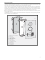
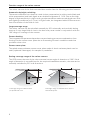
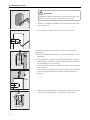
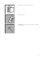
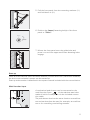
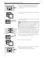
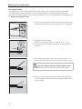
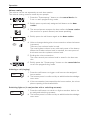
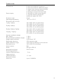
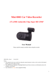
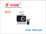
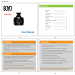
Installation and
Operating Instructions
Door Station Stainless
2551 20, 2552 20, 2553
2554 20, 2556 20, 2558
2559 20, 2560 20, 2562
Steel Video
20
20
20
Table of contents
Device description ......................................................................................................5
Function range of the colour camera...........................................................................6
Coverage range of the colour camera .........................................................................6
Selection of the installation site ..................................................................................7
Installing panel box .....................................................................................................8
Installing front panel ................................................................................................. 10
Start-up .................................................................................................................... 11
Multi-function input .................................................................................................. 11
Setting coverage range of the colour camera ............................................................ 12
Opening Door Station Stainless Steel ........................................................................ 13
Replacing inscription label ........................................................................................ 14
Operation .................................................................................................................. 16
Technical data.......................................................................................................... 17
Warranty .................................................................................................................. 18
3
4
Device description
The Door Station Stainless Steel Video is a pre-assembled, vandalism-protected door station with colour camera for the Gira door communication system.
The front plate of high-quality V2A stainless steel with a thickness of 3 mm is especially
robust. The call buttons are also made of durable stainless steel. The illuminated inscription labels are covered by a fully secured and flameproof glass plate. The inscription labels
can be opened via a covered mechanism and can then removed from the front.
Both the call buttons and inscription labels are uniformly illuminated with a white, powersaving LED element.
Loudspeaker and microphone are located behind the respective sound openings and are
water-resistant and vandal-proof.
2
3
1
6
4
4
5
7
8
9
1
2
3
4
5
6
7
8
9
10
11
Wall anchors (included)
Panel box
Locking plate
Plastic bracket
Catch strap hook
Front panel
Colour camera
Loudspeaker cover
Microphone
Name plates
Call buttons
10
4
11
5
Function range of the colour camera
The colour camera of the flush-mounted door station has the following product features:
Automatic day/night switching
The camera switches from daytime mode (colour presentation) to night mode (black and
white presentation) and back again at an ambient brightness of 1 Lux. Due to the high
degree of light sensitivity in night mode, good presentation results are achieved even with
poor lighting conditions (to 0.1 Lux). In night mode, the integrated white LEDs ensure an
even illumination of the field of view.
Large coverage range
The colour camera can be swivelled manually by 20º horizontally and vertically during
start-up. A very large field of view in the door entry area results in conjunction with the
100° range of coverage of the camera.
Camera heating
The integrated temperature-dependent camera heating prevents condensation from
forming on the camera cover plate due to fluctuating climactic conditions and thus
provides a clear view.
Camera cover plate
The splash water-resistant camera cover plate made of shock-resistant plastic can be
easily replaced if damaged, for example by vandalism.
Setting coverage range of the colour camera
The CCD sensor element of the colour camera has an angle of detection of 100°. If this
angle of detection is not sufficient for the required installation scenario, the area can be
manually swivelled by 20° in all directions.
Haustür
Türstation
Türstation
Haustür
0,6 m
0,6 m
20°
0,7 m
Coverage range of camera with
perpendicular lens.
6
1,4 m
Coverage range of camera when lens is
swivelled by 20°.
Selecting the installation site
The selection of the installation site and good illumination are critical for good picture
quality.
No backlighting
Do not point the colour camera towards strong backlighting, such as streetlamps or yard
illumination.
Prevent strong sunlight from hitting the lens.
Picture background
Avoid pointing the camera towards extremely bright image backgrounds and backgrounds with strong contrasts.
Lighting
LEDs integrated in the camera provide an even illumination of the field of view in darkness.
i
Black and white mode in poor lighting conditions
In poor lighting conditions (< 1 lux) or with the field of view illumination switched on, the
colour camera provides black and white pictures only.
If the entry area is equipped with additional illumination, this light source must not shine
directly into the camera lens from the front. The best installation site of an external light
source is above the colour camera.
Installation height
The recommended installation height of the colour camera is 1.50 m.
At this installation height, people with an average height of 1.80 m are optimally presented.
The minimum installation height is 1.20 m.
7
Installing panel box
Attention
Installation and mounting of electrical devices may
only be carried out by a qualified electrician.
1. Select a suitable installation site and chisel an opening in the wall.
2. If necessary, mount the included wall anchor.
Note the following information when mounting the
panel box:
• Ensure installation position is correct. (Note the "TOP"
labelling).
• The panel box must be installed level. With the later
mounting of the Door Station Stainless Steel there is
no possibility for correction.
• The panel box must be installed as flush to the surface
as possible!
It must be ensured that the locking plate can be flushmounted later. Maximum plaster compensation is
20 mm.
max.
20 mm
3. Plaster in the panel box to be flush with the final surface (maximum plaster compensation 20 mm).
8
4. Mount the included plaster protection.
5. Plaster the wall.
6. Carefully remove the plaster and take out the plaster protection.
9
Installing front panel
1. Insert the locking plate flushly into the panel box.
i
Insert locking plate evenly
The locking plate must not be twisted while being
installed into the panel box and must not be under
tension.
Push the locking plate inwards until the plastic
brackets touch the wall.
2. Fasten the locking plate with the 4 Allen bolts and
locking washers included.
In order to guarantee a secure fastening of the front
panel later, the Allen bolts must be firmly tightened.
3. Fold out both lateral mounting retainers (1.), slide
the front panel of the Door Station Stainless Steel
into the mounting retainers (2.) and attach the catch
strap of the front panel to the hook of the locking
plate (3.).
3.
1.
2.
ZV BUS
4. Connect the 2-wire bus to the BUS terminals.
10
i
Jumpers between BUS and ZV
The wire jumpers between BUS and ZV are required
for operation of the colour camera. Thus the illumination of the call buttons at the door station cannot be
switched off. If an external power supply is connected to the ZV terminals, the jumpers must be
removed.
5. Pull the front panel from the mounting retainers (1.)
and fold these in (2.).
2.
1.
6. Position the (lower) fastening bolt(s) of the front
panel to "Close".
Open
Close
7. Mount the front panel onto the guide bolts and
press it on until the upper and lower fastening bolts
engage.
Start-up
Once all of the devices (door and home stations, control device etc.) have been installed,
the door communication system can be started up.
Start-up a door station is described in the system manual included with the control device.
Multi-function input
A mechanical push button can be connected to the
multi-function input
of the stainless steel door
station's built-in loudspeaker via the included connection cable.
The push button then has the same function as a call button and can therefore be used, for example, as a call button or for controlling a switching actuator.
11
Setting range of coverage of colour camera
1. Remove the colour camera from the back of the
front panel of the Door Station Stainless Steel:
Loosen both screws of the attachment profile for
this purpose.
2. Remove the camera cover plate from the demounted
colour camera.
3. Slightly loosen both Torx screws to the left and right
of the camera lens.
i
Do not take out the screws completely!
When adjusting the lens carrier, it is sufficient to
slightly loosen the screws. Do not take out the
screws completely from their brackets.
4. Set the camera lens in the desired direction.
5. For testing purposes, install the colour camera in the
front panel and check on the TFT display of the connected home station whether the set angle of the
camera lens is adjusted properly, and whether the
view of the person in front of the door is optimal.
6. Remove the colour camera again and lock the lens
carrier by tightening both Torx screws.
7. Mount the camera cover plate.
8. Mount the camera into the front panel of the Door
Station Stainless Steel and fasten it.
Ensure proper seating of the black seal.
12
Opening of Door Station Stainless Steel
The included opening tool is required for opening the
Door Station Stainless Steel.
1. Turn the (lower) fastening bolt(s) with the opening
tool to "Open".
Single-column door stations have one lower fastening bolt, double-column door stations have two
lower fastening bolts.
The position of the fastening bolts is shown via small
recesses on the lower side of the front panel.
90°
Open
Take care with plastered walls
With repeated opening of the door station with
plastered walls, the opening tool may damage the
plaster.
90°
90°
Open
Open
2. Lift the front panel from the lower attachment (1.)
and pull it at an angle downwards from the upper
attachment retainers (2.).
2.
1.
13
Replacing inscription label
Inscription labels
For labelling the Gira Door Station Stainless Steel, use only Gira inscription labels.
The transparent plastic labels are non-fading, weather-resistant and wrinkle-free.
With the included release code, inscription labels for the first labelling are available free
at www.marking.gira.com
cli
ck
1. Unlock the call button with the enclosed plastic key:
twist the plastic key anti-clockwise until it engages.
120°
2. Engage the call button:
press the call button firmly inwards by c. 1 cm.
cli
1 cm
ck
✓ The call button engages and stays in the pressed
position.
3. Grip under the glass cover with the flat side of the
plastic key and twist out the inscription label carrier.
Do not remove the inscription label carrier.
Do not lift and remove the inscription label carrier.
4. Remove the existing inscription label and slide the
new inscription label into the inscription label carrier
until it stops.
Mu
a
rm
ste
14
nn
5. Position the inscription label underneath the clips of
the inscription label carrier.
6. Slide in the inscription label carrier again.
At the same time, position the inscription label with
your finger.
click
ustermann
click
7. Release the call button:
To do this, press in the plastic key slightly and turn it
clockwise until the call button is released from the
lower position.
8. Lock the call button:
To do this, turn the plastic key clockwise again until
it engages.
ustermann
9. For function test, press the call button:
the call button is correctly locked when
• the call button cannot be pressed in deeply and
• an acknowledgement signal is heard when the call
button is pressed.
If the call button is not correctly locked, please repeat
step 8.
15
Operation
Volume setting
The volume can be set separately at each door station.
The volume setting must be made by two people.
1. Press the "Systemprogr." button on the control device for
3 sec. to start programming mode.
1x
M. Meier
2. Briefly press a previously assigned call button at the door
station.
3. The second person accepts the door call at the home station
(via receiver or speech button) and starts speaking.
1x
4. Briefly press the call button again at the door station.
M. Meier
✓ Volume changes during the voice connection when the button
is pressed.
There are four volume levels in total.
The next-highest volume is set with each press of the button.
When the loudest volume level is reached, the next press of
the button sets the quietest volume level.
5. Ending the voice connection.
The most recently set volume level is saved in the door station.
6. Briefly press the "Systemprogr." button on the control device
to exit the programming mode.
Initiating a call (ringing)
M. Meier
1. Press the call button to trigger a call tone at the assigned
home station.
✓ The button press is confirmed by an additional acknowledgement tone.
✓ If the conversation is accepted by the home station, the microphone opening is illuminated blue.
Switching light on (in conjunction with a switching actuator)
Licht
1. Press the call button to switch on light or another device via
an assigned switching actuator.
✓ The button press is confirmed by an additional acknowledgement tone.
16
Technical data
Connections:
2
2
2
1
2
screw terminals for 2-wire bus
screw terminals for additional supply
system bus connector strips (6-pole)
video connector strip (2-pole)
sabotage contact screw terminals
Power supply:
2 cameras via video control device
3. and 4th camera via external
additional supply (24 V DC)
Protection type:
IP 44
Operating temperature:
-25 °C to +70 °C
Dimensions (W x H x D):
1-gang, 2-gang:
140 x 265 x 60 mm (panel box)
160 x 285 x 3 mm (front panel)
3-gang, 4-gang:
140 x 332 x 60 mm (panel box)
160 x 352 x 3 mm (front panel)
6-gang, 8-gang, 9-gang:
140 x 417 x 60 mm (panel box)
160 x 437 x 3 mm (front panel)
10-gang, 12-gang:
250 x 265 x 60 mm (panel box)
270 x 285 x 3 mm (front panel)
Camera installation height
Min. height:
Recommended installation height:
1.20 m
1.50 m
Image capture element:
CCD sensor 1/3"
Wide-angle objective:
150º aperture angle
Visible detection range:
100° angle of detection of the camera
Detectable area:
140° (with 20° swivelling)
Colour system:
PAL
Pixels:
500 (H) x 582 (V)
Horizontal resolution:
380 TV lines
Switching threshold
colour to B/W operation:
1 Lux
Light sensitivity
in B/W operation:
0.1 Lux
Electronic shutter
close time:
up to 1/100000 s
17
Warranty
The warranty is provided in accordance with statutory requirements via the specialist
trade.
Please submit or send faulty devices postage paid together with an error description to
your responsible salesperson (specialist trade/installation company/electrical specialist
trade).
They will forward the devices to the Gira Service Center.
18
19
Postfach 1220
42461 Radevormwald
Deutschland
Tel +49 (0) 21 95 / 602 - 0
Fax +49 (0) 21 95 / 602 - 191
www.gira.de
[email protected]
10 41 09 25 20/11
Gira
Giersiepen GmbH & Co. KG
Elektro-InstallationsSysteme