1
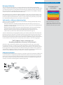
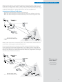
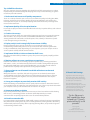
NETWORK INSTRUMENTS WHITE PAPER
Your Guide to Troubleshooting VoIP
VoIP’s extreme sensitivity to delay and packet loss compared
to other network applications such as web and e-mail services,
presents a real challenge. A basic understanding of VoIP traffic
and of the quality metrics provided by VoIP monitoring tools
will help keep your network running smoothly.
www.networkinstruments.com
NETWORK INSTRUMENTS WHITE PAPER
Your Guide to VoIP
This white paper guides you through the essentials of VoIP troubleshooting, including
common problems and the metrics you should employ to fix and prevent them. You’ll learn
how these metrics relate to one another and to overall VoIP health. You’ll also learn the best
practices for keeping your VoIP network flowing smoothly, your time-to-resolution low, and
end users happy.
Network Jitter and Delay
Real-time voice communications are sensitive to delay and variation in packet arrival times.
Codecs require a steady, dependable stream of packets to provide reasonable playback
quality. Packets arriving too early, too late, or out of sequence result in jerky, jumbled
playback. This phenomenon is called jitter.
Increasing jitter buffer size
can help, but only to a point.
Because no network can guarantee a perfectly steady stream of packets under real-world
conditions, VoIP phones use jitter buffers to smooth out the kinks. A jitter buffer is simply a
First-In, First Out (FIFO) memory cache that collects the packets as they arrive, forwarding
them to the codec evenly spaced and in proper sequence for accurate playback.
A major Midwest health
provider recently undertook a
major VoIP deployment.
The hospital used Observer® Expert
to conduct network assessments to
benchmark network performance
before implementing VoIP.
“We were in the middle
of a significant VoIP
deployment and had
plans for implementing
other critical network
applications.
We really needed
some type of network
analyzer to monitor
and maintain network
performance.”
Jack King,
Director of I.T.
While a jitter buffer can successfully mask mild delay and jitter problems, severe jitter can
overwhelm the jitter buffer, which results in packet loss (see below). Increasing the size of
the jitter buffer can help, but only to a point: A jitter buffer that increases overall round-trip
delay to 300 ms will make normal conversation difficult.
Packet Loss
As mentioned above, packet loss can be the result of the jitter buffer being overwhelmed.
Other reasons include landline media failure and poor wireless signal quality. The latter can
be a big problem with VoFi (Voice over WiFi) service. Regardless of the source, VoIP phones
and gateways attempt to conceal this type of signal degradation by duplicating packets to fill
in the missing data. As with jitter, these techniques can maintain voice quality only to a point.
Packet loss on data networks has long been characterized as a “bursty” phenomenon,
which is another way of saying “it never rains, it pours.” Networks tend to either sporadically
drop single packets (these periods are called “gaps” in packet loss), or large numbers of
contiguous packets in a “burst.” Packet loss concealment techniques typically have no
problem handling packet loss during gap periods; it is the sustained bursts you must watch
out for.
Call Management Problems
If the VoIP call manager (sometimes called the VoIP server) is overwhelmed with requests,
or its connection to the network is impaired, call setup delays can reach the point where
users abandon calls before they are able to connect to the other party. If IP phones are
misconfigured, or their IP connection to the server is impaired, calls remain open in the
call queue long after the parties have disconnected.
2
NETWORK INSTRUMENTS WHITE PAPER
Managing VoIP Quality
You can manage only what you can measure. Managing a VoIP deployment therefore
requires some hard numbers beyond subjective user assessments of quality (although these
are obviously important as well). Beyond monitoring the network parameters discussed in
this paper, having an overall quality score such as a Mean Opinion Score (MOS) or R-factor
score can also be a useful VoIP network health index.
R
100
90
80
VoIP monitoring tools calculate the MOS and R-factor scores using a formula known as the
E-model. Using the statistics it has collected from the network, the analyzer calculates how
much the various impairment factors (such as codec compression, jitter, delay, and packet
loss) would affect the typical user’s perception of call quality.
70
60
50
0
VoIP-Specific vs. All-Purpose Monitoring Tools
There are a number of different options on the market for managing VoIP quality, mainly
falling into three categories:
• Dedicated VoIP tools originally developed for the telecom industry. These tools are
great for testing IP phone and gateway designs, but not as good at solving deployment
problems on a live network.
• Network protocol analyzers that have added “VoIP Support” by licensing technology
developed for the telecom industry and integrating it into their product line.
• Network monitoring tools that approach VoIP quality management from an IT
administrator’s point of view rather than from that of telecom engineer.
How Call Quality Relates to
User Satisfaction
Very Satisfied
Satisfied
Some Users Dissatisfied
Many Users Dissatisfied
Nearly All Users Dissatisfied
Not Recommended
MOS
4.3
4.0
3.6
3.1
2.6
1.0
MOS and R-factor are used to
gauge user satisfaction with call
quality. MOS levels under 3.5 and
R-factor below 80 mean trouble.
To the IT administrator, managing VoIP quality is just another network task. This makes the
third approach (the “all-purpose” network monitoring tool) often the most practical choice.
But note that “VoIP support” means more than just decoding the packets of various VoIP
protocols; it also means being able to track and display network delay, jitter, and packet loss,
and to distill this information into overall quality scores, both per-call and in aggregate.
“VoIP Support” means more than just
decoding the packets of various VoIP protocols.
And to be really useful to the enterprise, the tool should also track, store, and analyze
long-term trends. This is so that you can understand what is “normal” VoIP performance,
and maintain a database of Call Detail Records (CDRs) from which you can generate reports
for management or service providers. The VoIP monitoring tool should also be capable of
automatically notifying you when selected statistics indicate a developing problem. On all
of these counts, Network Instruments® Observer® meets the requirements.
VoIP Points of Visibility
In switched environments, where to deploy an analyzer or probe for maximum visibility isn’t
necessarily obvious. Complicating matters for VoIP is the fact that each call includes both
client-server communications (between IP phones and the call manager during setup and
tear-down), and peer-to-peer (the streams of voice data passed between the parties). For
example, consider the following VoIP network deployment:
VoIP Call
Manager
Access Layer
West Coast
Office
Core Switch
MPLS
Mesh
VoIP Call
Manager
Core Switch
Access Layer
East Coast
Office
3
NETWORK INSTRUMENTS WHITE PAPER
Where to place probes on such a network depends on what you want or need to see. If you
need access to all local conversations on either coast, including both call setup and actual
voice data, use a SPAN session on the access layer switch to mirror VoIP traffic to the analyzer.
Assigning all VoIP traffic to a dedicated VLAN makes this fairly straightforward.
Capturing Local IP Phone Traffic Shows:
• Any phone’s communications with its local call manager
• Both sides of the full-duplex connection between local phones talking to each other
• Both sides of the full-duplex connection between phones located on opposite coasts
West Coast
Office
VoIP Call
Manager
SPAN
All IP
Access Switch
Pho
n
VoIP Call
Manager
e Po
rts
Analyzer/
Probe
Connection visible to analyzer
Connection hidden from analyzer
East Coast
Office
What you will not be able to see from this probe is any communications between the East
Coast and the call manager located on the West Coast.
If you are more interested in a coherent view of calls between the West Coast and East
Coast, including all call manager communications, use a SPAN session to mirror both the
uplink traffic between the core and MPLS mesh, and all traffic flowing to and from the call
manager. This will give you a coherent view of inter-office calls, along with all call manager
communications, both local and remote.
West Coast
Office
VoIP Call
Manager
“Observer wins
hands down.”
Access Switch
k&
Uplin rts
SPAN nager po
Ma
Call
Core
Switch
Upl
ink
VoIP Call
Manager
Christian Wilson,
Network Administrator
Select Comfort
Analyzer/
Probe
Connection visible to analyzer
Connection hidden from analyzer
East Coast
Office
4
NETWORK INSTRUMENTS WHITE PAPER
With a probe deployed in this manner, you will not be able to see the peer-to-peer voice
traffic between local phones. For complete coverage, connect probes to both the core and
access layers at each site. Another alternative is to deploy probes at the core 24/7/365,
monitoring the access layer with a portable analyzer or software probe only to troubleshoot
local call problems as needed.
VoIP Network Analysis
How can VoIP analysis help manage quality? By closely monitoring the network conditions
that affect VoIP, you can begin to address developing infrastructure problems before they
result in user complaints or downtime.
Tracking Network Performance
Consider the East Coast/West Coast example described in the previous section. Ken, the
administrator responsible for ensuring VoIP quality, has set up a Network Instruments
10/100/1000 Probe Appliance on the core switch to monitor all call manager activity and any
VoIP traffic traversing the link. He has configured Observer to send him an e-mail whenever
any of the following conditions arise:
• MOS falls to 3.5 or less
• Jitter levels crossing the MPLS mesh exceed 20 ms
• Delay levels crossing the MPLS mesh exceed 80 ms
Any of these conditions are indications that VoIP quality is threatened. Given the topology
involved, the most likely source of problems is the MPLS mesh routers, which are under the
service provider’s control. By digging deeper into the statistics the analyzer provides, you
can determine why the MOS is falling, and what is causing jitter, delay, or packet loss.
“With Observer it’s
like looking in 60
directions at once.”
Coleman Jennings,
Senior Network Engineer
AAA East Central
If jitter is the problem, a good place to start is by comparing jitter levels against bandwidth
utilization to see if there is any correlation. The analysis shown below (taken from Network
Instruments’ Observer Expert) shows just such a correlation.
Station 1 to Station 2
Station 2 to Station 1
Bandwidth Utilization
Comparing Jitter to Bandwidth Utilization
As this scenario shows, such a link between spikes in bandwidth and jitter could mean it is
time to invest in more bandwidth, or time to put more controls on employee Internet usage
for applications such as streaming media and peer-to-peer file sharing unrelated to business.
If there isn’t an obvious correlation between jitter and bandwidth utilization, the depth of
data provided by an all-purpose network analysis and monitoring tool can help you dig
deeper for the correct diagnosis. For example, if VoIP traffic across an MPLS mesh is subject
to excessive jitter, it could be the result of “route flapping” on the service provider’s routers.
An analyzer can confirm and document this. Armed with the hard data provided by analysis,
you could then contact the service provider so they can address the problem. If delay across
the mesh exceeds the contractual obligations of the Service Level Agreement (SLA), the
provider may owe your organization some refunds for service failure, in addition to being
responsible for fixing the problem.
5
NETWORK INSTRUMENTS WHITE PAPER
Troubleshooting Connection Problems
When a user can’t get a dial tone, or if there are excessive delays in ringing the other party’s
phone, examining a graphical display of how the call is progressing between the parties and
the call manager can indicate what is going wrong.
Network Instruments’ VoIP Expert displays just such a diagram: simply right-click on any
call or connection stream. Because differing protocols dictate differing phone/call manager
interactions, some knowledge of the protocol is necessary for detailed troubleshooting. But
even if you lack a detailed knowledge of the protocol, the Connection Dynamics display
highlights which party isn’t responding, or which party is responding slowly.
1
Picks up handset
2
Call manager turns
on dialtone and
displays message
on IP phone
ohone A
3
Dials number
“The Network
Instruments tools
let me reconstruct
an entire VoIP
conversation and
hear it real-time.”
“This tool set allows
me to have eyes into a
customer’s network.”
Ivan McDuffie,
NEC Unified Solutions
4
Ringing IP phone B
5
Acknowledgement
that phone B is ringing
6
Picks up handset
7
Conversation begins
An example of a Connection Dynamics display showing a VoIP call using the SCCP protocol. It is
easy to see how such a diagram is essential to efficiently troubleshoot VoIP connection problems.
Better manage and troubleshoot VoIP across your network using Observer’s VoIP Expert,
available in Observer Expert and Observer Suite. Whether you’re interested in the big picture
or a specific conversation, Observer offers real-time statistics, Expert VoIP analysis, and
reports to help you address all levels of VoIP traffic.
Over 70 VoIP-specific metrics.
Understanding VoIP performance is the key to accurate troubleshooting. Observer provides
visibility into the network, application, and VoIP traffic to quickly resolve issues. VoIP
Expert summaries provide easy understanding of overall VoIP network health. Over 70
VoIP-specific metrics like call quality can be tracked on an aggregate or per-call basis. Take
advantage of over 50 VoIP Expert events for immediate problem identification. Once you’ve
identified the issue, drill-down on specific conversations for an in-depth view.
VoIP Expert Analysis Features
Convenient, at-a-glance summaries
• VoIP Traffic Summary
• Call Summary
• Voice Quality Scoring
• Precedence (QoS)
6
NETWORK INSTRUMENTS WHITE PAPER
Detailed views with in-depth Call Detail Records
• Addresses
• Status (Open, closed, fail)
• Number of packets, packet bytes, packet loss
• Start time, initial setup duration, duration
• Current jitter, maximum jitter
• MOS, R-factor
• QoS for each call
• Number of packets that arrive out of order
• Detailed analysis for packet loss and delay
• Gap and burst measurements
• Long-term Call Detail Records trending
Observer’s VoIP Expert
Quickly Solve Problems with over 50 VoIP Experts
Observer offers over 50 event-based and threshold-based VoIP Experts to immediately flag
problems for faster problem resolution. Examples include:
• Alarms for unacceptable jitter level
• Lost packets
• Alterations in the QoS stream
Manage VoIP Audio Quality
Observer displays individual Mean Opinion Score (MOS) and R-factor for individual calls and
as an average. Place alarms on this score to proactively manage overall VoIP quality.
Plotting jitter in milliseconds.
Monitor Quality of Service (QoS)
Observer’s VoIP Expert reports QoS levels by call, packet, and protocol. This analysis also
shows percentage of VoIP utilization compared to other network traffic, allowing you to plan
network upgrades.
Evaluate Jitter
Observer’s VoIP Expert displays the statistical variance of packet arrival times, known as jitter,
measured in timestamp units or RTP time units.
Measure Bursts and Gaps
Observer’s VoIP Expert provides comprehensive metrics for monitoring bursts, or periods of
high packet loss, and gaps, or periods of little packet loss. Burst and gap percentages quickly
indicate the quality of a call.
Track and Decode VoIP and Video
Observer offers complete VoIP and video decodes, including H.323, Session Initiation
Protocol (SIP), MGCP, and SCCP (Cisco “skinny”). Observer also supports Avaya CCMS, Nortel
UNIStim, and Mitel® systems.
Reconstruct and Review VoIP Calls
Capture and reconstruct calls for playback, so you can hear the same call quality issues
experienced by users.
Compare VoIP to Network Performance
Use Observer to identify whether jitter or delay is being caused by other applications on the
network. Observer will track VoIP issues along with overall network performance.
Monitor VoWLAN
Observer’s VoIP enhancements are automatically available across multiple topologies, thanks
to the Network Instruments Distributed Network Analysis (NI-DNA™) architecture. Observer’s
VoIP Expert will monitor VoIP traffic even over wireless networks.
7
NETWORK INSTRUMENTS WHITE PAPER
Top 10 VoIP Best Practices
Our sales engineers have put together this valuable list of the best practices to use when
implementing or troubleshooting VoIP. Keeping these steps in mind will help you get the
most from your VoIP network.
1. Understand and measure call quality components
There are a variety of metrics you can use to assess VoIP call quality, including jitter, MOS,
R-Factor, gap density, burst density, Quality of Service prioritization, and compression
techniques. Ensure you are accurately analyzing VoIP communication by learning how to
measure these attributes.
2. Implement Quality of Service prioritization
Incorrectly set QoS precedence for VoIP traffic leads to delays in packet delivery and reduced
call quality.
3. Conduct site surveys
The more you know about your network, the better prepared you are to properly integrate
VoIP. Conduct a site survey to review current WAN bandwidth levels, traffic flows, and
existing switches for bottlenecks and choke points. Then, identify or determine specific
needs through testing and modeling.
4. Deploy analysis tools strategically for maximum visibility
Placing network analysis consoles and probes on your network requires a clear
understanding of VoIP traffic patterns. Are you concerned with monitoring VoIP traffic
locally, over WAN links, both? Depending on your objectives, place your analysis tools to
ensure optimal visibility of VoIP communications.
5. Implement VLANs to isolate and monitor VoIP issues
Organize your VoIP traffic by VLAN user groups. This practice will greatly simplify problem
resolution.
6. Monitor rollouts to ensure a positive user experience
Determine whether users are receiving a positive experience by reviewing cumulative
VoIP metrics, codecs, and other network performance variables during VoIP deployment.
By evaluating VLAN setups and overall link utilization, you can judge overall network
performance and quickly make adjustments during implementation.
7. Compare jitter to overall network bandwidth utilization to understand
response time
When jitter becomes a problem, look at the big picture. A correlation between jitter
and bandwidth usage means the problem is overall network usage. If there is no direct
correlation, excessive jitter might be caused by isolated network factors that require
further investigation.
8. Set up your analyzer to proactively monitor VoIP activity
Utilize monitoring and notification tools to speed problem resolution. Determine “normal”
or “acceptable” levels of activity for your network and its users. Then set up thresholds within
your analyzer to alert you when thresholds are broken or in danger.
9. Automate problem resolution
Expert Analysis functionality eliminates unnecessary trial and error when troubleshooting
VoIP issues by automating problem resolution. Utilize Expert Analysis on VoIP
communication to quickly pinpoint the source of common VoIP problems.
10. Baseline network traffic
For comprehensive understanding of VoIP traffic, capture and store long-term network data.
Only with critical trending data can you accurately perform baselining activities. Baselining
validates VoIP performance, helps future capacity planning efforts, and provides long-term
understanding of VoIP health.
CI Travel’s VoIP Savings
High phone bills were eating up
CI Travel’s profits. They decided to
take advantage of VoIP technology
to reduce per-call expenses.
The new VoIP phones, while
dramatically reducing per-call costs,
came with new problems. To make
the investment pay off, Ingram
required tools to monitor and
troubleshoot the VoIP exchange.
“So far, Observer’s
VoIP capabilities have
helped cut CI Travel’s
phone bill by 25 to 30
percent.”
Paul Ingram,
Director of IT
– CI Travel is a $150 million
division of Cruise International.
8
NETWORK INSTRUMENTS WHITE PAPER
Summary of VoIP statistics and quality metrics
The following table summarizes the statistics and quality measurements discussed in this
paper, both defining what is measured, and describing its relevance.
VoIP metric
What it measures
How to use the analysis
Jitter
Jitter measures the variability of delay in packet
arrival times. In spite of the jitter buffers used
to counteract jitter, at excessive levels it can
interfere with smooth playback and cause
packets to be dropped.
By using triggers to notify you when jitter levels
are reaching a point that threaten voice quality,
you can examine your routers for problems or
contact your service provider and help them
solve the problem.
Delay
The amount of time it takes a packet to reach its
destination. Whenever packets travel a network,
some delay is inevitable. For real-time telephone
conversations, there is a one-way “delay budget”
of approximately 150 ms.
As with jitter, using automatic notifications to
actively manage levels of delay can prevent the
problem from escalating to the point where users
complain.
Packet loss
The percentage of packets that did not reach
their destination.
Sporadic packet loss is usually insignificant.
However, sustained bursts (see the next item) can
affect quality.
Bursts
Periods characterized by high rates of packet loss.
The burst percentage is the percentage of time
that the call experienced high-rate packet loss;
the burst density is the actual percentage rate of
packet loss during bursts.
VoIP phones have no trouble masking a lost
packet here and there by duplicating the
previous packet or filling longer silences with
white noise. But users will notice sustained bursts.
If VoIP traffic has been assigned proper QoS and
has enough bandwidth, the most likely culprit is
media failure.
Gaps
Periods characterized by low rates of packet loss.
The gap percentage is the percentage of time
that the call experienced low-rate packet loss;
the gap density is the actual percentage rate of
packet loss during the gaps.
Usually not significant, as packet loss
concealment technologies are usually successful
in masking the effects of low-level packet loss.
Contrast with bursts, described above.
Average call setup/teardown
An average of how long it is taking the call
manager to open and close calls.
A spike in these statistics can indicate a problem
with the call manager or its connectivity to the
network.
Codec
The compression/decompression method that
was used for the call.
Different codecs are capable of different levels of
quality sound reproduction. Higher compression
comes at the cost of lower quality, but may be
necessary given the bandwidth available to the
call. If it seems as if the codecs in use are using
more compression than necessary (or not enough)
given the amount of bandwidth available, perhaps
the VoIP phones can be reconfigured to use a
different codec.
Mean Opinion Score (MOS)
Starting with a theoretical perfect score of 5
(excellent), impairment factors such as codec,
delay, jitter, and packet loss are used to calculate
how a typical user would rate
voice quality.
R-factor
Similar to MOS, this scale ranges from 1-100.
These are useful as quick overall indicators of VoIP
health. If the average MOS falls below 3.5, or the
average R-factor falls below 80, it’s likely that you
have more than a few dissatisfied users. If you
see these statistics trending downward, it’s time
to examine more detailed analysis to determine
what is going wrong.
Corporate Headquarters
Network Instruments, LLC • 10701 Red Circle Drive • Minnetonka, MN 55343 • USA
toll free (800) 526-7919 • telephone (952) 358-3800 • fax (952) 358-3801
www.networkinstruments.com
© 2007 Network Instruments, LLC. All rights reserved. Network Instruments, Observer, GigaStor, NI-DNA, and all associated logos are trademarks or registered trademarks of Network Instruments, LLC.
All other trademarks, registered or unregistered, are sole property of their respective owners. October 2007
9