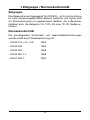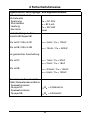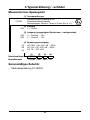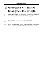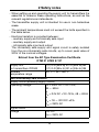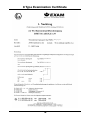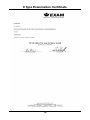
1
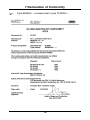
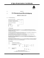
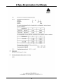
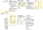
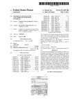
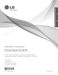
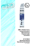
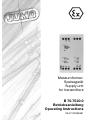
MessumformerSpeisegerät
Supply unit
for transmitters
B 70.7520.0
Betriebsanleitung
Operating Instructions
03.07/00359391
Besonderheiten
II (1) G D [EEx ia] IIC oder [EEx ia] IIB
II (2) G D [EEx ib] IIC oder [EEx ib] IIB
A
Die Konformitätserklärung (Seite 14) und die Baumusterprüfbescheinigung (Seite 15) sind zu beachten.
H
Der Typ 956056/... entspricht dem Typ 707520/....
H
Innerhalb der EU-Mitgliedsstaaten kann diese Betriebsanleitung auf Wunsch in einer anderen EU-Landessprache angefordert werden.
1 Zielgruppe / Normenkonformität
Zielgruppe
Das Messumformer-Speisegerät Typ 707520/... ist für die Errichtung
im nicht explosionsgefährdeten Bereich bestimmt und eignet sich
zur Stromversorgung von eigensicheren Geräten, die in Bereichen
installiert sind, die Kategorie 1G, 1/2G, 2G oder 1D, 2D Geräte erfordern.
Normenkonformität
Die grundlegenden Sicherheits- und Gesundheitsanforderungen
werden erfüllt durch Übereinstimmung mit:
- EN 50 014 + A1 + A2:
1997
- EN 50 020:
1994
- EN 50 284:
1999
- EN 50 281-1-1:
1998
- EN 61 326-1:
1997
3
2 Sicherheitshinweise
- Die Errichtung und der Betrieb des Messumformer-Speisegerätes
muss mit Hilfe dieser Betriebsanleitung und den für sie gültigen
Regeln und Normen erfolgen.
- Das Messumformer-Speisegerätes ist für die Errichtung im nicht
explosionsgefährdeten Bereich bestimmt.
- Die Umgebungstemperaturen dürfen die in der nachstehend aufgeführten Tabelle angegebenen Grenzwerte nicht überschreiten.
- Galvanische Trennung besteht zwischen:
- Hilfsenergie und eigensicherem Eingang
- Hilfsenergie und Ausgang
- eigensicherem Eingang und Ausgang
Der eigensichere Versorgungs- und Signalstromkreis ist von den
nicht eigensicheren Stromkreisen bis zu einer Summe der Scheitelwerte der Nennspannungen von 375V sicher galvanisch getrennt.
Auszug aus der EG-Baumusterprüfbescheinigung
DTM 01 ATEX E 137
MessumformerII (1) G D [EEx ia] IIC oder [EEx ia] IIB
Speisegerät 707520
II (1) G D [EEx ib] IIC oder [EEx ib] IIB
Umgebungs-20°C ≤ Ta ≤ +65°C
temperaturbereich
Nicht eigensichere Stromkreise
Versorgungsstromkreis (Hilfsenergie)
Betriebsspannung
Un = AC 230V +10/-15%, 48…63Hz
bzw.
Un = AC 24V +10/-15%, 48…63Hz
bzw.
Un = DC 18 … 32V ±0%
Um = AC 250V
Signalstromkreis
Spannung
DC 15V
Um = AC 250V
4
2 Sicherheitshinweise
Eigensicherer Versorgungs- und Signalstromkreis
sicherheitstechnische
Höchstwerte
Uo = DC 25V
- Spannung
- Stromstärke
Io = 87,4mA
- Leistung
Po = 547mW
- Kennlinie
linear
höchstzulässige äußere
Induktivität/Kapazität
EEx ia IIC / EEx ib IIC
Lo = 4mH / Co = 105nF
EEx ia IIB / EEx ib IIB
Lo = 15mH / Co = 620nF
bei gemischter Anschaltung:
EEx ia IIC
Lo = 1mH / Co = 30nF
Lo = 2mH / Co = 18nF
EEx ia IIB
Lo = 3,3mH / Co = 152nF
Lo = 5mH / Co = 130nF
Maximales äußeres Induktivitäts-Widerstandsverhältnis
- Speisestromkreis
Gruppe IIC
Lo/Ro = 0,065mH/Ω
- Speisestromkreis
Gruppe IIB
Lo/Ro = 0,26mH/Ω
5
3 Typenerklärung / -schilder
Messumformer-Speisegerät
(1) Grundausführung
x
Messumformer-Speisegerät für
Zweidraht-Messumformer
Abmessungen: 45mm x 76mm x 91mm (B x H x T)
(2) Eingang
091
4 … 20mA
x
x
(3) Ausgang (eingeprägter Gleichstrom - konfigurierbar)
030
0 ... 20mA/0 ... 10V
032
4 ... 20mA/2 ... 10V
707520
x
x
x
(4) Spannungsversorgung
02
AC 230V +10/-15%, 48 ... 63Hz
08
AC 24V +10/-15%, 48 ... 63Hz
DC 18 ... 32V ±0%
24
Bestellschlüssel
Bestellbeispiel
(1)
(2)
(3)
(4)
707520 / 091 707520 / 091 - 030 - 02
Serienmäßiges Zubehör
- 1 Betriebsanleitung 70.7520.0
6
3 Typenerklärung / -schilder
Die nachfolgende abgebildeten Typenschilder befinden sich auf
dem Gehäuse des Messumformers.
Der F-Nr. (Fabrikations-Nummer) kann das Produktionsdatum (Jahr/
Woche) entnommen werden. Es handelt sich hierbei um die Zeichen
12, 13, 14, 15.
Beispiel:
F-Nr. 0041367101001490014
Das Messumformer-Speisegerät wurde demnach in der 49. Woche
2001 produziert.
7
4 Technische Daten
- Kennzeichnung:
II (1) G D [EEx ia] IIC oder [EEx ia] IIB
II (2) G D [EEx ib] IIC oder [EEx ib] IIB
- EG-Baumusterprüfbescheinigung: DMT 01 ATEX E 137
siehe Kapitel 2 „Sicherheitshinweise“ und
Kapitel 8 „Baumusterprüfbescheinigung“
- Konformitätserklärung: siehe Kapitel 7 „Konformitätserklärung“
- Typenblatt: T 70.7520
8
5 Installation
Für das Errichten/Betreiben sind die Vorschriften gemäß ElexV und
diese Betriebsanleitung maßgebend. Die maximale Umgebungstemperatur (siehe Kapitel 2 „Sicherheitshinweise“) ist unbedingt einzuhalten.
Abmessungen
Tragschiene:
Hutschiene 35mm x 7,5mm EN 60 715
Tragschiene:
G-Schiene EN 60 715
9
Tragschiene:
Hutschiene 15mm EN 60 715
5 Installation
Anschlussplan
Anschluss für
Anschlussbelegung
Spannungsversorgung L1
Außenleiter
lt. Typenschild
AC
N
Neutralleiter
L+
DC
L10
5 Installation
Anschluss für
Analoge Eingänge
ZweidrahtMessumformer
4 … 20mA
Anschlussbelegung
+11
eigensicherer Stromkreis
-12
Leitungswiderstand
14V – U
R = -----------------------B20mA
UB = minimale Beriebsspannung des angeschlossenen ZweidrahtMessumformers
Analoge Ausgänge
Spannung
0(2) ... 10V
+31
RLast ≥ 250 kΩ
-32
33
Strom
0(4) ... 20mA
+31
Drahtbrücke zu
Klemme -32
RBürde ≤ 750 Ω
-32
Die Umschaltung zwischen Strom- und Spannungsausgang erfolgt
über eine Drahtbrücke an Anschluss -32 und 33.
11
5 Installation
Anschlussbeispiel
Messumformer-Speisegerät
Ex-Bereich
Nicht Ex-Bereich
Ex-ZweidrahtMessumformer
+
=
MessumformerSpeisegerät
+
+
4...20 mA
-
Regler
-
= =
~
L1
+
Anzeigegerät
-
+
Registriergerät
-
+
-
+
-
0...20 mA / 4...20 mA
-
N
+
-
+
+
0...10 V / 2...10 V
-
12
-
6 Instandhaltung
Die für die Wartung/Instandsetzung/Prüfung geltenden Bestimmungen sind einzuhalten. Im Rahmen der Wartung sind vor allem Teile
zu prüfen, von denen die Zündschutzart abhängt.
13
7 Konformitätserklärung
H
Der Typ 956056/... entspricht dem Typ 707520/....
14
8 Baumusterprüfbescheinigung
15
8 Baumusterprüfbescheinigung
16
8 Baumusterprüfbescheinigung
17
8 Baumusterprüfbescheinigung
18
8 Baumusterprüfbescheinigung
19
JUMO GmbH & Co. KG
Hausadresse:
Moltkestraße 13 - 31
36039 Fulda, Germany
Lieferadresse:
Mackenrodtstraße 14
36039 Fulda, Germany
Postadresse:
36035 Fulda, Germany
Telefon: +49 661 6003-0
Telefax: +49 661 6003-500
E-Mail: [email protected]
Internet: www.jumo.net
JUMO Mess- und Regelgeräte
Ges.m.b.H.
Pfarrgasse 48
1232 Wien, Austria
Telefon: +43 1 610610
Telefax: +43 1 6106140
E-Mail: [email protected]
Internet: www.jumo.at
JUMO Mess- und Regeltechnik AG
Laubisrütistrasse 70
8712 Stäfa, Switzerland
Telefon: +41 44 928 24 44
Telefax: +41 44 928 24 48
E-Mail: [email protected]
Internet: www.jumo.ch
Supply unit
for transmitters
B 70.7520.0
Operating Instructions
Special features
A
Please take note of the Declaration of Conformity (page 14)
and of the Type Examination Certificate (page 15).
H
Type 956056/... corresponds to type 707520/....
H
Within the European Union, these Operating Instructions
can be supplied in a different EU language, if requested.
1 Intended use / Conformity with standards
Intended use
The supply unit for transmitters type 707520/... is intended for operation in non-hazardous areas. It is suitable for supplying power to
intrinsically safe equipment that is installed in areas which require
category 1G, 1/2G, 2G or 1D, 2D equipment.
Conformity with standards
The fundamental safety and health requirements are fulfilled
through compliance with the following standards:
- EN 50 014 + A1 + A2:
1997
- EN 50 020:
1994
- EN 50 284:
1999
- EN 50 281-1-1:
1998
- EN 61 326-1:
1997
3
2 Safety notes
- When setting up and operating the supply unit for transmitters it is
essential to observe these operating instructions, as well as the
relevant regulations and standards.
- The transmitter supply unit is intended for use in non-hazardous
areas.
- The ambient temperatures must not exceed the limits specified in
the table below.
- Electrical isolation is provided between:
- auxiliary supply and intrinsically safe input
- auxiliary supply and output
- intrinsically safe input and output
The intrinsically safe supply and signal circuit is safely isolated
from the non-intrinsically safe circuits, up to a sum peak value of
375V of the nominal voltages.
Extract from the EC Type Examination Certificate
DTM 01 ATEX E 137
Supply unit
II (1) G D [EEx ia] IIC or [EEx ia] IIB
for transmitters 707520
II (1) G D [EEx ib] IIC or [EEx ib] IIB
Ambient
-20°C ≤ Ta ≤ +65°C
temperature range
Non-intrinsically safe circuits
Supply circuit (auxiliary supply circuit)
Operating voltage
Un = 230V AC +10/-15%,
48 — 63Hz
or
Un = 24V AC +10/-15%, 48 — 63Hz
or
Un = 18 — 32V DC ±0%
Um = 250V AC
Signal circuit
Voltage
15V DC
Um = 250V AC
4
2 Safety notes
Intrinsically safe supply and signal circuit
Maximum safe values
- voltage
Uo = 25V DC
- current
Io = 87.4mA
- power
Po = 547mW
- characteristic
linear
Max. permissible external
inductance/capacitance
EEx ia IIC / EEx ib IIC
Lo = 4mH / Co = 105nF
EEx ia IIB / EEx ib IIB
Lo = 15mH / Co = 620nF
for combined installation:
EEx ia IIC
Lo = 1mH / Co = 30nF
Lo = 2mH / Co = 18nF
EEx ia IIB
Lo = 3.3mH / Co = 152nF
Lo = 5mH / Co = 130nF
Maximum external
inductance-resistance ratio
- supply circuit
Group IIC
- supply circuit
Group IIB
Lo/Ro = 0.065mH/Ω
Lo/Ro = 0.26mH/Ω
5
3 Type designation / labels
Supply unit for transmitters
(1) Basic version
x
Transmitter supply unit for
2-wire transmitters
dimensions: 45mm x 76mm x 91mm (W x H x D)
(2) Input
091
4 — 20mA
x
x
(3) Output (proportional DC current - configurable)
030
0 — 20mA/0 — 10V
032
4 — 20mA/2 — 10V
707520
x
x
x
(4) Supply
02
230V AC +10/-15%, 48 — 63Hz
08
24V AC +10/-15%, 48 — 63Hz
18 — 32V DC ±0%
24
Order code
Order example
(1)
(2)
(3)
(4)
707520 / 091 707520 / 091 - 030 - 02
Standard accessories
- 1 Operating Instructions 70.7520.0
6
3 Type designation / labels
The labels shown below are attached to the transmitter housing.
* details on type code, sales number, auxiliary supply and
serial number as per order
The serial number (F-Nr.) indicates the production date (year/week).
The figures concerned are in position 12, 13, 14, 15.
Example:
F-Nr. 0041367101001490014
The transmitter supply unit was manufactured in 2001, week 49.
7
4 Technical data
- Marking:
- EC Type Examination Certificate: DMT 01 ATEX E 137
see Chapter 2 “Safety notes” and
Chapter 8 “Type Examination Certificate”
- Declaration of Conformity:
see Chapter 7 “Declaration of Conformity”
- Data Sheet: T 70.7520
8
5 Installation
The regulations according to ElexV and these Operating Instructions apply when setting up and operating the equipment. It is absolutely essential to observe the maximum ambient temperature
(see Chapter 2 “Safety notes”).
Dimensions
Mounting rail:
C-rail 35mm x 7.5mm EN 60 715
Mounting rail:
G-rail EN 60 715
9
Mounting rail:
C-rail 15mm EN 60 715
5 Installation
Connection diagram
Connection for
Supply
see nameplate
Terminals
L1
line
AC
N
neutral
L+
DC
L10
5 Installation
Connection for
Analog inputs
2-wire
transmitter
4 — 20mA
Terminals
+11
intrinsically safe circuit
-12
lead resistance
14V – U
R = -----------------------B20mA
UB = min. operating
voltage of the 2-wire
transmitter connected
Analog outputs
Voltage
0(2) — 10V
+31
Rload ≥ 250 kΩ
-32
33
Current
0(4) — 20mA
+31
wire link to
terminal -32
Rburden ≤ 750 Ω
-32
The changeover between current and voltage output takes place via
a wire link at terminal -32 und 33.
11
5 Installation
Example of connection
12
6 Maintenance
The appropriate regulations concerning maintenance /repair/testing
must be observed. In particular, all parts on which explosion protection depends must be checked during maintenance.
13
7 Declaration of Conformity
H
Type 956056/... corresponds to type 707520/....
14
8 Type Examination Certificate
15
8 Type Examination Certificate
16
8 Type Examination Certificate
17
8 Type Examination Certificate
18
8 Type Examination Certificate
19
JUMO GmbH & Co. KG
JUMO Instrument Co. Ltd.
JUMO Process Control, Inc.
Street address:
Moltkestraße 13 - 31
36039 Fulda, Germany
Delivery address:
Mackenrodtstraße 14
36039 Fulda, Germany
Postal address:
36035 Fulda, Germany
Phone: +49 661 6003-0
Fax:
+49 661 6003-607
e-mail: [email protected]
Internet: www.jumo.net
JUMO House
Temple Bank, Riverway
Harlow, Essex CM20 2TT, UK
Phone: +44 1279 635533
Fax:
+44 1279 635262
e-mail: [email protected]
Internet: www.jumo.co.uk
8 Technology Boulevard
Canastota, NY 13032, USA
Phone: 315-697-JUMO
1-800-554-JUMO
Fax:
315-697-5867
e-mail: [email protected]
Internet: www.jumo.us