1
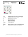
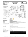
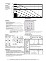
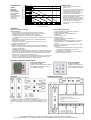
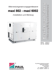
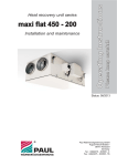
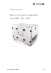
Please keep next to the MVHR unit!
multi 100/150 DC
Operating Instructions
Mechanical Ventilation Heat Recovery Unit
Status: 06.09
Components
suitable for
Passive
House
Dr. Wolfgang Feist
with manual operation
Device-type:
Q multi 100 DC
Q multi 150 DC
®
WÄRMERÜCKGEWINNUNG
Paul Wärmerückgewinnung GmbH
August-Horch-Straße 7
08141 Reinsdorf
Deutschland
Tel.: +49(0)375 - 303505 - 0
Fax: +49(0)375 - 303505 - 55
Contents
Part A Instruction Manual
Page
1
0.
Introduction . .......................................................................................................
1.
1.1
1.2
1.3
1.4
1.5
1.6
1.7
1.8
1.9
Brief description ..................................................................................................
Equipment configuration
Housing, heat insulation, sound absorption
Heat exchanger
Summer box
Ventilators/fans
Filter
Operation Limits .................................................................................................
Combustibility
Anti-freeze
2.
2.1
2.2
Options and additional functions ........................................................................
Options
Additional functions
2
3.
3.1
3.2
3.3
Assembly instructions ........................................................................................
Assembly of the heat recovery device (WRG) – attaching the air ducts
Power supply / Electrical operation .....................................................................
Attachment and maintenance of the condensation discharge hose G ¾”
2
4.
4.1
4.2
4.3
Start-up ..............................................................................................................
Readiness for operation
Setting the air volume flow rate
Adjusting the valves (incoming air and exhaust air)
4
5.
5.1
5.2
Maintenance and repairs by owners (users) ......................................................
General information
Changing filters
5
6.
Maintenance and repairs by technical staff ......................................................
5
1
2
3
Part B Instruction manual for operation
1.
1.1
1.2
1.3
1.4
1.5
1.6
1.7
1.8
1.8.1
1.8.2
1.8.3
1.8.4
1.9
Manual operation ................................................................................................
Ease of use
Description of operating possibilities
Fan stages
Speed monitoring
Draught ventilation
Suitability of chimney .........................................................................................
Filter duration
Control inputs
Digital inputs
Clock timer
Anti-freeze, analogue input
Release relay
Display of the operational and error status .......................................................
Appendices
Appendix 1 Clamping plan for manual operation multi 100/150 DC
Technical Data multi100 DC
Technical Data multi150 DC
Checklist A maintenance work by owners/users
Checklist B by technical staff
Record of air volume flow rate
1
2
3
Status 24.06.09
We reserve the right to make
changes favouring technical
progress.
Instruction manual
multi 100/150 DC
manual operation
0. INTRODUCTION
PLEASE READ THIS MANUAL CAREFULLY BEFORE START-UP!
This manual contains all the required instructions for an optimal assembly of a unit and the heat recovery
device (WRG) of the type multi 100/150 DC. It also serves as a guide for maintenance and customer
service work.
Using this manual, you can learn how to easily use your heat recovery device in as optimal a way as
possible. In case you have to do any work inside the device we recommend taking the advice of the
installation company.
The device is subjected to continuous improvement and further development. It is possible, therefore, that
your device differs slightly from the description.
We hope you enjoy using your WRG multi 100/150 DC.
PLEASE NOTE: Great care has been taken in preparing this manual. However, you are not entitled to any
rights through its use. We reserve the right to modify the content of this manual, partially or completely, at
any time.
1. Brief description
1.1
Equipment design
The compact heat recovery device (WRG) is ready to be connected and consists of an actual heat
recovery device, the control unit and the operating element belonging to it. The WRG is connected to the
control unit with a 3 m long cable. The cable for connecting the operating element to the control unit can be
max. 15 m long and as with the power supply for the control unit, must be provided by the customer.
1.2
Housing, heat insulation, sound absorption
The cabinet is made of galvanised, white powder coated steel sheets with inner heat insulation and
sound absorption (see Technical Data for exact structure).
We recommend attaching one sound absorber each (or 1...2m sound insulated flex hose 125 or 160 in
diameter). The air ducts should be flexible.
1.3
Heat exchanger
The highly efficient reverse flow channel heat exchanger (German and European Patent) has been built in
such a way that the channels (plastic) are arranged in a chessboard pattern and a duplication of the heat
exchange surface compared to plate heat exchangers is thus achieved; the two media (exhaust air and
incoming air) are hermetically separated from each other.
1.4
Summer box
The summer box replaces the heat exchanger package in summer. The two air flow directions pass by
each other without heat transmission in this way.
1.5
Ventilators/fans
The device contains two maintenance-free electronically commutated 48 V DC radial ventilators with
blades bent backwards. When ventilation is normal, a specific energy consumption of 0,36 Wh/m³
(passive house quality certificate) is reached.
The air volume flow rates can be varied by the user. Please observe here, that if there are a few
people and a short duration of stay, less CO2, air moisture and smells are emitted into the room and
the air quantity can thus be intensely reduced. When outside temperatures are cold (dry outside air),
room air conditions that are too dry can be avoided.
1.6
Filters
2 Filters in a Z design of the filter type G 4 (house dust filter) are installed in the device. They are made
out of a mixed cotton/polyester fibre in a cardboard frame. A high grade pollen filter (filter type F 8) can be
used optionally as an incoming air filter. Filter monitoring takes place through the electronic control unit
using checking of duration (see point 5.2).
© Paul Wärmerückgewinnung GmbH • August-Horch-Straße 7 • 08141 Reinsdorf • Deutschland
Tel: +49(0)375-303505-0 • Fax: +49(0)375-303505-55 • E-Mail: [email protected] • Internet: www.paul-lueftung.de
1
Status 24.06.09
We reserve the right to make
changes favouring technical
progress.
Instruction manual
multi 100/150 DC
manual operation
1.7
Operation limits
The WRG has been designed for the suctioning of used air and introduction of fresh, temperate outside air.
Any other usage is contrary to these intentions. The manufacturer is not responsible for damages or
consequences resulting from usage for purposes other than those intended. The device can be used for
ventilation in the living and office areas (limited use in commercial spaces) at air temperatures up to +
40°C and normal air moisture. Explosive and aggressive gases as well as solvents that attack the
materials the device is made of cannot be used on the device. The device must be set up in a frost free
room. A soil heat exchanger is of advantage to pre-heat the external air (winter). If this is not possible,
defroster heating (please enquire) must be connected to it in series.
1.8
Anti-freeze
An anti-freeze switch serves as an anti-freeze measure to protect the device and functions by speed
reduction of the incoming iar ventilator (see instruction manual, operation, Pt. 1.7.3) This frost protection
cannot be used together with a chimney. The anti-freeze element in the device should also be guaranteed
as follows:
a) Defroster heating with independent operation (Option), or
b) Soil heat exchanger (Option). The WRG multi 100/150 DC can additionally be used (option) with an
anti-freeze switch suitable for chimneys.
1.9
Combustibility
The device housing is made up of steel sheets. The installed parts are made of not easily inflammable
polystyrene (Fire type B1). Other components are not easily inflammable or normally inflammable (heat
exchangers, ventilators); the filter with a cardboard frame (combustible) can be classified as a subordinate
component. The device thus complies with regulations stipulated by the buildings authorities.
2. Options and additional functions
2.1
Options (for additional explanations, see the instruction manual for operation)
• Suitability of chimney (additional configuration software)
• Clock timer (can be integrated into the PEHA switch programme analogous to the plastic film
keyboard element)
• External draught ventilation key
2.2
Additional functions (for further explanations, see instruction manual for operation)
• Draught ventilation with external key
• External OFF switch
• Free switch contact
3. Assembly instructions
3.1
Assembly of the heat recovery device (WRG) – connecting the air ducts
The WRG device should preferably be mounted in a vertical position to guarantee a better discharge of the
condensation fluid, but horizontal installation is possible.
PLEASE NOTE: Devices meant for horizontal assembly cannot be mounted vertically and vice-versa. In
the case of horizontal assembly the device should not be placed directly on to cabinets,
but should be attached separately, with the clamps made available for holding it.
ATTENTION:
To enable the condensation fluid to drain off, the WRG device should be mounted with a
slight incline to the escaping air pipe and the rear of the cabinet (towards the
condensation discharge) when being mounted horizontally. This can be achieved by
placing base plates in front of the two lower fastening clamps of the device. Please
make sure it is easily accessible for changing of filters and maintenance.
Connecting the air ducts – rectangular air ducts 205 x 60 as per equipment design
To enable easy assembly, the air duct connections should be made with flexible air hoses. Apart from the
possibility described under point to, you can also to pull a special insulating hose covered with aluminium
over the flexible rectangular hose to ensure good sound absorption (length 1..2m). The air ducts must be
insulated in the following areas with 50 mm insulation:
© Paul Wärmerückgewinnung GmbH • August-Horch-Straße 7 • 08141 Reinsdorf • Deutschland
Tel: +49(0)375-303505-0 • Fax: +49(0)375-303505-55 • E-Mail: [email protected] • Internet: www.paul-lueftung.de
2
Status 24.06.09
We reserve the right to make
changes favouring technical
progress.
•
•
•
•
Instruction manual
multi 100/150 DC
manual operation
Ducts emitting cold air into warm rooms (airtight masking of insulation!)
Ducts emitting warm air into cold rooms, if
available:
Defroster heating
Air heater for subsequent heating of air
3.2
Power supply / Electrical operation
The WRG multi 100/150 DC is connected to the control unit with a 3 m long control cable. The control panel
is connected to a socket with 230 VAC 50 Hz using a mains supply cable, which must be available at the
place where the control unit is being assembled.
Please note:
• The control cables for operating elements and sensors cannot be laid out right next to 230/400
VAC lines (minimum space 20 cm) and cannot be laid out in loops.
• The control unit must be mounted in such a way that heat accumulation is avoided and
accessibility for servicing is ensured. When you are mounting it, please make sure that the
control element is not encased or enclosed ( e.g. „concealed“).
3.3
Connection and maintenance of the condensation discharge hose G ¾”
The condensation discharge hose must
be laid out all over in an inclined position
(min. 5%). The diameter should not be
reduced. The condensation liquid should be
able to drip off freely at the end, so that the
hose is emptied completely. If there is a risk
of rust, this hose must be heated
(accompanying heating hose can be
supplied). If a vertical or horizontal air duct is
mounted on the pipe connected for escaping
air, a condensation discharge outlet must
also be attached at the bottom of it.
Lay out the condensation pipes in a frost free
place!
Fig. 1
Please note: Siphons can dry up!
They should always be filled with water, when:
• the device is being started up
• the siphon makes noises (slurping noises)
• the building’s sewage system emits smells
• air starts flowing out of the siphon
• a dry siphon is recommended and can be supplied (no smell is emitted into the air when it dries
up)
If a low point cannot be avoided when laying out the pipe for escaping air from the device’s connecting pipe
for escaping air to the wall outlet, a further connecting pipe for the transmission of the condensation must be
connected there, since the escaping air is saturated with steam when outside temperatures are cold and
there is precipitation in the form of drops on the inner walls of the pipe. If you plan to attach a sound
absorber on the connecting pipe for escaping air, this must be arched upwards(∩) to protect it from getting
drenched by the condensation flowing back from the pipe for escaping air. The device should be set up in
such a way that the condensation discharge can flow over a long, well inclined stretch.
© Paul Wärmerückgewinnung GmbH • August-Horch-Straße 7 • 08141 Reinsdorf • Deutschland
Tel: +49(0)375-303505-0 • Fax: +49(0)375-303505-55 • E-Mail: [email protected] • Internet: www.paul-lueftung.de
3
Status 24.06.09
We reserve the right to make
changes favouring technical
progress.
Instruction manual
multi 100/150 DC
manual operation
4. Start-up
4.1
Readiness for use
• Establish a connection to the mains
• Fill syphon with water
• Switch device to medium fan speed (e.g. level 5)
4.2
Setting of the air volume flow rate
The air volume rate is set through the ventilator speed. (For factory setting, see Technical Data Characteristic curves-).
In accordance with the pipe layout (loss of pressure in all lines is the same, e.g. 100 Pa) and the required
total volume flow rate, the appropriate characteristic setting for normal ventilation (e.g. 70% or point 5)
must be selected from the technical data of the device and the ventilation speed must be set on the
operating element. The volume flow rate of incoming and exhaust air can be set differently, e.g. when
using a soil heat exchanger the speed of the incoming air ventilator must be increased above the
corrected speed under if necessary (For procedure: see instruction manual for manual operation). The
volume flow rate of the incoming and exhaust air is balanced out through the network of channels.
4.3
Adjusting the valves (incoming air and exhaust air)
• Set ventilators to medium using the operating element
• Adjusting the air volume flow rates on the air valves using the volume flow hood and anemometer
(see the recorded air volume rate)
• Do not set too narrow an air gap on the valve – there will be noises in the air! It is better to decrease
the ventilator speed or reduce the volume flow rate in the pipe itself (install a throttle valve or foam
throttle)
• Adjustment of air volume flow rate on the device (if required). Evenness of exhaust air and incoming
air flow rate (balance adjustment by adjusting the ventilator speed), slightly more exhaust air than
incoming air is possible
• Subsequent adjustment of the valves
• Entry into the enclosed „air volume flow rate records“
5. Maintenance and repairs by owners (users)
5.1
General information
Maintenance of the device for the end user is limited to periodically cleaning the filters and the valves for
incoming and exhaust air. The unit cannot be operated without filters, so, switch off the device first! Users
should change pollen filters right after the period when there is a lot of pollen in the air (the pollen to which
they are allergic). Checking of filters should be carried after 90 days of operation. According to EN DIN
1946-10, filters must be changed every 3 – 6 months. The filters can be bought from PAUL, cleaning the
filters in the WRG device is not possible. Changing or cleaning (warm water with dishwashing liquid) the
filter mats on the exhaust air valves in the exhaust air rooms (e.g.: bathroom, kitchen, WC) should take
place every 2-3 months or as you see appropriate after checking the amount of dirt that has accumulated.
5.2
Changing the filters
Changing of exhaust air and incoming air filters in the heat recovery device should take place when
„change filter“ lights up in the LED display of the operating element.
The ventilator is opened using the two clasps. The filters can be taken out of the filter holder using the grip.
Install the filters according to the prescribed through-flow (marked with the arrow ↑). The door of the
heat recovery device must be closed before starting up the device again.
6. Maintenance and repairs by maintenance staff
Servicing must be carried out at least every 2 years according to DIN 1946/6 Point 6 and includes the
following work:
Filter checking and changing (see above) and cleaning the heat exchanger (WT). Cleaning takes
place according to the amount of dirt that has accumulated, time between servicing is about every 2
© Paul Wärmerückgewinnung GmbH • August-Horch-Straße 7 • 08141 Reinsdorf • Deutschland
Tel: +49(0)375-303505-0 • Fax: +49(0)375-303505-55 • E-Mail: [email protected] • Internet: www.paul-lueftung.de
4
Status 24.06.09
Instruction manual
We reserve the right to make
changes favouring technical
progress.
multi 100/150 DC
manual operation
years (important for maintaining 5 year guarantee claims to the heat exchanger).
Instructions:
1. Disconnect mains supply
2. Open housing door using clasps
3. Remove seals on the heat exchanger and take it out carefully
4. Clean heat exchanger with warm water <50°C by adding dishwashing liquid through the
two air vents, turn the heat exchanger around and repeat the rinsing process, then let it
drain off
5. If there is calcification, spray the heat exchanger surfaces 3 times with vinegar solution from
the air entry side at 20 minute intervals and finally rinse off with water
6. Check the condensation discharge pipe, clean it if necessary
7. Fill the condensation siphon with water
8. Re-assemble the WRG device in the reverse order, close the housing door
9. Connect to mains again
General checking of device:
1. For dirt
2. for electrical safety
When doing this, the outlets for incoming and exhaust air (valves) should be cleaned.
© Paul Wärmerückgewinnung GmbH • August-Horch-Straße 7 • 08141 Reinsdorf • Deutschland
Tel: +49(0)375-303505-0 • Fax: +49(0)375-303505-55 • E-Mail: [email protected] • Internet: www.paul-lueftung.de
5
Status 24.06.09
We reserve the right to make
changes favouring technical
progress.
Operating Instructions
multi 100/150 DC
manual operation
1. Manual operation
1.1
•
•
•
•
•
•
•
•
•
•
Ease of use
7-point speed setting for ventilators and OFF function
Possibility of draught ventilation
Possibility of connecting additional, external, draught ventilation key
External contact for OFF
Clock timer (Option)
Adjustable balance between exhaust air and incoming air ventilator
„only incoming air“ or „only exhaust air“ (operation during summer)
In the case of suitability for chimneys „only exhaust air“ is closed
Monitoring of filter duration
Anti-freeze a) Immediate reduction in the speed of the ventilation fan (not in the case of suitability for
chimneys) from a temperature for escaping air < 2°C onwards
b) Defroster heating with independent operation (Option)
c) Soil heat exchanger (Option)
1.2
Description of operating possibilities
The plastic film keyboard enables a 7-point speed setting for the ventilators with an OFF function. The 7point fan speed control can be implemented both in incoming air and exhaust air operation as well as in
the operational settings „only incoming air“ or „only exhaust air“ (closed in the case of suitability for
chimneys – e.g. when being operated in the summer). The unit can be switched on and off parallel to the
operating element with an external, potential free opener (provided by the customer). A free switch
contact can be used for operating a fan speeds dependent on time. The balance between incoming air
and exhaust air takes place by balancing out using a potentiometer P1.
1.3
Fan speeds
7 fan speeds can be selected using the + / - buttons. The current fan speed is displayed on an LED light
display screen including the selected speed. The fans can be turned off with the (-)- button at speed level
1, the fan speed LEDs are switched off, only the operating type LED remains on. The incoming air fan or
the exhaust air fan can be reduced in the control unit with a balance potentiometer P1 using a corrective
factor. Turning in the –L1 direction means reduction in the speed of the incoming air fan, in the –L2
direction means reduction in the speed of the exhaust air fan. The corrective factor K can amount to a
maximum of 50%. (see Appendix 1 „Terminal connection plan for manual operation multi 100/150 DC“).
1.4
Speed monitoring
If there has been an error, the defective fan is displayed on the operating panel through a blinking LED
(the symbol for incoming or exhaust air blinks). When one fan stops working, the other fan is switched off.
No error message is generated through operation dependent switching off of the fan (anti-freeze).
1.5
Draught ventilation
It is possible to activate the draught ventilation either on the plastic film keyboard or through one or
several external keys attached to the control panel (see Appendix 1 „ Terminal connection plan for manual
operation atmos 175 DC).
Function: When the function „draught ventilation“ has been activated, point 7 is selected for 15 minutes
and the corresponding LED fan speed 7 is displayed. The operation type is set to incoming and exhaust
air. After the draught ventilation time is over the control unit activates the previously set state. If a key is
pressed during the draught ventilation period, the corresponding operation type is stopped and the
draught ventilation ends. If key for draught ventilation is pressed again during the draught ventilation time
the draught ventilation is deactivated and the control unit sets the previous operating state again. The
draught ventilation function is shown visually by lighting up of the fan speeds LED 7 and the LED key for
draught ventilation.
© Paul Wärmerückgewinnung GmbH • August-Horch-Straße 7 • 08141 Reinsdorf • Deutschland
Tel: +49(0)375-303505-0 • Fax: +49(0)375-303505-55 • E-Mail: [email protected] • Internet: www.paul-lueftung.de
1
Status 24.06.09
We reserve the right to make
changes favouring technical
progress.
Operating Instructions
multi 100/150 DC
manual operation
1.6
Suitability for chimneys
The simultaneous operation of chimney and ventilator units requires an increase in safety requirements.
This optional function (request according to order form) is activated by the supplier using a software
configuration. In the case of active suitability for chimneys, the button „exhaust air operation“ does not
function, when you press it, the corresponding LED blinks briefly 3x. The anti-freeze (temperature of
escaping air < 2°C) is ensured by the speed reduction of both fans, if necessary until the device comes to
a halt. When regulating to speed zero the fans remain off for 2 hours. After the 2 hours are over the fans
run at the selected speed again. The temperature conditions are checked again and if necessary
regulated up to the zero point again.
The set fan speed remains active. By selecting draught ventilation, a new fan speed or switching the mains
voltage on again during the waiting period, the fans can be re-started again.
The options „Defroster heating“ or „soil heat exchanger“ are necessary for keeping the device free of frost
when operating it in a way that is suitable for chimneys.
1.7
Filter duration
An operating hour counter has been integrated into the control unit for checking the filter duration. The
pre-set filter duration is 90 days. Longer filter durations can optionally be set on the control panel using a
DIP switch S2 (see Appendix 1 „Clamping plan for manual operation multi 100/150 DC“). Please note:
Disconnect the device from mains before intervention inside the control unit!
1.8
Control inputs
1.8.1
Digital inputs
Input X0.1/3: Ventilation OFF: Connection between clamps 1 and 3 closed
Input X0.2/3: Ventilation ON: Connection between clamps 2 and 3 closed
Input X1.1/2: Input for an external control device OFF (EMERGENCY-OFF)(-Control panel-)
Input X1.3/4: Input for draught ventilation for external keys (-control panel-)
Input X4.1/2: Input free switch contact (-external operating element-)
(see Appendix 1 „Clamping plan for manual operation multi 100/150 DC“)
1.8.2 Clock timer, free switch contact
This function serves to provide a time dependent operation for an additional fan speed. A digital input is
evaluated for a potential free timer contact. (e.g. during an active timer period by the second operating level
either an increased or a reduced fan speed can be selected). If the contact is closed, any fan speed can be
selected. If the contact is open, the previous fan speed remains. If the contact is closed again depending
on the time of day, the previous speed selected when the contact was closed runs.
The second operating level (clock timer active) is shown visually through only one LED display for the
selected fan speed. The optional clock timer can be set separately for every day of the week (week clock
timer).
1.8.3 Anti-freeze, analogue input
This input serves the purpose of evaluating the temperature of the escaping air with an NTC sensor. The
anti-freeze element in the device is guaranteed in this way. When the temperature of the escaping air is
below 2°C, the incoming air ventilator is reduced slowly. If the amount of heat in the escaping air is
sufficient there is thus an imbalance with the reduced speed of the incoming air ventilator. The
temperature of the escaping air will then, as a rule, set itself to 2°C or more. If the temperature of the
escaping air permanently remains below 2°C, the speed of the incoming air ventilator is reduced until the
device is switched off and the incoming air ventilator finally switches itself off.
If the temperature of the escaping air increases to more than 3°C, the speed of the incoming air ventilator
is again increased to the same nominal speed.
1.8.4 Release relay
This potential-free change-over contact serves the purpose of activating/deactivating unit specific
ventilation components such as the defroster heating, for example.
© Paul Wärmerückgewinnung GmbH • August-Horch-Straße 7 • 08141 Reinsdorf • Deutschland
Tel: +49(0)375-303505-0 • Fax: +49(0)375-303505-55 • E-Mail: [email protected] • Internet: www.paul-lueftung.de
2
Status 24.06.09
Operating Instructions
We reserve the right to make
changes favouring technical
progress.
1.9
multi 100/150 DC
manual operation
Display of operational and error status
Display
L1 – L7
L1 – L7
L1 + L7 lights
L8
L8 blinks
L9
L10 blinks
L11
L11 blinks
L12
L12 blinks
Function / significance
Fan speed, first operating level (also for timer with inactive switching time)
Fan speed, second operating level (with timer and active switching time)
External switching function „device „OFF“ is activated
Operating type „incoming and exhaust air“
Disturbance to escaping air sensor
Operating type „draught ventilation“
Display of pre-selected filter duration ends
Operating type „only exhaust air“
Exhaust air ventilator fails
Operating type „only incoming air“
Incoming air ventilator fails
Operation
Function / significance
T1, T2
T3, T6, T7
T4
T5
Modification to the fan speed
Selection of the operating type: incoming and exhaust air, exhaust, incoming
Push button key
Resetting the filter duration (configuration after filter duration is over is
possible)
© Paul Wärmerückgewinnung GmbH • August-Horch-Straße 7 • 08141 Reinsdorf • Deutschland
Tel: +49(0)375-303505-0 • Fax: +49(0)375-303505-55 • E-Mail: [email protected] • Internet: www.paul-lueftung.de
3
Status 05.06.09
Technical data
We reserve the right to make
changes favouring technical
progress.
Heat recovery device
multi 100 DC
Equipment design:
Heat recovery components:
Components
suitable for
Passive
House
Dr. Wolfgang Feist
Heat exchanger box:
Ventilators:
Filters:
Material: plastic
48 V DC (DC radial ventilator)
F ilter type: G4 (incoming air/exhaust air)
Option: pollen filter F8 (incoming air) – increased pressure loss
Galvanised steel sheet, powder coated, white, double sound absorption, heat insulated,
heat bridge free
Hose nozzle for condensation discharge pipe 10 / 2
Summer box or only exhaust air operation (for manual operation)
LxWxD (in mm): 340x300x80
230 V, 50 Hz, ready to connect
IP 44 ((Device)
IP 20 (Control unit)
I (as per EN 60335)
- mains supply cable : provided by customer
- control cable between WRG and control device: 3m
- 4 wire, insulated control pipe IYSTY 2x2x0, 6 between control device and operating
element: max. 15 m, provided by customer
35 kg
max. 40 °C
Cabinet:
Condensation discharge pipe:
Summer operation:
Central control device:
Electrical connection:
Protection type:
Protection class:
Cable length:
Weight:
Operation limits:
Operating data:
Power input:
Volume flow rate:
Degree of heat availability:
Sound pressure level:
as per
DIN EN ISO 3743-1
max. 41 W
30 to 130 m³/h - 100 m³/h (at 100 Pa)
approx 85... 98%1)
Fan speed
Level 1
Level 3
Level 5
Level 7
Sound pressure level (3m interval in open space)
22,3 dB(A)
24,2 dB(A)
26,5 dB(A)
29,1 dB(A)
© Paul Wärmerückgewinnung GmbH • August-Horch-Straße 7 • 08141 Reinsdorf • Deutschland
Tel: +49(0)375-303505-0 • Fax: +49(0)375-303505-55 • E-Mail: [email protected] • Internet: www.paul-lueftung.de
Characteristic
curve:
250
level 7
Attention!
level 6
200
Increase in pressure [Pa]
Characteristic
curves can differ
due to permitted
tolerances!
(e.g. according to the
manufacturer, 10%
for fans, 5%
transformers!)
level 5
150
level 4
100
level 3
50
level 2
level 1
10 W
11 W
13 W
16 W
23 W
30 W
41 W
0
0
20
40
60
80
100
120
140
Volume flow rate [m³/h]
Operation:
Manual operation
• 7-point speed setting of the ventilators and OFF function
• Possibility of draught ventilation
• Connection possibility for addition external draught ventilation key
• External contact for OFF
• Clock timer (optional)
• Condensation connection pipe
• Chimney suitability (Option – additional configuration software)
• Balance between exhaust air and incoming air ventilator can be
adjusted
• „only incoming air“ or „ only exhaust air“ (summer operation)
• In the case of chimney suitability „only exhaust air“ is closed
• Monitoring of filter duration
• Anti-freeze:
a) Immediate speed reduction of the incoming air
ventilator (not in case of chimney suitability) from an
escaping air temperature < 2°C
b) Defroster heating with independent operation
(option)
c) Soil heat exchanger (Option)
Operating element (control unit):
Plastic film keyboard
for manual operation in the illuminated button of the PEHA switch
programme
(LxBxT in mm: 80x80x12) Cable: IYSTY 2x2x0,6, max. 15 m,
provided by customes
Designs:
Installation versions:
horizontal and vertical (preferably)
Can be integrated into furniture, e.g. kitchens/bathroom cabinets
If installation is horizontal, the exhaust air/ escaping air connections must
always lie at the bottom! The hinge side can be supplied at the top or at the
bottom for vertical designs (1 and 2) left or right, for horizontal designs (3 and 4)
Please note:
• The device must be set up frost free, if possible >10 °C.
• The control unit must be mounted in such a way that heat
accumulation is avoided and accessibility for servicing is ensured.
• Control cables for operating elements and sensors cannot be laid
out parallel to 230/400 VAC lines (minimum interval 20 cm) and also
cannot be laid out in loops.
• There is an additional module for monitoring low pressure for
simultaneous operation with fireplaces, with a switching off function
for the ventilation device and/or the evaporation hood with a
connection for escaping ais
© Paul Wärmerückgewinnung GmbH • August-Horch-Straße 7 • 08141 Reinsdorf • Deutschland
Tel: +49(0)375-303505-0 • Fax: +49(0)375-303505-55 • E-Mail: [email protected] • Internet: www.paul-lueftung.de
Status 05.06.09
Technical data
We reserve the right to make
changes favouring technical
progress.
Heat recovery device
multi 150 DC
Equipment design:
Heat recovery components:
Components
suitable for
Passive
House
Dr. Wolfgang Feist
Heat exchanger box:
Ventilators:
Filters:
Material: plastic
48 V DC (DC radial ventilator)
F ilter type: G4 (incoming air/exhaust air)
Option: pollen filter F8 (incoming air) – increased pressure loss
Galvanised steel sheet, powder coated, white, double sound absorption, heat insulated,
heat bridge free
Hose nozzle for condensation discharge pipe 10 / 2
Summer box or only exhaust air operation (for manual operation)
LxWxD (in mm): 340x300x80, or 340x300x140 with option defreezing- and
heatingsystem
230 V, 50 Hz, ready to connect
IP 44 ((Device)
IP 20 (Control unit)
I (as per EN 60335)
- mains supply cable : provided by customer
- control cable between WRG and control device: 3m
- 4 wire, insulated control pipe IYSTY 2x2x0, 6 between control device and operating
element: max. 15 m, provided by customer
35 kg
max. 40 °C
Cabinet:
Condensation discharge pipe:
Summer operation:
Central control device:
Electrical connection:
Protection type:
Protection class:
Cable length:
Weight:
Operation limits:
Operating data:
Power input:
Volume flow rate:
Degree of heat availability:
Sound pressure level:
as per
DIN EN ISO 3743-1
max. 82 W
30 to 180 m³/h - 150 m³/h (at 100 Pa)
approx 85... 98%1)
Fan speed
Level 1
Level 3
Level 5
Level 7
Sound pressure level (3m interval in open space)
26 dB(A)
31 dB(A)
37 dB(A)
38 dB(A)
© Paul Wärmerückgewinnung GmbH • August-Horch-Straße 7 • 08141 Reinsdorf • Deutschland
Tel: +49(0)375-303505-0 • Fax: +49(0)375-303505-55 • E-Mail: [email protected] • Internet: www.paul-lueftung.de
Characteristic
curve:
Characteristic
curves can differ
due to permitted
tolerances!
(e.g. according to the
manufacturer, 10%
for fans, 5%
transformers!)
level 7, ca. 90-100%
• The device must be set up frost free, if
350
possible >10 °C.
• The control unit must be mounted in such a
level 6, ca. 80%
Increase in pressure [Pa]
Attention!
Please note:
400
300
level 5, ca. 70%
250
•
200
level 4, ca. 60%
150
•
level 3, ca. 50%
100
level 2, ca. 40%
50
level 1, ca. 30%
10 W
0
0
20
40
13 W
60
16 W
80
39 W
26 W
100
120
57 W
140
160
82 W
way that heat accumulation is avoided and
accessibility for servicing is ensured.
Control cables for operating elements and
sensors cannot be laid out parallel to
230/400 VAC lines (minimum interval 20 cm)
and also cannot be laid out in loops.
There is an additional module for monitoring
low pressure for simultaneous operation
with fireplaces, with a switching off function
for the ventilation device and/or the
evaporation hood with a connection for
escaping ais
180
Volume flow rate [m³/h]
Operation:
Version 1: Automatic operation
Version 2: Manual operation
Standard functions
• 8 time programmes, any programme order possible on weekdays
• Manual operation of the fan speeds (off, minimum, normal, maximum)
• Operating element can be installed freely in the living area
• Several push buttons can be connected to the operating element
• Programming of the fan speeds in 1% steps (30-100 % of the maximum fan speed
is possible)
• Balance between exhaust air and incoming air ventilators is adjustable
• Monitoring of filter duration
• Protection from ice for warm water heat exchanger connected in series
• Standby switch, voltage under 2 W
Options (at an additional cost)
• Operation through an electric regulating valve (sucking in of the outside air
directly or through the soil heat exchanger) or a sole defroster (sole/air WT for
conditioning of external air)
• Operating defroster heating
• Volume flow rate constant regulation (the volume flow of the incoming and exhaust air
are continuously monitored and balanced out, and are thus suitable for the chimney)
• Operating of a heating circuit (e.g. heating circuit pump or electric subsequent heat
exchanger up to 2.1 kW – also with reduction at night
• The device can be operated using several operating elements (e.g. one at the place it
is set up, one in the living area). If a heat exchanger is used in the process, room
temperature setting takes place with the first operating element.
• 7-point speed setting of ventilators and OFF function
• Draught ventilation possibility
• Connection possibility for an additional draught
ventilation key
• External contact for OFF
• Clock timer (option)
• Suitability for chimneys (Option additional
configuration software)
• Balance between exhaust air and incoming air is adjustable
• „only incoming air“ or - „only exhaust air“ (Summer
operation)
• In the case of chimney suitability „only exhaust air“ is closed
• Monitoring of filter duration
• Anti-freeze:
a) Immediate speed reduction of the incoming air ventilator
(not for chimney suitability) from an escaping air
temperature of < 2°C onwards
b) Defroster heating with independent operation (Option)
c) Soil heat exchanger (Option)
Operating elements (control units):
Comfort operating element
for automatic operation
(LxWxD in mm: 158x125x32); at the low
point Cable: IYSTY 2x2x0, 6, max. 15
m, provided by customer
Plastic film keyboard
for manual operation
(LxWxD in mm: 80x80x12);
Cable: IYSTY 2x2x0, 6, max.
15 m, provided by customer
Designs:
Installation versions:
horizontal and vertical (preferably)
Can be integrated into furniture, e.g. kitchens/bathroom cabinets
If installation is horizontal, the exhaust air/ escaping air connections must
always lie at the bottom! The hinge side can be supplied at the top or at the
bottom for vertical designs (1 and 2) left or right, for horizontal designs (3 and
4)
© Paul Wärmerückgewinnung GmbH • August-Horch-Straße 7 • 08141 Reinsdorf • Deutschland
Tel: +49(0)375-303505-0 • Fax: +49(0)375-303505-55 • E-Mail: [email protected] • Internet: www.paul-lueftung.de
Checklist A
for maintenance work
by the owner / user
Issue 19/05/09
Subject to change in the interest
of technical progress.
maintenance work
1. change both filters in the WRG device: Enter the date every quarterly
Quarterly
Year
I
II
III
IV
III
IV
III
IV
200...
201...
201...
201...
201...
2. Clean filters in exhaust air valves: Enter date every quarterly
Quarterly
Year
I
II
200...
201...
201...
201...
201...
3. Change pre-filters in fresh air pipe
(Suctioning in of outside air – also in the soil heat exchanger)
Quarterly
Year
I
II
200...
201...
201...
201...
201...
4. Exhaust hood
- Clean grease filters every 6 -8 weeks with hot water for rinsing
- Change activated carbon filter (only in the case of a circulating air hood) every 4 months
Quarterly
Jahr
I
II
III
IV
200...
201...
201...
201...
201...
Simplified formula for determining heat recovery rate η:
t −t
η = SUP INT
t EXT − t INT
Legend: t INT - Intake air temperature
Notes: The warranty expires, if
t EXT - Extract air temperature
tSUP - Supply air temperature
Note:
The air temperatures are to be
measured in the center of the
air lines at the equipment!
• filter change is made not at least within the double standard time
specified above
• no original PAUL filters are used
© Paul Wärmerückgewinnung GmbH • August-Horch-Straße 7 • 08141 Reinsdorf • Deutschland
Tel: +49(0)375-303505-0 • Fax: +49(0)375-303505-55 • E-Mail: [email protected] • Internet: www.paul-lueftung.de
Issue 19/05/09
Subject to change in the interest
of technical progress.
Checklist B
for maintenance work
by technical staff
Maintenance work
− Inspection of the ventilation unit every 2 years as per DIN 1946/Part 6 Pt.6 and DIN 1946/Part 2, Pt.7
as per. VDI 6022 (4/2006) point 5.3.2 must take place hygiene inspections with RLT plants without
humidification in the distance from 3 years (… with humidification every 2 years)
− Please enter: Year, Date, Name
− Remarks on condition → informal record
201...
201...
201...
201...
201...
1. Clean heat exchanger with warm water
< 50°C and washing-up liquid – in case of
calcification: vinegar solution
Air-to-air heat transducers are as per DIN
1946/6 to clean (point 12,3 (3)) annually
2. Check all filters for contamination,
moisture, tightness and corrosion;
replace where necessary
a in the MVHR unit
b at outdoor air intake (pre-filter – e.g.
gable wall or ground heat exchanger)
c at extract air valves
d check filter change intervals by
e
3.
4.
a
b
c
d
5.
a
b
c
d
6.
a
b
7.
8.
a
b
c
9.
a
b
c
d
e
f
inspecting the records of the tenant /
owner
record any filter change in writing
Check intake air ducts for contamination
on a random basis (also in the ground
heat exchanger)
Check silencers / sound attenuators
at the MVHR unit
in the ventilation system (if accessible)
at overflow passages/openings (e.g.
doors, partition walls) (if any)
clean where necessary
Check duct heaters (frost protection
and back-up duct heater)
clean to remove dirt where necessary
functional check
Thermal protection switch function
check heat insulation (visual)
Check valve settings (air flow rate)
as projected
or according to different user experience
Clean valves
condensate drain (U bend clogged?)
check water level in U bend
condensate pan
Condensate drainage (siphon clogs?)
Water filling in the siphon examine
Water inlet (if available)
Check airtightness in MVHR unit
pull the mains plug
disconnect the extract air fan
electrically (put it out of circuit)
disconnect the extract air duct from the
MVHR unit.
connect the mains plug & switch on the
intake air fan
Exhaust air duct from the MHRV unit
separate
Power supply plugs attach + fresh air fan
switch on
© Paul Wärmerückgewinnung GmbH • August-Horch-Straße 7 • 08141 Reinsdorf • Deutschland
Tel: +49(0)375-303505-0 • Fax: +49(0)375-303505-55 • E-Mail: [email protected] • Internet: www.paul-lueftung.de
g in the ventilating outlet no air movement
may be noticeable - inspection result
h Bypass slidegate valve tightness (in WT10.
a
b
c
d
e
f
g
h
11.
a
b
12.
a
b
13.
a
b
c
d
14.
a
b
c
d
15.
a
b
c
16.
a
b
c
d
e
f
g
h
i
k
box remove heading) only with type „thermos “
Check:
electrical connections (contacts)
fan control
boost switch
filter indicator
other control equipment
clean flow sensors
fan speed balance VSUP = VEXT
Differential pressure guard, annually
Check ventilation fans
bearing noise (charred grease)
imbalance
Check ventilation system for tightness
and corrosion (visual examination)
assembly joints
flexible lines
Check insulation (visual examination)
damage
moisture penetration
connection point at MVHR unit
line to valve connection
Check fire dampers (if any)
inspect test report
latch and trigger mechanism; check for
contamination and reversible function
change trigger element and check for
smooth action
functional check of position indicator
Measurements and recording of
measured data
power input of MVHR unit (without
heating) at operating speed
temperature at MVHR duct socket:
• intake air
• supply air
• extract air
• exhaust air
temperature at
- supply air valve
- exhaust air valve
Maintenance cost & expenses
maintenance [h]
hourly rate [€/h]
a x b [€]
mileage actually run
mileage allowance [€/mile]
d x e [€]
travel time
hourly rate for travel [€/h]
gxh
total: c + f + i
Monthly charge [€/month]
for 2-year interval
The following maintenance items are compulsory:
1, 2, 3, 5, 7, 8, 10, 14 (for multi-family houses), 15, 16 = simple maintenance
© Paul Wärmerückgewinnung GmbH • August-Horch-Straße 7 • 08141 Reinsdorf • Deutschland
Tel: +49(0)375-303505-0 • Fax: +49(0)375-303505-55 • E-Mail: [email protected] • Internet: www.paul-lueftung.de
Issue 20/05/09
Subject to change in the
interest of technical progress.
Air Flow Report
(Operating condition and functional check)1)
Address
Date:
Name:
Street:
Town/city:
Tel:
Device No.
Measuring device used:
Control unit no.
MVHR-Type
Description of disturbances
during measurement:
Year of construction
Inside temperature 2):
Outside temperature
2)
:
2)
Weather :
Filter condition when measuring
clean
Used approx.....days
Very dirty
supply air supply air
Fan speed ratio
clean extract/supply air:
Project Data
m³/h
m³/s
...........................
Ventilation step:
%
Measurement data
m³/h
m³/s
Valve
mm
Project Data
m³/h
m³/s
Ventilation step:
%
Measurement data
m³/h
m³/s
Valve
mm
Supply air
No.
Room description
Extract air
No.
Room description
Pel =
W (2 fans)
The control system of the MVHR unit has been inspected.
1) The volumetric air flow is measured during normal MVHR operation 3) as agreed.
2) according to draft prEN 14134, item 7.3.1.5
3) according to prEN 14134, item 7.4.1. b) end
Ö The user has been instructed on the hygienic
requirements for the operation of the MVHR unit
ÖNo parts other than genuine PAUL parts (e.g. filters)
shall be used, otherwise the warranty will be void
ÖThe warranty period starts with the start-up of the
system (date of commissioning)
signatures..................................................................................
start-up personnel
user
© Paul Wärmerückgewinnung GmbH • August-Horch-Straße 7 • 08141 Reinsdorf • Deutschland
Tel: +49(0)375-303505-0 • Fax: +49(0)375-303505-55 • E-Mail: [email protected] • Internet: www.paul-lueftung.de