1
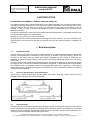
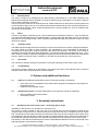
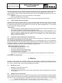
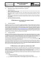
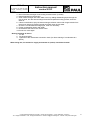
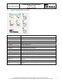
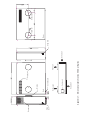
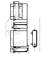
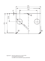
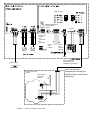
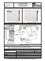
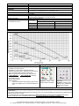
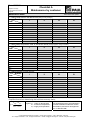
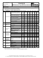
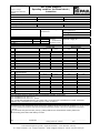
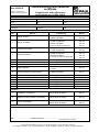
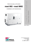
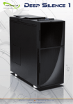
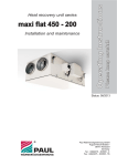
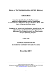
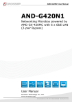
Standard (supply and exract grille) for decentral systems Please keep carefuly! ventos 50 DC Operating Instructions Decentral heat recovery unit Status: 03.2013 Special construction (supply and / or extract pipe connection and in combination with grille) for isolated solutions Paul Wärmerückgewinnung GmbH August-Horch-Straße 7 08141 Reinsdorf Germany Tel.: +49(0)375 - 303505 - 0 Fax: +49(0)375 - 303505 - 55 Contents Part A Instruction Manual Page 1 0. Introduction.......................................................................................................... 1. 1.1 1.2 1.3 1.4 1.5 1.6 1.7 1.8 Brief description…............................................................................................... Equipment configuration Housing, heat insulation, sound absorption Heat exchanger Ventilators/fans………………………………………………………………………... Filters Operation limits Anti-freeze Combustibility 1 2. 2.1 2.2 Options and additional functions......................................................................... Options Additional functions 2 3. 3.1 3.2 3.3 Assembly instructions.......................................................................................... Assembly of the heat recovery unit (HRU) – connecting the air ducts Power supply / Electrical operation…………………………………………………. Connection of the condensation discharge hose 2 4. 4.1 4.2 4.3 Start-up................................................................................................................ Readiness for use Setting of the air volume flow Adjusting the valves (supply air and extract air), if any…………......................... 3 5. 5.1 5.2 Maintenance and repairs by owners (users)……………..................................... General information Changing the filters 4 6. Maintenance and repairs by maintenance staff.................................................. 4 2 3 4 Part B Instruction manual for operation 1. 1.1 1.2 1.3 1.4 1.5 1.6 1.7 1.7.1 1.7.2 1.7.3 1.7.4 1.8 1.9 Manual operation…............................................................................................. Ease of use Description of operating possibilities Fan speeds Speed monitoring Boost ventilation Filter duration………………………………………………………………………….. Control inputs Digital inputs Clock timer Anti-freeze, analogue input Release relay Drain pan Display of the operational and error status.......................................................... Appendices Appendix 1 Dimensional sketch ventos 50 DC with ventilation slots Appendix 2 Dimensional sketch ventos 50 DC with adapters for supply air and extract air Appendix 3 Mounting dimensions ventos 50 DC for equipment mounting and for intake air and extract air pipe penetration Appendix 4 Terminal connection ventos 50 DC Technical data Check List A Maintenance Works of the User Check List B Maintenance Works of Qualified Personnel Air Flow Report Commissioning and Handover Certificate CE Declaration of Conformity 1 2 3 Status 07.03.12 We reserve the right to make changes favouring technical progress. Instruction manual ventos 50 DC 0. INTRODUCTION PLEASE READ THIS MANUAL CAREFULLY BEFORE START-UP! This manual contains all the required instructions for an optimal assembly of a unit and the heat recovery unit (HRU) of the type ventos 50 DC. It also serves as a guide for maintenance and customer service work. Using this manual, you can learn how to easily use your heat recovery device in as optimal a way as possible. In case you have to do any work inside the device we recommend taking the advice of the installation company. The device is subjected to continuous improvement and further development. It is possible, therefore, that your device differs slightly from the description. We hope you enjoy using your HRU ventos 50 DC. PLEASE NOTE: Great care has been taken in preparing this manual. However, you are not entitled to any rights through its use. We reserve the right to modify the content of this manual, partially or completely, at any time. 1. Brief description 1.1 Equipment design The heat recovery unit ventos 50 DC was specifically designed as a decentralized ventilation unit with heat recovery and development is provided for wall mounting. It consists of the heat recovery device, the controller (in the device) and the control panel (either integrated into the housing or external to the installation in the PEHA-switch program). The heat recovery system is equipped with plug in a 2.5 m long power cable. The HRU ventos 50 DC is produced by default with supply and extract air grilles and on demand with spigots for supply air and / or extract air for different applications. In Appendix 1 " Dimensional sketch ventos 50 DC with ventilation slots" the standard model for a distributed application and in Appendix 2 " Dimensional sketch ventos 50 DC with adapters for supply air and extract air " is the variant alone solution for ventilation of adjacent spaces depicted. 1.2 Housing, heat insulation, sound absorption The housing is made of galvanized, powder-coated steel sheet, white with internal heat and sound insulation with insulating and cushioning foam mat. 1.3 Heat exchanger The highly efficient reverse flow channel heat exchanger (German and European Patent) has been built in such a way that the channels (plastic) are arranged in a chessboard pattern and a duplication of the heat exchange surface compared to plate heat exchangers is thus achieved; the two media (exhaust air and incoming air) are hermetically separated from each other. © Paul Wärmerückgewinnung GmbH • August-Horch-Straße 7 • 08141 Reinsdorf • Germany Tel: +49(0)375-303505-0 • Fax: +49(0)375-303505-55 • E-Mail: [email protected] • Internet: www.paul-lueftung.de 1 Status 07.03.12 We reserve the right to make changes favouring technical progress. 1.4 Instruction manual ventos 50 DC Ventilators/fans The device contains two maintenance-free electronically commutated 48 V DC radial ventilators with blades bent backwards. When ventilation is normal, a specific energy consumption of 0,44 Wh/m³ (passive house quality certificate) is reached. The air volume flow rates can be varied by the user. Please observe here, that if there are a few people and a short duration of stay, less CO2, air moisture and smells are emitted into the room and the air quantity can thus be intensely reduced. When outside temperatures are cold (dry outside air), room air conditions that are too dry can be avoided. 1.5 Filters 2 Filters in a Z design of the filter type G 4 (house dust filter) are installed in the device. They are made out of a mixed cotton/polyester fibre in a cardboard frame. A high grade pollen filter (filter type F 8) can be used optionally as an incoming air filter. Filter monitoring takes place through the electronic control unit using checking of duration. 1.6 Operation limits The WRG has been designed for the suctioning of used air and introduction of fresh, temperate outside air. Any other usage is contrary to these intentions. The manufacturer is not responsible for damages or consequences resulting from usage for purposes other than those intended. The device can be used for ventilation in the living and office areas (limited use in commercial spaces) at air temperatures up to + 40°C and normal air moisture. Explosive and aggressive gases as well as solvents that attack the materials the device is made of cannot be used on the device. The device must be set up in a frost free room. 1.7 Anti-freeze The unit has an auxiliary energy frost protection circuit (see operating manual control, point 1.8.3). 1.8 Combustibility The device housing is made up of steel sheets. The fixtures are made of fire-retardant foam cushioning material to DIN 75200 (requirements for fire) are satisfied. 2. Options and additional functions 2.1 Options (for additional explanations, see the instruction manual for operation) • • 2.2 Clock timer (can be integrated into the PEHA switch programme analogous to the plastic film keyboard element) External boost ventilation switch Additional functions (for further explanations, see instruction manual for operation) • • Boost ventilation with external switch Free switch contact 3. Assembly instructions 3.1 Assembly of the heat recovery unit – connecting the air ducts Installation of the device is only possible in a frost-free room! The device is mainly installed on the inner side of an outside wall; just two boreholes provided by the customer (with core bit Ø 150 mm, distance 483 mm) having exact size have to be planned on the outside wall. The wall duct of the supply and extract air tube (every DN 125) has to be isolated. The air pipes which are installed into the wall have to be fixed centrically per wedge shaped pieces. After that the space has to be packed with foamed material with non-oppressive polyurethane foam (2k-foam) and to close airtight. The fixation on the wall will be effected per 3 pieces of threaded bars M6 which have to be anchored in the wall appropriately to hold the device (22kg). © Paul Wärmerückgewinnung GmbH • August-Horch-Straße 7 • 08141 Reinsdorf • Germany Tel: +49(0)375-303505-0 • Fax: +49(0)375-303505-55 • E-Mail: [email protected] • Internet: www.paul-lueftung.de 2 Status 07.03.12 We reserve the right to make changes favouring technical progress. Instruction manual ventos 50 DC The mounting dimensions for the fixation of the device and the holes for the pipes are outlined in appendix 3 “Mounting dimensions ventos 50 DC for fixation of the device and the supply and exhaust air tube”. The air pipes, by using the HRU as special construction, have to be isolated with minimum 50 mm in the following sectors: • Cold air carrying lines in warm rooms (isolation to mask airtight) • Warm air carrying lines in cold rooms A weather protection grid is to insert from the outer surface at the supply and extract air duct. 3.2 Power supply / Electrical operation The HRU ventos 50 DC is ready to plug in a 2.5 m long power cable supplied. In the vicinity of the heat recovery with an outlet 230VAC 50 Hz power supply must be provided. The use of heat recovery by means of membrane keyboard that comes standard on the device top surface-integrated plan, or is a special version built into an external wall outlets. Please note: • The control cables for operating elements and sensors cannot be laid out right next to 230/400 VAC lines (minimum space 20 cm) and cannot be laid out in loops. • The common operation of heat-producing appliances and ventilation systems dependent on the indoor air requires a suitable safety device (differential pressure switch) or a plant-specific device, when a dangerous negative pressure builds up in the installation room of the heat-producing appliance during the operation. 3.3 Connection of the condensation discharge hose The condensate is collected in the drain pan and can be done manually to be drained into a container. There is also a condensate drain via a hose possible. The condensation discharge hose must be laid out all over in an inclined position (min. 5%). The diameter should not be reduced. The condensation liquid should be able to drip off freely at the end, so that the hose is emptied completely. If a vertical or horizontal air duct is mounted on the pipe connected for exhaust air, a condensation discharge outlet must also be attached at the bottom of it. Please note: Siphons can dry up! They should always be filled with water, when: • the device is being started up • the siphon makes noises (slurping noises) • the building’s sewage system emits smells • air starts flowing out of the siphon • a dry siphon is recommended and can be supplied (no smell is emitted into the air when it dries up) Condensate line lay frost-free! 4. Start-up According to DIN 1946-6, the ventilation system is left permanently in operation, excluding periods of maintenance and repair work. For the period of absence, the ventilation system was in the lowest fan level (L1 = Level 1 position of the control unit keypad lights) are operated. 4.1 Readiness for use • • • 4.2 Establish a connection to the mains Condensate drain valve close At the end of condensate hose to fill the system-side trap with water (condensate drain valve open on the device!) Setting of the air volume flow When using the heat recovery as an isolated variant (housing version with adapters to supply adjacent rooms), air flow rate is preset on the ventilator output (default: see technical data equipment characteristics). The flow of incoming and outgoing air is adjusted via the sewer system and the balance of compensation © Paul Wärmerückgewinnung GmbH • August-Horch-Straße 7 • 08141 Reinsdorf • Germany Tel: +49(0)375-303505-0 • Fax: +49(0)375-303505-55 • E-Mail: [email protected] • Internet: www.paul-lueftung.de 3 Status 07.03.12 We reserve the right to make changes favouring technical progress. Instruction manual ventos 50 DC (see operating instructions, 1.3) and can be controlled in 7 levels (keypad). 4.3 Adjusting the valves (supply air and extract air), if present • • • • • • Control set to level 5 Adjusting the air volume flow rates on the air valves using the volume flow hood and anemometer (see the recorded air volume rate) Do not set too narrow an air gap on the valve – there will be noises in the air! It is better to decrease the ventilator speed or reduce the volume flow rate in the pipe itself (install a throttle valve or foam throttle) Adjustment of air volume flow rate on the device (if required). Evenness of extract air and supply air flow rate (balance adjustment by adjusting the ventilator speed), slightly more extract air than supply air is possible Subsequent adjustment of the valves Entry into the enclosed „air flow report“ 5. Maintenance and repairs by owners (users) (See Checklist A) 5.1 General information Maintenance of the device for the end user is limited to periodically cleaning the filters and the valves for supply and extract air. The unit cannot be operated without filters, so, switch off the device first! Users should change pollen filters right after the period when there is a lot of pollen in the air (the pollen to which they are allergic). Checking of filters should be carried after 90 days of operation. According to EN DIN 1946-10, filters must be changed every 3 – 6 months. The filters can be directly ordered from the company Paul Wärmerückgewinnung GmbH or via www.paul-lueftung-shop.de., cleaning the filters in the HRU is not possible. Changing or cleaning (warm water with dishwashing liquid) the filter mats on the extract air valves in the extract air rooms (e.g.: bathroom, kitchen, WC) should take place every 2-3 months or as you see appropriate after checking the amount of dirt that has accumulated. 5.2 Changing the filters Changing of extract air and intake air filters in the heat recovery device should take place when „change filter“ lights up in the LED display of the operating element. For this purpose, the housing cover by pressing on the bottom is to remove the casing wall pages is snap-snap closures and gently lifting (see Appendix 1 or Appendix 2 depending on the existing housing design). After that the insulating mat of the housing cover carefully from the heat exchanger on the remaining, glued part of the insulation to be removed. The new filters are available in the recessed filter holders of the PU foam carefully (indicated by arrow ) to stop according to the prescribed flow through them. After the filter change out the insulation mat is in the correct position (opening in insulating mat for supply air to the right) to assemble. When the lid is to mount the two metal tabs into the slots of the housing, and with slight pressure on the lid of the respective snap-snap closures, this audible snap. By pressing the "change filter" on the control panel, the filter run time is set to 0. Instructions for setting individual control filter run times, refer to the manual operating instructions, section 1.6. 6. Maintenance and repairs by maintenance staff In accordance with DIN 1946-6 point.12, VDI 6022 and VDI 3801, the maintenance service has to be performed at least every two years and it contains the inspection and cleaning of the fans, the condensate drain and the heat exchanger. The visual inspection of the heat exchanger as well as controlling and cleaning or replacing the filter according to VDI 6022, Table 6, all carried out 6 months. The cleaning is carried out depending on the degree of soiling; the maintenance interval shall not exceed two years (important in order to protect the five-year warranty claims referring to the patented counter flow channel heat exchanger). Instructions: 1. Disconnect mains supply 2. Cover from the heat recovery (press each side a snap-latch lid and dig up) © Paul Wärmerückgewinnung GmbH • August-Horch-Straße 7 • 08141 Reinsdorf • Germany Tel: +49(0)375-303505-0 • Fax: +49(0)375-303505-55 • E-Mail: [email protected] • Internet: www.paul-lueftung.de 4 Status 07.03.12 We reserve the right to make changes favouring technical progress. Instruction manual ventos 50 DC 3. Nuts of the heat exchanger to solve using a socket wrench (3 off M4) 4. Heat exchanger from the housing 5. Clean heat exchanger with warm water <50°C by adding dishwashing liquid through the two air vents, turn the heat exchanger around and repeat the rinsing process, then let it drain off 6. If there is calcification, spray the heat exchanger surfaces 3 times with vinegar solution from the air entry side at 20 minute intervals and finally rinse off with water 7. Check the condensation discharge pipe, clean it if necessary 8. Fill the condensation siphon with water 9. Re-assemble the HRU in the reverse order 10. Connect to mains again General checking of device: 1. For dirt 2. for electrical safety 3. Tightness of the condensate connection check (for direct draining of condensate via a siphon) When doing this, the outlets for supply and extract air (valves) should be cleaned! © Paul Wärmerückgewinnung GmbH • August-Horch-Straße 7 • 08141 Reinsdorf • Germany Tel: +49(0)375-303505-0 • Fax: +49(0)375-303505-55 • E-Mail: [email protected] • Internet: www.paul-lueftung.de 5 Status 07.03.12 We reserve the right to make changes favouring technical progress. Operating Instructions Control unit ventos 50 DC 1. Manual operation The heat recovery equipment will be delivered according to the customer in two alternative versions in the arrangement of controls: • Control unit surface plane integrated in the HRU (standard) • External control unit as a flush-and AP-variant in the PEHA-switch program 1.1 Ease of use • • • • • • • • • 1.2 7-point speed setting for ventilators and OFF function Possibility of external boost ventilation switch External contact for OFF Clock timer (Option) Adjustable balance between exhaust air and incoming air ventilator „only supply air“ or „only extract air“ (operation during summer) Monitoring of filter duration Condensat monitoring Anti-freeze: Immediate reduction in the supply speed of the ventilation fan from a temperature for exhaust air < 2°C onwards Description of operating possibilities The plastic film keyboard enables a 7-point speed setting for the ventilators with an OFF function. The 7point fan speed control can be implemented both in supply air and extract air operation as well as in the operational settings „only supply air“ or „only extract air“ (closed in the case of suitability for chimneys – e.g. when being operated in the summer). The unit can be switched on and off parallel to the operating element with an external, potential free opener (provided by the customer). A free switch contact can be used for operating a fan speeds dependent on time. The balance between supply air and extract air takes place by balancing out using a potentiometer P1. 1.3 Fan speeds 7 fan speeds can be selected using the + / - buttons. The current fan speed is displayed on an LED light display screen including the selected speed. The fans can be turned off with the (-)- button at speed level 1, the fan speed LEDs are switched off, only the operating type LED remains on. The supply air fan or the extract air fan can be reduced in the control unit with a balance potentiometer P1 using a corrective factor. Turning in the –L1 direction means reduction in the speed of the incoming air fan, in the –L2 direction means reduction in the speed of the exhaust air fan. The corrective factor K can amount to a maximum of 50%. (see Appendix 4 „Terminal connection ventos 50 DC“). 1.4 Speed monitoring If there has been an error, the defective fan is displayed on the operating panel through a blinking LED (the symbol for supply air or extract air blinks). When one fan stops working, the other fan is switched off. No error message is generated through operation dependent switching off of the fan (anti-freeze). 1.5 Boost ventilation It is possible to activate the boost ventilation either on the plastic film keyboard or through one or several external keys attached to the control panel (see Appendix 4 „Terminal connection ventos 50 DC“). Function: When the function „Boost ventilation“ has been activated, point 7 is selected for 15 minutes and the corresponding LED fan speed 7 is displayed. The operation type is set to supply air and extract air. After the boost ventilation time is over the control unit activates the previously set state. If a key is pressed during the boost ventilation period, the corresponding operation type is stopped and the boost ventilation ends. If key for boost ventilation is pressed again during the boost ventilation time the boost ventilation is deactivated and the control unit sets the previous operating state again. The boost ventilation function is shown visually by lighting up of the fan speeds LED 7. © Paul Wärmerückgewinnung GmbH • August-Horch-Straße 7 • 08141 Reinsdorf • Germany Tel: +49(0)375-303505-0 • Fax: +49(0)375-303505-55 • E-Mail: [email protected] • Internet: www.paul-lueftung.de 1 Status 07.03.12 Operating Instructions We reserve the right to make changes favouring technical progress. 1.6 Control unit ventos 50 DC Filter duration An operating hour counter has been integrated into the control unit for checking the filter duration. The preset filter duration is 90 days. Longer filter durations can optionally be set on the control panel using a DIP switch S2 (see Appendix 4 „Terminal connection plan ventos 50 DC“). Please note: Disconnect the device from mains before intervention inside the control unit! 1.7 Control inputs 1.7.1 Digital inputs Input X0.1/3: Ventilation OFF: Connection between clamps 1 and 3 closed Input X0.2/3: Ventilation ON: Connection between clamps 2 and 3 closed Input X1.3/4: Input for boost ventilation for external keys (-control panel-) Input X4.1/2: Input free switch contact (-external operating element-) (see Appendix 4 „Terminal connection ventos 50 DC“) 1.7.2 Clock timer, free switch contact This function serves to provide a time dependent operation for an additional fan speed. A digital input is evaluated for a potential free timer contact. (e.g. during an active timer period by the second operating level either an increased or a reduced fan speed can be selected). If the contact is closed, any fan speed can be selected. If the contact is open, the previous fan speed remains. If the contact is closed again depending on the time of day, the previous speed selected when the contact was closed runs. The second operating level (clock timer active) is shown visually through only one LED display for the selected fan speed. The optional clock timer can be set separately for every day of the week (week clock timer). 1.7.3 Anti-freeze, analogue input This input serves the purpose of evaluating the temperature of the escaping air with an NTC sensor. The anti-freeze element in the device is guaranteed in this way. When the temperature of the exhaust air is below 2°C, the supply air ventilator is reduced slowly. If the amount of heat in the exhaust air is sufficient there is thus an imbalance with the reduced speed of the supply air ventilator. The temperature of the exhaust air will then, as a rule, set itself to 2°C or more. If the temperature of the exhaust air permanently remains below 2°C, the speed of the supply air ventilator is reduced until the device is switched off and the supply air ventilator finally switches itself off. If the temperature of the exhaust air increases to more than 3°C, the speed of the supply air ventilator is again increased to the same nominal speed. 1.7.4 Release relay This potential-free change-over contact serves the purpose of activating/deactivating unit specific ventilation components such as the defroster heating, for example. 1.8 Drain pan The decentralized ventilation unit has an internal reservoir for condensate. The level is monitored by a float sensor. If the maximum level is reached, the fan is switched off and the LED is lit on the keypad. After emptying the drip tray with the drain valve, the fans run automatically in the previously active in shutdown condensate fan speed. © Paul Wärmerückgewinnung GmbH • August-Horch-Straße 7 • 08141 Reinsdorf • Germany Tel: +49(0)375-303505-0 • Fax: +49(0)375-303505-55 • E-Mail: [email protected] • Internet: www.paul-lueftung.de 2 Status 07.03.12 Operating Instructions Control unit ventos 50 DC We reserve the right to make changes favouring technical progress. 1.9 Display of operational and error status Display Function / significance L1 – L7 light band Fan speed, first operating level (also for timer with inactive switching time) L1 – L7 single display Fan speed, second operating level (with timer and active switching time) L8 glows Supply air and extract air mode L8 flashes Disturbance to exhaust air sensor L9 glows Display drain pan full L10 blinks Display of pre-selected filter duration ends L11 glows Operating mode „only extract air“ L11 blinks Extract air ventilator fails L12 glows Operating mode „only supply air“ L12 blinks Supply air ventilator fails Operation Function / significance T1, T2 Modification to the fan speed T3, T6, T7 Selection of the operating mode: supply air and extract air, extract air, supply air T4 functionless T5 Resetting the filter duration (configuration after filter duration is over is possible) © Paul Wärmerückgewinnung GmbH • August-Horch-Straße 7 • 08141 Reinsdorf • Germany Tel: +49(0)375-303505-0 • Fax: +49(0)375-303505-55 • E-Mail: [email protected] • Internet: www.paul-lueftung.de 3 Snap lock Extract air Condensate Intake air Appendix 1: Dimensional sketch ventos 50 DC with grids Supply air Cotrol unit Exhaust air Front Nipple Supply air Extract air Snap lock Rear Intake air Exhaust air Snap lock Exract air Control unit Condensate Intake air Extract air Snap lock Rear Appendix 2: Dimensional sketch ventos 50 DC with adapters for supply air and extract air Supply air Exhaust air Front Nipple Supply air Rear and / or lateral connection adapters Intake air Extract air Exhaust air Supply air re co t bi Appendix 3 Mounting dimensions ventos 50 DC for equipment mounting and for intake air and exhaust air pipe penetration Filter run time Ballance adjustment center position neutral Free switch contact OFF 1-3 closed ON 2-3 closed condensate monitor keypad boost vent. switsch (option) Exhaust air sensor to the control unit max. length 20m installation by costumer Power supply (Main cable) External control unit (option) Connection to clock timer (option) Appedix 4: Terminal connection ventos 50 DC Work on electrical components must only be performed by an authorized electrician! Date 26.03.13 Subject to change in the interest of technical progress. Technical data Decentral heat recovery unit ventos 50 DC View: Standard model: single room unit Special model: ductable unit Dimensional sketch: 1*) sewer discharge via U vend trap (customer) or manual drain into a recipient 2*) appropriate seal (customer) to residential rooms prevents water condensation on ducting Attention! Supply and extract air connectors a (side or back; nipple size) are alternative options for the ventilation and exhaust of bordering rooms and have to be ordered separately (extra charge); Standard version: Housing with air grid (without connectors) for the ventilation and exhaust of a single room. Technical Spezification: Heat exchanger: ⃰depending on outside air and extract air condition Fans: Filters: Housing: Condensate: Electrical connection: Power input: IP Code: Material: Frost limit⃰ Plastics (standard heat exchanger, PAUL patended) < 0 °C 48 V DC radial fans Filter class G4 (intake and extract air), optionaly pollen filter F7 (intake air) galvanised steel, white powder coated, soundprooved, thermally insulated condensate pan, 2 l capacity 230 V / 50 Hz, plug-in 90 W IP 41 (acc. DIN 40050) © Paul Wärmerückgewinnung GmbH • August-Horch-Straße 7 • 08141 Reinsdorf • Deutschland Tel: +49(0)375-303505-0 • Fax: +49(0)375-303505-55 • E-Mail: [email protected] • Internet: www.paul-lueftung.de Protection class: Weight: Limitation of use: Tapping drill holes: Installation: I (EN 60 335) 22 kg max. 40°C, min. -20°C 2 x ∅ 150 mm (for the connection of intake air and exhaust air) • Horizontally wall hanging • Installation in a frost-protecting room, preferably >10 °C Operation data: Efficiency criterion (current): Air flow: Haet recovery rate: Sound pressure level: Acc. DIN EN ISO 3743-1 0,44 Wh/m³ bis 115 m³/h (Standardvariante, frei ausblasend) 100 m³/h bei 50 Pa (Variante mit Anschlussstutzen) ca. 80 % (83 % bei 40 m³/h) Sound pressure level (distance 3 m in free field) [dB(A)] Fan stage Standard model Special model 1 15 17 3 24 19 5 31 26 7 34 29 Characzeristic: Control: Control panel: • 7 levels for the adjustment for the rotation speed of the ventilators and OFF-function • Possibility to connect boost switches (external) • Weekly clock timer (option - external; not on the device, only in connection with a second control unit) • Balance equation between extract air and intake air • „only intake air“ or - „only exhaust air“ (summer activity) • Condensate control • Filter runtime monitor • Frost protection: Keypad for manual control continuous reduction of the rotation speed of the Control unit left on topside intake air ventilator from an exhaust temperature < 2°C. Alternative: Keypad for manual control (LxBxD in mm: 80x80x12) in PEHA-switch program Cable: Please note: • The condensate pan is to empty in at regular intervals (depending on the humidity of the ambient air and the outside temperature). • The control cables for the operating devices and sensors may not mounted parallel to the 230/400 VAC cable (minimum distance of 20 cm) or in loops. • For a simultaneous work with fireplaces there is an additional module fo rthe control of underpressure with an switch-off function for the ventilation system and/or the exhaust hood with an exhaust air connection. © Paul Wärmerückgewinnung GmbH • August-Horch-Straße 7 • 08141 Reinsdorf • Germany Tel: +49(0)375-303505-0 • Fax: +49(0)375-303505-55 • E-Mail: [email protected] • Internet: www.paul-lueftung.de Date: 22/08/12 Checklist A Maintenance by customer Subject to change in the interest of technical progress. Maintenance Work Enter date in the quarter 1. Change both filters in the MVHR unit (change every 90 days) Quarter Year I II III IV 201... 201... 201... 201... 201... 201... 201... 201... 201... 201... 2. Clean extract air prefilter / filter in extract air valves (change approx. every 2 months) Quarter Year I II III IV 201... 201... 201... 201... 201... 201... 201... 201... 201... 201... 3. Change prefilter in fresh air line (outdoor air intake - also at ground heat exchanger) – all 6-12 months Quarter Year I II III IV 201... 201... 201... 201... 201... 201... 201... 201... 201... 201... Simplified formula for determining the local heat recovery rate η η= tSup − t Int tExt − t Int Legend: tInt - intake air temperature tExt - extract air temperature tSup- supply air temperature Note: Air temperatures are to be measured in nominal ventilation mode with volume flow balance and sensor arrangement acc. to DIN EN 308! © Paul Wärmerückgewinnung GmbH • August-Horch-Straße 7 • 08141 Reinsdorf • Germany Tel: +49(0)375-303505-0 • Fax: +49(0)375-303505-55 • E-Mail: [email protected] • Internet: www.paul-lueftung.de Date: 23/08/12 Subject to change in the interest of technical progress. Checklist B Maintenance by skilled personnel Maintenance Enter result − − − Inspection of MVHR unit acc. to DIN 1946-6 appendix E (normative) and appendix F (informatory) Hygiene check acc. to VDI 6022, item 5 and table 6 Informal report for comments on MVHR unit's condition − Use additional sheet of paper for adding reports of subsequent years No. Components Action / Interval (in months) 1) Result 201... 201... 201... Components cleaned? (Heat exchangers, condensate 6 yes / no pan, siphon, post heater, unit housing) 1) 3 yes / no Filter test, filter replacement 3-62) Frost protection device functional? 6 yes / no 1 Fan / MVHR unit Structure-borne-noise transmis122) yes / no sion, fixings are avoided? Preheater / vaporizer / heat ex6 yes / no changer are not contaminated? Preheater / vaporizer / heat ex6 yes / no changer are cleaned? 2) Status indicators are working? 12 yes / no Working? 3 yes / no Condensate 2 drain and siphon Condensate disposal OK? 3 yes / no Cable connections and clamp 2) yes / no 12 Electronic confixing secure? 3 trols 2) Control units working? 12 yes / no Inner duct surface tested for con12 yes / no tamination Cleaning done (if required)? yes / no Air ducts / heat Heat insulation and vapor barrier 2) 4 12 yes / no insulation OK? Flexible connections between 2) yes / no MVHR and air ducts OK? 12 Air ducts OK? 2) yes / no Changeover working? 12 Outdoor air intake free? 12 yes / no Condition of prefilter OK? 12 yes / no Ground to air 1) 5 heat exchanger 12 Filter changed? yes / no 2) (if available) 6 Condensate drain OK? 3 yes / no Corrosion OK? 3 yes / no Fan / MVHR unit and fireplace Safety device with firing installation 6 122) yes / no operating mode working? (if available) Filters of correct filter class in122) yes / no Other filters, filter stalled? 7 condition 1) Filter changed? 3-12 yes / no 2) yes / no Fit and lock OK? 12 Extract air / sup- Filters of correct filter class in2) 12 8 yes / no stalled? ply air outlet 2) Filter, filter condition OK? 6 yes / no 2) yes / no Free cross-section? 12 Overflow air 9 No structure-borne / airborne noise 2) ducts 12 yes / no transmission? 1) 2) 201... Figures: Measure interval in months acc. VDI 6022 Action / interval in months – indication acc. Paul Wärmerückgewinnung GmbH © Paul Wärmerückgewinnung GmbH • August-Horch-Straße 7 • 08141 Reinsdorf • Germany Tel: +49(0)375-303505-0 • Fax: +49(0)375-303505-55 • E-Mail: [email protected] • Internet: www.paul-lueftung.de 201... Date: 23/08/2012 Air Flow Report Subject to change in the interest of technical progress. Operating condition, functional check1), instruction Customer data Surname: First name: Tel: Street: ZIP: Town: Serial-No.: Built: Construction project: MVHR-type: Measured data Measuring equipment used: Fault descriptions during measurement: Indoor temperature2) Outdoor temperature2) Weather2) Filter condition on calibration clean used for approx. ... days very dirty Supply Extract air Building moisture Fan speed ratio Extract air / Supply air condition: ..… % RH without ventilation mode ........................... Supply air No. Room description m³/s Ventilation step: % Measured data m³/h m³/s m³/s Ventilation step: % Measured data m³/h m³/s Project data m³/h Extract air No. Room description Project data m³/h Pel = W (2 fans) 1) The volumetric air flow is measured during normal MVHR operation 3) as agreed. 2) acc. to DIN EN 14134, Item 7.3.1.5. 3) acc. to DIN EN 14134, Item 7.4.1. b) end 4) acc. to DIN 1946-6 MVHR unit has to run continuously, except for times of maintenance or repair. Use lowest ventilation step or intermittent unoccopied program in times of absence. The user has been instructed on the hygienic requirements 4) for the operation of the MVHR unit Customer has been advised that winter and summer operation influence the interior air humidity If too dry air (<30% RH in winter) can create a moist heat exchanger transferring remedy - this can be supplied in many PAUL devices. No parts other than genuine PAUL parts (e.g. filters) shall be used, otherwise the warranty will be void The warranty period starts with delivery ex works Date: ............................... Signatures: ................................................................................................................... Startup personnel / Plumber User © Paul Wärmerückgewinnung GmbH • August-Horch-Straße 7 • 08141 Reinsdorf • Germany Tel: +49(0)375-303505-0 • Fax: +49(0)375-303505-55 • E-Mail: [email protected] • Internet: www.paul-lueftung.de Commissioning and handover certificate Date: 23/08/12 Subject to change in the interest of technical progress. Completeness and performance verifications acc. to DIN 1946-6 Customer data Surname: First name: Tel: Street: ZIP: Town: Serial-No.: Built: Construction project: MVHR-type: Completeness No. 1 Device Supply air duct 2 Supply air outlets 3 Overflow air outlets Ausführung Result - Version as planned - Cleaning possible - Configuration as planned - Version as planned - Cleaning possible - sufficient distance from the yes / no yes / no - Configuration as planned - Version as planned - Configuration as planned - Version as planned - Cleaning possible - Pre-filter provided as planned? - Cleaning possible - Cleaning possible - working? yes / no yes / no yes / no yes / no yes / no yes / no yes / no yes / no yes / no yes / no yes / no yes / no yes / no 4 Extract air outlets 5 6 7 Extract air duct Extract air fan Control unit 8 Filters, optional - Possibility to change - or clean yes / no 9 Heat exchanger for heat recovery - Cleaning possible yes / no 10 11 12 13 14 15 Extract air heat pump, optional Condensate drain, optional Ground to air heat exchanger, optional Duct heater, optional Solar panel Documentation / manual - Cleaning possible - working? - Cleaning possible - Cleaning possible - Cleaning possible - available yes / no yes / no yes / no yes / no yes / no yes / no Function 1 Ready to use in standard mode (nominal ventilation), as planned Result OK further steps necessary yes / no yes / no 2 Different modes possible, as planned Result OK further steps necessary yes / no yes / no 3 Power consumption Result OK further steps necessary yes / no yes / no Confirmation Date: ................................... Signature/Stamp:....................................................................................... Startup personnel / Plumber © Paul Wärmerückgewinnung GmbH • August-Horch-Straße 7 • 08141 Reinsdorf • Germany Tel: +49(0)375-303505-0 • Fax: +49(0)375-303505-55 • E-Mail: [email protected] • Internet: www.paul-lueftung.de Paul Wärmerückgewinnung GmbH August-Horch-Straße 7 08141 Reinsdorf Germany Tel.: +49(0)375 - 303505 - 0 Fax: +49(0)375 - 303505 - 55 CE DECLARATION OF CONFORMITY Product description: Mechanical ventilation heat recovery (MVHR) unit ventos 50 DC - range Complies the Directives: Directive 2004/108/EC of the European Parliament and of the Council of 15 December 2004 on the approximation of the laws of the Member States relating to electromagnetic compatibility and repealing Directive 89/336/EEC Applied standards: EN 61000-6-1 Electromagnetic compatibility (EMC) - Part 6-1: Generic standards - Immunity for residential, commercial and light-industrial environments EN 61000-6-3 Electromagnetic compatibility (EMC) - Part 6-3: Generic standards - Emission standard for residential, commercial and light-industrial environments EN 55011 Industrial, scientific and medical equipment - Radio-frequency disturbance characteristics - Limits and methods of measurement DIRECTIVE 2006/42/EC of the European Parliament and of the Council of 17 May 2006 on machinery, and amending Directive 95/16/EC (recast) Applied standards: EN ISO 12100-1 Safety of machinery - Basic concepts, general principles for design - Part 1: Basic terminology, methodology EN ISO 3744 Acoustics - Determination of sound power levels and sound energy levels of noise sources using sound pressure - Engineering methods for an essentially free field over a reflecting plane EN ISO 5136 Acoustics - Determination of sound power radiated into a duct by fans and other air-moving devices - Induct method DIRECTIVE 2006/42/EC of the European Parliament and of the Council of 12 December 2006 on the harmonisation of the laws of Member States relating to electrical equipment designed for use within certain voltage limits Applied standards: EN 60730-1 Automatic electrical controls for household and similar use - Part 1: General requirements EN 60730-2-15 Automatic electrical controls for household and similar use - Part 2-15: Particular requirements for automatic electrical air flow, water flow and water level sensing controls Reinsdorf, 27th of August 2012 Paul Wärmerückgewinnung GmbH Michael Pitsch CEO