1
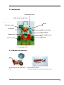
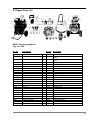
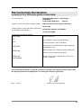
Operating Instructions
for
Pruning Machine
NIKO I
Typ 180 / 250
NIKO GmbH Maschinen- & Fahrzeugbau . Im Mühlgut 1 . D-77815 Bühl-Weitenung
Introduction
Dear customer
We would like to thank you for your confidence in purchasing a NIKO product.
We did our best to deliver you an efficient and reliable product.
We kindly ask you to read the operating instruction as well as to observe all other instructions before starting
the machine. This operating instruction will give you detailed information about starting up the machine and
about the maintenance.
As you know, the warranty does not cover any claims resulting from operating errors or inappropriate use.
In case of ordering spare parts, accessories or submitting complaints, it is absolutely necessary to state the
following data:
Type:
Pruning Equipment NIKO I Typ 180/250
Technical Improvements:
We are always trying to improve our NIKO products. Therefore we reserve the right to implement all
improvements and changes we think to be necessary on our products without further announcement and
without obligation of updating machines that are already sold.
We are glad to answer any further questions you may have and wish you lots of fun with your new NIKO
product.
Best regards!
N I K O
Maschinen- & Fahrzeugbau
Dieter Serr, General Manager
Index
•
Product Description
1.) Appropriate use
2.) Construction
2.1) Available accessories
2.2) Spare parts list
3.) Functional description
4.) Technical data
5.) EG-conformity declaration
•
General Safety Information
1.) Care
2.) Description of the symbols used
•
Transport
1.) Dimensions and weight
•
•
Help with breakdowns
Possible breakdowns and their elimination
•
Maintenance
1.) Cleaning and lubrication
2.) Servicing
3.) Motor servicing
•
Warranty conditions
Product description
1. Conventional usage
The NIKO Pneumatic Pruning Machine is only made for:
-
the use of Pneumatic tools, which are approved and sold by NIKO (Pneumatic Shears, Hook shears,
Hedge cutters, Pruning Saws, Chainsaws and Tree shakers)
The machine is not adequate for any operations as the above mentioned – this is considered as inadequate
use!
1
2. Construction
Wartungseinheit
Maintenance unit
Handstarteinrichtung
Hand
launching adjustion
Benzinhahn/
Starterklappe
Fuel tap / choke
Motor
Oil dipstick
Ölmeßstab
Werkzeug-Anschluß
Tool
connection
Schlauchtrommel
Hose
drum
Kompressor
Compressor
Öleinfüllöffnung
Oil charging hole
Ölauge
Oil
eye
Pressure tank
Druckkessel
Discharge screw
Ablaßschraube
2.1 Available accessories
Spring-driven or hand-rollable Hose
reels
NIKO Pneumatic Shears
and tools (Pruning Saw, Chainsaw, Hook Shear etc.)
2
2.2 Spare Parts List
NIKO I Pruning equipment
Typ 180 / 250
Art. No.
Description
Art.-No.
16001
16002
Motor GX 110
Compressor
16024
16025
16003
Pressure reed
16025a
16004
16005
16006
16007
16008
16008a
16008b
16009
16010
16011
16012
16013
16014
16015
16015a
16016
16017
16018
16019
16020
16021
16022
16023
Frame
Holder grip
Front panell
Cover bonnet
Take out incl. Niko disc
Axial ball bearing
Ball bearing
Adjusting screw
Magnet
Fan-stage disc
V-belt disc
V-belt
Belt tensioner (old extender)
Wheels
Hubcaps
Drain spigot
Distributor
O-Rings
Axes chromed
Barrell incl. Gear rim
Belt incl. Cutterb
Hose eye
Protection valve
16026
16027
16028
16029
16030
16031
16032
16033
16034
16035
16036
16037
16038
16039
16040
16040a
16041
16042
16043
16044
16045
16046
16047
Description
Maintenance unit
Maintenance unit holding, new (Aluminium
holder)
Maintenance unit holding, old (steel sheet
holder)
LCK-Screwing
Hollow screws
Overthrowing nut
Gaskets
Buckling protection feathers
Eyelet
Coupling
Distributor FR 4
Snap hook
Connection
Connection incl. Buckling protection
Connection
Connection incl. Buckling protection
Oil connector
Screws incl. Padding disc
Pressure nut
Screws incl. nut
Screws incl. nut
Drain valve
Babbitt metal liner
Fitting connection
Manometer Q 45
Manometer Q 40
3
3. Functional description
Before starting the pruning machine:
1.) Control the motor oil
2.) Check the compressor oil stand
3.) Check the stand of oil in the maintenance unit
4.) Discharge the water in the waterprecipator of the maintenace unit
5.) Check the stand of fuel
6.) Discharge overpressure from the pressure tank with the drain screw
To start the pruning machine:
1.) Close the choke if the motor is cold
2.) Open the Fuel tap
3.) Pull out the starting control slightly until you note some resistance, then pull through zestfully and pull the
control back
4.) Close the choke again
5.) Attach pneumatic tools
While working with the pruning machine:
1.) Check the stand of oil in regular intervals (approx. each 5 hours)
2.) Discharge water in the waterprecipator of the maintenance unit in regular intervals (approx. each 3
hours)
3.) Discharge water at the drain screw of the pressure tank daily
4.) At machines with automatic return Hose reel always wind up controlled
After working with the pruning machine
1.) Check the motor oil
2.) Check the stand of Compressor oil
3.) Check the stand of oil in the maintenance unit
4.) Discharge the water in the waterprecipator of the maintenance unit
5.) Check the stand of fuel
Discharge overpressure from the pressure tank with the drain screw
Storing of the pruning machine:
- Frost proof
- Warm (makes the starting easier)
- Dry
Operation of the maintenance unit (Filterpressurereducer and Oiler)
1.) Maintenance units consisting of Filterpressureducer and Oiler have the function to clean the
compressed air as equipment of liquid and solid components, to regulate the air-pressure and to aerate
the air with oil covered in the finest smoke screen to lubricate cylinders. If they are used the right way
(corresponding to the operating conditions) they remain at the level of efficiency and advance the
durability.
1.1) Filterpressurereducer (Filter) The compressed air contains condensation water, tube scales,
pieces of rust and similar things that corrode and disturb the function of the pneumatic controlled tools,
pressure cylinders, valves etc. For that reason the cleaning of the compressed air is necessary and gets
caused by the filter. The degree of cleaning depends on the pore width of the Sinter filter. If desired the
Sinter filter can be installed with less pore width.
Maintenance: Discharge condensation water regularly and clean the Sinter filter if it is dirty.
Demounting: Release screws, take of the container, release the nut of the Sinter filter, take out the
Sinter filter. Place the Sinter filter in solvent (for example fuel) pivot well and dry it, then reinstall it. Please
pay attention to a faultless sealing. Cleaning of the plastic containers.
4
1.2) Pressure Reducer: Very Important, please take note of it: The top cover toggle screw has to be
released at the end of the season. The line pressure of a compressed air machine is unsteady and
2
depends on the size of the compressor (10-16Kp/cm ). Pressure reducers reduce this unsteady line
pressure (primary pressure) to the desired working pressure (secondary pressure) and keep it constant.
For Maintenance units Filter pressure reducers with return control are used. Filter pressure reducers with
return control have the advantage, that it is possible to reduce the secondary pressure without discharge
of air but by turning back of the regulation screw. Furthermore the backstrokes, that appear at pneumatic
controls get conducted in the atmosphere by back control which can also be counted as a safety valve,
this procedure protects the Manometer. Pressure setting: Before launching the air line, discharge the
filter pressure reminder by unscrewing the regulating screw. Then turn in the regulating screw in
clockwise direction until the Manometer shows the working pressure desired at the Pressure Reducer.
1.) Fogoiler: The compressed air gets concentrated by the fogoiler with a fine oilfog and effectuates in this
condition a continuous and steady lubrication of pneumatic controlled compressed air tools, cylinders,
2
valves etc. Please Note: Minimum working pressure 0,5 kp/cm . The fogoilers work correspondant to the
working pressure with minimum air consumption. This minimum air consumption was measured with an
oil of 2,8° E (50°C) Proportioning: Regulate the amount of oil (approx. 1 drop per 30 shear strokes)
while working with the machine at the proportioning screw as desired. The amount of drops can be seen
in the glass sight funnel. Filling in of the oil: Remove the fill in screw, fill the container until the fill in
mark (approx. 2/3). Close the fill in screw well. It is possible to refill the oil while working with the
machine, the air supply does not have to be stopped. The cleaning of the plastic containers is only
permitted with water, petroleum or cleaning solvent.
2.) Setting up the amount of oil:
Adjust in clockwise direction „less oil“
In counter clockwise direction „more oil“
ATTENTION MORTAL DANGER !!!
NEVER MANIPULATE AT THE OVERPRESSURE VALVE OR THE FREEWHEEL VALVE !!!
Maintenance and Reparations should only be made from professional shops.
4. Technical Information
-
4 or 5,5 PS Honda-Motor (GX 160 / GX 270) with automatical oil stopping
1-rotor-compressor with 180 or 250 liter air capacity
Working pressure until 16 bar
Automatical Oil warning system
Freewheelvalve ( Automatical disconnection )
Maintenance unit (Air filter, Pressurereminder, Fogoiler)
Connection for 1-2 shears
Measurements and Weights
Height:
Width:
Depth:
Weigth:
92 cm
68 cm
65 cm
52 Kg
5
EG-Conformity Declaration
according to II A of EG machine guidelines (89/392/EWG)
The manufacturer:
NIKO GmbH Maschinen- & Fahrzeugbau
Im Mühlgut 1
D-77815 Bühl-Weitenung
Germany
declares, that the machine described as follows:
NIKO I Pruning machine Type 180 Economy
Machine No.
complies with the safety and health requirements
of the following EG-guidelines:
EG-Machine Guideline 89/392/EWG
Version 93/44/EWG
Harmonized standards applied:
DIN EN 292
Safety of machines:
Teil 1
Basic definitions, general design guidelines
Teil 2
DIN EN 294
DIN EN 349
Technical guidelines and specifications
Safety distances to avoid contact of upper body parts
with dangerous area
Minimum distance to avoid the pinching of body parts
Machine safety, emergency stop device
DIN EN 418
DIN EN 60204
Machine safety; general requirements for electrical
machine equipment
This conformity declaration is voided by constructive changes, affecting both technical data stated
the operating instruction and appropriate use, altering the machine significantly!
Bühl, 11.10.12
Dieter Serr, General Manager
6
General Safety Information
Operator’s care
The NIKO c pruning machine was designed and constructed under consideration of a threat analysis and
after an accurate selection of the maintained norms as well as well as some further technical specifications.
That accords to the state-of-the-art and guarantees a maximum safeness.
That safeness can just be obtained when all necessary measures are considered. It is the liability of the
operator to arrange these measures and to control their execution.
The operator has to make sure, that ...
-
the shear has to be used according to the regulations (see chapter „Product Description“)
the shear will only be operated in a proper and fully functional condition
all necessary protective equipments for the operator are at your disposal and are used as well
the operation instruction is in a legible condition and is available at the location
only adequate qualified and authorized persons work with the machine, repair and maintain it
the employees are always able to answer all the questions concerning job safety and environmental
protection and also get instructed about it regularly
the operator wears a safety glove
all safety information which are applied to the machine are not being removed and that they stay legible
the advices in this manual as well as the general valid safety and accident precaution regulations are
followed
before starting to work with the machine you have to make sure, that you know about all of the equipment
and the operating elements, as well as their function. While working with the machine it is too late!
the clothing of the operating staff should suit closely. Loose worn clothes should be avoided.
-
before starting the machine the close up range is checked (CHILDREN !!!)
-
you do not leave the motor working in closed rooms (POISONING)!
-
while working with fuel you have to be very cautious because there is a high Fire danger!!!
the fuel is never refilled next to unshielded flames or ignitable sparks
no one smokes while refuelling!!!
the motor is stopped before refuelling. Do not refill the fuel in closed rooms.
submerged fuel is removed instantly (Fire danger)
the machine is kept clean to avoid fire danger
before start working with the machine the operating reliability is checked!
the pruning machine is only used by persons that are in a mental and physical acceptable condition,
before and while working with the machine it is not allowed to consume pills or alcohol
the machine is not being used from persons that are underage
the machine is secured against rolling away
the pruning machine is never unattended while the motor is still working
the machine only gets started if all protection devices are installed and are in protection setting
-
-
7
MAINTENANCE
2. Explication of the safety symbols used
In the manual for this machine, the following safety symbols are used. These symbols are there to call the
readers attention to the text of the adjoining security advice.
These symbols point out that there is a risk for the life and health of persons working.
Fire danger!
Risk of suffocation!
No smoking!
Fire danger!
This symbol points out, that there is a danger for the machine,
the material or the environment and marks the information
that help to understand the functions of the machine better.
Transport
To avoid damages at the machine or injuries while the transport it is essential to respect the following items:
- transport workings are only allowed to be made if the security advices are followed
- the machine can only be hoisted or fixed at the holding points which are made therefore
- do not transport the machine horizontal
Help with breakdowns
To avoid engine troubles or life-threatening injuries while fixing breakdowns at the machine, it is necessary to
respect the following items:
- only fix a breakdown if you have the desired qualification
- secure the machine against rolling away and an unintended restart
- assure at all times a safety shut down of a second person
- secure the action area of the flexible parts of the machine
- also read the chapter „General Safety Information“
Tabular overview of possible fault reports and help for fixing of the
breakdowns
Reason
Correction
Machine does not start
•
Motor can only be pulled through badly
•
•
•
•
Machine does not produce any pressure
•
•
•
Engine fuel supply
- open the fuel tap
- fill in the fuel
Check the stand of oil and refill it if necessary
Adjust the ignition switch on 1
Close the choke
Discharge the air at the pressure tank using the
drain screw
Drain plugs are closed (Maintenance unit,
pressure tank)
Check the v-belt
Check the hoses and pipes on breakdowns
8
MAINTENANCE
Maintenance
To avoid engine troubles or injuries during the maintenance of the machine it is essential to respect the
following items:
-
All working steps have to be mandatorily made in the stated order
Secure the maintenance area in a wide range
Switch all units of pressure at zero pressure
Only use the stated operating materials
Only use the spare parts that are mentioned in our spare part lists
Also read the chapter „General Safety Information“
1. Cleaning and lubrication
•
•
•
Clean the filters of the maintenance unit at the end of the season
Clean the air strainer of the compressor after each 50 operating hours
Clean the motor air filter according to the motor guide
2. Maintenance
•
Check the tension of the v-belt
Motor maintenance
• Please respect the guide of the motor manufacturer for this topic
• Do not do any maintenance while the motor is working
• Only refill the fuel if the motor is switched off
• Attend the required quality of oil and fuel and only store them in the containers that are therefore allowed
• Pay Attention while discharging hot oil – Burning danger
• Dispose discharged oil in proper form
• Reinstall the protection devices after the maintenance
9
Warranty
NIKO-products are built using modern manufacturing technologies with a maximum of care, subjected to
numerous quality controls.
This is why NIKO offers a 12 months warranty, if the following conditions are met:
1.) The warranty starts at the day of purchase
2.) The warranty includes material and manufacturing defects. For subsupplier parts (hydraulics, electronics,
engine) we are only responsible to the extend of the warranty of the respective subsupplier. During the
warranty period fabrication and material defects are handled free of charge by replacement or refitting of
parts in question. Others, further claims, such as trade, discount, or damage compensation not
concerning the delivered products are explicitly excluded.
Warranty claims are exclusively handled by authorized repair shops, NIKO-manufacturing
representatives, or the manufacturer.
3.) Excluded from the warranty are damages due to wear, soiling, corrosion, and all faults caused by
inappropriate use and its consequences. Also, unauthorized repairs or changes of original conditions void
the warranty. No recovery of damages is possible if spare parts other than original NIKO-parts are used.
Therefore, please pay special attention to the operating instructions. Direct any questions you may have
to our manufacturing representatives or directly to the manufacturer.
Warranty claims have to be submitted to the manufacturer within 30 days form the date of damage.
Please provide the date of purchase and the machine number and use the warranty form provided.
Warranty repairs can only be carried out by an authorized repair shop, after consulting with NIKO. Please
advise your repair shop accordingly.
Repairs done under warranty do not extend the warranty period!
Faulty transport is not a manufacturing fault, and therefore, is not the responsibility of the manufacturer.
4.) Claims for damages other than on the products itself are excluded. This includes liability for damages
resulting from operating error. Unauthorized modifications to the product can lead to damages and
release the shipper from any responsibility for these damages.
10