1
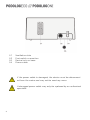
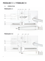
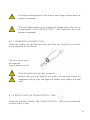
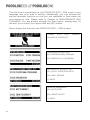
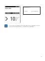
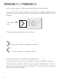
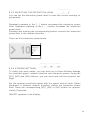
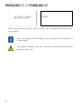
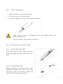
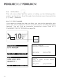
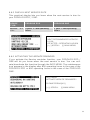
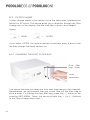
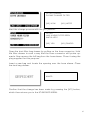
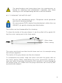
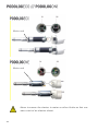
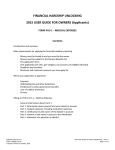
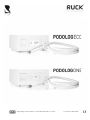
Operating Instructions | Revision 06/2014 | Print
| Item No. 8013301
230 V variant item
no. 11011
115 V variant item
no. 11021
230 V variant item
no. 11012
115 V variant item
no. 11022
These operating instructions apply to the footcare systems
PODOLOG ECO (item no. 11011) and PODOLOG ONE (item no.
11012), referred to in the descriptions that follow as the PODOLOG
ECO / ONE.
2
Dear Customer,
Thank you for choosing a PODOLOG ECO or PODOLOG ONE. This
high-quality product from RUCK will provide optimum support for your
day-to-day work, whether based in a practice or on the move.
Backed by our name and our two-year guarantee, you can be assured
of many years of enjoyable and problem-free operation.
Please take some time to read through these operating instructions
carefully before setting up the system. These constitute part of the device, help you avoid possible operational errors and should be kept in
proximity to the device.
We wish you much success and enjoyment in the very responsible and
challenging work that you undertake.
Kind regards, HELLMUT RUCK GmbH
3
TABLE OF CONTENTS
1.
Device description .................................................7
1.1
1.1.1
1.1.2
1.1.3
Explanation of the characters and icons used ....................... 9
On the device and transport packaging
9
In the operating instructions
9
Display warnings
10
1.2
Scope of delivery ............................................................... 10
1.3
Packaging .......................................................................... 10
1.4
Recycling ........................................................................... 11
2.
Intended usage .................................................... 12
2.1
Operator requirements ....................................................... 12
2.2
Operator and client safety .................................................. 12
3.
Risks and side effects .......................................... 13
3.1
Possible client risks ........................................................... 13
3.1.1 Allergy risks
14
3.1.2 CLIENT injury caused by splinters
14
3.1.3 CLIENT injury caused by heat, output of energy and matter,
heat as a result of friction on the skin or nails
15
3.1.4 Injury caused by hair growth in the treatment area
15
3.1.5 CLIENT injury caused by accidental invasive applications 15
3.1.6 Permanent visual inspection minimises invasive
applications
15
3.2
3.2.1
3.2.2
3.2.3
4
Operator risks .................................................................... 16
Allergy-related risks
16
Operator injury caused by splinters
16
Injury caused by hair, jewellery or clothing coming into
contact with rotary tools
17
4.
Set-up.................................................................17
4.1
5.
Technical safety ................................................................ 17
Operation ............................................................20
5.1
5.1.1
5.1.2
5.1.3
5.1.4
5.1.5
Preparations for operation ................................................. 21
Inserting a rotary tool
23
Switch on the PODOLOG ECO / ONE
23
Switching the holder on
26
Switching the holder off
26
Switching off the PODOLOG ECO / ONE
27
5.2
5.2.1
5.2.2
5.2.3
5.2.4
5.2.5
Settings ............................................................................ 27
Holder motor speed
27
Righthand / lefthand direction of rotation
28
Modifying the rotation direction
28
Selecting the extraction level
29
Storing settings
29
5.3
Tool changing .................................................................... 31
5.4
Ergonomic holder grip ....................................................... 31
5.4.1 Fountain pen grip
31
5.4.2 Overhand grip
31
5.5
5.5.1
5.5.2
5.5.3
6.
6.1
Info menu .......................................................................... 32
Filter change
32
Display next service date
33
Activating the service reminder
33
Maintenance and cleaning .....................................34
Maintenance ...................................................................... 34
6.2
Filter change ..................................................................... 36
6.2.1 Changing the dust filter bag
36
6.2.2 Where can you get replacement dust filter bags?
38
5
6.3
Cleaning the motor unit ...................................................... 38
6.3.1 Cleaning the motor unit
39
6.4
7.
Cleaning and disinfecting the controller .............................. 41
Accessories and spare parts.................................. 42
7.1
Tools ................................................................................. 42
7.2
Dust filter bags .................................................................. 42
7.3
Foot controller ................................................................... 42
8.
8.1
9.
Technical Data .................................................... 43
Environmental conditions ................................................... 44
Guarantee ........................................................... 45
10. Disposal ............................................................. 46
6
1.
DEVICE DESCRIPTION
01
02
03
04
05
Controller
Display
Dust filter bag drawer
Hose connection
Holder
7
01
02
03
04
Ventilation slots
Foot switch connection
Device lock on base
Power cable
If the power cable is damaged, the device must be disconnected from the mains and may not be used any more.
A damaged power cable may only be replaced by an authorised
specialist.
8
1.1
EXPLANATION OF THE CHARACTERS AND ICONS USED
1.1.1 ON THE DEVICE AND TRANSPORT PACKAGING
Device with protection class II
First digit
IP42
0
4
Protection against
contact
Protection against
foreign bodies
No special protection
Against tools, wires
and similar with a
thickness of more
than 1 mm
Granular foreign
bodies with a diameter of more than 1
mm
Second
digit
Protection
against water
0
No special
protection
2
Against water
dripping at an
angle (up to
15° deviation
from the vertical)
Protect against wet and damp
1.1.2 IN THE OPERATING INSTRUCTIONS
Warning! This icon identifies a potential point of danger for people or for the device itself. It must be taken
note of .
This symbol identifies useful advice that offers you
additional information related to the operation of your
PODOLOG ECO / ONE .
9
1.1.3 DISPLAY WARNINGS
"HOLDER BLOCKED!" - If the holder is blocked,
the motor speed and suction turbine are
switched off after about 5 seconds. This warning
disappears after about 10 seconds, after which
the holder speed can be reset.
"EXTRACTION OVERHEATING" - If the permissible air temperature in the suction turbine housing
is exceeded, the suction turbine and holder are
switched off. Once the temperature has fallen by
around 10 - 15 °C, this warning disappears and
the holder speed can be reset.
1.2
SCOPE OF DELIVERY
Please take some time to read through these operating instructions
carefully before using the PODOLOG ECO / ONE for the first time.
Please check that the delivery is complete.
The following items make up the scope of the delivery:
PODOLOG ECO / ONE controller
Holder with hose and drawer
1 Dust filter bag
1 Set of operating instructions
1 Device logbook
1 Cleaning tool
1 Holder base
1.3
PACKAGING
The packaging has been designed to protect the device while in transit.
The materials used have been selected with due regard to environmental issues and with recycling in mind.
10
Please keep the packaging (box, plastic bag, foam) to use for returning
the device in case of any maintenance work.
1.4
RECYCLING
Old equipment must be disposed of as electronic waste and should not
be treated as domestic waste. Full dust bags can be disposed of with
general rubbish.
Please make sure you follow any local guidelines in this respect.
Special country-specific requirements should also be taken into account.
11
2.
INTENDED USAGE
The PODOLOG ECO and PODOLOG ONE footcare systems operate rotating tools such as nail file drills and grinders for the removal of hard
skin, calluses, nails, etc. from feet and hands. The device is intended
for use in the following fields of activity: Footcare, nail design, cosmetics, wellness and related professions.
Any other usage is undertaken at your own risk and could be dangerous. Improper usage of the device can lead to personal and material
damage.
The manufacturer cannot be held responsible for any damage caused
by improper or incorrect usage of the equipment.
All rights under the terms of the guarantee are rendered null and void
by any improper usage or if the device is opened!
No changes or modifications may be made to the device or
its accessories. Should a repair be required, the necessary
safety checks must be repeated.
2.1
OPERATOR REQUIREMENTS
The footcare system should only be used by pedicurists, cosmeticians,
nail designers or other related professionals, who are aware of how the
system operates and have received the necessary training.
2.2
12
OPERATOR AND CLIENT SAFETY
−
Only use high-quality rotary tools in accordance with DIN EN ISO
1797-1, which have a standardised shaft measurement of 2.35 mm
∅, cylindrical, Type 2.
−
Please take note of their instructions for use and the maximum
speeds in accordance with the manufacturer’s specifications for rotary tools as well as information concerning cleaning, disinfecting
and sterilisation. You will find additional information in the current
catalogue from HELLMUT RUCK GMBH, in the section "Rotary instruments".
−
Operators should not come into contact with the foot controller
connection and the client at the same time.
−
Protective low voltage must be maintained.
−
Operators must wear eye, mouth and nose protectors and gloves
while using the equipment.
−
During treatment, the operator must ensure that hair or loose items
such as towels, tamponades, etc. cannot get onto the area of the
rotary tools.
−
The tools must be disinfected, cleaned and if necessary sterilised
after each usage or change of client, in order to avoid the possible
transfer of germs from one client to another.
You will find suitable products in our catalogue under the section
"Hygiene".
−
Any other surfaces of the equipment, including the holder that may
have become contaminated, must be disinfected and cleaned. Under no circumstances should any fluids get into the holder as this
may cause damage to the device.
3.
RISKS AND SIDE EFFECTS
The likelihood of any person-related risk can be restricted to a very few
points by the professional and proper usage of the PODOLOG ECO /
ONE.
3.1
POSSIBLE CLIENT RISKS
The extraction of potentially pathogenic dust significantly reduces the
risks caused by transferable germs (micro-organisms).
The risk to clients through inhalation is reduced to a minimum and the
treatment of clients with low levels of immunity can be responsibly undertaken. Nevertheless, the practitioner should still always wear mouth
and nose protectors as well as safety gloves while carrying out the
treatment.
13
If any germ-intensive work has been carried out, disinfected
and sterilised tools must be used during the next work process, to treat any unaffected areas of skin or nail.
3.1.1 ALLERGY RISKS
In the case of clients with intolerance to components made of medicinal steel, there exists a possibility, albeit a small one, of an allergic
reaction.
As a rule, the length of the treatment with the PODOLOG ECO / ONE is
quite short so the corresponding contact time to potential allergy sufferers is less than 30 minutes.
For this reason, so-called Type IV allergies according to the Coombs
test (previously known as: contact allergy) that can trigger an allergic
reaction through sensitised T-lymphocytes simply through contact with
the skin, can, as a rule, be excluded.
When carried out properly, treatment with a PODOLOG ECO / ONE is
non-invasive. The extraction reduces both the spreading of dust to
neighbouring wound areas and the risk of inhalation of skin cells that
have been drilled or ground off.
A Type I allergy according to the Coombs test (previously known as:
immediate allergy) is less likely but still theoretically possible.
3.1.2 CLIENT INJURY CAUSED BY SPLINTERS
During your work, there can be a high-velocity dispersal of particles
such as nail or glue fragments or parts of the nail file drill, e.g. in the
case of diamond file drills.
Any open and non-treated wound that the client may have in the immediate area of the work should be covered with a sterile dressing.
In such cases, the operator must wear safety glasses (see
Chapter 3.2, Operator risks).
14
3.1.3 CLIENT INJURY CAUSED BY HEAT, OUTPUT OF ENERGY AND
MATTER, HEAT AS A RESULT OF FRICTION ON THE SKIN OR
NAILS
Heat development through friction on the skin is a problem, particularly
when working at higher rev. counts with large-surface nail file drills or
tools.
In cases such as these, the working and contact surfaces should not be
too small. You shouldn't do deep, point-focused work but you should
make wider, sideways cutting movements across the skin. You should
interrupt the contact with skin or nails from time to time to allow the
working areas to cool down.
3.1.4 INJURY CAUSED BY HAIR GROWTH IN THE TREATMENT AREA
It can happen, for example when working on toes or insteps, that thicker and longer hairs grow in the treatment area. This is particularly the
case with male clients.
In order to avoid the risk of these hairs getting entangled in the tool
and being painfully pulled out, they should be cut off as a prophylactic
measure beforehand.
3.1.5 CLIENT INJURY CAUSED BY ACCIDENTAL INVASIVE
APPLICATIONS
There is always the risk of accidental invasive applications when using
rotary tools.
Inconsistencies in the tissues, changes in the depth of skin cornification, sudden movement by the client or lack of concentration on the
part of the operator can all lead to this.
3.1.6 PERMANENT VISUAL INSPECTION MINIMISES INVASIVE
APPLICATIONS
With fine work there should be permanent visual inspection and with atrisk clients, e.g. clients being treated with a coumarin derivative, you
should only work with illuminated magnification.
Invasive working methods should be avoided at all times!
15
The efficient extraction of the PODOLOG ECO / ONE greatly improves
visibility and reduces the risk of accidental deeper injuries.
3.2
OPERATOR RISKS
The extraction of potentially pathogenic dust significantly reduces the
risks caused by transferable germs (micro-organisms).
Risks to the operator through inhalation are kept to a minimum.
For reasons of hygiene we recommend the wearing of
face/mouth protection and gloves.
3.2.1 ALLERGY-RELATED RISKS
If there is a risk of a contact allergy on the surface of the holder or the
nail file drill / tool, the operator should wear gloves. This is recommended for the majority of treatments for hygienic reasons.
3.2.2 OPERATOR INJURY CAUSED BY SPLINTERS
During your work, there can be a high-velocity dispersal of particles
such as nail or glue fragments or parts of the nail file drill, e.g. in the
case of diamond file drills.
This occurs in the immediate area of the operator's eyes (eye contact)
and face and there is a risk of injury.
In such cases, the operator must wear safety glasses!
Safety glasses with sidepieces protect the operator's eyes
against injury and infection. They should be disinfected after
each treatment session.
16
3.2.3 INJURY CAUSED BY HAIR, JEWELLERY OR CLOTHING COMING
INTO CONTACT WITH ROTARY TOOLS
For reasons of working safety, it is vital that long hair is tied back closely to the head or covered with a cap or hat.
For reasons of hygiene, the wearing of jewellery and watches should be
avoided. Working clothes should be selected so that no fringing or
loose material can get caught up in the tool.
4.
SET-UP
4.1
TECHNICAL SAFETY
−
Before using the device for the first time, you should ensure that
mains power characteristics match the values quoted on the rating
plate.
−
Make sure the controller is located on a flat, stable surface.
−
The ventilation slots in the device must be kept uncovered at all
times.
−
Avoid damaging the mains cable through squashing, bending or
rubbing against sharp edges.
−
Don't introduce any fluids into the unit.
−
Protect the device from all types of moisture that could find its way
inside the housing. There is a danger of electrical shock if there is
dampness in the device!
−
Switch the device off before maintenance and cleaning and unplug
it from the mains power.
−
Never immerse the device in water or other fluids.
−
Remove the plug from the mains immediately, if the device is damaged or if it starts to function incorrectly.
−
Repairs should only be carried out by qualified repair technicians.
−
If the device is opened, all rights under the terms of the guarantee
are void!
−
All tools used must comply with the DIN EN ISO 1797-1 in order to
guarantee safe operation. Please see also Chapter 2.2, Operator
and client safety, Page 12.
17
−
Do not store the PODOLOG ECO / ONE directly next to or with other devices. Should this be necessary, please make sure that all
intended functions of the PODOLOG ECO / ONE work properly.
The use of other equipment than that prescribed
may result in increased emissions or reduced immunity to interference.
Risk of strangulation from holder hose and power
cable. Keep children away from the device.
Risk of swallowing in the case of required accessories (small parts), e.g. nail file drills. Keep
children away from the device.
Use the supplied packaging to protect the device
against mechanical damage and damp when
transporting it between deployments.
When using the device in domestic premises, there
can be a risk resulting from power cables that have
been damaged by animals, for example.
Please check the mains power connection regularly for signs of damage and if any are found,
disconnect the device from the mains.
When using the device in domestic premises, there
can be a risk that the device may be tampered with
by children.
Keep children away from the device.
Protect the device against pest infestation through
regular checks and cleaning.
18
The instructions regarding operation and transport
of the device must be adhered to.
Please ensure that you have easy access to the
mains plug at all times so that the device can be
unplugged from the mains without difficulty. The
power plug represents the separator to the mains
power supply.
19
5.
20
OPERATION
01
Standby button
Press this button to activate/deactivate the
standby mode
02
Extraction power
setting
Increase [+] to decrease [-] the extraction
power. The power level is shown in the display.
03
Info menu [ i ]
Through this menu, you can for example, activate the holder cleaning process or check
when the next filter change or service is due.
Press and hold the button for 5 seconds to
change base settings, e.g. language.
04
Buttons for storing
user settings
Three different combinations of rotational
speed, rotation direction and extraction power
can be stored. The memory is shown in the
display (04.1). [M1] [M2] are needed for the
filter change.
05
Righthand
lefthand
06
Speed controller
This is used to set the rotational speed in
steps of 1000 rpm. The current speed is
shown in the display (06.1). If the speed controller is removed, all buttons are blocked.
07
Filter bag change
The icon appears as a reminder that a filter
bag change is due.
08
Foot switch
The icon appears if an optional foot switch is
connected.
09
Service display
The icon appears as a reminder that a service
is due.
10
On/off switch
Switches the device on/off for treatment
5.1
/ Sets the rotational direction of the tool.
PREPARATIONS FOR OPERATION
−
Open the dust filter bag drawer by pulling on the hose connector.
−
Please check if the supplied filter bag has been inserted. If this is
not the case, connect the bag to the sleeve at the end of the tool
hose. Please refer to page 36.
21
−
Close the drawer by sliding it in.
−
Switch the device on using the standby button.
= Standby button on/off
22
You should always work with a dust filter bag in place and securely connected.
The filter bag drawer must always be closed when the unit is
in operation. The PODOLOG ECO / ONE switches off if the
drawer is opened.
5.1.1 INSERTING A ROTARY TOOL
Insert the rotary tool (grinder/nail file drill) that you need for your work
in the opening of the holder.
The tool only has to
be inserted
(quick-action chuck).
The tool shaft must be fully inserted!
Ensure that the tool shaft is not bent, as this may cause an
imbalance which may damage the holder and impair the tool
hold.
5.1.2 SWITCH ON THE PODOLOG ECO / ONE
Press the standby button. The PODOLOG ECO / ONE is now switched
on and ready to use.
23
The first time it is switched on, the PODOLOG ECO / ONE is set to your
language and your area of activity. Additionally, you can activate the
service reminder function so that you are reminded in time when the
next service is due. Please refer to Chapter 6, MAINTENANCE AND
CLEANING. You are guided through the Start menu, step-by-step. At
the end, you confirm your inputs with the [M1] button.
Menu display the first time the PODOLOG ECO / ONE is used:
THANK
YOU
FOR
CHOSEN A PODOLOG
HAVING
LANGUAGE SELECTION
[M1] GERMAN [M3] SPANISH
[M2] ENGLISH [<>] RUSSIAN
MY FIELD OF ACTIVITY IS:
[M1] FOOT CARE/PODIATRY
[M2] NAIL DESIGN
[-] BACK
SERVICE REMINDER
[M1] ACTIVATE?
[M2] DEACTIVATE?
[-] BACK
24
THANK YOU!
[-] BACK
[M1] FINISHED
If you want to modify any of the Start menu settings in the future, press and hold the [ i ] button for 5 seconds.
25
5.1.3 SWITCHING THE HOLDER ON
Set the required rotational speed using the speed control knob. The
displayed number x 1000 indicates the rpm value. Grip the holder and
operate the switch at the rear end of the holder.
Switch
Switch
The motor runs at the set speed and you can start your work.
The speed setting may not exceed the permitted maximum
speed of your tool.
5.1.4 SWITCHING THE HOLDER OFF
While the motor is running, operate the switch at the rear end of the
holder.
The motor is switched off and you can pause your work.
26
5.1.5 SWITCHING OFF THE PODOLOG ECO / ONE
Press the standby button. The PODOLOG ECO / ONE is now switched
off and goes into stand-by mode.
Please ensure that you have easy access to the
mains plug at all times so that the device can be
unplugged from the mains without difficulty. The
power plug represents the separator to the mains
power supply.
5.2
SETTINGS
5.2.1 HOLDER MOTOR SPEED
The rotational speed that corresponds to the tool being used is set using the rotational speed knob.
Clockwise rotation
Counterclockwise rotation
– Speed is increased
– Speed is decreased
Max. speed:
25 000 rpm
Min. speed:
4000 rpm
For large-surface drilling / grinding, the optimum rotation speed is in
the range from: 8000 – 12 000 rpm.
The speed setting may not exceed the permitted maximum
speed of your tool.
You will find the maximum permitted rotational speeds for all
nail file drills and grinders in the "Rotary Instruments" chapter
of the HELLMUT RUCK GMBH Catalogue.
27
5.2.2 RIGHTHAND / LEFTHAND DIRECTION OF ROTATION
You can set your tool to righthand or lefthand rotation depending on
which tool you are using and on whether you are right-handed or lefthanded.
Righthand rotation
The arrow shows the direction of rotation.
Arrow to the right – Righthand rotation
Arrow to the left – Lefthand rotation
5.2.3 MODIFYING THE ROTATION DIRECTION
The rotation direction can be modified while the machine is running.
Press the arrow button. The set motor speed automatically returns to
zero and the rotation direction is changed. The motor starts up again at
the previous speed setting.
28
5.2.4 SELECTING THE EXTRACTION LEVEL
You can set the extraction power level to meet the current working requirements.
Repeated pressing of the [ - ] button decreases the extraction power
level. Repeated pressing of the [ + ] button increases the extraction
power level.
Pressing and holding the corresponding button controls the extraction
power level in the desired direction.
There are five extraction power levels.
5.2.5 STORING SETTINGS
To make your work easier, you can store up to three different settings
for rotational speed, rotation direction and extraction power. Using the
[M1], [M2] and [M3] buttons, you can store and call the required settings.
Set the required rotational speed with the speed control knob. Select
righthand or lefthand rotation direction. Select the extraction power
level. Press the corresponding [M1], [M2] or [M3] button for approximately 2 seconds.
"SAVED" appears in the display.
29
SAVED
With a short press on [M1], [M2] or [M3], the corresponding stored value is called.
You can change the settings at any time while the machine is
in operation.
The speed setting may not exceed the permitted maximum
speed of your tool.
30
5.3
−
−
−
TOOL CHANGING
Switch off the motor at the holder.
Pull the tool out of the holder.
Insert a different tool into the holder opening.
Tools should only be changed when the holder motor has
been switched off.
The tool shaft must be fully inserted!
5.4
ERGONOMIC HOLDER GRIP
5.4.1 FOUNTAIN PEN GRIP
Fine work can be done ergonomically
and accurately using the fountain pen
grip.
5.4.2 OVERHAND GRIP
When carrying out surface work, gripping the holder from above and supporting it with the thumb makes for
accurate and relaxed working.
31
5.5
INFO MENU
The Info menu offers you the option of calling up the following information and functions. Scroll through the individual menu items with the
[ + ] and [ - ] buttons.
5.5.1 FILTER CHANGE
If you want to change the fine dust filter, you can do this using the Info
menu and inform the device at the same time that a new filter has been
inserted. You will find an extensive description under Point 6.2.1
CHANGING THE FILTER BAG on page 36.
FILTER CHANGE
PLEASE CHANGE FILTER
[M1] NOW
FILTER
HAS A NEW
INSTALLED?
[M1] YES
32
[M2] LATER
FILTER
BEEN
[M2] CANCEL
5.5.2 DISPLAY NEXT SERVICE DATE
This practical display lets you know when the next service is due for
your PODOLOG ECO / ONE:
DEVICE
TYPE:
Service
after:
due
PODOLOG ECO
PODOLOG ONE
2 years or 900 operating
hours
1 year or 500 operating
hours
INFO MENU
NEXT RECOMMENDED SERVICE:
01/20..
OR AFTER …OPERATING HOURS
[+/-] SCROLL [i] MAIN MENU
.
5.5.3 ACTIVATING THE SERVICE REMINDER
If you activate the Service reminder function, your PODOLOG ECO /
ONE will let you know when the next service is due. You can activate/deactivate this function through the INFO MENU. The maintenance
icon appears in the display after 900 operating hours in the case of the
PODOLOG ECO or 500 operating hours in the case of the PODOLOG
ONE.
INFO MENU
ACTIVATE SERVICE REMINDER?
PLEASE PRESS [M1]
[+/-] SCROLL
[i] MAIN MENU
33
INFO MENU
DEACTIVATE SERVICE
REMINDER?
PLEASE PRESS [M1]
[+/-] SCROLL
6.
MAINTENANCE AND CLEANING
6.1
MAINTENANCE
[i] MAIN MENU
To a great extent, the PODOLOG ECO / ONE is maintenance-free. The
most important aspect of maintenance is the timely changing of the filter. It guarantees a correct suction function.
You should clean the outside of the device and disinfect it if
required after each treatment and remove dust particles from
the holder at least once a day.
You will find suitable products in our catalogue under the section "Cleaning and Disinfection". We recommend using RUCK
alcohol-free disinfectant cloths to clean and disinfect the motor unit (item no. 2942801).
Switch the device off before cleaning and unplug it from the
mains power!
Return the device for regular maintenance:
34
HELLMUT RUCK GmbH
Daimlerstraße 23
75305 Neuenbürg
Germany
Tel. +49 (0) 7082 944 20
Fax +49 (0) 7082 944 22 22
[email protected]
35
6.2
FILTER CHANGE
A filter change needs to be carried out at the latest after operating the
holder for 30 hours. The device gives you a reminder through the filter
change icon in the display, that the dust filter is due to be changed.
Select:
=
NOW
=
LATER
If you select LATER, the device displays a reminder every 5 hours until
the filter change has been carried out.
6.2.1 CHANGING THE DUST FILTER BAG
Dust filter
bag drawer
Hose
connector
The device reminds you when the dust filter bag needs to be changed.
Nevertheless, we recommend that you check how full the filter bag is
once a week. To change the dust filter bag, press the [ i ] button to access the INFO MENU. There, you can scroll with the [ + ] or [ - ] buttons
to the Filter change menu item:
36
FILTER CHANGE
PLEASE CHANGE FILTER
[M1] NOW
[M2] LATER
Start the change process with the [M1] button:
FILTER
HAS A NEW FILTER BEEN
INSTALLED?
[M1] YES
[M2] CANCEL
Open the dust filter bag drawer by pulling on the hose connector. Hold
the filter drawer in such a way that the hose connector still points upwards. Now remove the full bag from the hose sleeve. Close it using the
plug supplied for this purpose.
Insert a new bag and locate the opening over the hose sleeve. Close
the dust bag drawer.
SAVED
Confirm that the change has been made by pressing the [M1] button,
which then returns you to the STANDARD MENU.
37
The dust filter bag should not be emptied and reused.
Should you use the device for the treatment of artificial nails
(nail design, nail prosthesis) please take into consideration
that the time between filter changes shifts due to the high degree of erosion. A weekly check of the level is necessary to
ensure smooth operation. When treating artificial nails please
do not forget to protect your eyes, mouth and nose by using a
face-mask and goggles!
Once a week, you should check that the dust filter bag drawer
is correctly seated and at the same time, you should also
check the filling level of the bag. The procedure that you need
to follow is detailed above. If necessary, you should replace
the dust filter bag.
6.2.2 WHERE CAN YOU GET REPLACEMENT DUST FILTER BAGS?
New dust filter bags can be ordered from HELLMUT RUCK GmbH under the item number 110501.
Please ensure that you only use original dust filter bags from
the manufacturer.
6.3
CLEANING THE MOTOR UNIT
The holder should always be cleaned inside and the sleeve should be
disinfected after each use. To do this, the holder can be disassembled.
38
The specifications and instructions from the manufacturer referring to cleaning and disinfectant materials and those
referring to the corresponding devices must be followed.
6.3.1 CLEANING THE MOTOR UNIT
Do not use disinfecting sprays. Dampness could penetrate
and lead to bearing damage.
We recommend RUCK alcohol-free disinfectant cloths (item no
2942801) for gentle cleaning and disinfection.
The holder can be disassembled for cleaning.
To clean the inside of the grip sleeve, it can be pulled off by gently tilting the motor casing and motor base apart.
Motor base
Motor casing
This releases the connection with the motor.
The motor and chuck can then be slid down and out, for example using
the drill pin supplied.
The inside of the grip sleeve can then be cleaned.
To reassemble the holder, align the motor unit with the guide rails on
the motor casing. When assembling the motor connection, please attach and slide in the plug connectors (02) carefully to avoid damaging
the contact pins (01). Make sure the plug connectors are correctly and
symmetrically aligned.
39
Motor unit
Motor unit
Never immerse the device in water or other fluids as this creates a risk of an electric shock.
40
Do not use disinfecting sprays. Dampness could penetrate
and lead to damage to the electronics.
We recommend RUCK alcohol-free disinfectant cloths (item no
2942801) for gentle cleaning and disinfection.
6.4
CLEANING AND DISINFECTING THE CONTROLLER
The controller can only be cleaned externally using a special plastics
cleaner (e.g. RUCK plastics cleaner, item no. 10335) and a surface disinfecting agent.
Never immerse the device in water or other fluids as this creates a risk of an electric shock.
Do not use disinfecting sprays. Dampness could penetrate
and lead to damage to the electronics.
We recommend RUCK alcohol-free disinfectant cloths (item no
2942801) for gentle cleaning and disinfection.
41
7.
ACCESSORIES AND SPARE PARTS
Please note! The accessories listed here are only to be used
with the PODOLOG ECO / ONE .
Using them with other medical-electrical devices can lead to
increased emissions or reduced immunity to interference for
the device in question.
7.1
TOOLS
You can use all rotary instruments (nail file drill, grinder, polisher, etc)
in accordance with DIN EN ISO 1797-1 with normed, 2.35mm ∅ shafts.
You will find a wide range in our catalogue.
7.2
DUST FILTER BAGS
You should only use original dust filter bags from the manufacturer
(item no. 110501, pack of 3).
7.3
FOOT CONTROLLER
Using this foot controller, the speed can be regulated smoothly and sensitively.
The setting made with the rotary knob serves as the upper limit setting. The foot
control options are limited to the maximum speed setting. The motor stops automatically when you release the foot controller. (Item no. 11045).
42
8.
TECHNICAL DATA
PODOLOG ECO
230 V version
115 V version
Controller dimensions
(W/D/H) in mm
250/235/120
250/235/120
Weight in g
approx. 2800
approx. 2800
Holder dimensions
Length in mm
127
127
Weight in g
approx. 110
approx. 110
Voltage
Controller
230 V, 50 Hz AC voltage
115 V, 60 Hz AC voltage
Power consumption
max. 200 VA
max. 200 VA
Micromotor voltage
24 V
24 V
Constant load
40 W
40 W
Idling speed (rpm)
25 000
25 000
Volume flow at max.
power*
approx. 190 I/min.
approx. 190 I/min.
Fuse
Service due after:
T 1.25 A
2 years or 900 operating hours
T 2.5 A
2 years or 900 operating hours
* The volume flow (l/min.) is measured at the holder's air inlet with a calibrated measuring device.
43
PODOLOG ONE
230 V version
115 V version
Controller dimensions
(W/D/H) in mm
250/235/120
250/235/120
Weight in g
approx. 3300
approx. 3300
Holder dimensions
Length in mm
122
122
Weight in g
approx. 110
approx. 110
Voltage
Controller
230 V, 50 Hz AC voltage
115 V, 60 Hz AC voltage
Power consumption
max. 350 VA
max. 350 VA
Micromotor voltage
24 V
24 V
Constant load
40 W
40 W
Idling speed (rpm)
25 000
25 000
Volume flow at max.
power*
approx. 155 I/min.
approx. 155 I/min.
Fuse
Service due after:
T 2.5 A
1 year or 500 operating hours
T5A
1 year or 500 operating hours
* The volume flow (l/min.) is measured at the holder's air inlet with a calibrated measuring device.
We are not aware of any electro-magnetic interactions between the
PODOLOG ECO / ONE and any other equipment.
8.1
ENVIRONMENTAL CONDITIONS
AMBIENT TEMPERATURE
44
in operation
+10°C to +40°C
in transit and storage
-25 °C (without monitoring of relative
air humidity) up to +70 °C (at relative
air humidity of up to 90 %, without
condensation)
Air humidity
15 % to 90 % (without condensation)
Air pressure
700 hPa (≈ 3000 metres above sea
level)
- 1060 hPa
9.
GUARANTEE
HELLMUT RUCK GmbH (RUCK) gives a two year guarantee on the
PODOLOG ECO / ONE. Normal wear and tear, in particular to bearings,
plug-connections, suction hoses and clamps, is excluded.
The guarantee runs from the date of purchase when the product was
first bought. The date of purchase has to be confirmed by the sales receipt. A claim can only be made in combination with the device
logbook. Within the scope of the guarantee, RUCK will repair faulty
equipment free of charge within Germany or, at RUCK's discretion, will
replace it.
A precondition is the carriage-free return of the faulty device, together
with the specified documentation. The local agent is responsible for
claims made outside of Germany. In case of doubt, please check with
RUCK before returning the device.
The guarantee becomes null and void if we find that the problem was
caused by improper or incorrect installation or usage, by nonobservance of the operating instructions, by external intervention or as
a result of a non-authorised repair or modification.
The guarantee is limited to the repair or exchange of the device. Any
further liability, in particular loss of revenue or earnings is excluded. If it
transpires that it is a problem that is not covered by the terms of the
guarantee or that the period of the guarantee has elapsed, any costs for
inspection and repair are to be borne by the customer.
We reserve the right to make changes to and deviations from the technical design.
45
10.
DISPOSAL
ENVIRONMENTAL HAZARD!
Incorrect disposal endangers our environment.
>>>
Please use available return and collection systems for
disposing of the PODOLOG ECO / ONE at the end of its
life-cycle!
Address
HELLMUT RUCK GmbH
Daimlerstraße 23
75305 Neuenbürg
Germany
46
Tel. +49 (0) 7082 944 20
Fax +49 (0) 7082 944 22 22
[email protected]
47