1
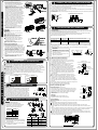
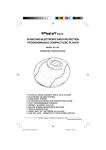
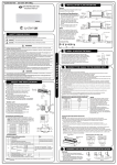
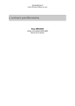
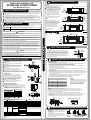
INSTALLATION PLATE MOUNTING
INSTALLATION MANUAL FOR
NOTE:
ROOM AIR CONDITIONER
The mounting wall is strong an d solid enough
to preven t it fro m th e vibr ation .
(Split Wall-Mounted Type)
150mm or more to ceiling 110
180
Installation P late Mounting
Please read this installation manual carefully before operating the unit to ensure correct installation.
If the power cord is damaged, replacement work shall be performed by authorised personnel only.
Installation must be performed in accordance with the requirement of NEC and CEC by authorized
personnel only.
Contact an authorized service technician for repair, maintenance and installation of this unit.
This appliance is not intended for use by persons(including children) with reduced physical, sensory
or mental capabilities, or lack of experience and knowledge, unless they have been given supervision
or instruction concerning use of the appliance by persons responsible for their safety.
Children should be supervised to ensure that they do not play with the appliance.
All the pictures in the instructions are for explanation purposes only. The actual shape should prevail.
The design and specifications are subject to change without prior notice for product improvement.
Consult with the sales agency or manufacturer for details.
NOTE:
Mount the Insta llatio n Plate and drill
holes in the wall according to the wall
structure and corresponding mounting
points on the installa tion plate. The
installation plate providedwith the
machine d iffer from appliance
to appliance.(Dimensions are in
" mm" unless otherwise stated)
SAFETY PRECAUTIONS
Ple ase read these safety precautions carefully before installation
Be sure to fo llow a ll the preca ution s below, they are all important for en surin g safety.
WARN ING
This s ymbol indicates the possibility of death or serio us injury.
CAUTION
This s ymbol indicates the possibility of injury o r damage to pr operty.
120mm or
more to wall
1. Fit the installation plate horizontally on
structural parts of the wall withspaces
Left rear side
around the in stallation plate .
refrig erant
2. If the wall is made of brick, concrete
pipe ho le φ65
or the like, drill five or eight 5mm
diamete r holes in the w all. Insert
clip anchor for appropr iate mounting
screws.
3. Fit the installation plate on the wa ll
120mm or
with five or e ight type A screws.
more to wall
INSTALLATION PRECAUTIONS
Cor re ct or ie nt a tio n
of In st al la tio n Plate
Indoor unit outline
120mm or
more to wall
Right rear side
refrigerant
pipe hole φ65
750
Model A
Indoor unit outline
150mm or more to ceilin g 110
140
120mm or
more to wall
Left rear side
refrigerant
pipe hole φ65
Right rear side
refrigerant
pipe hole φ65
835
Model B
Indoor unit outline
150mm or more to ceiling
12 0mmo r
more to w all
Left rear side
refrigerant
pipe hole φ65
120mm or
more to wall
260
990
135
Right rear side
refrigerant pipe
hole φ65
Model C
WAR NIN G
1) Install according to this installation instructions strictly. If installation is defective, it will cause water
leakage, electrical shock,or fire.
2) Use the included accessories parts and specified parts for installation. otherwise, it will cause the set
to fall, water leakage, electrical shock fire.
3) Install at a strong and firm location which is able to withstand the set s weight. If the strength is not
enough or installation is not properly done, the set will drop and cause injury.
4) For electrical work, follow the local national wiring standard, regulation and this installation instructions.
An independent circuit and single outlet must be used. If electrical circuit capacity is not enough or
defect found in electrical work, it will cause electrical shock fire.
5) Use the specified cable and connect tightly and clam p the cable so that no external force will be acted
on the terminal. If connection or fixing is not perfect, it will cause heat-up or fire at the connection.
6) Wiring routing must be properly arranged so that control board cover is fixed properly. If control board
cover is not fixed perfectly, it will overheat at connection point of terminal, fire or electrical shock.
7) When carrying out piping connection, take care not to let air substances other than the specified
refrigerant go into refrigeration cycle. Otherwise, it will cause lower capacity, abnormal high pressure
in the refrigeration cycle, explosion and injury.
8) Do not m odify the length of the power supply cord or use of extension cord, and do not share the
single outlet with other electrical appliances. Otherwise, it will cause fire or electrical shock.
CAU TI ON
1) This equipment must be grounded and installed with ground leakage current breaker. It may cause
electrical shock if grounding is not perfect.
2) Do not install the unit at place where leakage of flammable gas may occur. In case gas leaks and
accumulates at surrounding of the unit, it may cause fire.
3) Carry out drainage piping as mentioned in installation instructions. If drainage is not perfect, water
may enter the room and damage the furniture.
SELECT TH E BEST LOCATION
Indoor unit
There should not be any heat source or stream
ne ar th e un it.
There should not be any obstacles blocking the
air circ ulation.
A place whe re air circ ulation in the ro om is goo d.
A place whe re dr ainage can be easily done.
A place whe re no ise preve ntion is taken into
co nsideratio n.
Do not insta ll the unit near the d oor w ay.
Ensure the spaces indicated by arrows fro m th e
wall,ce iling,fence or other obstacles.
There should not be any direct sunlight. If unav oida ble,
su nlight prevention should be taken into consid eration.
Outdoor unit
If an awning is built over the unit to pr event
direct sunsight or rain,be careful that heat
ra diatio n from the con dense r is n ot ob structed.
There should not be any animal or pla nt wh ich
co uld be affected by h ot air disch arge d.
Keep the spaces indic ated by ar row from wall
ce iling , fence or o ther obstacles.
Do not place any obstacles which may cause
a short circuit of the discha rged air.
B( mm )
27 6
78 0x540 x2 50
54 9
27 6
76 0x590 x2 85
84 5x700 x3 20
53 0
56 0
29 0
33 5
90 0x 860 x3 15
590
33 3
Left rear side
refrigerant
pipe hole φ65
1
2
3
4
5
6
7
8
9
10
Ins tallation Plate
Clip Anchor
Right rear side
refrigerant pipe
hole φ65
1186
Model D
I
N
D
O
O
R
U
N
I
T
DRILL A HOLE IN THE WALL
1. Deter mine hole positions according to le ft and righ t
side of the insta llatio n pla te. Th e hole cen ter is obtained
by measuring the distance as shown in the dia gram above.
2. Dirll the piping p late hole with φ 65mm hole-core dr ill.
3. Drill the piping h ole a t either the right or th e left and the
hole should be slightly sla nted to the outdoor side.
4. Always take ste ps to prote ct the pipe when drilling metal
grid,metal plate or the like .
CONNECT THE CABLE TO THE IN DOOR UNIT
E lectrical wor k
Electric safety reg ulatio ns for the initial Insta llatio n
1. If ther e is serious safety problem about the power supply, the te chnicians should ref use to insta ll
the air conditioner and explain to the client until the proble m is solved.
2. Power voltage should be in the r ange of 90 %~110%o f rate d voltage.
3. The surge prote ctor and main power switch with a 1.5 times ca pacity of Max. Current of th e
u nit s hould be installe d in p owe r circuit.
4. Ensure the air c onditioner is grounde d well.
5. Accor ding to the attac hed Electrical C onnection Diag ram located on the panel of the outdoor unit
to connect the wire.
6. All wiring must comply with loca l and natio nal electrical codes and be installed by qualified and
skilled electricians.
7. An all-pole disconnec tion devic e which ha s at le ast 3mm separation distance in all pole a nd a residual
current device(R CD) with the rating o f not exce eding 30mA shall be incorporated in the fix ed wiring
a ccor ding to the natio nal rule.
8. An individu al branch circuit and single receptacle used on ly for this a ir conditio ner must b e
availa ble. See th e following table for suggested wire sizes and fuse specifications:
AW G Wi re S ize
10
18
13
16
18
14
25
12
30
10
NOTE:
The cable size and t he curren t of th e fus e
or sw itch are d eterm ined by th e ma ximu m
current in dicated on the name plate which
locat ed on the side pane l of the uni t.
Plea se refer to the nameplate befo re
selec ting the c able, fuse and s witch.
Connect the cable to the indoor unit
Air inle t
NOTE: Before performing any electrical work, turn off the main power to the system.
1. Th e inside and outside connecting cable can be connected without removing the front grille.
2. Th e indoor power cord type is H05VV-F or H05V2V2-F, the outdoor power cord and
interconnected cord type is H07RN-F.
3. Lift the indoor unit panel up, remove the electrical box cover by loosening the screw.
4. Ensure the colour of wires of outdoor unit and the terminal Nos. are the same to the indoor s
respectively.
5. Wrap those cables not connected with terminals with insulation tapes, so that they will not touch
any electrica l components. Secure the cable onto the control board with the cord clamp.
,
Ai r inl et
A ir outlet
Front Panel
ACCESSORIES
Number Name of Accessories
120mm or
more to wall
21.5
A ppl iance Amps
Mo unt ing dime ns io ns
48 1
275
S ugge st Minimum W ire Size ( AWG : America n Wir e Ga ge ):
Anchor the outdo or unit with a bolt and nut φ10 or
φ 8 tightly a nd horizontally on a concr ete or rigid mou nt.
NOTE: The outd oor unit you purchase may be like one
of the following. Install the outdoor unit according to the
dimen sion as indicated in the table below:
A ( mm )
Installation plate
120mm or
more to wall
Settlement of outd oor unit
67 0x540 x2 65
1 50mm or more t o ceiling
Indoor unit outline
275
Electronic box
cover
Q ty
Terminal block of in door unit
1
5 -8 ( dep en din g on mod els)
5 -8 (de p en d ing on mo d els )
Self-tapping Screw A ST3.9x25
1
Seal(For cooling & heating models only)
Drain Joint(For co oling & heating mode ls only)
1
Φ6 .35
C onnecting Liquid s ide
Parts you must purchase. Th e pip e
Φ9 .52
pipe
size differ from applianc e to appliance.
Φ9 .52
Assembly
Co nsult th e technician for the proper
size.
Gassi de
Φ1 2. 7
Φ1 6
Re mote controller
1
o ptio n al
Self-tapping Screw B ST2.9x10
2
p art s
Re mote controller hold er
1
Air freshening filter(installed on Air filter)
1
Except the above parts provided ,the other parts needed during installation you must
purchase.
L1 L2 S
To outdoor unit
CONNECTIVE PIPE AND DRAINAGE INSTALLATION
Drainage
1. Run the drain hose sloping downward.
Do not install the drain hose as illustrated
in wrong figures.
2. When connecting extension drain hose,
insulate the connectin g part of ex tension
drain hose with a shield pipe, do not let
the drain hose slack.
Right
Wrong
Conne ct iv e pipe inst allation
I
N
D
O
O
R
U
N
I
T
CONNECT THE CABLE TO THE OUTDOOR UNIT
1. For the left -han d an d rig ht-hand piping,
remov e the pipe cov er fr om t he s ide panel.
2. For the righ t ba ck and le ft back pi ping ,
in stall the p iping as shown.
NOTE :For 9K/12K mode l, there is onl y one
side dr aina ge s truct ure d esig n. For >18k
model, one side dra inag e str ucture is stan dard.
Both s ides drainage structure is optional
and can only be cus tomi zed from factory.
Fo r bo th si des d rain age struc ture, it can be
ch oosen for righ t, lef t or both side s dra inage
co nnec tion. If choos ing b oth s ides drainage
co nnec tion, ano ther proper dr ain hose is
needed as t here is only o ne d rain hose offered
by facto ry. I f cho osin g on e side drainag e
co nnec tion, mak e su re th e dr ain hole on th e
other s ide is wel l plugged. The con nec tion of
the drain ho se is sup posed to be d one by
qualified ins taller in c ase of water leak age.
3. Bu ndle the tubi ng, c onnectin g cable, and
drain hose with tape sec urely, ev enly as
shown in F igure on the right.
Bec ause the cond ensed water from rear
of th e indoor unit is gathere d in pond ing
box and is piped out of room. Do not put
anything else in th e bo x.
1. Remove t he e lectrical con trol board cover from the outdoor unit by l oosenin g the screw.
2. Connect t he connective cables to the terminals as identified wi th their respective m atched numbers
on the terminal block of indoor and outdoor units.
3. S ecure th e cable onto the control board with the co rd cl amp.
4. To prevent the ingress of water, form a loop of the connective cable as illustrated in t he installation
diagram of indoor and outdoor unit s.
5. Insulate unused cords (co nductors) wi th PVC-tape. Process them so th ey do not touch any electrical
or metal parts.
Terminal block of outdoor unit
Cover
L1 L2 S L1 L2
Screw
To indoor unit
Power supply
AIR PURGING AND TEST OPERATION
.
.
.
1. Air purg ing
CAUT ION
Connect the indoor un it first, th en the
outdoor unit.
Do n ot allow the pipin g to let o ut from th e
back of the in door uni t.
Be c areful not to let th e drain hose slac k.
Heat insulati on should be done to the
extension dr ain hose of indoor unit.
Be s ure that the drain hose is l ocated at
the lowest side of the bundle. L ocating at
the upper sid e can cause drain pan to
overflow insi de the un it.
Nev er intercr oss nor i ntertwist the power
wire with any other wi ring.
The ind oor unit a nd tubing between the indoor and outdoor unit must be leak teste d and evacuated
to remove any nonconden sables and moisture from th e system.
Ch eck that each tube(both liquid and ga s side tubes) between the in door and outdoor units have
been prope rly connected and all wiring for the test run has been completed.
Pipe length and refrig erant amount:
Connective pipe length Air purging method
Less than 7.5m
Use vacuum pump
More than 7.5m
Use vacuum pump
.
.
.
.
.
Indoor uni t i nstall ati on
Additional amount of refrigerant to be charged
L iquid side: φ9.52mm:
Liquid side:φ6.35mm
R22: (Pipe length-7.5)x60g/m
R22: (Pipe length-7.5)x30g/m
R410A: (Pipe length-7.5)x20g/m R410A: (Pipe length-7.5)x40g/m
For the R410A refrigerant model, make sure the refrigerant added into air conditioner is liquid
form in any cases.
When relocating the unit to another place, using vacuum pump to perform evacuation.
1. Pass the piping through the hol e in t he wall.
2. Hook t he indoor unit onto the upper portio n
of insta llatio n plate(Engage the indoor unit wit h
the upper edge o f the installation plate). E nsure
the hooks are properl y seated on the inst allati on
plate by moving it in left and right.
3. Piping can easily be m ade by l ifting the indoor
unit wi th a c ushioning material between the
indoor unit and t he wa ll. Get it o ut af ter finish
piping.
4. Press the lo wer left and right si de of the unit
against the installation plate until hooks
engages wi th the thei r slot s.
CAUTION
Open the valve stem until it hits against
the stopper. Do not try to open it further.
Securely tighten the valve stem cap with
a spanner or the like.
Valve stem c ap tightening torque . See
Tightening torque table.
Refrigerant
Outdoor
uni t
A
Gas side
Liquid side
Flare nut
Indoor
unit
Packed valve
Stopper
Cap
C
D
B
Flare nut
Val ve body
Valve stem
2. When usi ng the Vacuum Pump
OUTDOOR INSALLATION PRECAUTION
O
U
T
D
O
O
R
U
N
I
T
Ins tall t he outdo or u nit on a rigid base to prevent increasing noise level a nd vibration.
De term ine the a ir o utlet directio n where the discharged air is not blocked .
In t he case that the inst allat ion p lace is exposed to strong wi nd such as a sea side, make
sure th e fan ope rati ng prope rly by putting th e un it le ngth wise alo ng t he wall or using a dust
or s hiel d plates.
Spe cially in win dy a rea, install t he u nit to prevent the adm ission of wind. If need susp ending
installa tion, the inst allat ion bracket should accord w ith technique requiremen t in the
installa tion bracket diag ram. Th e installa tion wa ll sh ould be solid brick, concrete or th e sa me
inte nsit y construction, o r actions to reinf orce, dampi ng supporting sh ould be taken.
The co nnection bet wee n br acke t and wall, bracket a nd t he air co ndit ioner should be f irm,
sta ble and relia ble.
Be sure there is no obst acle which b lock rad iating ai r.
Incor rect
Co rrect
Barrier
Strong
wind
Strong
wind
DRAIN JOINT INSTALLATION
3. Safety and leakage che ck
NOTE: The drain join t is slightly differen t according to the
different outdoor unit.
For the drain joint with the seal(Fig.A), first fit the seal onto
the drain joint, then insert the d rain joint into the base pan
。
hole of outdo or u nit, rotate 90 to securely a ssemble them.
To install dra in jo int as sho wn in Fig.B, insert the drain
joint into the bas e pa n hole of outdo or unit until it remains
fixed with a clicking so und. Connecting the dr ain joint with
an exte nsion dra in ho se (L ocally pu rchased), in ca se of the
wa ter d rainin g off the outd oor unit during the heating mode .
Drain joint
Seal
Base pan hole
of outdoor unit
(A )
90
Outer diam.
(mm)
.
.
.
O
(B)
Min.
6.3 5
1.3
0.7
9.52
1.6
1.0
Oblique Roughness Burr
Handle
Bar
Bar
12.7
1.8
1.0
16
2.2
2.0
A lign pip es t o be conne cted .
S uffi cien tly t ight en t he f lare nut with fin gers,
and then tigh ten it with a sp anner and t orque
wrench as shown.
E xce ssive torqu e can break nut depending
on in stal latio n condition s.
Copper pipe
Indoor unit tubing
Outer
diam.
φ 6.35mm
φ9.52mm
φ 12.7mm
φ16mm
Indoor unit
check point
D
C
B
A
Cover
Outdoor unit
check point
A: Lo packed valve B: Hi packed valve
C and D are ends o f indoor unit connect ion.
4. Test run ning
A(mm)
Max.
1. So ap water method:
Apply a soap water or a liquid neutral detergent on the indoor
un it co nnections and outdoor u nit connectio ns by a soft br ush
to check for leakage of the connecting points of the piping. If
bu bble s come o ut, it indicates that the p ipes have lea kage.
2. Leak detector
Use the lea k detecto r to check for leaka ge.
CAUTION
REFRIGERANT PIPE CONNECTION
1. Cut a pipe with a pipe cutter.
2. Put flare nuts on pipe/tube having
completed burr removal and flare the pipe.
3. Firmly hold copper pipe in a die in the
dimension shown in the table below.
1. Completel y tighten the flare nuts, A, B, C, D, connect
the manifold valve cha rge hose to a ch arge port of the
Manifold valve
packed va lve on the gas pi pe side.
Compound meter Pressure gauge
2. Connect the charge hose connection to the vacuum
pump.
-76cmHg
3. Fully open the handle Lo o f the manifold valve.
4. Operate the vacuum p ump to evacuate. After starti ng
Handle Hi
Handle Lo
evacuation, slightly loose t he flare nut of the packed
Charge hose
valve on the gas pipe side and che ck that the air is
Charge hose
entering. (Operation noise of t he vacu um pump changes
Vacuum pump
and a com pound mete r indicates 0 instead of minus)
5. After the e vacuation is complete, fully close the handle
Lo of the manifold valve and st op the operation of t he
vacuum pump.
Make evacuation f or 15 mi nutes and more and check
Packed valve
that th e compound meter indicates -76cmHg(-1.0x10 5Pa).
O
6. Turn the stem of the packed valve B about 45 counterclockwise for 6~7 seconds after the gas coming ou t, then
tighten the flare nut ag ain. Make sure t he pressure display
in the pressure indicator is a lit tle higher than the atmosphere
pressure.
7. Remove the charg e hose f rom the Low pressure charge hose.
8. Fully open the packed valve stems B a nd A.
9. Securely t ighten the cap of the packed valve.
Clamp handle
Flare nut
Per form test operation after co mpleting gas leak check at the fla re n ut co nnections and electrical
safety ch eck.
Check that all tubing and wiring ha ve b een properly connected .
Check that the gas and liquid side serv ice valve s are fully ope n.
1. Connect th e po wer, press the ON/OFF button on the remote controller to turn the unit on.
2. Use the MO DE button to select CO OL, HEAT, AUTO and FAN to ch eck if all the fu nctions works
well.
3. When the ambient temperature is too low(lower than 17 O C/62 OF), the u nit canno t be controlled by the
remo te co ntroller to run at co oling mode, manual operation can be taken. Manua l ope ration is
used only whe n the remote controller is disable or mainte nan ce necessary.
Hold the p anel sides and lift the panel up to an angle until it remain s fix ed with a clicking sound .
Press the Manual control but ton to select the AU TO or COOL, the unit will o perate un der Forced
AUTO or COOL mo de(see User Manu al for details).
4. The t est opera tion shou ld last ab out 3 0 min utes.
Pipings
Tightening
torque(N.cm)
Additional tightening
torque(N. cm)
1500
(153kgf.cm)
2500
(255kgf.cm)
1600
(163kgf.cm)
2600
(265kgf.cm)
3500
(357kgf.cm)
4500
(459kgf.cm)
3600
(367kgf.cm)
4700
(479kgf.cm)
Manual control button