1
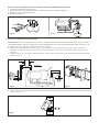
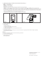
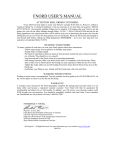
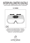
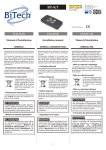
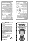
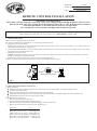
Model No.:
191-707
Vendor No.:
11289
UPC#
792145354369
REMOTE CONTROL INSTALLATION
GENERAL INFORMATION
This remote control is designed to separately control your ceiling fan speed and light brightness. There are four
buttons (Hi, Med, Low, off) to control the fan speed and off. Select “D” or “ON” in the frequency switches to
control the light dimmer or ON/OFF function based on your light bulbs.
The red indicator on the transmitter will light when the button is pressed.
NOTE:
When installing the remote control, be sure your fan is set on "HIGH SPEED" and light is ON.
1. SETTING THE CODE
Remove cover by snapping off from top or bottom.
This unit has 16 different code combinations. To set the code, perform these steps:
a. Setting the code on the transmitter.
Slide frequency switches to your choice of up or down position. (Factory setting is all up. Do not use this position. Use a small screwdriver or
ball point pen to slide firmly up or down (Fig. 1)
b. For use with incandescent bulbs, use the “D” setting for full range dimming. For fans that use Fluorescent or LED bulbs, use the “ON” setting
for the light to have ON/OFF functions only.
c. Setting the code on the receiver
Caution! The frequency switches on the receiver unit are covered with a rubber cover, remove the rubber cover and then place it back after
making any changes to the frequency switches.
Slide frequency switches to the same positions as set on your transmitter. (Fig. 1)
Place the cover back to the transmitter by placing over buttons and snapping into place. (Fig. 1)
ON
HI
ON ECE
LIGHT
MED
1 2 3 4
D
ON
LOW
FAN OFF
ON ECE
1 2 3 4
D
ON
FREQUENCY SWITCHES
RECEIVER
Fig. 1
TRANSMITTER
2. INSTALLING RECEIVER IN CEILING FAN
A: Safety precautions:
WARNING: HIGH VOLTAGE! Disconnect source of electrical power by removing fuse or switching off circuit breaker.
Do not use with solid state fans.
Electrical wiring must meet all local and national electrical code requirements.
Electrical source and fan must be 115/120 volt, 60Hz. Maximum fan motor amps: 1.0 Maximum light watts: 300-incandescent only.
Household electrical power can cause serious injury or death!
B: Installing receiver in fan (Fig. 2):
a. Remove electrical power from the circuit.
b. Remove ceiling fan canopy from the mounting bracket.
c. Disconnect existing wiring between ceiling fan and supply at electrical junction box.
d. Make connections as follows, using the wire nuts supplied (Fig. 3):
CONNECT
TO
Green fan wire…………………….Bare supply wire
Black receiver wire (AC IN L)……Black supply wire
White receiver wire (AC IN N)…...White supply wire
White receiver wire (TO MOTOR N)..White fan wire
Black receiver wire (TO MOTOR L)…Black fan wire
Blue receiver wire (FOR LIGHT)……..Blue light wire
If there are wires with different colors, have this unit installed by qualified licensed electrician.
e.
f.
g.
h.
Push all connected wires up into junction box.
Lay the black antenna wire on top of the receiver, and put the receiver in the mounting bracket. (Fig. 3)
Reinstall all canopy on the mounting bracket
Restore electrical power.
AC SUPPLY
BLACK
WHITE
RECEIVER
RECEIVER
Fig. 2
BLUE
BLUE
BLACK
BLACK
WHITE
WHITE
BARE
Fig. 3
GREEN
3. INSTALLING THE WALL TRANSMITTER
WARNING! HOOK UP “IN SERIES” ONLY. DO NOT CONNECT NEUTRAL SUPPLY WIRE OF ELECTRIC CIRCUIT TO THE
TRANSMITTER WALL SWITCH, DAMAGE TO THE TRANSMITTER WALL SWITCH AND POSSIBLE FIRE COULD OCCUR.
a. Remove the existing wall plate and switch from the wall outlet box.
b. Make the electrical connections as shown in Fig. 4. If your outlet box has a ground wire (Green or Bare Copper) connect the
transmitter’s ground wire directly to one of the screws from the outlet box. Secure all wire connections with the plastic wire nuts
provided.
c. Carefully tuck the wire connections inside the outlet box. Use the screws provided to secure the wall transmitter and wall plate to the
outlet box. (Fig. 5)
INPUT
AC SUPPLY
GROUND
WHITE
BLUE
BLACK
GREEN
BLACK
WALL
CONTROL
BLACK
BLACK
WHITE
WHITE
BLACK
AC120V
BLACK
BLACK
BLUE
BLACK
WHITE
Fig. 4
GROUND
Fig. 5
GREEN
d. Remove cover by snapping off from top or bottom, install 12V battery located in the wall transmitter, Duracell MN21/Eveready A23/GP
23A all 12V. (Fig. 6)
HI
LIGHT
MED
LOW
FAN OFF
ON ECE
1 2 3 4
D
ON
23AE 12V
Fig. 6
4. OPERATION BUTTONS ON THE PANEL OF THE TRANSMITTER (Fig. 7):
HI key – for fan high speed.
MED key – for fan medium speed.
LOW key – for fan low speed.
FAN OFF key – for fan speed off.
OFF-ON Slide Button-This button turns the power Off and On to the Fan and Light(s).
LIGHT key – for fans that use incandescent bulbs, select “D” in the frequency switches, this “LIGHT“ button will control the light
brightness. Hold the “LIGHT“ key down to increase or decrease the light. Tap the “LIGHT“ key quickly to turn the light off or on. If you
press the button in excess of 0.7 seconds it becomes a dimmer. The light varies cyclically in 0.8 seconds. The light key has auto resume. So
it will stay at the same brightness as the last time it was turned off. For fans that use Fluorescent or LED bulbs, select “ON” in the frequency
switches, this “LIGHT“ button will control the light ON/OFF only. (Fig. 8)
YOUR REMOTE NOW HAS FULL CONTROL OF THE FAN AND LIGHT.
ON ECE
HI
LIGHT 1
2 3 4
D
ON
MED
LOW
FAN OFF
ON ECE
1 2 3 4
ON
D
23AE 12V
Fig. 7
OFF
ON
Fig. 8
5. TROUBLE SHOOTING
1. Fails to operate:
a. Power to receiver?
b. Receiver wired correctly?
c. Fan manual speed control in highest position?
d. Light kit switch turned on?
e. Code set at exact same positions in both transmitter and receiver?
2. Won’t operate at distance
If transmitter operates fan/light kit when up close, but not at 20 feet away, try placing the black antenna wire higher; up through
ceiling/outside the junction box.
NOTICE!
Your ceiling fan and light kit assembly must meet the following requirements:
1. Do not use with solid state fans.
2. Electrical rating: 120V 60Hz 3.5A
MAX. motor amps:1.0
MAX. light watts:300
Distributed by Home Depot U.S.A., Inc.
2455 Paces Ferry Rd. N.W.
Atlanta, Georgia 30339
TOLL FREE 1-877-902-5588