1
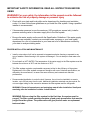
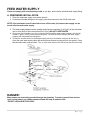
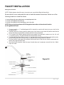
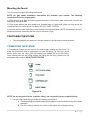
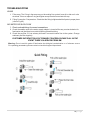
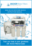
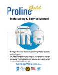
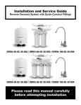
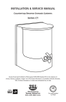
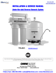
1|Page IMPORTANT SAFETY INFORMATION. READ ALL INSTRUCTIONS BEFORE USING WARNING! For your safety, the information in this manual must be followed to minimize the risk of property damage or personal injury Check with your state and local public works department for plumbing and sanitation codes. You must follow these guidelines as you install the filter system. Using a qualified installer is recommended. If house water pressure is over the maximum (100 pounds per square inch), install a pressure reducing valve in the water supply line to the filter system. Be sure the water supply conforms with the Specification Guidelines. If the water supply conditions are unknown, contact your municipal water company or your local health department for a list of contaminants in your area and a list of laboratories certified by your state to analyze drinking water. PROPER INSTALLATION AND MAINTENANCE Install or store where it will not be exposed to temperatures below freezing or exposed to any type of weather. Water freezing in the system will damage it. Do not attempt to treat water over 90°F. Do not install on HOT WATER. The temperature of the water supply to the filter system must be between the minimum of 40°F and the maximum of 90°F. This filter system contains a replaceable component critical to the efficiency of the system. Replacement of the filter system component should be with one of identical specifications, as defined by the manufacturer, to assure the same efficiency and contaminant reduction performance. Recommended installation is under the sink. However, the unit can be installed in a remote location, up to 20 feet away from the sink. Additional installation materials may be required. Do not use copper tubing for the connection between the filter system and the refrigerator. WARNING: Discard all unused parts and packaging material after installation. Small parts remaining after the installation could be a choke hazard. WARNING: Before using the filter system for the first time, the system must be purged. The filter system cartridge contains a food grade preservative that must be purged from the system. The preservative will give product water an unpleasant taste and odor. 2|Page The system makes a good supply of drinking water each day. How much it will make depends primarily on these things… Feed water pressure limits—pounds per square inch (psi) . . . . . . . . . . . . . . . . . . . . . . 40–100c Feed water temperature limits—minimum/maximum degrees F . . . . . . . . . . . . . . . . … 40– 90 Maximum Total Dissolved Solids (TDS)—parts per million (ppm) . . . . . . . . . . . . . . . . 2000 Installation filter system Instructions BEFORE YOU BEGIN Read these instructions completely and carefully. • IMPORTANT — Save these instructions for local inspector’s use. • IMPORTANT — Observe all governing codes and ordinances. • Note to Installer – Be sure to leave these instructions with the Consumer. • Note to Consumer – Keep these instructions for future reference. • Proper installation is the responsibility of the installer. • Product failure due to improper installation is not covered under the Warranty. • A shutoff valve must be available or added near the installation point. TOOLS AND MATERIALS REQUIRED FOR INSTALLATION • Drill with 1/2″ Drill Bit (type as required) if mounting is needed for faucet • Adjustable Open-End Wrenches • Phillips and Flat Blade Screwdrivers • Utility Knife CONTENTS INCLUDED WITH PRODUCT • Assembly and Tubing • Product Literature (Owner’s Manual and Installation) • Water Supply Inlet Parts Bag • Faucet • Pipe Thread Tape 3|Page Installation Instructions Things to Check before Beginning Installation v 4|Page FEED WATER Municipal water supplies most often will have these qualities. Well water may need conditioning — have the water tested by a water analysis laboratory and get their recommendations for treatment. CAUTION: For water with a hardness greater than 10 grains (at 6.9 pH), the use of a softener is recommended. Failure to install a softener will reduce the life of the filter system. FAUCET The filter product water faucet installs on the sink or on the countertop next to the sink. Often, it is installed in an existing sink spray attachment hole or a hole may be drilled. Space is required underneath for tubing to and from the faucet, and for securing the faucet in place. All faucet connections and installation procedures are done on or above the sink or countertop. Refer to illustration above. BASEMENT INSTALLATION If installing in a basement, leave enough tubing in place during installation to be able to move unit to floor for ease at servicing and making filter/membrane changes. Additional tubing and fittings required 5|Page FEED WATER SUPPLY Check and comply with local plumbing codes as you plan, then install a cold feed water supply fitting. A. PREFERRED INSTALLATION 1. Close the cold water supply valve under the sink. 2. Unscrew the flexible tubing from the supply valve that connects to the COLD water riser. NOTE: If the cold water shut-off valve fails to turn off the water, the house water supply can be turned off at the main water supply. 3. The water supply adapter can be installed at the faucet connection (A of Fig.#1) of the cold water line or at the shut-off valve connection (B of Fig.#1) DO NOT OVERTIGHTEN 4. Disconnect the threaded nut at the connection and thread the water supply adapter, with the flat washer in place, onto the connection and tighten. Connect the White tubing to the water supply adapter with the treaded nut and tighten. 5. Thread the needle valve into the adapter tightly and turn the handle clockwise all the way in. Open the main water supply valve and several house faucets to purge air from the system. Close faucets when water runs smoothly. Turn on cold water supply to the sink faucet and check for leaks on DANGER: Many homes are electrically grounded through the plumbing. To protect yourself from serious injury or fatal shock, use a battery-powered hand drill only to make the hole. DO NOT USE AN ELECTRIC DRILL. 6|Page FAUCET INSTALLATION Drilling the Faucet Hole NOTE: Safety glasses should be worn to protect your eyes while drilling the faucet hole. Be sure there is room underneath the sink to make the needed connections. Select one of the following locations to install the faucet: • In an existing sink spray attachment or soap dispenser hole. • In a hole to be drilled in the sink top. • In a hole to be drilled in the countertop, next to the sink. NOTE: Be sure the faucet base will fit flat against the surface at the selected location so the gasket will seal. 1. For best results, a ½” carbide-tipped drill bit should be used to drill a hole into your sink for the auxiliary faucet. 2. Carefully select the faucet location making sure it will have a neat water fall pattern and that the faucet stud will be accessible from below once the hole is completed. 3. For Porcelain Sink: Before starting the drill motor, apply firm downward pressure on the bit until a crunching occurs. This will help keep the drill bit from moving. 4. For Stainless Steel Sink: Before using a ½” carbide drill bit, an indent should be made with a center punch to keep the drill bit from moving. A small pilot hole will also aid the ½” drill bit. 5. For best results, keep steady firm pressure during the start of the hole will cause excess wear on the bit and progress will be slow. 6. Once the hole is complete, clean the area of metal chips and roughness around the hole. Metal chips will stain Figure # 4 7|Page Mounting the Faucet Your unit comes complete with a long reach faucet. NOTE: Air gap option installation instructions are available upon request. The following instructions is for non-air gap option. 1) Slide chrome cover plate and rubber gasket onto stem of faucet and place faucet onto sink with the stem going through the hole. 2) Place metal washer and lock washer over threaded stem of faucet and tighten nut from under the counter surface to lock the faucet into place. DO NOT OVER TIGHTEN. 3) Connect the blue tube to the faucet stem under the counter and tighten. NOTE: Use a brass insert and plastic ferrule when connecting the blue tube to the faucet (Fig.4) POSITIONING THE SYSTEM 1. The head assembly will stand up in the sink cabinet or can be hung on screws provided. CONNECTING THE SYSTEM 1) Compression fittings may be found on the water supply adapter and the faucet. To make the connections, slide a compression nut onto the tubing (Fig. #8), slip a white plastic sleeve onto the tubing with the beveled end towards the end of the tubing, insert a brass insert into the tubing, bottom the tubing into the fitting, slide the nut up and tighten with a wrench. DO NOT OVER TIGHTEN Figure # 8 NOTE: Do not use brass sleeves on plastic tubing, use only plastic sleeves on plastic tubing. 1. Use the color coded tubing to make the following connections: A. The white tubing connects the water supply adapter to the first clear housing of the head assembly B. The b l u e tubing connects the faucet to the outlet side of the post carbon. 8|Page START-UP PROCEDURE 1. Check to see all connections are made. 2. Check that the pre-filter and pre-carbon sumps are secure using the housing wrench provided. 3. Slowly turn on the water by turning the needle valve counterclockwise. 4. The handle of the faucet should be perpendicular to the spigot (closed). 5. Check for leaks. WARNING: Before using the filter system for the first time, the system must be purged. The filter system cartridge contains a food grade preservative that must be purged from the system. The preservative will give product water an unpleasant taste and odor. If you have any difficulties with the installation, or require additional information on your unit, please consult with our factory technicians. RECOMMENDED MAINTENANCE 1. Sediment Pre-filter: The pre-filter protects the system and should be maintained regularly, a clear housing has been provided for your convenience. The show-white preFilter should be changed when the outside discolors to a cardboard brown color and before the inner surface discolors. The life of the pre- filter will depend upon the condition of your water supply and should be checked at 6-month intervals until a filter life is established (average life 6 months). 2. GAC and Carbon Block: Designed to remove chlorine form the water supply, as well as organic and inorganic substance before entering the TFC membrane (average life 12 months). 3. Post-Carbon: The post-filter should be changed when you experience an unusual taste and/or odor to the water and has a nominal life of 1 year. CHANGING THE SEDIMENT, GAC, AND CARBON BLOCK PRE-CARBON BLOCK PREFILTERS 1. Shut off the feed water to the system by turning the saddle valve on the water supply adapter clockwise until it stops. 2. Press down on faucet handle to relive pressure. 3. Allow 2-3 minutes for pressure in the system to drop 4. Remove the filter sumps with the housing wrench by turning the sump to the left (counterclockwise). If the O- ring in the sump is stretched or worn, it should be replaced to maintain a proper seal 5. Remove the old filter and gaskets (if any) and insert the new filter. 6. Replace the sump onto the cap by turning it to the right (clockwise) until the O-ring makes firm contact, like an oil filter on a car. DO NOT OVER-TIGHTEN. 7. Turn on the feed water to the system by turning the saddle valve at the water supply adapter counter- clockwise. 9|Page TROUBLESHOOTING LEAKS 1. Filter sump: The O-ring in the sump may not be making firm contact, have dirt or hair on it or be stretched. Clean or replace O-ring and tighten sump to make firm contact with cap. 2. Fitting Connection: Compression - Check that the fitting is tightened with all parts in proper place (refer to Fig. #8). NO WATER OR SLOW FLOW 1. Check colored tubing for correct connections 2. Check the saddle valve at the water supply adapter is turned all the way counterclockwise for feed water and that there is no restrictions along the white tubing. 3. Check the pre-filter, if it has a heavy dirt load it can restrict water flow to the system. Change sediment pre-filter regularly. CUSTOMER SATISFACTION IS OF PRIMARY CONCERN, PLEASE CALL IN THE EVENT THERE IS A SERVICE PROBLEM. Warning: Do not use this system if feed water has biological contamination or of unknown source. For operating parameters, please contact our technical support department. 10 | P a g e