1
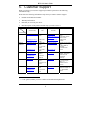
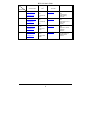
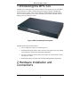
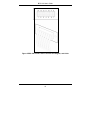
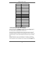
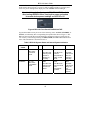
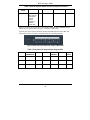
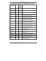
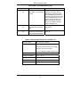
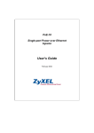
BPS-120
Stand-Alone Backup Power System
User’s Guide
Version 1.0
October 2004
BPS-120 User’s Guide
1. Copyright
Copyright © 2004 by ZyXEL Communications Corporation.
The contents of this publication may not be reproduced in any part or as a whole,
transcribed, stored in a retrieval system, translated into any language, or transmitted in
any form or by any means, electronic, mechanical, magnetic, optical, chemical,
photocopying, manual, or otherwise, without the prior written permission of ZyXEL
Communications Corporation.
Published by ZyXEL Communications Corporation. All rights reserved.
Disclaimer
ZyXEL does not assume any liability arising out of the application or use of any
products, or software described herein. Neither does it convey any license under its
patent rights nor the patent rights of others. ZyXEL further reserves the right to make
changes in any products described herein without notice.
This publication is subject to change without notice.
Trademarks
Trademarks mentioned in this publication are used for identification purposes only and
may be properties of their respective owners.
2.
Interference Statements and
Warnings
FCC Interference Statement
This switch complies with Part 15 of the FCC rules. Operation is subject to the following
two conditions:
(1) This switch may not cause harmful interference.
(2) This switch must accept any interference received, including interference that may
cause undesired operations.
FCC Warning
This equipment has been tested and found to comply with the limits for a Class A digital
switch, pursuant to Part 15 of the FCC Rules. These limits are designed to provide
reasonable protection against harmful interference in a commercial environment. This
equipment generates, uses, and can radiate radio frequency energy and, if not installed
and used in accordance with the instruction manual, may cause harmful interference to
2
BPS-120 User’s Guide
radio communications. Operation of this equipment in a residential area is likely to cause
harmful interference in which case the user will be required to correct the interference at
his own expense.
CE Mark Warning:
This is a class A product. In a domestic environment this product may cause radio
interference in which case the user may be required to take adequate measures.
Taiwanese BSMI (Bureau of Standards, Metrology and Inspection) A
Warning:
Certifications
Refer to the product page at www.zyxel.com.
3. Information for Canadian Users
The Industry Canada label identifies certified equipment. This certification means that
the equipment meets certain telecommunications network protective, operation, and
safety requirements. The Industry Canada does not guarantee that the equipment will
operate to a user's satisfaction.
Before installing this equipment, users should ensure that it is permissible to be
connected to the facilities of the local telecommunications company. The equipment
must also be installed using an acceptable method of connection. In some cases, the
company's inside wiring associated with a single line individual service may be extended
by means of a certified connector assembly. The customer should be aware that the
compliance with the above conditions may not prevent degradation of service in some
situations.
Repairs to certified equipment should be made by an authorized Canadian maintenance
facility designated by the supplier. Any repairs or alterations made by the user to this
equipment, or equipment malfunctions, may give the telecommunications company
cause to request the user to disconnect the equipment.
For their own protection, users should ensure that the electrical ground connections of
the power utility, telephone lines, and internal metallic water pipe system, if present, are
connected together. This precaution may be particularly important in rural areas.
Caution
3
BPS-120 User’s Guide
Users should not attempt to make such connections themselves, but should contact the
appropriate electrical inspection authority, or electrician, as appropriate.
Note
This digital apparatus does not exceed the class A limits for radio noise emissions from
digital apparatus set out in the radio interference regulations of Industry Canada.
4. ZyXEL Limited Warranty
ZyXEL warrants to the original end user (purchaser) that this product is free from any
defects in materials or workmanship for a period of up to two years from the date of
purchase. During the warranty period, and upon proof of purchase, should the product
have indications of failure due to faulty workmanship and/or materials, ZyXEL will, at
its discretion, repair or replace the defective products or components without charge for
either parts or labor, and to whatever extent it shall deem necessary to restore the product
or components to proper operating condition. Any replacement will consist of a new or
re-manufactured functionally equivalent product of equal value, and will be solely at the
discretion of ZyXEL. This warranty shall not apply if the product is modified, misused,
tampered with, damaged by an act of God, or subjected to abnormal working conditions.
NOTE
Repair or replacement, as provided under this warranty, is the exclusive remedy of the
purchaser. This warranty is in lieu of all other warranties, express or implied, including
any implied warranty of merchantability or fitness for a particular use or purpose.
ZyXEL shall in no event be held liable for indirect or consequential damages of any kind
of character to the purchaser.
To obtain the services of this warranty, contact ZyXEL's Service Center for your Return
Material Authorization number (RMA). Products must be returned Postage Prepaid. It is
recommended that the unit be insured when shipped. Any returned products without
proof of purchase or those with an out-dated warranty will be repaired or replaced (at the
discretion of ZyXEL) and the customer will be billed for parts and labor. All repaired or
replaced products will be shipped by ZyXEL to the corresponding return address,
Postage Paid. This warranty gives you specific legal rights, and you may also have other
rights that vary from country to country.
Online Registration
Register online registration at www.zyxel.com for free future product updates and
information.
4
BPS-120 User’s Guide
5. Customer Support
When you contact your customer support representative please have the following
information ready:
Please have the following information ready when you contact customer support.
•
Product model and serial number.
•
Warranty Information.
•
Date that you received your device.
•
Brief description of the problem and the steps you took to solve it.
METHOD
SUPPORT E-MAIL
SALES E-MAIL
TELEPHONE1
FAX
1
WEB SITE
REGULAR MAIL
FTP SITE
LOCATION
WORLDWIDE
[email protected]
+886-3-5783942
www.zyxel.com
www.europe.zyxel.com
ftp.zyxel.com
NORTH
AMERICA
[email protected]
+886-3-5782439
ftp.europe.zyxel.com
[email protected]
+1-800-2554101
www.us.zyxel.com
+1-714-6320882
GERMANY
FRANCE
1
ZyXEL Communications
Inc.
1130 N. Miller St.
Anaheim
CA 92806-2001
U.S.A.
[email protected]
+1-714-6320858
ftp.us.zyxel.com
[email protected]
+49-24056909-0
www.zyxel.de
[email protected]
+49-24056909-99
ZyXEL Deutschland
GmbH. Adenauerstr.
20/A2 D-52146
Wuerselen
Germany
[email protected]
+33 (0)4 72 52
97 97
www.zyxel.fr
ZyXEL France
1 rue des Vergers
Bat. 1 / C
69760 Limonest
France
www.zyxel.es
ZyXEL Communications
Alejandro Villegas 33
1º, 28043 Madrid
Spain
+33 (0)4 72 52
19 20
SPAIN
ZyXEL Communications
Corp.
6 Innovation Road II
Science Park
Hsinchu 300
Taiwan
[email protected]
+34 902 195
420
[email protected]
+34 913 005
345
“+” is the (prefix) number you enter to make an international telephone call.
5
BPS-120 User’s Guide
METHOD
SUPPORT E-MAIL
TELEPHONE1
WEB SITE
SALES E-MAIL
FAX1
FTP SITE
REGULAR MAIL
LOCATION
DENMARK
NORWAY
SWEDEN
FINLAND
[email protected]
+45 39 55 07
00
[email protected]
+45 39 55 07
07
[email protected]
+47 22 80 61
80
[email protected]
+47 22 80 61
81
[email protected]
+46 31 744
7700
[email protected]
+46 31 744
7701
[email protected]
+358-9-47808411
[email protected]
+358-9-4780
8448
6
www.zyxel.dk
ZyXEL Communications
A/S
Columbusvej 5
2860 Soeborg
Denmark
www.zyxel.no
ZyXEL Communications
A/S
Nils Hansens vei 13
0667 Oslo
Norway
www.zyxel.se
ZyXEL Communications
A/S
Sjöporten 4, 41764
Göteborg
Sweden
www.zyxel.fi
ZyXEL Communications
Oy Malminkaari 10
00700 Helsinki
Finland
BPS-120 User’s Guide
Table of Contents
1 Introducing the BPS-120 ................................................................................. 9
2 Hardware Installation and Connections ........................................................ 9
2.1 Desktop Installation................................................................................... 10
2.2 Rack-mounted Installation ........................................................................ 10
2.3 Attaching Power Cables and Connector Definition................................... 12
2.4 Front Panel and LED Displays.................................................................. 14
3 Troubleshooting............................................................................................. 18
7
BPS-120 User’s Guide
1 Introducing the BPS-120
The BPS-120 is a backup power system to which you can connect up to six of ZyXEL’s
devices that have a 12VDC external backup power supply connector. The BPS-120
monitors the power status of the connected devices and immediately provides backup
power to a device that loses power or has a hardware power failure. The BPS-120 can
supply power to one device at a time.
Figure 1 BPS-120 Backup Power System
The BPS-120 has the following features:
•
Six (6) output power ports for connecting devices.
•
Individual front-panel LEDs to show status for each output power port, internal
power hardware, internal fans, and internal temperature.
•
Fast power switchover ensures that a power failure on a connected device does
not cause it to restart.
•
Reduced form factor facilitates rack mounting and high-density deployment.
2 Hardware Installation and
Connections
9
BPS-120 User’s Guide
Do not block the device’s rear panel or the side panel
ventilation holes. Leave space between devices when
stacking.
2.1 Desktop Installation
1.
Set the BPS-120 upside-down on a sturdy level space with a 100/240 VAC
power outlet nearby.
2.
Make sure there is enough clearance near the BPS-120 to allow air circulation,
the attachment of cables, and the power line cord.
3.
Remove the adhesive backing from the supplied rubber feet.
4.
Attach the rubber feet to each corner on the bottom of the BPS-120. These
rubber feet help protect the BPS-120 from shock and/or vibration, and ensure
space bewteen devices when stacking.
5.
Turn the BPS-120 right-side up after you have attached the rubber feet.
Figure 2: Attaching the Rubber Feet
2.2 Rack-mounted Installation
The BPS-120 can be mounted on an EIA standard size, 19-inch rack or in a wiring closet
with other equipment. Follow the steps below to mount your BPS-120 on a standard EIA
rack using the included rack-mounting hardware.
1.
Align one bracket with the holes on one side of the BPS-120 and secure it with
the bracket screws. Similarly, attach the other bracket to the opposite side of the
BPS-120.
10
BPS-120 User’s Guide
Figure 2 Attaching the Rack Mounting Brackets
2.
After attaching both mounting brackets, position the BPS-120 in the rack by
lining up the holes in the brackets with the appropriate holes on the rack. Secure
the BPS-120 to the rack with the rack’s mounting screws.
Figure 3 Rack Mounting the BPS-120
11
BPS-120 User’s Guide
2.3 Attaching Power Cables and Connector
Definition
The BPS-120 includes power connection cables for up to six (6) external devices. The
rear connector pin-out diagram and power signal descriptions are shown in the
following Figure 5, and Table 1 for OUTPUTs (1-6). Backup power is supplied by
inserting power cables into any of the OUTPUTs (1-6) on the rear panel of the BPS120 and into the corresponding power input connector of device(s) such as switches or
routers. The power connector cables may be inserted only one way. There is no need to
worry about inserting the power cables incorrectly as they are keyed for one position.
Backup power for externally connected devices is supplied based upon output port
priority, with OUTPUT 1 having the highest priority. That is, an external device
connected to OUTPUT 1 has backup power priority over devices connected to
OUTPUTs 2-6. OUTPUT 2 has backup power priority over devices connected to
OUTPUTs 3-6, etc.
To turn the BPS-120 on, connect the power line cord to a 100/240 VAC power outlet
and move the rocker switch on the rear panel from the “0” to “1” position. The
STANDBY, PWR, TEMP, and FAN LEDs will then light on the front panel. If they
do not light up see Table 5 for troubleshooting information.
Figure 4 BS-120 Rear Panel Showing OUTPUT Port Power Connections
12
BPS-120 User’s Guide
Figure 5 BPS-120 OUTPUT Port Connector Pin Diagram, and Cable
13
BPS-120 User’s Guide
Table 1 BPS-120 OUTPUT Port Connector(s) (1-6) Pin Definition
PIN NUMBER
DESIGNATION
1
GND
2
N/A
3
12V
4
12V
5
12V
6
12V
7
GND
8
GND
9
N/A
10
BPS present
11
BPS Status0
12
BPS Status1
13
Power good
14
GND
2.4 Front Panel and LED Displays
The BPS-120 defaults to STANDBY mode when the BPS-120 is switched on. Depress
the front panel dual function STANDBY/ACTIVE switch to place the BPS-120 in
active mode, capable of supplying power to remote devices.
System and remote power status information are shown on the front panel of the BPS120 using two groups of LED displays: the first group shown in Figure 6 monitors
internal BPS-120 parameters and the system mode (standby/active), the second group of
LEDs shown in Figure 7 shows status information for each of the six power OUTPUT
ports.
Enabling backup power to any of six external devices is as simple as connecting the
(supplied) system power cables from each OUTPUT 1-6 on the back panel of the BPS120 to external devices. Be sure the BPS-120 is in standby mode (the STANDBY LED)
14
BPS-120 User’s Guide
should be lit) when connecting external devices, then toggle the STANDBY/ACTIVE
mode switch (shown in Figure 6) to active mode to update OUTPUT 1-6 priority and
sense new power readings at the output ports. The ACTIVE LED should light.
You should toggle the front panel STANDBY/ACTIVE switch
after turning the BPS-120 on, forcing it to sense and update
its remote device power readings on OUTPUTs 1-6.
Figure 6 BPS-120 Front Panel STANDBY/ACTIVE
In general the BPS-120 may be in one of the following states: ACTIVE, STANDBY, or
FAULT, as indicated by their corresponding front panel LEDs shown in Figure 6. The
BPS-120 also includes advanced self-diagnostic monitoring features to ensure that its
own circuitry is functioning normally; the PWR, TEMP, and FAN LEDs indicate these
states. This information is described in Table 2.
Table 2 BPS-120 System States and Internal System Indicators
BPS-120
STATE
ACTIVE
STANDBY
PWR
On: The
BPS-120 is
in ACTIVE
mode.
On: The
BPS-120 is
in STANDBY
mode.
TEMP
FAN
GREEN:
GREEN:
GREEN:
The BPS-120
internal power
module is
functioning
normally.
The BPS-120
internal
temperature is
within normal
limits.
The BPS120 internal
fans are
operating
normally.
RED:
RED:
RED:
The BPS-120
internal power
module has
failed.
The BPS-120
has an internal
overtemperature
problem.
The BPS120 internal
fan(s) are
not
operating
properly.
15
BPS-120 User’s Guide
Table 2 BPS-120 System States and Internal System Indicators
BPS-120
STATE
FAULT
PWR
TEMP
FAN
On: The
BPS-120 has
detected an
internal
system
problem or
external
power fault.
Each rear panel OUTPUT port has a corresponding (GREEN, RED, AMBER) LED to
indicate its own state as shown in Figure 7 and Table 3 and Table 4.
Typically the system operator need only monitor the LED indicators on the BPS-120
front panel to ensure externally connected systems are operating normally.
Figure 7 BPS-120 Front Panel DC Output LED Detail
Table 3 Front Panel DC Output Power Output LEDs
NO
CONNECTION
ACTIVE
INACTIVE
POWER
FEEDING
STANDBY
DEVICE
FAULT
GREEN
Off
On
On
On
Off
Off
AMBER
Off
Off
On
Off
On
Off
RED
Off
Off
Off
On
Off
On
16
BPS-120 User’s Guide
Table 4 BPS-120 Front Panel DC Output LEDs State Definitions
PORT LED
INDICATIONS
COLOR
DC
OUTPUT
LED
STATUS
DESCRIPTION
NO
CONNECTION
Green
Off
No external device is connected to OUTPUT
1-6.
NO
CONNECTION
Amber
Off
No external device is connected to OUTPUT
1-6.
NO
CONNECTION
Red
Off
No external device is connected to OUTPUT
1-6.
ACTIVE
Green
On
External device is connected to OUTPUT1-6
but no backup power is supplied.
ACTIVE
Amber
Off
External device is connected to OUTPUT1-6
but no backup power is supplied.
ACTIVE
Red
Off
External device is connected to OUTPUT1-6
but no backup power is supplied.
INACTIVE
Green
On
Output port is unavailable to supply external
power because another is in use.
INACTIVE
Amber
On
Output port is unavailable to supply external
power because another is in use.
INACTIVE
Red
Off
Output port is unavailable to supply external
power because another is in use.
POWER
FEEDING
Green
On
The BPS-120 is providing power to the
connected device.
POWER
FEEDING
Amber
Off
The BPS-120 is providing power to the
connected device.
POWER
FEEDING
Red
On
The BPS-120 is providing power to the
connected device.
STANDBY
Green
Off
The BPS-120 is in standby mode.
STANDBY
Amber
On
The BPS-120 is in standby mode.
STANDBY
Red
Off
The BPS-120 is in standby mode.
DEVICE
FAULT
Green
Off
The BPS-120 has detected an external or
internal fault. See Table 5.
17
BPS-120 User’s Guide
Table 4 BPS-120 Front Panel DC Output LEDs State Definitions
PORT LED
INDICATIONS
COLOR
DC
OUTPUT
LED
STATUS
DESCRIPTION
DEVICE
FAULT
Amber
Off
The BPS-120 has detected an external or
internal fault. See Table 5.
DEVICE
FAULT
Red
On
The BPS-120 has detected an external or
internal fault. See Table 5.
3 Troubleshooting
Make sure that the BPS-120 is plugged into an appropriate AC power supply.
Table 5 BPS-120 Troubleshooting Tips
PROBLEM
The STANBY
LED is off.
CONDITION
Faulty or not connected AC
power supply.
CORRECTIVE ACTION
Make sure you are using the
correct power line cord and it is
plugged into an appropriate
100/240 VAC power supply
receptacle. Check the power line
fuse.
Unplug the power line cord and
plug it in again. Turn the BPS120 on using the rear panel
switch. If the error persists you
should contact your vendor or
Zyxel for servicing.
The STANDBY
LED is on.
The FAULT LED
is red.
The BPS-120 is in standby
mode.
Press the STANDBY/ACTIVE
button to put the BPS-120 into
active mode.
The BPS-120 has an internal
hardware system fault (PWR,
TEMP, or FAN LEDs are
red).
Monitor the PWR, TEMP, and
FAN LEDs, then turn the BPS120 off or disconnect external
devices.
18
BPS-120 User’s Guide
Table 5 BPS-120 Troubleshooting Tips
PROBLEM
CONDITION
CORRECTIVE ACTION
The PWR LED is
red.
DC output power is
unavailable or not operating
properly.
The internal power supply is
defective or the BPS-120 has
detected an overcurrent. Press
the STANDBY/ACTIVE button. If
the FAULT LED does not turn off
and the PWR LED does not turn
green, cycle the power on the
BPS-120 using the rear panel
switch. If the problem persists
replace the BPS-120.
The TEMP LED is
red.
BPS-120 internal
temperature has exceeded
limit.
Reduce the ambient
temperature.
The FAN LED is
red.
Fan speed is wrong (too fast,
too slow) or one of the four
fans has stopped operating.
A fan is defective. Replace the
BPS-120.
Table 6 Technical Specifications for the BPS-120
AC Input Voltage
100 - 240 VAC, 50/60 Hz
Power
Overload protection (power module fuse)
1.8A Max internal universal power supply
120 W per port 12 VDC output
Power consumption 180W maximum (AC)
Operating Temperature
0o C ~ 45o C (32o F ~ 113o F)
Storage Temperature
-25o C ~ 70o C
Operational Humidity
10% ~ 90% (non-condensing)
Weight
4.0 kg
Dimensions (rack)
19” rack mountable width, 1U height
19
BPS-120 User’s Guide
Table 6 Technical Specifications for the BPS-120
Safety
UL 60950-1
CSA 60950-1
EN60950-1
IEC-60950-1
EMC
FCC Part15 (Class A)
CE EMC (Class A)
20