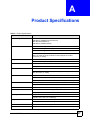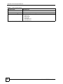
1
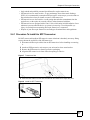
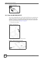
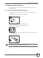
MC1000-SFP-FP
Ethernet-to-Fiber Media Converter
User’s Guide
Version 1.00
4/2007
Edition 1
www.zyxel.com
About This User's Guide
About This User's Guide
Intended Audience
This manual is intended for people who want to configure the MC1000-SFP-FP using the web
configurator. A basic knowledge of computer networking and IP addresses will be helpful.
Related Documentation
ZyXEL Web Site
Please refer to www.zyxel.com for product certifications.
User Guide Feedback
Help us help you. Send all User Guide-related comments, questions or suggestions for
improvement to the following address, or use e-mail instead. Thank you!
The Technical Writing Team,
ZyXEL Communications Corp.,
6 Innovation Road II,
Science-Based Industrial Park,
Hsinchu, 300, Taiwan.
E-mail: [email protected]
MC1000-SFP-FP User’s Guide
3
Safety Warnings
Safety Warnings
1
For your safety, be sure to read and follow all warning notices and instructions.
• Do NOT use this product near water, for example, in a wet basement or near a swimming
pool.
• Do NOT expose your device to dampness, dust or corrosive liquids.
• Do NOT store things on the device.
• Do NOT install, use, or service this device during a thunderstorm. There is a remote risk
of electric shock from lightning.
• Connect ONLY suitable accessories to the device.
• Do NOT open the device or unit. Opening or removing covers can expose you to
dangerous high voltage points or other risks. ONLY qualified service personnel should
service or disassemble this device. Please contact your vendor for further information.
• ONLY qualified service personnel should service or disassemble this device.
• Make sure to connect the cables to the correct ports.
• Place connecting cables carefully so that no one will step on them or stumble over them.
• Always disconnect all cables from this device before servicing or disassembling.
• Use ONLY an appropriate power adaptor or cord for your device.
• Connect the power adaptor or cord to the right supply voltage (for example, 110V AC in
North America or 230V AC in Europe).
• Do NOT allow anything to rest on the power adaptor or cord and do NOT place the
product where anyone can walk on the power adaptor or cord.
• Do NOT use the device if the power adaptor or cord is damaged as it might cause
electrocution.
• If the power adaptor or cord is damaged, remove it from the power outlet.
• Do NOT attempt to repair the power adaptor or cord. Contact your local vendor to order a
new one.
• Do not use the device outside, and make sure all the connections are indoors. There is a
remote risk of electric shock from lightning.
• CAUTION: RISK OF EXPLOSION IF BATTERY (on the motherboard) IS REPLACED
BY AN INCORRECT TYPE. DISPOSE OF USED BATTERIES ACCORDING TO
THE INSTRUCTIONS. Dispose them at the applicable collection point for the recycling
of electrical and electronic equipment. For detailed information about recycling of this
product, please contact your local city office, your household waste disposal service or the
store where you purchased the product.
• Do NOT obstruct the device ventilation slots, as insufficient airflow may harm your
device.
This product is recyclable. Dispose of it properly.
4
MC1000-SFP-FP User’s Guide
Safety Warnings
MC1000-SFP-FP User’s Guide
5
Safety Warnings
6
MC1000-SFP-FP User’s Guide
Table of Contents
Table of Contents
About This User's Guide .......................................................................................................... 3
Safety Warnings........................................................................................................................ 4
Table of Contents...................................................................................................................... 7
List of Figures ........................................................................................................................... 9
List of Tables........................................................................................................................... 11
Chapter 1
Introduction ............................................................................................................................ 13
1.1 Overview .............................................................................................................................. 13
1.1.1 Link-Fault Signaling (LFS) .......................................................................................... 13
1.1.2 Fiber Cable Protection ............................................................................................... 14
Chapter 2
Fiber-optic Connection........................................................................................................... 15
2.1 Overview .............................................................................................................................. 15
2.2 Open the MC1000-SFP-FP ................................................................................................. 15
2.3 DIP Switch 1 ........................................................................................................................ 16
2.4 Install A Transceiver ............................................................................................................ 16
2.4.1 Procedure To Install An SFP Transceiver .................................................................. 17
2.5 Install Fiber-optic Cable ....................................................................................................... 18
2.5.1 Attach Wire Mounts .................................................................................................... 18
2.5.2 Insert Fiber-optic Cable .............................................................................................. 19
2.5.3 Connect The Fiber-optic Cable To The Transceiver ................................................... 19
2.6 Close the MC1000-SFP-FP ................................................................................................. 20
2.7 Replacing An SFP Transceiver ............................................................................................ 21
2.7.1 Procedure To Remove An SFP Transceiver .............................................................. 21
Chapter 3
Deploying the MC1000-SFP-FP.............................................................................................. 23
3.1 Overview .............................................................................................................................. 23
3.2 LAN Connection .................................................................................................................. 23
3.3 Power Connection ............................................................................................................... 23
3.4 Front Panel LEDs ................................................................................................................ 24
3.5 Wall-mounting Instructions .................................................................................................. 25
Appendix A Product Specifications......................................................................................... 27
MC1000-SFP-FP User’s Guide
7
Table of Contents
Appendix B Legal Information ................................................................................................ 29
Appendix C Customer Support............................................................................................... 31
8
MC1000-SFP-FP User’s Guide
List of Figures
List of Figures
Figure 1 MC1000-SFP-FP Example Application 1 ................................................................................. 13
Figure 2 MC1000-SFP-FP Example Application 2 ................................................................................. 13
Figure 3 No Link-Fault Signaling ............................................................................................................ 14
Figure 4 With Link-Fault Signaling .......................................................................................................... 14
Figure 5 Remove The Housing Screws .................................................................................................. 15
Figure 6 Open The Cover ....................................................................................................................... 16
Figure 7 Transceiver Slot ........................................................................................................................ 17
Figure 8 Install An SFP Transceiver ....................................................................................................... 17
Figure 9 Lock Transceiver ...................................................................................................................... 18
Figure 10 Attach Wire Mounts. ............................................................................................................... 19
Figure 11 Wrap Fiber-optic Cable ........................................................................................................... 19
Figure 12 Insert Cable ............................................................................................................................ 20
Figure 13 Close The Cover .................................................................................................................... 20
Figure 14 Replace Housing Cover Screws ............................................................................................. 20
Figure 15 Remove Fiber-optic Cable ...................................................................................................... 21
Figure 16 Unlock The Transceiver .......................................................................................................... 21
Figure 17 Remove Transceiver .............................................................................................................. 21
Figure 18 LAN Connection ..................................................................................................................... 23
Figure 19 Power Connection .................................................................................................................. 24
Figure 20 MC1000-SFP-FP LEDs ......................................................................................................... 25
Figure 21 Wall-mounting Example .......................................................................................................... 26
MC1000-SFP-FP User’s Guide
9
List of Figures
10
MC1000-SFP-FP User’s Guide
List of Tables
List of Tables
Table 1 Front Panel LEDs ...................................................................................................................... 25
Table 2 Product Specifications ............................................................................................................... 27
MC1000-SFP-FP User’s Guide
11
List of Tables
12
MC1000-SFP-FP User’s Guide
CHAPTER
1
Introduction
1.1 Overview
The MC1000-SFP-FP is a Gigabit Ethernet-to-Fiber media converter. It can convert
transmissions between 10/100/1000 Base-X UTP (Unshielded Twisted Pair) copper media and
1000 Base-X SFP (Small Form-factor Pluggable, also known as mini-GBIC) fiber media.
In the next example (G is the Gigabit Ethernet link and F is the fiber link), the MC1000-SFPFP functions as a high-speed bridge between switches connecting workgroups in branch
offices for instance.
Figure 1 MC1000-SFP-FP Example Application 1
In the next example (G is the Gigabit Ethernet link and F is the fiber link), the MC1000-SFPFP allows high-speed access to servers for various workgroups within an enterprise.
Figure 2 MC1000-SFP-FP Example Application 2
1.1.1 Link-Fault Signaling (LFS)
The MC1000-SFP-FP supports Link-Fault Signaling (LFS). LFS monitors both copper and
fiber segments and informs other segments if one segment goes down (the LFS LED also
lights).
MC1000-SFP-FP User’s Guide
13
Chapter 1 Introduction
For example, if LFS is disabled and one side of a link fails (down arrow), the other segments
will keep on transmitting packets (up arrows) and wait for responses that will never arrive.
Figure 3 No Link-Fault Signaling
With LFS enabled, a link down detected on the Ethernet port will force a link down on the
fiber port and vice-versa. The up link will stop transmitting and turn off as soon as the remote
link is down.
Figure 4 With Link-Fault Signaling
1.1.2 Fiber Cable Protection
The MC1000-SFP-FP comes with wire mounts that keep fiber-optic cable from easily
breaking by allowing you to wrap it within the MC1000-SFP-FP.
14
MC1000-SFP-FP User’s Guide
CHAPTER
2
Fiber-optic Connection
2.1 Overview
To make the MC1000-SFP-FP fiber-optic connection you need to:
1
2
3
4
5
6
7
1
Open the MC1000-SFP-FP
Disable DIP switch 1 (LFS)
Install an SFP transceiver
Attach the wire mounts
Insert a fiber-optic cable through a bushing and wrap it around the wire mounts
Connect the fiber-optic cable to the SFP transceiver
Enable DIP switch 1 (LFS)
Only qualified technicians should perform these actions! Please skip this
chapter if you are not a qualified technician.
2.2 Open the MC1000-SFP-FP
1 First remove both screws from the housing.
Figure 5 Remove The Housing Screws
2 Then lift open the cover as shown.
MC1000-SFP-FP User’s Guide
15
Chapter 2 Fiber-optic Connection
Figure 6 Open The Cover
2.3 DIP Switch 1
The MC1000-SFP-FP supports Link-Fault Signaling (LFS). LFS monitors both copper and
fiber segments and informs other segments if one segment goes down (the LFS LED also
lights). See Section 1.1.1 on page 13 for more information on LFS.
Use DIP switch 1 to enable or disable Link-Fault Signaling (LFS). The DIP switches are
located on the printed circuit board inside the MC1000-SFP-FP.
"
Only DIP switch 1 has functionality. Ignore the other DIP switches.
• Set DIP switch 1 to the OFF position when installing cables or when testing the network
connection.
• Set DIP switch 1 to the ON position after you’ve installed cables and tested that the
connection is working correctly.
2.4 Install A Transceiver
The MC1000-SFP-FP supports MSA (Multi-Source Agreement) compliant SFP transceivers.
Inside the MC1000-SFP-FP, there is a slot for an SFP transceiver with an LC-type connector.
SFP transceivers provide duplex single-mode or multi-mode connections. See the product
specifications appendix for a list of transceivers supported at the time of writing.
1
16
Please observe the following warnings when working with transceivers!
MC1000-SFP-FP User’s Guide
Chapter 2 Fiber-optic Connection
• Only trained and qualified personnel should install or replace transceivers.
• SFP transceivers are static sensitive. To prevent damage from electrostatic discharge
(ESD), it is recommended you attach an ESD preventive wrist strap to your wrist and to a
bare metal surface when you install or remove a SFP transceiver.
• SFP transceivers are dust sensitive. Avoid getting dust and other contaminants into the
optical bores, as the optics do not work correctly when obstructed with dust.
• SFP transceivers are equipped with a Class 1 laser, which emits invisible radiation. Laser
radiation is present when the device or system is powered up. To avoid possible eye
injury, do not look into an operating fiber-optic transceiver’s connectors.
• Dispose of your fiber-optic transceivers according to all national laws and regulations.
2.4.1 Procedure To Install An SFP Transceiver
Do NOT remove and install an SFP transceiver more often than is absolutely necessary. Doing
so may shorten the useful life of the SFP transceiver.
1 Disconnect all fiber-optic cables from an SFP transceiver before installing or removing
it.
2 Attach an ESD preventive wrist strap to your wrist and to a bare metal surface.
3 Remove the SFP transceiver from its protective packaging.
4 Align the SFP transceiver in front of the slot opening on a device.
Figure 7 Transceiver Slot
5 Insert the SFP transceiver into the slot until the SFP transceiver snaps into place.
Figure 8 Install An SFP Transceiver
.
MC1000-SFP-FP User’s Guide
17
Chapter 2 Fiber-optic Connection
"
SFP transceiver installation orientation varies depending on your device. Your
SFP transceiver comes with a mechanism that prevents incorrect insertion. Do
NOT force or twist the SFP transceiver into a slot.
6 Lock the transceiver into place (if your transceiver has a locking mechanism).
Figure 9 Lock Transceiver
"
See the transceiver User’s Guide for more information.
2.5 Install Fiber-optic Cable
Follow these procedures to install the fiber-optic cable.
2.5.1 Attach Wire Mounts
The purpose of the wire mounts is to securely wrap extra length of fiber optic cable you may
have within the MC1000-SFP-FP in order to prevent it from being damaged. Remove the
adhesive cover from the wire mounts and attach them to the sides of the MC1000-SFP-FP as
shown.
18
MC1000-SFP-FP User’s Guide
Chapter 2 Fiber-optic Connection
Figure 10 Attach Wire Mounts.
2.5.2 Insert Fiber-optic Cable
The MC1000-SFP-FP has holes (labelled A in the following figure) through which you may
insert fiber-optic cable.
1 Insert a bushing into a hole through which you will insert the fiber-optic cable. The
bushing sheathes the cable, holds it in place and covers the hole.
2 Create a hole in the bushing and thread the fiber-optic cable through it.
3 Insert bushings into the remaining vacant holes to cover them.
4 Wrap excessive fiber-optic cable around the inside of the MC1000-SFP-FP using the
wire mounts as shown in the following figure.
Figure 11 Wrap Fiber-optic Cable
A
A
A
A
2.5.3 Connect The Fiber-optic Cable To The Transceiver
1 Remove the dust plugs from the SFP transceiver and the cables.
2 Insert the end of the fiber-optic cable into the SFP transceiver.
MC1000-SFP-FP User’s Guide
19
Chapter 2 Fiber-optic Connection
Figure 12 Insert Cable
2.6 Close the MC1000-SFP-FP
After you have disabled DIP switch 1 (LFS), installed the SFP transceiver, attached the wire
mounts, threaded fiber-optic cable though a bushing, wrapped excessive fiber-optic cable
around the wire mounts, inserted the fiber-optic cable into the SFP transceiver and enabled
DIP switch 1 (LFS) again, you should close the housing cover and secure it with the same
screws you removed as shown in Section 2.2 on page 15.
1 Close the cover as shown.
Figure 13 Close The Cover
2 Screw the cover back on the housing as shown.
Figure 14 Replace Housing Cover Screws
20
MC1000-SFP-FP User’s Guide
Chapter 2 Fiber-optic Connection
2.7 Replacing An SFP Transceiver
To replace an SFP transceiver, first remove the original one and then insert a new one as
documented previously.
2.7.1 Procedure To Remove An SFP Transceiver
1 Attach an ESD preventive wrist strap to your wrist and to a bare metal surface on the
chassis.
2 Disconnect the fiber-optic cable from the SFP transceiver.
Figure 15 Remove Fiber-optic Cable
3 Insert the dust plug into the port on the SFP transceiver.
4 Pull the latch out and down to unlock the SFP transceiver.
Figure 16 Unlock The Transceiver
5 Using your thumb and index finger, grasp both sides of the transceiver and carefully
slide it out of the slot.
Figure 17 Remove Transceiver
"
Do NOT force or twist the transceiver out of a slot.
MC1000-SFP-FP User’s Guide
21
Chapter 2 Fiber-optic Connection
22
MC1000-SFP-FP User’s Guide
CHAPTER
3
Deploying the MC1000-SFP-FP
3.1 Overview
In this chapter we show you how to:
•
•
•
•
Make the LAN connection
Make the power connection and turn the MC1000-SFP-FP on
Use the LEDs to check correct operation of the MC1000-SFP-FP
Mount the MC1000-SFP-FP on a wall.
The MC1000-SFP-FP can also be placed on a desktop. Make sure that there is proper
MC1000-SFP-FP dissipation from and adequate ventilation around the device. Do not place
heavy objects on the MC1000-SFP-FP.
3.2 LAN Connection
Connect the Ethernet port on the rear of the MC1000-SFP-FP to a computer, switch or router
on your network using an Ethernet cable. The port is Auto MDI/MDI-X meaning you can use
either a straight-through or crossover Ethernet cable. Use an 8-wire Ethernet Cat 5e cable for
Gigabit connections.
Figure 18 LAN Connection
3.3 Power Connection
Connect one end of the power cord to the power socket in the MC1000-SFP-FP and the other
end to a power source.
MC1000-SFP-FP User’s Guide
23
Chapter 3 Deploying the MC1000-SFP-FP
"
Be careful not to damage the fiber optic cables if you have already connected
them to the SFP transceiver.
To turn the MC1000-SFP-FP on, connect the external power supply to a power outlet.
Figure 19 Power Connection
3.4 Front Panel LEDs
The MC1000-SFP-FP LEDs are on the top. Look at them to quickly check the status of the
MC1000-SFP-FP.
24
MC1000-SFP-FP User’s Guide
Chapter 3 Deploying the MC1000-SFP-FP
Figure 20 MC1000-SFP-FP LEDs
Table 1 Front Panel LEDs
LED
COLOR
STATUS
DESCRIPTION
PWR
Green
Off
The MC1000-SFP-FP is turned off.
On
The MC1000-SFP-FP is turned on.
Off
Fiber-optic and Ethernet links to the MC1000-SFP-FP are
operating normally.
On
There is a disruption or break in the fiber-optic or Ethernet
link to the MC1000-SFP-FP.
Off
The SFP transceiver is not connected to a fiber-optic link or
the link is down.
On
The SFP transceiver is connected to a fiber-optic link.
Flashing
The MC1000-SFP-FP is sending or receiving packets on this
port.
Off
The Ethernet port is not connected to an Ethernet device or
the link is down.
On
The Ethernet port is connected to an Ethernet device.
Flashing
The MC1000-SFP-FP is sending or receiving packets on this
port.
Off
There is no traffic on this port.
On
The MC1000-SFP-FP is sending or receiving packets at
1000 Mbps.
LFS
FIBER LNK/
ACT
COPPER LNK/
ACT
1000
Red
Green
Green
Green
3.5 Wall-mounting Instructions
Complete the following steps to hang your MC1000-SFP-FP on a wall.
1 Select a position free of obstructions on a sturdy wall.
2 Drill two holes just big enough for M3 size screws.
MC1000-SFP-FP User’s Guide
25
Chapter 3 Deploying the MC1000-SFP-FP
1
Be careful to avoid damaging pipes or cables located inside the wall when
drilling holes for the screws.
3 Do not insert the screws all the way into the wall. Leave a small gap of about 0.5 cm
between the heads of the screws and the wall.
4 Make sure the screws are snugly fastened to the wall. They need to hold the weight of
the MC1000-SFP-FP with the connection cables.
5 Align the holes on the back of the MC1000-SFP-FP with the screws on the wall. Hang
the MC1000-SFP-FP on the screws.
Figure 21 Wall-mounting Example
26
MC1000-SFP-FP User’s Guide
APPENDIX
A
Product Specifications
Table 2 Product Specifications
SPECIFICATION
DESCRIPTION
Standards Supported
IEEE 802.3 (10BASE-T Ethernet)
IEEE 802.3u (100BASE-TX/ Fast Ethernet)
IEEE 802.3ab (1000Base-T)
IEEE 802.3z (1000Base-SX/LX)
Interfaces
One 10/100/1000 Mbps Ethernet port
Auto MDI/MDI-X support on RJ-45 port
One SFP slot for Gigabit Ethernet link
Extends distances up to 500m (1,650ft) for multi-mode fiber module
80km (317,625ft) for single-mode fiber module (depends on the SFP
transceiver you install)
Management
Alarm LED illuminates to indicate link failure
Status LEDs for easy monitoring of device’s status
Connectors
One RJ-45
One Fiber SFP
Maximum Distances allowed
UTP: 100m (Cat 5/5e/6)
Fiber: SFP; up to 500m (multi-mode), 80km (single-mode; depends on the
SFP transceiver you install)
Cables
Single-mode fiber: 9/125um
Multi-mode fiber: 50/125 or 62.5/125um
Copper: Cat 5/5E/6. Use 8-wire Ethernet cable for Gigabit Ethernet
Data Rates
Fiber: 1000 Mbps
Copper: 10/100/1000Mbps
DIP Switches
DIP 1 – LFS: Enable/disable Link Fault Signaling (LFS)
Power
12V DC, 0.8A, external power supply adapter
Frequency: 50 Hz to 60 Hz
Operating Environment
Temperature: 0°C to 45°C
Humidity: 10% to 90%, non-condensing
Storage Environment
Temperature: -20°C to 70°C
Humidity: 5% to 90%, non-condensing
Emissions
FCC Part 15 of Class B & CE approved
Dimensions
194 x 130 x 26 mm (L x W x H)
MC1000-SFP-FP User’s Guide
27
Appendix A Product Specifications
Table 2 Product Specifications
SPECIFICATION
DESCRIPTION
Weight
292g
SFP Transceivers
Supported
A.
28
transceiversA
Use 3.3V power input and LC-type connectors.
•
•
•
•
•
•
SFP-SX
SFP-LX-10
SFP-LHX-40
SFP-ZX-80
SFP-BX1310-10
SFP-BX1490-10
Supported at the time of writing.
MC1000-SFP-FP User’s Guide
APPENDIX
B
Legal Information
Copyright
Copyright © 2007 by ZyXEL Communications Corporation.
The contents of this publication may not be reproduced in any part or as a whole, transcribed,
stored in a retrieval system, translated into any language, or transmitted in any form or by any
means, electronic, mechanical, magnetic, optical, chemical, photocopying, manual, or
otherwise, without the prior written permission of ZyXEL Communications Corporation.
Published by ZyXEL Communications Corporation. All rights reserved.
Disclaimer
ZyXEL does not assume any liability arising out of the application or use of any products, or
software described herein. Neither does it convey any license under its patent rights nor the
patent rights of others. ZyXEL further reserves the right to make changes in any products
described herein without notice. This publication is subject to change without notice.
Certifications
Federal Communications Commission (FCC) Interference Statement
The device complies with Part 15 of FCC rules. Operation is subject to the following two
conditions:
• This device may not cause harmful interference.
• This device must accept any interference received, including interference that may cause
undesired operations.
This device has been tested and found to comply with the limits for a Class B digital device
pursuant to Part 15 of the FCC Rules. These limits are designed to provide reasonable
protection against harmful interference in a residential installation. This device generates,
uses, and can radiate radio frequency energy, and if not installed and used in accordance with
the instructions, may cause harmful interference to radio communications. However, there is
no guarantee that interference will not occur in a particular installation.
Notices
Changes or modifications not expressly approved by the party responsible for compliance
could void the user's authority to operate the equipment.
This Class B digital apparatus complies with Canadian ICES-003.
MC1000-SFP-FP User’s Guide
29
Appendix B Legal Information
Cet appareil numérique de la classe B est conforme à la norme NMB-003 du Canada.
Viewing Certifications
1 Go to http://www.zyxel.com.
2 Select your product on the ZyXEL home page to go to that product's page.
3 Select the certification you wish to view from this page.
ZyXEL warrants to the original end user (purchaser) that this product is free from any defects
in materials or workmanship for a period of up to two years from the date of purchase. During
the warranty period, and upon proof of purchase, should the product have indications of failure
due to faulty workmanship and/or materials, ZyXEL will, at its discretion, repair or replace the
defective products or components without charge for either parts or labor, and to whatever
extent it shall deem necessary to restore the product or components to proper operating
condition. Any replacement will consist of a new or re-manufactured functionally equivalent
product of equal or higher value, and will be solely at the discretion of ZyXEL. This warranty
shall not apply if the product has been modified, misused, tampered with, damaged by an act
of God, or subjected to abnormal working conditions.
Note
Repair or replacement, as provided under this warranty, is the exclusive remedy of the
purchaser. This warranty is in lieu of all other warranties, express or implied, including any
implied warranty of merchantability or fitness for a particular use or purpose. ZyXEL shall in
no event be held liable for indirect or consequential damages of any kind to the purchaser.
To obtain the services of this warranty, contact ZyXEL's Service Center for your Return
Material Authorization number (RMA). Products must be returned Postage Prepaid. It is
recommended that the unit be insured when shipped. Any returned products without proof of
purchase or those with an out-dated warranty will be repaired or replaced (at the discretion of
ZyXEL) and the customer will be billed for parts and labor. All repaired or replaced products
will be shipped by ZyXEL to the corresponding return address, Postage Paid. This warranty
gives you specific legal rights, and you may also have other rights that vary from country to
country.
Registration
Register your product online to receive e-mail notices of firmware upgrades and information
at www.zyxel.com for global products, or at www.us.zyxel.com for North American products.
30
MC1000-SFP-FP User’s Guide
APPENDIX
C
Customer Support
Please have the following information ready when you contact customer support.
Required Information
•
•
•
•
Product model and serial number.
Warranty Information.
Date that you received your device.
Brief description of the problem and the steps you took to solve it.
Corporate Headquarters (Worldwide)
•
•
•
•
•
•
•
Support E-mail: [email protected]
Sales E-mail: [email protected]
Telephone: +886-3-578-3942
Fax: +886-3-578-2439
Web Site: www.zyxel.com, www.europe.zyxel.com
FTP Site: ftp.zyxel.com, ftp.europe.zyxel.com
Regular Mail: ZyXEL Communications Corp., 6 Innovation Road II, Science Park,
Hsinchu 300, Taiwan
Costa Rica
•
•
•
•
•
•
•
Support E-mail: [email protected]
Sales E-mail: [email protected]
Telephone: +506-2017878
Fax: +506-2015098
Web Site: www.zyxel.co.cr
FTP Site: ftp.zyxel.co.cr
Regular Mail: ZyXEL Costa Rica, Plaza Roble Escazú, Etapa El Patio, Tercer Piso, San
José, Costa Rica
Czech Republic
•
•
•
•
•
E-mail: [email protected]
Telephone: +420-241-091-350
Fax: +420-241-091-359
Web Site: www.zyxel.cz
Regular Mail: ZyXEL Communications, Czech s.r.o., Modranská 621, 143 01 Praha 4 Modrany, Ceská Republika
MC1000-SFP-FP User’s Guide
31
Appendix C Customer Support
Denmark
•
•
•
•
•
•
Support E-mail: [email protected]
Sales E-mail: [email protected]
Telephone: +45-39-55-07-00
Fax: +45-39-55-07-07
Web Site: www.zyxel.dk
Regular Mail: ZyXEL Communications A/S, Columbusvej, 2860 Soeborg, Denmark
Finland
•
•
•
•
•
•
Support E-mail: [email protected]
Sales E-mail: [email protected]
Telephone: +358-9-4780-8411
Fax: +358-9-4780 8448
Web Site: www.zyxel.fi
Regular Mail: ZyXEL Communications Oy, Malminkaari 10, 00700 Helsinki, Finland
France
•
•
•
•
•
E-mail: [email protected]
Telephone: +33-4-72-52-97-97
Fax: +33-4-72-52-19-20
Web Site: www.zyxel.fr
Regular Mail: ZyXEL France, 1 rue des Vergers, Bat. 1 / C, 69760 Limonest, France
Germany
•
•
•
•
•
•
Support E-mail: [email protected]
Sales E-mail: [email protected]
Telephone: +49-2405-690969
Fax: +49-2405-6909-99
Web Site: www.zyxel.de
Regular Mail: ZyXEL Deutschland GmbH., Adenauerstr. 20/A2 D-52146, Wuerselen,
Germany
Hungary
•
•
•
•
•
•
Support E-mail: [email protected]
Sales E-mail: [email protected]
Telephone: +36-1-3361649
Fax: +36-1-3259100
Web Site: www.zyxel.hu
Regular Mail: ZyXEL Hungary, 48, Zoldlomb Str., H-1025, Budapest, Hungary
Kazakhstan
• Support: http://zyxel.kz/support
• Sales E-mail: [email protected]
32
MC1000-SFP-FP User’s Guide
Appendix C Customer Support
•
•
•
•
Telephone: +7-3272-590-698
Fax: +7-3272-590-689
Web Site: www.zyxel.kz
Regular Mail: ZyXEL Kazakhstan, 43, Dostyk ave.,Office 414, Dostyk Business Centre,
050010, Almaty, Republic of Kazakhstan
North America
•
•
•
•
•
•
•
Support E-mail: [email protected]
Sales E-mail: [email protected]
Telephone: +1-800-255-4101, +1-714-632-0882
Fax: +1-714-632-0858
Web Site: www.us.zyxel.com
FTP Site: ftp.us.zyxel.com
Regular Mail: ZyXEL Communications Inc., 1130 N. Miller St., Anaheim, CA 928062001, U.S.A.
Norway
•
•
•
•
•
•
Support E-mail: [email protected]
Sales E-mail: [email protected]
Telephone: +47-22-80-61-80
Fax: +47-22-80-61-81
Web Site: www.zyxel.no
Regular Mail: ZyXEL Communications A/S, Nils Hansens vei 13, 0667 Oslo, Norway
Poland
•
•
•
•
•
E-mail: [email protected]
Telephone: +48 (22) 333 8250
Fax: +48 (22) 333 8251
Web Site: www.pl.zyxel.com
Regular Mail: ZyXEL Communications, ul. Okrzei 1A, 03-715 Warszawa, Poland
Russia
•
•
•
•
•
•
Support: http://zyxel.ru/support
Sales E-mail: [email protected]
Telephone: +7-095-542-89-29
Fax: +7-095-542-89-25
Web Site: www.zyxel.ru
Regular Mail: ZyXEL Russia, Ostrovityanova 37a Str., Moscow, 117279, Russia
Spain
•
•
•
•
Support E-mail: [email protected]
Sales E-mail: [email protected]
Telephone: +34-902-195-420
Fax: +34-913-005-345
MC1000-SFP-FP User’s Guide
33
Appendix C Customer Support
• Web Site: www.zyxel.es
• Regular Mail: ZyXEL Communications, Arte, 21 5ª planta, 28033 Madrid, Spain
Sweden
•
•
•
•
•
•
Support E-mail: [email protected]
Sales E-mail: [email protected]
Telephone: +46-31-744-7700
Fax: +46-31-744-7701
Web Site: www.zyxel.se
Regular Mail: ZyXEL Communications A/S, Sjöporten 4, 41764 Göteborg, Sweden
Ukraine
•
•
•
•
•
•
Support E-mail: [email protected]
Sales E-mail: [email protected]
Telephone: +380-44-247-69-78
Fax: +380-44-494-49-32
Web Site: www.ua.zyxel.com
Regular Mail: ZyXEL Ukraine, 13, Pimonenko Str., Kiev, 04050, Ukraine
United Kingdom
•
•
•
•
•
•
•
Support E-mail: [email protected]
Sales E-mail: [email protected]
Telephone: +44-1344 303044, 08707 555779 (UK only)
Fax: +44-1344 303034
Web Site: www.zyxel.co.uk
FTP Site: ftp.zyxel.co.uk
Regular Mail: ZyXEL Communications UK, Ltd.,11 The Courtyard, Eastern Road,
Bracknell, Berkshire, RG12 2XB, United Kingdom (UK)
“+” is the (prefix) number you dial to make an international telephone call.
34
MC1000-SFP-FP User’s Guide