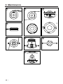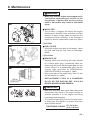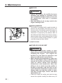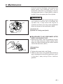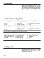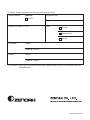
1
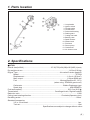
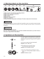
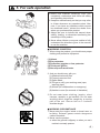
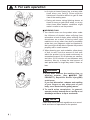
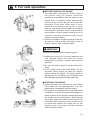
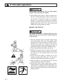
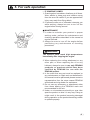
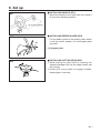
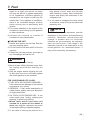
848-J25-93A1 (704) OWNER / OPERATOR MANUAL LINE TRIMMER BT251 WARNING WARNING The engine exhaust from this product contains chemicals known to the State of California to cause cancer, birth defects or other reproductive harm. Before using our products, please read this manual carefully to understand the proper use of your unit. SAFETY FIRST Instructions contained in warnings within this manual marked with a symbol concern critical points which must be taken into consideration to prevent possible serious bodily injury, and for this reason you are requested to read all such instructions carefully and follow them without fail. ■ WARNINGS IN THE MANUAL WARNING This mark indicates instructions which must be followed in order to prevent accidents which could lead to serious bodily injury or death. IMPORTANT This mark indicates instructions which must be followed, or it leads to mechanical failure, breakdown, or damage. NOTE This mark indicates hints or directions useful in the use of the product. 1. 2. 3. 4. 5. 6. 7. 8. 9. 10. 11. 12. 13. CONTENTS Parts location …………………………………3 Specifications …………………………………3 Warning labels on the machine ……………4 Symbols on the machine ……………………4 For safe operation ……………………………5 Set up …………………………………………11 Fuel……………………………………………12 Operation ……………………………………14 Maintenance …………………………………17 Storage ………………………………………22 Troubleshooting guide ………………………22 Disposal ………………………………………22 Limited warranty ……………………………23 1. Parts location 1. 2. 3. 4. 5. 6. 7. 8. 9. 10. 11. 12. 13. 14. Loop handle Ignition switch Throttle cable Throttle lever Drive shaft housing Debris guard Cutting line head Bearing case Spark arrester Starter knob Fuel tank Primer pump Choke lever Air cleaner cover 2. Specifications ■ BT251 Overall size(LxWxH)························································ 67.9(1725)x9.4(240)x19.5(495) in(mm) Dry weight w/o acc.····························································································· 11.0 lbs (5.01kg) Engine Type······················································································ Air-cooled 2-stroke gasoline Model ····················································································································· GT25N Displacement ······················································································· 1.6cu-in (25.4cm3) Max. output·························································································· 1.2Hp at 8500 rpm Fuel ······················································································· Mixture(Gasoline 50 : Oil 1) (when using ZENOAH genuine oil) Carburetor ··················································································· Walbro Diaphragm type Spark plug ································································································· NGK BPMR7A Fuel tank capacity······························································································ 22.3 fl.oz (0.62 ) Transmission··········································································· Centrifugal clutch, Rigid driveshaft Reduction ratio ····················································································································· 1.000 Cutting head rotating direction······························································ Clockwise(Operator view) Durability period····················································································································50hrs. Standard Accessories 3.5 in. 2-line Head ····································································································· 1 pc. Tool set·······················································································································1 set Specifications are subject to change without notice. 3 3. Warning labels on the machine (1) (2) (3) (4) (5) (6) (7) 15m (50ft) (1) Read owner's manual before operating machine. (2) Wear head, eye and ear protection. (3) Wear foot protection. (4) Wear gloves. (5) Beware of thrown objects. (6) Warning / Attention (7) Keep all children, bystanders and helpers 15 meters away from the brushcutter IMPORTANT If warning label peel off or become soiled and impossible to read, you should contact the dealer from which you purchased the product to order new labels and affix them in the required location(s). WARNING Never modify your brushcutter. We won't warrant the machine, if you use the remodeled brushcutter or you don't observe the proper usage written in the manual. 4. Symbols on the machine For safe operation and maintenance, symbols are carved in relief on the machine. According to these indications, please be careful not to make a mistake. (a) The port to refuel the "MIX GASOLINE" Position: FUEL TANK CAP (b) The direction A to close the choke The direction B to open the choke Position: AIR CLEANER COVER (c) This unit is fitted with only flexible line cutter. Never use cutting blade made of metal or plastic. Position: DEBRIS GUARD 4 5. For safe operation 1. Read this manual carefully until you completely understand and follow all safety and operating instructions. 2. Keep this manual handy so that you may refer to it later whenever any questions arise. Also note, if you have any questions which cannot be answered herein, contact the dealer from whom you purchased the product. 3. Always be sure to include this manual when selling, lending, or otherwise transferring the ownership of this product. 4. Never allow children or anyone unable to fully understand the directions given in the manual to use the machine. ■ WORKING CONDITION 1. When using the product, you should wear proper clothing and protective equipment. (1) Helmet (2) Ear protectors (3) Protection goggles or face protector (4) Thick work gloves (5) Non-slip-sole work boots 2. And you should carry with you. (1) Attached tools and files (2) Properly reserved fuel (3) Spare blade (4) Things to notify your working area (rope, warning signs) (5) Whistle (for collaboration or emergency) (6) Hatchet or saw (for removal of obstacles) 3. Do not wear loose clothing, jewelry, short trousers, sandals, or go barefoot. Do not wear anything which might be caught by a moving part of the unit. Secure hair so it is above shoulder length. ■ WORKING CIRCUMSTANCE 1. Never start the engine inside a closed room or building. Exhaust gases contain dangerous carbon monoxide. 2. Never use the product, a. when the ground is slippery or when you can’t maintain a steady posture. 5 5. For safe operation b. At night, at times of heavy fog, or at any other times when your field of vision might be limited and it would be difficult to gain a clear view of the working area. c. During rain storms, during lightning storms, at times of strong or gale-force winds, or at any other times when weather conditions might make it unsafe to use the product. ■ WORKING PLAN 1. You should never use the product when under the influence of alcohol, when suffering from exhaustion or lack of sleep, when suffering from drowsiness as a result of having taken cold medicine or at any other time when a possibility exists that your judgment might be impaired or that you might not be able to operate the product properly and in a safe manner. 2. When planning your work schedule, allow plenty of time to rest. Limit the amount of time over which the product is to be used continuously to somewhere around 30~40 minutes per session, and take 10~20 minutes of rest between work sessions. Also try to keep the total amount of work performed in a single day under 2 hours or less. WARNING 1. If you don’t observe the working time, or working manner (See ■ USING THE PRODUCT), Repetitive Stress Injury(RSI) could occur. If you feel discomfort, redness and swelling of your fingers or any other part of your body, see a doctor before getting worse. 2. To avoid noise complaints, in general, operate product between 8a.m. and 5p.m. on weekdays and 9a.m. to 5p.m. weekends. NOTE Check and follow the local regulations as to sound level and hours of operations for the product. 6 5. For safe operation ■ BEFORE STARTING THE ENGINE 1. The area within a perimeter of 50 feet (15m) of the person using the product should be considered a hazardous area into which no one should enter. If necessary yellow warning rope, warning signs should be placed around the perimeter of the area. When work is to be performed simultaneously by two or more persons, care should also be taken to constantly look around or otherwise check for the presence and locations of other people working so as to maintain a distance between each person sufficient to ensure safety. 2. Check the condition of working area to avoid any accident by hitting hidden obstacles such as stumps, stones, cans, or broken grass. IMPORTANT Remove any obstacle before beginning work. 3. Inspect the entire unit for loose fasteners and fuel leakage. Make sure that the cutting attachment is properly installed and securely fastened. 4. Be sure the debris guard is firmly attached in place. 5. If the cutting head is the metal blade, use the shoulder strap. Adjust the strap for comfort before starting the engine. The strap should be adjusted so the left hand can comfortably hold the handlebar grip approximately waist high. ■ STARTING THE ENGINE 1. Keep bystanders and animals at least 50feet (15m) away from the operating point. If you are approached, immediately stop the engine. 2. The product is equipped with a centrifugal clutch mechanism, so the cutting attachment begins to rotate as soon as the engine is started by putting the throttle into the start position. When starting the engine, place the product onto the ground in a flat clear area and hold it firmly in place so as to ensure that neither the cutting part nor the throttle come into contact with any obstacle when the engine starts. 7 5. For safe operation WARNING Never place the throttle into the high speed position when starting the engine. 3. After starting the engine, check to make sure that the cutting attachment stops rotating when the throttle is moved fully back to its original position. If it continues to rotate even after the throttle has been moved fully back, turn off the engine and take the unit to your authorized ZENOAH servicing dealer for repair. ■ USING THE PRODUCT IMPORTANT Cut only materials recommended by the manufacturer. And use only for tasks explained in the manual. 1. Grip the handles firmly with both hands using your whole hand. Place your feet slightly apart (slightly further apart than the width of your shoulders) so that your weight is distributed evenly across both legs, and always be sure to maintain a steady, even posture while working. 2. Keep cutting attachment below waist level. 3. Maintain the speed of the engine at the level required to perform cutting work, and never raise the speed of the engine above the level necessary. 4. If the unit start to shake or vibrate, turn off the engine and check the whole unit. Do not use it until the trouble has been properly corrected. 5. Keep all parts of your body away from rotating cutting attachment and hot surfaces. 6. Never touch the muffler, spark plug, or other metallic parts of the engine while the engine is in operation or immediately after shutting down the engine. Doing so could result in serious burns or electrical shock. 8 5. For safe operation • IF SOMEONE COMES 1. Guard against hazardous situations at all times. Warn adults to keep pets and children away from the area. Be careful if you are approached. Injury may result from flying debris. 2. If someone calls out or otherwise interrupts you while working, always be sure to turn off the engine before turning around. ■ MAINTENANCE 1. In order to maintain your product in proper working order, perform the maintenance and checking operations described in the manual at regular intervals. 2. Always be sure to turn off the engine before performing any maintenance or checking procedures. WARNING The metallic parts reach high temperatures immediately after stopping the engine. 3. When replacing the cutting attachment or any other part, or when replacing the oil or any lubricant, always be sure to use only ZENOAH products or products which have been certified by ZENOAH for use with the ZENOAH product. 4. In the event that any part must be replaced or any maintenance or repair work not described in this manual must be performed, please contact a representative from the store nearest ZENOAH authorized servicing dealer for assistance. 5. Do not use any accessory or attachment other than those bearing the ZENOAH mark and recommended for the unit. 6. Under no circumstances should you ever take apart the product or alter it in any way. Doing so might result in the product becoming damaged during operation or the product becoming unable to operate properly. 9 5. For safe operation ■ HANDLING FUEL 1. The engine of the ZENOAH product is designed to run on a mixed fuel which contains highly flammable gasoline. Never store cans of fuel or refill the tank of the unit in any place where there is a boiler, stove, wood fire, electrical sparks, welding sparks, or any other source of heat or fire which might ignite the fuel. 2. Never smoke while operating the unit or refilling its fuel tank. 3. When refilling the tank, always turn off the engine and allow it to cool down. Take a careful look around to make sure that there are no sparks or open flames anywhere nearby before refueling. 4. Wipe spilled fuel completely using a dry rag if any fuel spillage occurs during refueling. 5. After refueling, screw the fuel cap back tightly onto the fuel tank and then carry the unit to a spot 10feet (3m) or more away from where it was refueled before turning on the engine. ■ TRANSPORTATION 1. When hand-carrying the product, cover over the cutting part if necessary, lift up the product and carry it paying attention to the blade. 2. Never transport the product over rough roads over long distances by vehicle without removing all fuel from the fuel tank. If doing so, fuel might leak from the tank during transport. 10 6. Set up ■ INSTALLING HANDLE (SE1) • Mount the handle to the shaft tube and clamp it at your best operating position. SE1 SE2 (1) ■ INSTALLING DEBRIS GUARD (SE2) • Put the debris guard on the bearing case, attach it with the screw, washer, nut and support plate provided. (1) Support plate SE3 ■ INSTALLING CUTTING HEAD (SE3) 1. While locking the gear shaft by inserting the attached hexagon bar into the upper holder and the housing. 2. Rotate the cutting head to engage threads. Hand-tighten it securely. 11 7. Fuel WARNING • Gasoline is very flammable. Avoid smoking or bringing any flame or sparks near fuel. Make sure to stop the engine and allow it cool before refueling the unit. Select outdoor bare ground for fueling and move at least 3m (10ft) away from the fueling point before starting the engine. • The ZENOAH engines are lubricated by oil specially formulated for air-cooled 2cycle gasoline engine use. If ZENOAH oil is not available, use an anti-oxidant added quality oil expressly labeled for air-cooled 2-cycle engine use. (JASO FC GRADE OIL or ISO EGC GRADE) • Do not use BIA or TCW (2-stroke watercooling type) mixed oil. ■ RECOMMENDED MIXING RATIO GASOLINE 50:OIL 1 (when using ZENOAH genuine oil) 50:1 MIXING CHART GASOLINE gal. 1 2 3 4 5 2-CYCLE OIL fl.oz 2.6 5.2 7.8 10.4 13 GASOLINE liter 2-CYCLE OIL ml 1 20 2 40 3 60 4 80 5 100 • Exhaust emission are controlled by the fundamental engine parameters and components(eq., carburation, ignition timing and port timing) without addition of any major hardware or the introduction of an inert material during combustion. • These engines are certified to operate on unleaded gasoline. • Make sure to use gasoline with a minimum octane number of 89 RON (USA/Canada: 87AL) • If you use a gasoline of a lower octane value than prescribed, there is a danger that the engine temperature may rise and an engine problem such as piston seizing may consequently occur. • Unleaded gasoline is recommended to reduce the contamination of the air for the sake of your health and the environment. • Poor quality gasolines or oils may damage sealing rings, fuel lines or fuel tank of the engine. ■ HOW TO MIX FUEL IMPORTANT Pay attention to agitation. 1. Measure out the quantities of gasoline and oil to be mixed. 2. Put some of the gasoline into a clean, approved fuel container. 3. Pour in all of the oil and agitate well. 4. Pour In the rest of gasoline and agitate 12 7. Fuel again for at least one minute. As some oils may be difficult to agitate depending on oil ingredients, sufficient agitation is necessary for the engine to last long. Be careful that, if the agitation is insufficient, there is an increased danger of early piston seizing due to abnormally lean mixture. 5. Put a clear indication on the outside of the container to avoid mixing up with gasoline or other containers. 6. Indicate the contents on outside of container for easy identification. ■ FUELING THE UNIT 1. Untwist and remove the fuel cap. Rest the cap on a dustless place. 2. Put fuel into the fuel tank to 80% of the full capacity. 3. Fasten the fuel cap securely and wipe up any fuel spillage around the unit. long period of time, clean the fuel tank after rendering it empty. Next, activate the engine and empty the carburetor of the composite fuel. 6. In the case of scrapping the used mixed oil container, scrap it only at an authorized repository site. NOTE As lot details of quality assurance, read the description in the section Limited Warranty carefully. Moreover, normal wear and change in product with no functional influence are not covered by the warranty. Also, be careful that, if the usage in the instruction manual is not observed as to the mixed gasoline, etc. described therein, it may not be covered by the warranty. WARNING 1. Select bare ground for fueling. 2. Move at least 10feet (3meters) away from the fueling point before starting the engine. 3. Stop the engine before refueling the unit. At that time, be sure to sufficiently agitate the mixed gasoline in the container. FOR YOUR ENGINE LIFE, AVOID; 1. FUEL WITH NO OIL(RAW GASOLINE) – It will cause severe damage to the internal engine parts very quickly. 2. GASOHOL – It can cause deterioration of rubber and/or plastic parts and disruption of engine lubrication. 3. OIL FOR 4-CYCLE ENGINE USE – It can cause spark plug fouling, exhaust port blocking, or piston ring sticking. 4. Mixed fuels which have been left unused for a period of one month or more may clog the carburetor and result in the engine failing to operate properly. 5. In the case of storing the product for a 13 8. Operation ■ STARTING ENGINE OP1 WARNING The cutting head will start rotating upon the engine starts. OP2 (1) A (2) 1. Rest the unit on a flat, firm place. Keep the cutting head off the ground and clear of surrounding objects as it will start rotating upon starting of the engine. 2. Push the primer pump several times until overflown fuel flows out in the return tube. (OP1) 3. Move the choke lever to the closed position. (OP2) (1) Choke lever (2) A: the closed position (3) B: the open position B (3) OP3 4. Set the ignition switch to the “start” position. (OP3) (1) Ignition switch (3) Start (2) Stop 5. While holding the unit firmly, pull out the starter rope quickly until engine fires. (OP4) OP4 IMPORTANT • Avoid pulling the rope to its end or returning it by releasing the knob. Such actions can cause starter failures. 6. Move the choke lever to the open position (OP2). And pull out the starter rope quickly to restart engine. (OP4) 7. Allow the engine to warm up for several minutes before starting operation. NOTE 1. When restarting the engine immediately after stopping it, leave the choke open (OP2) and push the primer pump several times (OP4). 2. Overchoking can make the engine hard to start due to excess fuel. When the engine failed to start after several attempts, open the choke and repeat pulling the rope, or remove the spark plug and dry it. 14 8. Operation ■ STOPPING ENGINE 1. Release the throttle lever and run the engine for a half minute. 2. Shift the ignition switch to the STOP position. NOTE • Except for an emergency, avoid stopping the engine while pulling the throttle lever. OP5 (1) ■ ADJUSTING IDLING SPEED (OP5) 1. When the engine tends stop frequently at idling mode, turn the adjusting screw clockwise. 2. When the cutting head keeps rotating after releasing the trigger, turn the adjusting screw counter-clockwise. (1) Idle adjustment screw NOTE • Warm up the engine before adjusting the idling speed. ■ LINE HEAD USAGE WARNING 1. Always wear eye protection such as safety goggles. Never lean over the rotating cutting head. Rocks or other debris could be thrown into eyes and face and cause serious personal injury. 2. Keep the debris guard attached in place at all times when the unit is operated. OP6 TRIMMING GRASS AND WEEDS • Always remember that the TIP of the line does cutting. You will achieve better results by not crowding the line into the cutting area. Allow the unit to trim at its own pace. 1. Hold the unit so the head is off the ground and is tilted about 20 degrees toward the sweep direction. (OP6) 2. You can avoid thrown debris by sweeping from your right to the left. 15 8. Operation 3. Use a slow, deliberate action to cut heavy growth. The rate of cutting motion will depend on the material being cut. Heavy growth will require slower action than will light growth. 4. Never swing the unit so hard as you are in danger of losing your balance or control of the unit. 5. Try to control the cutting motion with the hip rather than placing the full workload on the arm and hands. 6. Take precautions to avoid wire, grass and dead, dry, long-stem weeds from wrapping around the head shaft. Such materials can stall the head and cause the clutch to slip, resulting in damage to the clutch system if repeated frequently. ADJUSTING THE LINE LENGTH • Your brushcutters is equipped with a semi- auto type nylon line head that allows the operator to advance the line without stopping the engine. When the line becomes short, lightly tap the head on the ground while running the engine at full throttle. • Each time the head is bumped, the line advance about 1 inch(25.4 mm). For better effect, tap the head on bear ground or hard soil. Avoid bumping in thick, tall grass as the engine may stall by overload. 16 9. Maintenance Maintenance, replacement, or repair of the emission control device and systems may be performed by any non-road engine repair establishment or individual. WARNING • Always be sure to stop the engine before inspecting the brushcutter for problems or performing maintenance. • Never alter the brushcutter or take the engine apart. • When replacing parts, always be sure to use only ZENOAH products or products which have been certified by ZENOAH for use with the ZENOAH brushcutter. • Things to check before using brushcutter. ■ REFILLING TRIMMING LINE 1 4 6 2 5 7 3.8m (12.5') Ø2.4mm 0.095In 3 7.6m (25') 17 9. Maintenance 8 11 WIND LINE 14 THIS SIDE UP 1 2 9 10 12 13 18 THIS SIDE UP 15 9. Maintenance WARNING • Make sure that the engine has stopped and is cool before performing any service to the brushcutter. Contact with moving cutting head or hot muffler may result in a personal injury. MA1 (1) ■ AIR FILTER • The air filter, if clogged, will reduce the engine performance. Monthly check and clean the filter element in warm, soapy water as required. Dry completely before installing. If the element is broken or shrunk, replace with a new one. (MA1) (1) Air filter MA2 ■ FUEL FILTER • When the engine runs short of fuel supply, check the fuel cap and the fuel filter for blockage. (MA2) (1) Fuel filter MA3 ■ SPARK PLUG • Starting failure and mis-firing are often caused by a fouled spark plug. Periodically clean the spark plug and check that the spark gap is in the correct range. For a replacement plug, use the correct type specified by ZENOAH(See SPECIFICATIONS on the page 3). (MA3) • When you take off the spark plug, twist (1) and pull off the cap (2). (MA4) • REPLACEMENT PLUG IS A CHAMPION RCJ6Y OR THE EQUIVALENT, SUCH AS BOSCH WSR8E OR NGK BPMR7A. MA4 IMPORTANT • Note that using any spark plugs other than those designated may result in the engine failing to operate properly or in the engine becoming overheated and damaged. • To install the spark plug, first turn the plug until it is finger tight, then tighten it a quarter turn more with a socket wrench. 87~104 in-lbs TIGHTENING TORQUE: (9.8~11.8 N.m.) 19 9. Maintenance ■ MUFFLER WARNING • Inspect periodically, the muffler for loose fasteners, any damage or corrosion. If any sign of exhaust leakage is found, do not use the brushcutter and have it repaired immediately. • Note that failing to do so may result in the engine catching on fire. MA5 (1) ■ SPARK ARRESTER • The muffler is equipped with a spark arrester to prevent red hot carbon from flying out of the exhaust outlet. Periodically inspect and clean as necessary with a wire brush. In the State of California it is required by law (Section 4442 of the California Public Resources Code) to equip a spark arrester when a gas powered tool is used in any forest covered, brush covered, or grass covered unimproved land. (MA5) (1) Spark arrester ■ INTAKE AIR COOLING VENT WARNING • Never touch the cylinder, muffler, or spark plugs with your bare hands immediately after stopping the engine. The engine can become very hot when in operation, and doing so could result in severe burns. • When checking the brushcutter to make sure that it is okay before using it, check the area around the muffler and remove any wood chips or leaves which have attached themselves to the brushcutter. Note that failing to do so could cause the muffler to become overheated, and that this in turn could cause the brushcutter to catch on fire. Always make sure that the muffler is clean and free of wood chips, leaves, and other waste before use. • Check the intake air cooling vent and the area around the cylinder cooling fins after every 25 20 9. Maintenance hours of use for blockage, and remove any waste which has attached itself to the brushcutter. Note that it is necessary to remove the plug guard shown in Figure (MA4) in order to be able to view the upper part of the cylinder. IMPORTANT • If waste gets stuck and causes blockage around the intake air cooling vent or between the cylinder fins, it may cause the engine to overheat, and that in turn may cause mechanical failure on the part of the brushcutter. (MA6) MA6 (1) (1) Cylinder fin (2) Intake air cooling vent (back) (2) ■ PROCEDURES TO BE PERFORMED AFTER EVERY 100 HOURS OF USE 1. Remove the muffler, insert a screwdriver into the vent, and wipe away any carbon buildup. Wipe away any carbon buildup on the muffler exhaust vent at the same time. (MA7) MA7 (1) (1) Screwdriver (2) Muffler (2) 2. Tighten all screws, bolts, and fittings. 3. Check to see if any oil or grease has worked its way in between the clutch lining and drum, and if it has wipe it away using oil-free, lead-free gasoline. 21 10. Storage • Aged fuel is one of major causes of engine starting failure. Before storing the unit, empty the fuel tank and run the engine until it uses all the fuel left in the fuel line and the carburetor. Store the unit indoor taking necessary measures for rust prevention. 11. Troubleshooting guide Case 1. Starting failure CHECK fuel tank fuel filter carburetor adjustment screw sparking (no spark) spark plug ➞ ➞ ➞ ➞ ➞ ➞ PROBABLE CAUSES incorrect fuel fuel filter is clogged out of normal range spark plug is fouled/wet plug gap is incorrect disconnected ➞ ➞ ➞ ➞ ➞ ➞ ACTION drain it and with correct fuel clean adjust to normal range clean/dry correct (GAP: 0.6~0.7mm) retighten Case 2. Engine starts but does not keep running/Hard re-starting. CHECK fuel tank carburetor adjustment screw muffler,cylinder (exhaust port) air cleaner cylinder fin, fan cover ➞ ➞ ➞ ➞ ➞ PROBABLE CAUSES incorrect fuel or staled fuel out of normal range carbon is built-up clogged with dust clogged with dust ➞ ➞ ➞ ➞ ➞ ACTION drain it and with correct fuel adjust to normal range wipe away wash clean When your unit seems to need further service, please consult with our ZENOAH service shop in your area. 12. Disposal • When disposing your machine, fuel or oil for the machine, be sure to allow your local regulations.rust prevention. 22 13. Limited warranty Should any failure occur on the product under normal operating conditions within the applicable warranty period, the failed part will be replaced or repaired free of charge by a ZENOAH authorized dealer. WARRANTY PERIOD: 1 year (6 months if used professionally, and 30 days if used for rental purpose) from the date of initial purchase. THE PURCHASER SHALL BEAR COSTS OF TRANSPORTING THE UNIT TO AND FROM THE ZENOAH DEALER. THE PURCHASER SHALL NOT BE CHARGED FOR DIAGNOSTIC LABOR WHICH LEADS TO THE DETERMINATION THAT A WARRANTED PART IS DEFECTIVE, IF THE DIAGNOSTIC WORK IS PERFORMED AT THE ZENOAH DEALER. THE PURCHASER OR OWNER IS RESPONSIBLE FOR THE PERFORMANCE OF THE REQUIRED MAINTENANCE AS DEFINED BY THE MANUFACTURER IN THE OWNER/OPERATOR MANUAL. ANY WARRANTED PART WHICH IS NOT SCHEDULED FOR REPLACEMENT AS REQUIRED MAINTENANCE, OR WHICH IS SCHEDULED ONLY FOR REGULAR INSPECTION TO THE EFFECT OF REPAIR OR “REPLACE AS NECESSARY” SHALL BE WARRANTED FOR THE WARRANTY PERIOD. ANY WARRANTED PART WHICH IS SCHEDULED FOR REPLACEMENT AS REQUIRED MAINTENANCE SHALL BE WARRANTED FOR THE PERIOD OF TIME UP TO THE FIRST SCHEDULED REPLACEMENT POINT FOR THE PART. THE WARRANTY DOES NOT APPLY TO THOSE UNITS WHICH HAVE BEEN DAMAGED BY NEGLIGENCE OF INSTRUCTION LISTED IN THE OWNER/OPERATOR MANUAL FOR PROPER USE AND MAINTENANCE OF THE UNITS ACCIDENT MISHANDLING, ALTERATION, ABUSE, IMPROPER LUBRICATION, USE OF ANY PARTS OR ACCESSORIES OTHER THAN THOSE SPECIFIED BY THE COMPANY, OR OTHER CAUSES BEYOND THE COMPANY'S CONTROL. THIS WARRANTY DOES NOT COVER THOSE PARTS REPLACED BY NORMAL WEAR OR HARMLESS CHANGES IN THEIR APPEARANCE. THERE ARE WARRANTIES. NO OTHER EXPRESS IMPLIED WARRANTIES INCLUDING THOSE OF MERCHANTABILITY AND FITNESS FOR A PARTICULAR PURPOSE ARE LIMITED TO TWO (2) YEARS OF HOME USE [ONE (1) YEAR FOR ANY OTHER USE] FROM THE ORIGINAL DELIVERY DATE. LIABILITIES FOR INCIDENTAL OR CONSEQUENTIAL DAMAGE UNDER ANY AND ALL WARRANTIES ARE EXCLUDED. IF YOU NEED TO OBTAIN MORE INFORMATION, PLEASE CALL YOUR NEAREST SERVICE CENTER, OR CHECK PLEASE ZENOAH WEB SITE http://www.zenoah.net ANY REPLACEMENT PART THAT IS EQUIVALENT IN PERFORMANCE AND DURABILITY MAY BE USED IN NONWARRANTY MAINTENANCE OR REPAIRS, AND SHALL NOT REDUCE THE WARRANTY OBLIGATION OF THE COMPANY. THE COMPANY IS LIABLE FOR DAMAGES TO OTHER ENGINE COMPONENTS CAUSED BY THE FAIRURE OF A WARRANTED PART STILL UNDER WARRANTY. 23 To Dealer: Please complete the following form at time of sale. Product Model: ZENOAH Equipment No.: BT251 Engine No.: Date ot Purchase: D / M / Y Use: Private Professional Rental Purchaser: Name: Address / Phone: Dealer: Name: Address / Phone: To Purchaser: When your unit requires any repair, please bring or send it to the dealer with this sheet attached. PRINTED IN CHINA