1
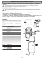
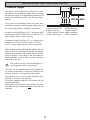
INSTRUCTION BOOKLET
COOKER HOOD
ZHC 590
Thank you for buying a Zanussi product.
To enable you to use your appliance effectively and safely, please read this instruction book carefully before using
the appliance and retain for future reference. If you require guidance in the use of the appliance or require further
information on Zanussi Products, please contact our Customer Services Department. For general enquiries concerning your Zanussi appliance or for further information, visit our website at http://www.zanussi.co.uk
Customer Services Department
Major Appliances
Zanussi
Addington Way
Luton
Bedfordshire
LU4 9QQ
Tel:
*Calls to this number may be recorded for training purposes.
08705 727 727*
To register ownership, please ensure you complete and return the guarantee card supplied with the appliance.
For the User
For the Installer
Technical Information
Important Safety Information
Electrical Connections
Electrical Requirements
Electrical Connection
Your Appliance
Operating Instructions
Installing the Cooker Hood
Cooker Hood Controls
To Operate
Recirculation
Extraction
Installation Requirements
Unpacking
Fitting the Wall Brackets
Fitting the Canopy Hood
Venting
Recirculation
Fitting the Chimney Stack
Maintenance and Cleaning
External Cleaning
Metal Grease Filters
Charcoal Filters
To Remove/Replace Charcoal Filter
Changing the Halogen Light
Something Not Working
Service and Spare Parts
Guarantee Conditions
Guide to use the instruction book
The following Symbols will be found in the text to guide you through the instruction book
Safety instructions
Step by step instructions
2
IMPORTANT SAFETY INFORMATION
These warnings are provided in the interests of your safety. Ensure that you understand them all before
installing or using this appliance. Your safety is of paramount importance. If you are unsure about any of the
meanings of these warnings contact the Customer Services Department.
Installation
Child Safety
• Any installation work must be undertaken by a qualified electrician or a competent person.
• This appliance is designed to be operated by adults.
Children should not be allowed to tamper with the
controls or play with the appliance.
• This hood must be installed in accordance with the
installation instructions and all measurements must
be adhered to.
During Use
• If the cooker hood is installed for use above a gas
appliance then the provision for ventilation must be
in accordance with the Gas Safety Codes of Practice
BS.6172, BS.5440 and BS.6891 (Natural Gas) and
BS.5482 (LP Gas) 1994, the Gas Safety (Installation
& Use) Regulations, the Building Regulations issued
by the Department of the Environment, the Building
standards (Scotland) (Consolidated) Regulations
issued by the Scottish Development Department.
• This product is for domestic use only.
• Never leave frying pans unattended during use as
over-heated fats and oils might catch fire.
• Never do flambé cooking under this cooker hood.
• Do not leave naked flames under the hood.
• The fan motor of this cooker hood incorporates a
cut-out device which will operate if the cooker hood
is installed below the minimum height recommended
under section ‘Clearance Height’, or if the motor becomes overheated. If the cut-out device is activated,
switch off the fan motor and allow the cooker hood to
cool. The cut-out device will reset itself when the fan
motor has cooled significantly.
• This cooker hood is designed to extract unpleasant
odours from the kitchen, it will not extract steam.
Maintenance and Service
• This appliance can be a hazard if the synthetic paper
and charcoal filters are not replaced as recommended.
• It is dangerous to alter the specifications or modify
this product in any way.
• Under no circumstances should you attempt to
repair the appliance yourself. Repairs carried out
by inexperienced persons may cause injury or more
serious malfunction. Refer to your local Zanussi Service Force Centre. Always insist on genuine spare
parts.
• When installed between adjoining wall cabinets the
wall cabinets must not overhang the hob.
• If the room where the hood is to be used contains
a fuel burning appliance such as a central heating
boiler then its flue must be of the room sealed or
balanced flue type.
• If other types of flue or appliances are fitted ensure
that there is an adequate supply of air to the room.
• The ducting system for this appliance must not be
connected to any existing ventilation system which is
being used for any other purpose.
• Do not install above a cooker with a high level grill.
3
YOUR APPLIANCE
4
OPERATING INSTRUCTIONS
The cooker hood is designed to extract unpleasant odours from the kitchen, it will not extract steam.
The appliance can be installed to recirculate or extract contaminated air.
Control Panel
The hood can be switched on pushing directly onto the requested speed without firstly having to select 0/1 button.
KEY
LED
L
0/1 Light
T1
0/1 Motor
FUNCTIONS
Turns lighting on and off.
on
First speed.
When pressed for about 1 seconds the
motor is switched off.
T2
Speed
on
Second speed.
T3
Speed
on
Third speed.
T4
Speed
Fixed
Max. speed
Flashing
Intensive speed.
Suitable for the strongest cooking vapours
and odours. The function becomes active
when the button is pushed for about 2
seconds. After 10 minutes of functioning
it turns off automatically. This function can
be interrupted by means of pressing any
of the buttons.
S1
Led
L
T1
Fixed
Indicates that the Metal grease filters
saturation alarm has been triggered, and
the filters need to be washed. The alarm is
triggered after 100 working hours. (Reset;
check the Maintenance-paragraph)
Flashing
indicates that the activated charcoal odour
filter saturation alarm has been triggered,
and the filter has to be replaced; the metal
grease filters must also be washed. The
activated charcoal odour filter is triggered
after 200 working hours. (Activation
and Reset; check the Maintenanceparagraph)
5
T2
T3
T4
S1
OPERATING INSTRUCTIONS
To Operate
Select the required fan speed and light if required.
Recirculation
In the recirculation mode the contaminated air enters
the cooker hood through the grease filters. The air is
cleaned by passing through the charcoal filters before
being passed back into the kitchen through the grilles in
either side of the chimney stack.
Extraction
In the extraction mode the contaminated air enters the
cooker hood passing through the grease filters and is
passed out through the ducting into the atmosphere.
To obtain the best performance when cooking it is advisable to switch the cooker hood on for a few minutes
before you start cooking and leave it running for about
15 minutes after finishing.
When used in the ducting mode the charcoal
filters are not required.
Never do flambé cooking under this cooker hood.
Never leave frying pans unattended during use,
as over-heated fats and oils can catch fire.
Do not leave naked flames under the cooker
hood.
Ensure heating areas on your hob are covered
with pots and pans when using the hob and
cooker hood simultaneously.
6
MAINTENANCE AND CLEANING
Before carrying out any maintenance or cleaning isolate the cooker hood from the mains
supply.
The cooker hood must be kept clean, as a build
up of grease or fat can be a fire hazard.
External Cleaning
Wipe the cooker hood frequently with warm
soapy water using a mild detergent.
Never use scouring pads or abrasive cleaners.
Never use excessive amounts of water when
cleaning particularly around the control panel.
Metal Grease Filters
The filters are washable and must be cleaned when the
Led S1 lights up or at least every 2 months of operation, or more frequently for particularly heavy usage.
Remove the metal grease
filters one at a time by:
• Open the lighting unit by pulling on the notch.
• Releasing the catches on the filters, the filters can
be removed.
The metal grease filters should be washed, by
hand, in mild soapy water or in a dishwasher. Allow
to dry completely before replacing.
Alarm signal reset
Switch off the lights and extractor motor.
Press Button T3 for at least 3 seconds, until
the leds start to flash.
7
MAINTENANCE AND CLEANING
Before carrying out any maintenance or cleaning isolate the cooker hood from the mains supply.
Charcoal Filters
In the recirculation mode the charcoal filters absorb smells and unwanted odours.
Enabling the alarm signal
•
•
•
•
•
•
In Recirculation version Hoods, the Filter saturation alarm can be enabled on installation or at a later date.
Turn the Lights and the suction Motor off.
Disconnect the Hood using the Main switch or the double-pole switch on the mains power supply.
Restore the connection by pressing and holding T1.
Release the button. All five LEDs are turned on
Within 3 seconds press T1 until LEDs T1 and T4 flash in confirmation:
• LED flashes twice - Activated charcoal filter saturation alarm ENABLED
• LED flashes once - Activated charcoal filter saturation alarm DISABLED
The filter is not washable and cannot be regenerated. It must be replaced when led S1 flashes or at least every
4 months. The alarm signal will only light up when the extractor motor is switched on.
To Remove/Replace the Charcoal Filters
• Open the lighting unit by pulling on the notch.
• Remove the metal grease filters
• Remove the saturated activated carbon filter by
releasing the fixing hooks
• Fit the new filter by hooking it into its seating
• Replace the metal grease filters.
This appliance can be a possible fire
hazard if the grease and charcoal filters
are not cleaned and replaced as recommended.
Alarm signal reset
• Switch off the lights and extractor motor.
• Press button T3 for at least 3 seconds, until the
leds start to flash.
Changing the halogen light
• Remove the halogen lamp from the lamp holder by
pulling gently.
• Replace the lamp with a new one of the same type,
making sure that you insert the two pins properly
into the housings on the lamp holder.
Replacement filters and halogen light can be obtained from your local Service Force Centre.
8
SOMETHING NOT WORKING
If, having followed these instructions carefully, your cooker hood fails to work properly please carry out
the following checks.
Symptom
Solution
The cooker hood will not start
• Check the hood is connected to the electricity
supply.
• Make sure the switch is in the ‘ON’ position.
The cooker hood is not working effectively
• The fan speed is set high enough for the task
• The grease filter is clean.
• The kitchen is adequately vented to allow the
entry of fresh air.
• If set up for recirculation, check that the charcoal
filter is still effective.
• If set up for extraction, check that the ducting and
outlets are not blocked.
The cooker hood has switched off during operation
• The safety cut-out device has been tripped.
• Tum off the hob and then wait for the device to
reset.
In-guarantee customers should ensure that the
above checks have been made as the engineer will
make a charge if the fault is not a mechanical or
electrical breakdown.
If after all these checks, the fault persists, contact your
local Service Force Centre, quoting the model and
serial number.
Please note that it will be necessary to provide proof of
purchase for any in-guarantee service calls.
SERVICE AND SPARE PARTS
If you require an engineer or spare parts contact your
local Service Force Centre by telephoning:
For general assistance with your appliance or for further
information on Zanussi products please contact our
Customer Services Department.
08705 929929
Customer Services Department
Major Appliances
Zanussi
Addington Way
Luton
Bedfordshire
LU4 9QQ
Tel: 08705 727 727 *
Your telephone call will be routed to your local Service
Force Centre. For the address of your local Service Force Centre and further information about Service Force,
please visit the website at www.serviceforce.co.uk
* calls to this number may be recorded for training
purposes.
9
GUARANTEE CONDITIONS
We Zanussi, undertake that if within twenty four months of the date of the purchase this Zanussi built-in appliance or
any part thereof is proved to be defective by reason only of faulty workmanship or materials, the company will, at our
option repair or replace the same FREE OF ANY CHARGE for labour, materials or carriage on condition that:
•
•
•
•
•
The appliance has been correctly installed and used only on the electrical supply stated on the rating plate.
The appliance has been used for normal domestic purposes only, and in accordance with the manufacturer’s
operating and maintenance instructions.
The appliance has not been serviced, maintained, repaired, taken apart or tampered with by any person not
authorised by us.
All service work under this guarantee must be undertaken by Zanussi Service Force Centre.
Any appliance or defective part replaced shall become the property of this company.
Home visits are made between 8.30am and 5.30pm Monday to Friday. Visits may be available outside these hours
in which case a premium will be charged.
EXCLUSIONS
This Guarantee does not cover:
• Damage or calls resulting from transportation, improper use or neglect, the replacement of any lilght bulbs or
removable parts of glass or plastic.
• Costs incurred for calls to put right appliances improperly installed or calls to appliances outside the United
Kingdom.
• Appliances found to be in use within a commercial environment, plus those which are the subject of rental agreements.
• Products of Zanussi manufacture which are not marked by Zanussi.
This guarantee is in addition to your statutory and legal rights.
ZANUSSI EUROPEAN GUARANTEE
If you should move to another country within Europe then your guarantee moves with you to your new home subject
to the following qualifications:
• The guarantee starts from the date you first purchased your product.
• The guarantee is for the same period and to the same extent for labour and parts as exists in the new country of
use for this brand or range of products.
• This guarantee relates to you and cannot be transferred to another user.
• Your new home is within the European Community (EC) or European Free Trade Area.
• The product is installed and used in accordance with our instructions and is only used domestically, i.e. a normal
household.
Before you move please contact your nearest Customer Care Centre, listed below, to give them details of
your new home. They will then ensure that the local Service Organisation is aware of your move and able to
look after you and your appliances.
France
Germany
Italy
Sweden
UK
Senlis
Nurnberg
Pordenone
Stockholm
Luton
+33 (0)3 44 62 22 22
+49 (0)911 323 2600
+39 (0)1678 47053
+46 (0)20 78 77 50
+44 (0)8705 727 727
10
INSTALLATION INSTRUCTIONS
It is dangerous to alter the specifications or attempt to modify this product in any way.
Technical Information
DIMENSIONS
HEIGHT OF CANOPY:
HEIGHT OF CHIMNEY:
WIDTH OF CANOPY :
DEPTH OF CANOPY:
ELECTRICAL SUPPLY:
935 mm
(UPPER SECTION) 290 mm
(LOWER SECTION) 935 mm
370 mm
370 mm
VOLTAGE:
POWER CONSUMPTION:
FAN MOTOR:
LAMPS : (4 x 20 W)
220-240 V 50Hz
410 W
330 W
80 W
Note: CE Marking certifies that this appliance complies with the requirements
laid down in EEC directive 89:336. (Electromagnetic compatibility) and
subsequent modifications and Low Voltage directive 72/23/E.
The symbol
on the product or on its packaging indicates that this product may not be treated as household waste. Instead it shall be handed
over to the applicable collection point for the recycling of electrical and electronic equipment. By ensuring this product is disposed of correctly,
you will help prevent potential negative consequences for the environment and human health, which could otherwise be caused by inappropriate
waste handling of this product. For more detailed information about recycling of this product, please contact your local city office, your household
waste disposal service or the shop where you purchased the product.
ELECTRICAL CONNECTIONS
THIS APPLIANCE MUST BE EARTHED
Electrical Requirements
This appliance is fitted with a 3 core mains cable and
must be permanently connected to the electricity supply
via a double-pole switch having 3mm minimum contact
gap on each pole. A Switched Fuse Connection Unit to
BS1363 Part 4, fitted with a 3 Amp fuse, is a recommended mains supply connection accessory to ensure
compliance with the Safety Requirements applicable to
fixed wiring instructions.
Any permanent electrical installation must comply with
the latest I.E.E. Regulations and local Electricity Board
regulations. For your own safety this should be undertaken by a qualified electrician e.g. your local Electricity
Board, or a contractor who is on the roll of the National
Inspection Council for Electrical Installation Contracting
(NICEIC).
This appliance conforms to BS 800: 1988 and EEC
Directive No. 78 308 regarding suppression of radio and
television interference.
Electrical Connection
Before connecting to the mains supply ensure that the
mains voltage corresponds to the voltage on the rating
plate inside the cooker hood.
11
INSTALLING THE COOKER HOOD
Please ensure that when the appliance is installed it is easily accessible to an engineer in the event of a
breakdown.
All installations must comply with the local authorities requirements for the discharge of exhaust air.
Incorrect installation may affect the safety of this cooker hood.
Installation Requirements
Before installation check the wall to which the cooker hood is to be fitted for electric cables, water pipes or
gas.
This cooker hood is designed to be fixed to any orizontal surface over a cooking area, and can be used in the
extraction (ducted to the outside) or recirculation mode.
The installation work must be undertaken by a qualified and competent person.
The manufacturer disclaims any responsibility for damage due to incorrect installation of the cooker hood or if the
hood is not installed in compliance with relevant regulations controlling this type of installation.
14.1
Unpacking
Before unpacking the cooker hood position the carton
with the arrows pointing upwards as illustrated on the
carton.
The cooker hood is made up of the following components:
Ref. Q.ty
1
1
2
7.1
1
1
7.1a
7.1b
8
9
9a
14.1
14.2
15
25
1
1
1
1
1
1
1
1
2
Ref. Q.ty
12f 4
21
1
Q.ty
1
14.2
21
15
Product Components
Hood Body, complete with: Controls, Light,
Blower, Filters
Upper Chimney
Telescopic frame complete with extractor,
consisting of:
Upper frame
Lower frame
Air Outlet Grill
Reducer Flange ø 150-120 mm
Ø120-125mm collar
Air Outlet Connection Extension
Air Outlet Extension
Air Outlet Connection
Pipe clamps
7.1a
14
25
9a
7.1
9
7.1b
2
Installation Components
Screws M6 x 15
Drilling template
8
Documentation
Instruction Manual
1
12f
12
INSTALLING THE COOKER HOOD
Clearance Height
The cooker hood is designed to be fitted over a cooking appliance at the clearance heights stated, providing
the maximum output of the appliance beneath does not
exceed the maximums quoted in the Technical Specifications.
If the output of the appliance below the cooker hood
exceeds the maximum outputs quoted, please refer to
the cooker manufacturer’s installation instructions.
Hob
A: Built-in Electric Hob:
B: Built-in Gas hob:
C: Slot-in Electric Cooker:
D: Slot-in Gas Cooker:
A clearance height of 650mm (25 1/2 ”) is required when
installed above a built-in electric hob, or 700mm (27 1/2”)
when installed above a built-in gas hob.
A clearance height of 685mm (27”) is required when
installed above a slot-in electric cooker, or 787mm
(30 1/2 ”) when installed above a slot-in gas cooker.
When installed between adjoining wall cabinets, the wall
cabinets must not overhang the hob and the distance
between the underside of the cabinet and the worktop
must be 450mm. If the height of the wall cabinet is
less than 450mm, a gap of 50mm must be maintained
either side of the hob.
This cooker hood must not be installed above a
cooking appliance with a high level grill.
The hood can be installed above these heights but
for optimum performance it should be installed at the
distances quoted for the appropriate heat source.
This appliance can be used in either extraction mode
(ducting) or recycling mode (filtering).
The hood is supplied suitable for recirculation with the
charcoal filters fitted.
When used in the extraction mode (ducting) the charcoal filters are not required and must be removed and
destroyed.
13
650mm clearance
700mm clearance
685mm clearance
787mm clearance
INSTALLING THE COOKER HOOD
Drilling the Ceiling/Support
Shelf
• Use a plumb line to mark the centre of the hob on
the ceiling/support shelf.
• Place the drilling template 21 provided on the ceiling/
support shelf, making sure that the template is in the
correct position by lining up the axes of the template
with those of the hob.
• Mark the centres of the holes in the template.
• Drill the holes at the points marked:
• For concrete ceilings, drill for plugs appropriate to
the screw size.
• For hollow brick ceilings with wall thickness of 20
mm: drill ø 10 mm (immediately insert the Dowels
not provided).
• For wooden beam ceilings, drill according to the
wood screws used.
• For wooden shelf, drill ø 7 mm.
• For the power supply cable feed, drill ø 10 mm.
• For the air outlet (Ducted Version), drill according
to the diameter of the external air exhaust duct
connection.
• Insert two screws of the following type, crossing them
and leaving 4-5 mm from the ceiling:
• For concrete ceilings, use the appropriate plugs
for the screw size (not provided).
• For Cavity ceiling with inner space, with wall thickness of approx. 20 mm, Screws not provided.
• For wooden beam ceilings, use 4 wood screws
(not provided).
• For wooden shelf, use 4 screws with washers and
nuts (not provided)
Fixing the Frame
A
• Unfasten the two screws fastening the upper chimney
stack 2.1 to the frame, and remove the chimney from
the upper stack.
If you wish to adjust the height of the frame, proceed
as follows:
• Unfasten the four safety screws located at the top
in the frame separation area. (A)
• Unfasten the eight metric screws joining the two
columns, located at the sides of the frame. (B)
• Adjust the frame to the height required, then replace
all the screws removed as above.
• To guarantee greater stability in the frame, replace
the four safety screws in the last hole available.
• Insert the upper chimney stack from above, and leave
it running free on the frame.
B
14
INSTALLING THE COOKER HOOD
• Lift the frame up, making sure that the index over
the frame plate is turned backwards.
• Fit the frame slots onto the two screws inserted in the
ceiling as above, and turn until reaching the centre
of the adjustment slot.
• Tighten the two screws and fasten the other two
screws provided; before locking the screws completely, it is possible to adjust the frame by turning it,
making sure that the screws do not come out of their
housing in the adjustment slot.
1
2
• The Frame must be securely fastened so as to
support both the weight of the Hood and the stress
caused by occasional axial pressure against the
fitted Appliance. After fixing, make sure that the
base is stable even when the Frame is subjected
to lateral stress.
• If the Ceiling is not strong enough in the area
where the hood is to be fixed, the Installer must
strengthen the area using suitable plates and
counterplates anchored to resistant structures.
Extraction
The cooker hood is more effective when used in the
extraction mode (ducted to the outside).
Venting kits may be purchased through your retailer
or DIY store, and must be ducted to an outside vent
of Ø125mm (5”) or Ø150mm (6”).
For the best performance use the shortest possible duct
run and the minimum number of bends.
Where flexible ducting is fitted it should not be turned
through very tight bends as this may impair the performance of the hood.
It is recommended a maximum length of 3 metres
with one bend, to be installed, to be reduced metre
for each 90o bend.
If a distance is greater than 3 metres the efficiency of
the hood could be impaired.
The ducting used must be manufactured from fire
retardent material conforming to the relevant British
Standard or DIN 4102-B1.
When the cooker hood is ducted to the outside the
charcoal filter must be removed.
15
1
2
INSTALLING THE COOKER HOOD
Ducting Connection
Connect the ducting chosen to:
• the Ø150mm ducting spigot on top of the motor
housing, or the Ø150-120mm ducting spigot item 9
and secure using the jubilee clips item 25.
9 + 9a
• A Ø120-125mm collar item 9a is provided to fit over
the Ø120mm ducting spigot when 125mm ducting is
fitted.
ø 150
ø 125
If the room where the cooker hood is to be used
contains a fuel burning appliance such as a central
heating boiler, then its flue must be of the room
sealed or balanced flue type.
If other types of flue or appliances are fitted sure
that there is an adequate supply of air to the
room.
The cooker ducting (extraction mode) must never
be connected to central heating flues, radiators or
water heaters etc.
Recirculation
The cooker hood is supplied specified for use in the
recirculation mode, with the charcoal filter fitted.
In the recirculation mode contaminated air is passed
through the charcoal filter to be purified and recirculated
into the kitchen through the grille outlets on either side
of the chimney.
Recirculation Connection
• Insert reducer flange 9 on the extractor outlet.
• Push fit connector 15 onto the reducer flange.
• Insert extension piece 14.2 sideways into connector
15 making sure that the outlet corresponds with the
mouth of the chimney
15
14.2
9
16
INSTALLING THE COOKER HOOD
Chimney Stack
The chimney consists of two sections.
The lower chimney measures (with the Hood body and
recirculation grilles) 935 mm and the upper chimney
measures 290 mm. The overall installed measurement
is min. 935 - max 1215 mm.
Fitting the Upper Chimney and
the Hood Body
• Position the upper chimney stack and fix the top of
it to the frame using 2 of the screws removed as
above.
• Open the lighting unit by pulling on the notch, disconnect it from the hood canopy by sliding out the fixing
pin.
• Remove the activated charcoal filters, if fitted.
• In order to fix the hood body to the frame insert the
4 screws 12f in their seats. It is necessary to leave
at least 4-5 mm gap between the screw heads and
the frame plate.
• Hook the hood canopy to the frame and turn it to
the left until it reaches the stop, then lock the screws
immediately to prevent the hood canopy from falling
out accidentally.
• Make sure that the outlet of the extension piece 14.1
is horizontally and vertically aligned with the chimney
outlet.
• If this is not the case, remove the lower Chimney
Stack and adjust the position of connector 15; replace
the elements as described above.
• Insert Connector Extension 14.1 sideways into Extension 14.2.
• Fit the directional grill 8 into the housing provided.
Also make sure that it is properly fitted into connector
14.1.
14.1
1
2
Electrical Connection
• Ensure that the supply cable connector is properly
inserted into the Suction device socket
• Hook up the Commands connector Cmd.
• Hook up the Spotlights connector Lux to the socket
provided behind the lighting unit cover.
Lux
• For the recirculation version, fit the activated carbon
odour filter.
• Replace the grease filters.
• Replace the lighting unit.
Cmd
17
Service and Spare Parts
In the event of your appliance requiring service, or if you wish
to purchase spare parts please contact your local Service
Force Centre by telephoning:
08705 929929
Your telephone call will be automatically routed to the Service
Force centre covering your post code area.
For the address of your local Service Force Centre and further
information about Service Force, please visit the website at
www.serviceforce.co.uk
Before calling out an engineer, please ensure you read the
details under the heading Something not working.
When you contact the Service Force Centre you will need to
give the following details:
1. Your name, address and post code
2. Your telephone number
3. Clear and concise details of the fault
4. The model and serial number (found on the rating plate)
5. The purchase date
Please note that a valid purchase receipt or guarantee
documentation is required for in-guarantee service calls.
For Customer Service in Ireland please contact us at the
address below:
Zanussi
Electrolux Group (Irl) Ltd
Long Mile Road
Dublin 12
Republic of Ireland
Tel: + 353 (0)1 4090751
Email: [email protected]
Customer Care
Department
For general enquiries concerning your Zanussi appliance or for
further information on Zanussi products please contact our
Customer Care Department by letter or telephone at the
address below or visit our website at www.zanussi.co.uk
Customer Services Department
Major Appliances
Zanussi
Addington Way
Luton
Bedfordshire
LU4 9QQ
Tel: 08705 727 727 *
* calls to this number may be recorded for training
purposes.
18
Dir. 89/336/CEE
73/23/CEE
93/68/CEE
© Electrolux plc 2002
436002645_04 - 060303