1
GZKDJRRJDGHZ2[JZFJR
R-410A
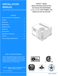
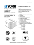
AFFINITY SERIES
DNX024-048
ISO 9001
Certified Quality
2-4 Ton
Management System
TABLE OF CONTENTS
General . . . . . . . . . . . . . . . . . . . . . . . . . . . . . . . . . . . . . . . . . . 1
Installation . . . . . . . . . . . . . . . . . . . . . . . . . . . . . . . . . . . . . . . . 3
Limitations . . . . . . . . . . . . . . . . . . . . . . . . . . . . . . . . . . . . 3
Location. . . . . . . . . . . . . . . . . . . . . . . . . . . . . . . . . . . . . . . . 5
Rigging And Handling . . . . . . . . . . . . . . . . . . . . . . . . . . . . . 5
Ductwork . . . . . . . . . . . . . . . . . . . . . . . . . . . . . . . . . . . . . . . 9
Roof Curb . . . . . . . . . . . . . . . . . . . . . . . . . . . . . . . . . . . . . . 9
Filters . . . . . . . . . . . . . . . . . . . . . . . . . . . . . . . . . . . . . . . . . 9
Condensate Drain . . . . . . . . . . . . . . . . . . . . . . . . . . . . . . . . 9
Service Access . . . . . . . . . . . . . . . . . . . . . . . . . . . . . . . . . 10
Thermostat . . . . . . . . . . . . . . . . . . . . . . . . . . . . . . . . . . . . 10
Power And Control Wiring. . . . . . . . . . . . . . . . . . . . . . . . . 10
Compressors. . . . . . . . . . . . . . . . . . . . . . . . . . . . . . . . . . . 15
Phasing . . . . . . . . . . . . . . . . . . . . . . . . . . . . . . . . . . . . . . .
Gas Heat . . . . . . . . . . . . . . . . . . . . . . . . . . . . . . . . . . . . . .
Flue Vent Hood . . . . . . . . . . . . . . . . . . . . . . . . . . . . . . . . .
Airflow Performance . . . . . . . . . . . . . . . . . . . . . . . . . . . . . . .
Blower Speed Selection . . . . . . . . . . . . . . . . . . . . . . . . . .
Operation . . . . . . . . . . . . . . . . . . . . . . . . . . . . . . . . . . . . . . .
Heating Sequence Of Operation . . . . . . . . . . . . . . . . . . . .
Cooling Sequence Of Operations . . . . . . . . . . . . . . . . . . .
Start-Up . . . . . . . . . . . . . . . . . . . . . . . . . . . . . . . . . . . . . . . . .
Adjustment of Temperature Rise . . . . . . . . . . . . . . . . . . .
Checking Gas Heat Input . . . . . . . . . . . . . . . . . . . . . . . . . . .
Natural Gas . . . . . . . . . . . . . . . . . . . . . . . . . . . . . . . . . . . .
Typical Wiring Diagrams . . . . . . . . . . . . . . . . . . . . . . . . . . . .
15
15
16
18
21
22
22
24
25
27
27
27
28
LIST OF TABLES
1
2
3
4
5
6
7
8
9
10
Unit Limitations . . . . . . . . . . . . . . . . . . . . . . . . . . . . . . . . . 4
Weights and Dimensions . . . . . . . . . . . . . . . . . . . . . . . . . 6
Unit Accessory Weights . . . . . . . . . . . . . . . . . . . . . . . . . . 6
Unit Dimensions . . . . . . . . . . . . . . . . . . . . . . . . . . . . . . . . 7
Unit Clearances . . . . . . . . . . . . . . . . . . . . . . . . . . . . . . . . 7
Electrical Data . . . . . . . . . . . . . . . . . . . . . . . . . . . . . . . . . 12
Natural Gas Pipe Sizing Chart . . . . . . . . . . . . . . . . . . . . 16
Propane (LP) Gas Pipe Sizing Chart . . . . . . . . . . . . . . . 16
Natural Gas Application Data-Single Stage . . . . . . . . . . 17
Natural Gas Application Data-Two Stage . . . . . . . . . . . . 17
11
12
13
14
15
16
17
18
19
Propane (LP) Gas Application Data-Single Stage . . . . .
Propane (LP) Gas Application Data-Two Stage . . . . . . .
Side Duct Application . . . . . . . . . . . . . . . . . . . . . . . . . . .
Bottom Duct Application . . . . . . . . . . . . . . . . . . . . . . . . .
Additional Static Resistance . . . . . . . . . . . . . . . . . . . . . .
Indoor Blower Specifications . . . . . . . . . . . . . . . . . . . . . .
Delay Profile . . . . . . . . . . . . . . . . . . . . . . . . . . . . . . . . . .
Ignition Control Board FLASH CODES . . . . . . . . . . . . . .
Gas Rate Cubic Feet Per Hour . . . . . . . . . . . . . . . . . . . .
17
17
18
19
21
21
22
24
27
LIST OF FIGURES
1
2
3
4
5
6
7
Component Location . . . . . . . . . . . . . . . . . . . . . . . . . . . . 4
Unit 4 Point Load Weight . . . . . . . . . . . . . . . . . . . . . . . . . 6
Unit Dimensions . . . . . . . . . . . . . . . . . . . . . . . . . . . . . . . . 7
Dimensions Front and Bottom . . . . . . . . . . . . . . . . . . . . . 8
Dimensions Back and Bottom . . . . . . . . . . . . . . . . . . . . . 8
Roof Curb . . . . . . . . . . . . . . . . . . . . . . . . . . . . . . . . . . . . . 9
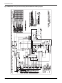
Typical Field Control Wiring Diagram Single Stage
Thermostat - Single Stage Gas Heat . . . . . . . . . . . . . . . 10
8 Typical Field Control Wiring Diagram Single Stage
Thermostat - Two Stage Gas Heat . . . . . . . . . . . . . . . . 11
9 Typical Field Control Wiring Diagram Two Stage
Thermostat - Single Stage Gas Heat . . . . . . . . . . . . . . . 11
10 Typical Field Control Wiring Diagram Two Stage
Thermostat - Two Stage Gas Heat . . . . . . . . . . . . . . . .
11 Typical Field Power Wiring Diagram . . . . . . . . . . . . . . .
12 External Supply Connection External Shut-Off . . . . . . .
13 Flue Vent Outlet Air Hood . . . . . . . . . . . . . . . . . . . . . . .
14 Control Board Speed Tap Location . . . . . . . . . . . . . . . .
15 Single Stage Gas Valve Front . . . . . . . . . . . . . . . . . . . .
16 Two Stage Gas Valve Front . . . . . . . . . . . . . . . . . . . . . .
17 Single Stage Gas Valve Rear . . . . . . . . . . . . . . . . . . . .
18 Two Stage Gas Valve Rear . . . . . . . . . . . . . . . . . . . . . .
19 Proper Flame Adjustment . . . . . . . . . . . . . . . . . . . . . . .
20 R-410A Quick Reference Guide . . . . . . . . . . . . . . . . . .
12
12
15
16
22
25
26
26
26
26
36
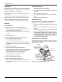
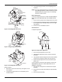
General
Safety Considerations
YORK® Affinity Model DNX units are cooling/heating air
conditioners designed for outdoor installation. Only gas piping,
electric power and duct connections are required at the point of
installation.
This is a safety alert symbol . When you see this symbol on
labels or in manuals, be alert to the potential for personal injury.
The single or two stage gas-fired heaters have spark to pilot
ignition. The tubular heat exchangers are aluminized steel.
DANGER indicates an imminently hazardous situation, which,
if not avoided, will result in death or serious injury.
The refrigerant system is fully charged with R-410A Refrigerant,
and is tested and factory sealed.
WARNING indicates a potentially hazardous situation, which,
if not avoided, could result in death or serious injury.
Understand and pay particular attention the signal words
DANGER, WARNING or CAUTION.
CAUTION indicates a potentially hazardous situation, which, if
not avoided may result in minor or moderate injury. It is also
used to alert against unsafe practices and hazards involving
only property damage.
279550-YIM-A-0207
279550-YIM-A-0207
Improper installation may create a condition where the
operation of the product could cause personal injury or
property damage. Improper installation, adjustment,
alteration, service or maintenance can cause injury or
property damage. Refer to this manual for assistance or
for additional information, consult a qualified contractor,
installer or service agency.
Due to system pressure, moving parts, and electrical
components, installation and servicing of air conditioning
equipment can be hazardous. Only qualified, trained service
personnel should install, repair, or service this equipment.
Untrained personnel can perform basic maintenance functions
of cleaning coils and filters and replacing filters.
Observe all precautions in the literature, labels, and tags
accompanying the equipment whenever working on air
conditioning equipment. Be sure to follow all other applicable
safety precautions and codes including ANSI Z223.1 or CSAB149.1- latest edition.
Wear safety glasses and work gloves. Use quenching cloth and
have a fire extinguisher available during brazing operations.
This product must be installed in strict compliance with
the installation instructions and any applicable local,
state and national codes including, but not limited to
building, electrical, and mechanical codes.
Inspection
As soon as a unit is received, it should be inspected for possible
damage during transit. If damage is evident, the extent of the
damage should be noted on the carrier’s freight bill. A separate
request for inspection by the carrier’s agent should be made in
writing.
Before performing service or maintenance operations on
unit, turn off main power switch to unit. Electrical shock
could cause personal injury. Improper installation,
adjustment, alteration, service or maintenance can
cause injury or property damage. Refer to this manual.
For assistance or additional information consult a
qualified installer, service agency or the gas supplier.
This product must be installed in strict compliance with
the enclosed installation instructions and any applicable
local, state and national codes including, but not limited
to, building, electrical, and mechanical codes.
The furnace and its individual shut-off valve must be
disconnected from the gas supply piping system during
any pressure testing at pressures in excess of 1/2 PSIG.
This system uses R-410A Refrigerant which operates at
higher pressures than R-22. No other refrigerant may be
used in this system. Gage sets, hoses, refrigerant
containers and recovery systems must be designed to
handle R-410A. If you are unsure, consult the equipment
manufacturer. Failure to use R-410A compatible servicing
equipment may result in property damage or injury.
Pressures greater than 1/2 PSIG will cause gas valve
damage resulting in a hazardous condition. If it is
subjected to a pressure greater than 1/2 PSIG, the gas
valve must be replaced.
The furnace must be isolated from the gas supply piping
system by closing its individual manual shut-off valve
during any pressure testing of the gas supply piping
system at test pressures equal to or less than 1/2 PSIG
Reference
If the information in this manual is not followed exactly, a
fire or explosion may result causing property damage,
personal injury or loss of life.
Do not store or use gasoline or other flammable vapors
and liquids in the vicinity of this or any other appliance.
WHAT TO DO IF YOU SMELL GAS:
a. Do not try to light any appliance.
b. Do not touch any electrical switch; do not use any
phone in your building.
c. Immediately call your gas supplier from a neighbor’s
phone. Follow the gas supplier’s instructions.
d. If you cannot reach your gas supplier, call the fire
department.
Installation and service must be performed by a qualified
installer, service agency or the gas supplier.
2
Additional information is available in the following reference
forms:
• Technical Guide - DNX024-048, 291625
• General Installation - DNX024-048, 279550
Renewal Parts
Contact your local York® parts distribution center for authorized
replacement parts.
Approvals
Design certified by CSA as follows:
1.
For use as a cooling only unit, cooling unit with
supplemental electric heat or a forced air furnace.
2.
For outdoor installation only.
Unitary Products Group
279550-YIM-A-0207
3.
For installation on combustible material and may be
installed directly on combustible flooring or, in the U.S., on
wood flooring or Class A, Class B or Class C roof covering
materials.
4.
For use with natural gas (convertible to LP with kit).
Improper installation may create a condition where the
operation of the product could cause personal injury or
property damage.
This product must be installed in strict compliance with
the enclosed installation instructions and any applicable
local, state, and national codes including, but not limited
to, building, electrical, and mechanical codes.
This system uses R-410A Refrigerant which operates at
higher pressures than R-22. No other refrigerant may be
used in this system.
Nomenclature
D 1
NX 036 N 036
06
Product Category
Voltage Code
D = Single Package Air Conditioner
06 = 208/230-1-60
25 = 208/230-3-60
46 = 460-3-60
Product Generation
1 = 1st Generation
2 = 2nd Generation
Product Identifier
NX = R-410A 15 SEER
Gas Heat/Electric
Factory Installed Gas Heat
N = Single Stage
D = Two Stage
Nominal Cooling Capacity (MBH)
024 = 24,000 BTUH
036 = 36,000 BTUH
048 = 48,000 BTUH
Nominal Gas Heating Output Capacity
(Nominal Low Gas Heat Output Capacity)
036 = 36,000 BTUH
056 = 56,000 BTUH (36,400 BTUH)
065 = 65,000 BTUH
072 = 72,000 BTUH (46,800 BTUH)
090 = 90,000 BTUH (56,160 BTUH)
110 = 110,000 BTUH (70,200 BTUH)
Installation
Installation Safety Information
FIRE OR EXPLOSION HAZARD
Read these instructions before continuing this appliance
installation. This is an outdoor combination heating and cooling
unit. The installer must assure that these instructions are made
available to the consumer and with instructions to retain them
for future reference.
1.
Refer to the unit rating plate for the approved type of gas
for this product.
2.
Install this unit only in a location and position as specified
on Page 5 of these instructions.
3.
Never test for gas leaks with an open flame. Use
commercially available soap solution made specifically for
the detection of leaks when checking all connections, as
specified on Pages 3 and 16 of these instructions.
4.
5.
Always install furnace to operate within the furnace's
intended temperature-rise range with the duct system and
within the allowable external static pressure range, as
specified on the unit name/rating plate, specified on
Page 17 of these instructions.
This equipment is not to be used for temporary heating of
buildings or structures under construction.
Unitary Products Group
Failure to follow the safety warning exactly could result
in serious injury, death or property damage.
Never test for gas leaks with an open flame. use a
commercially available soap solution made specifically
for the detection of leaks to check all connections. A fire
or explosion may result causing property damage,
personal injury or loss of life.
Limitations
These units must be installed in accordance with the following:
In U.S.A.:
1.
National Electrical Code, ANSI/NFPA No. 70 - Latest Edition
2.
National Fuel Gas Code, ANSI Z223.1 - Latest Edition
3.
Gas-Fired Central Furnace Standard, ANSI Z21.47a. Latest Edition
4.
Local building codes, and
5.
Local gas utility requirements
3
279550-YIM-A-0207
In Canada:
1.
If components are to be added to a unit to meet local codes,
they are to be installed at the dealer’s and/or customer’s
expense.
Canadian Electrical Code, CSA C22.1
2.
Installation Codes, CSA - B149.1.
3.
Local plumbing and waste water codes, and
4.
Other applicable local codes.
Size of unit for proposed installation should be based on heat
loss/heat gain calculation made according to the methods of Air
Conditioning Contractors of America (ACCA).
Refer to unit application data found in this document.
After installation, gas fired units must be adjusted to obtain a
temperature rise within the range specified on the unit rating plate.
This furnace is not to be used for temporary heating of buildings
or structures under construction.
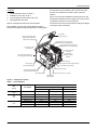
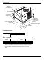
Direct Drive
Condenser Fan Motor
Blow-Through Design With
Reliable Aluminized Steel
Tubular Heat Exchangers
Highly Efficient Enhanced Copper
Tube/Aluminum Fin Evaporator Coil
Highly Efficient Enhanced Copper
Tube/Aluminum Fin Condenser Coil
Long Lasting Powder
Paint Finish
Decorative Protective
Coil Guard
High Efficiency
Compressor Rigidly
Mounted
Rear and Bottom Return Air
and Supply Airduct Openings
Pilot Assembly
High Grade Aluminized In-Shot Burners
Heavy Gauge
Removable Base Rails
Low Voltage Terminal Block
Self-Diagnostic Controls
Direct Drive Blower Motor With
Slide-Out Blower Assembly
Power Draft Motor
Automatic Gas Valve (1/2" - 14 NPTI)
High Voltage
Terminal Block
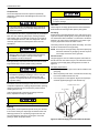
Figure 1: Component Location
Table 1:
Unit Limitations
Unit Voltage
024
(2.0)
036
(3.0)
048
(4.0)
4
Unit Limitations
Size
(Tons)
Applied Voltage
Outdoor DB Temp
Min
Max
Max (°F)
208/230-1-60
187
252
115
208/230-1-60
187
252
115
208/230-3-60
187
252
115
460-3-60
432
504
115
208/230-1-60
187
252
115
208/230-3-60
187
252
115
460-3-60
432
504
115
Unitary Products Group
279550-YIM-A-0207
Location
codes. Refer to Table 5 for clearances required for combustible
construction, servicing, and proper unit operation.
Use the following guidelines to select a suitable location for
these units:
1.
Unit is designed for outdoor installation only.
2.
Condenser coils must have an unlimited supply of air.
Where a choice of location is possible, position the unit on
either north or east side of building.
3.
Suitable for mounting on roof curb.
4.
For ground level installation, a level pad or slab should be
used. The thickness and size of the pad or slab used
should meet local codes and unit weight. Do not tie the
slab to the building foundation.
5.
Roof structures must be able to support the weight of the
unit and its options/accessories. Unit must be installed on a
solid, level roof curb or appropriate angle iron frame.
6.
Maintain level tolerance to 1/8” across the entire width and
length of unit.
Excessive exposure of this furnace to contaminated
combustion air may result in equipment damage or
personal injury. Typical contaminates include:
permanent wave solution, chlorinated waxes and
cleaners, chlorine based swimming pool chemicals,
water softening chemicals, carbon tetrachloride,
Halogen type refrigerants, cleaning solvents (e.g.
perchloroethylene), printing inks, paint removers,
varnishes, hydrochloric acid, cements and glues,
antistatic fabric softeners for clothes dryers, masonry
acid washing materials.
Do not permit overhanging structures or shrubs to
obstruct condenser air discharge outlet, combustion air
inlet or vent outlets.
Rigging And Handling
Exercise care when moving the unit. Do not remove any
packaging until the unit is near the place of installation. Rig the
unit by attaching chain or cable slings to the lifting holes
provided in the base rails. Spreader bars, whose length
exceeds the largest dimension across the unit, MUST be used
across the top of the unit.
If a unit is to be installed on a roof curb other than a
York® roof curb, gasketing must be applied to all
surfaces that come in contact with the unit underside.
Before lifting, make sure the unit weight is distributed
equally on the rigging cables so it will lift evenly.
Units may be moved or lifted with a forklift. Slotted openings in
the base rails are provided for this purpose.
Clearances
All units require particular clearances for proper operation and
service. Installer must make provisions for adequate
combustion and ventilation air in accordance with section 5.3 of
Air for Combustion and Ventilation of the National Fuel Gas
Code, ANSI Z223.1 – Latest Edition (in U.S.A.), or Sections 7.2,
7.3, or 7.4 of Gas Installation Codes, CSA-B149.1 (in Canada) Latest Edition, and/or applicable provisions of the local building
Unitary Products Group
All panels must be secured in place when the unit is
lifted.
The condenser coils should be protected from rigging
cable damage with plywood or other suitable material.
5
279550-YIM-A-0207
'
&(17(52)
*5$9,7<
)5217
2)
81,7
&
$
%
;
<
Figure 2: Unit 4 Point Load Weight
Table 2:
Weights and Dimensions
Weight (lbs.)
Center of Gravity
Size
(Tons) Shipping Operating
X
Y
024
445
440
20
24.5
(2.0)
036
445
440
20
24.25
(3.0)
048
505
500
20
24
(4.0)
Table 3:
6
4 Point Load Location (lbs.)
A
B
C
D
127
93
93
127
126
91
93
129
142
102
107
149
Unit Accessory Weights
Unit Accessory
Model
Add Economizer
All
Weight (lbs.)
Shipping
Operating
45
40
Unitary Products Group
279550-YIM-A-0207
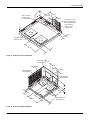
9(17$,5287/(7+22'
*$66833/<
',$0(7(5+2/(
137,&211(&7,21
%/2:(56(59,&($&&(66
&203$570(173$1(/
&21'(16(5&2,/
81,7&21'(16$7(
&211(&7,21137,
75$35(&200(1'('
$
%
+,*+92/7$*(
&211',$
.12&.287
5()5,*(5$17
&211(&7,216
&20%867,21$,5
,1/(7/289(56
*$66833/<
',$.12&.287
137,&211(&7,21
/2:92/7$*(
&211',$
.12&.287[+2/(
)5217
29(5$//
29(5$//
*$6(/(&75,&&21752/
6(59,&($&&(66
&203$570(173$1(/
Figure 3: Unit Dimensions
Table 4:
Unit Dimensions
Unit Size
Dimensions
“A”
“B”
024
33-1/2
18-1/4
036, 048
41-1/2
23-1/8
Direction
Distance
(in.)
Direction
Table 5:
Unit Clearances1 2
Distance
(in.)
Top3
36
Right
12
Front
36
Left
24
Rear
0
Bottom4
0
1. A 1" clearance must be provided between any combustible material and the supply air duct work.
2. The products of combustion must not be allowed to accumulate within a confined space and recirculate.
3. Units must be installed outdoors. Over hanging structure or shrubs should not obscure condenser air
discharge outlet.
4. Units may be installed on combustable floors made from wood or class A, B or C roof covering
materials.
Unitary Products Group
7
279550-YIM-A-0207
+,*+92/7$*(
&211
',$.12&.287
)5217
*$66833/<
',$.12&.287
137,&211(&7,21
/2:92/7$*(
&211',$
.12&.287
&21'(16$7('
5$,1137,
Figure 4: Dimensions Front and Bottom
6,'(6833/<
$,523(1,1*
&21'(16(5
&2,/
%$&.
%277206833/<
$,523(1,1*
6,'(5(7851
$,523(1,1*
%277205(7851
$,523(1,1*
Figure 5: Dimensions Back and Bottom
8
Unitary Products Group
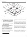
279550-YIM-A-0207
5(&200(1'('
'8&76,=(
[
23(1,1*)25
5(7851$,5'8&7
23(1,1*)25
6833/<$,5'8&7
5(&200(1'('
'8&76,=(
[
Figure 6: Roof Curb1
Ductwork
Roof Curb
These units are adaptable to downflow use as well as rear
supply and return air duct openings. To convert to downflow,
use the following steps:
On applications when a roof curb is used, the unit must be
positioned on the curb so the front of the unit is tight against the
curb.
1.
2.
3.
Remove the duct covers found in the bottom return and
supply air duct openings. There are four (4) screws
securing each duct cover (save these screws to use in
Step 2).
Install the duct covers (removed in step one) to the rear
supply and return air duct openings. Secure with the four
(4) screws used in step one.
Seal duct covers with silicone caulk.
Duct work should be designed and sized according to the
methods of the Air Conditioning Contractors of America
(ACCA), as set forth in their Manual D.
Filters
Single phase units are shipped without a filter or filter racks. It is
the responsibility of the installer to secure a filter in the return air
ductwork or install a Filter/Frame Kit (1FF0110).
A filter rack and high velocity filters are standard on three phase
units.
Filters must always be used and must be kept clean. When
filters become dirt laden, insufficient air will be delivered by the
blower, decreasing your units efficiency and increasing
operating costs and wear-and-tear on the unit and controls.
A closed return duct system shall be used. This shall not
preclude use of economizers or ventilation air intake. Flexible
joints may be used in the supply and return duct work to
minimize the transmission of noise.
Filters should be checked monthly; this is especially important
since this unit is used for both heating and cooling.
NOTE: Be sure to note supply and return openings.
A condensate trap is recommended to be installed in the
condensate drain. The plumbing must conform to local codes.
Refer to Figures 4 and 5 for information concerning rear and
bottom supply and return air duct openings.
Condensate Drain
Use a sealing compound on male pipe threads. Install the
condensate drain line (3/4” NPTF) to spill into an open drain.
1. 8” Roof Curb also available.
Unitary Products Group
9
279550-YIM-A-0207
Service Access
Thermostat
Access to all serviceable components is provided at the
following locations:
The room thermostat should be located on an inside wall
approximately 56" above the floor where it will not be subject to
drafts, sun exposure or heat from electrical fixtures or
appliances. Follow manufacturer's instructions enclosed with
the thermostat for general installation procedure. Color coded
insulated wires (minimum #18 AWG) should be used to connect
thermostat to unit. See Figures 7 thru 10.
• Blower compartment access panel
• Gas control/electrical access panel
• Refrigerant connections
Refer to Figure 3 for location of these access locations and
minimum clearances in Table 5.
Power And Control Wiring
Field wiring to the unit must conform to provisions of the current
N.E.C. ANSI/NFPA No. 70 or C.E.C. and/or local ordinances.
The unit must be electrically grounded in accordance with local
codes or, in their absence, with the N.E.C./C.E.C. Voltage
tolerances which must be maintained at the compressor
terminals during starting and running conditions are indicated
on the unit Rating Plate and Table 6.
This system uses R-410A Refrigerant which operates at
higher pressures than R-22. No other refrigerant may be
used in this system. Gage sets, hoses, refrigerant
containers and recovery systems must be designed to
handle R-410A. If you are unsure, consult the
equipment manufacturer. Failure to use R-410A
compatible servicing equipment may result in property
damage or injury.
The wiring entering the cabinet must be provided with
mechanical strain relief.
A fused disconnect switch should be field provided for the unit.
If any of the wire supplied with the unit must be replaced,
replacement wire must be of the type shown on the wiring
diagram.
Electrical line must be sized properly to carry the load. Each
unit must be wired with a separate branch circuit fed directly
from the meter panel and properly fused.
Wear safety glasses and gloves when handling
refrigerants. Failure to follow this warning can cause
serious personal injury.
Refer to Figures 7 thru 11 for typical field wiring and to the
appropriate unit wiring diagram for control circuit and power
wiring information.
Refer to Figure 20 for the R-410A Quick Reference Guide.
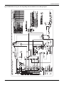
6,1*/(67$*(
7+(50267$7
0LQLPXPZLUHVL]HRI$:*
ZLUHVKRXOGEHXVHGIRUDOOILHOG
LQVWDOOHGYROWZLUH
5
81,7&21752/%2$5'
7(50,1$/675,3
127(+($7$17,&,3$725
6+28/'%(6(7$7
$036)25$//02'(/6
5
*
*
<
<
<<
:
:
&
&
-803(51(('(')25)8//63(('
&2035(662523(5$7,21
92/7
75$16)250(5
352*5$00$%/(
7+(50267$721/<
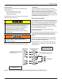
Figure 7: Typical Field Control Wiring Diagram Single Stage Thermostat - Single Stage Gas Heat
10
Unitary Products Group
279550-YIM-A-0207
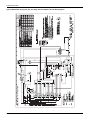
SINGLE STAGE
THERMOSTAT
** = Minimum wire size of 18 AWG
wire should be used for all field
installed 24 volt wire.
R
UNIT CONTROL BOARD
TERMINAL STRIP
**
NOTE: HEAT ANTICIPATOR
SHOULD BE SET AT 0.35
AMPS FOR ALL MODELS.
R
G
G
Y
Y1
JUMPER NEEDED FOR FULL SPEED
COMPRESSOR OPERATION
24 VOLT
TRANSFORMER
Y/Y2
W1
W
W2
C
C
PROGRAMMABLE
THERMOSTAT ONLY
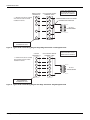
Figure 8: Typical Field Control Wiring Diagram Single Stage Thermostat - Two Stage Gas Heat
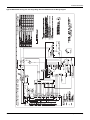
67$*(
7+(50267$7
0LQLPXPZLUHVL]HRI$:*
ZLUHVKRXOGEHXVHGIRUDOOILHOG
LQVWDOOHGYROWZLUH
5
81,7&21752/%2$5'
7(50,1$/675,3
127(+($7$17,&,3$725
6+28/'%(6(7$7
$036)25$//02'(/6
5
*
*
<
<
<
<<
:
:
&
&
92/7
75$16)250(5
352*5$00$%/(
7+(50267$721/<
Figure 9: Typical Field Control Wiring Diagram Two Stage Thermostat - Single Stage Gas Heat
Unitary Products Group
11
279550-YIM-A-0207
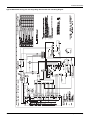
2 STAGE
THERMOSTAT
** = Minimum wire size of 18 AWG
wire should be used for all field
installed 24 volt wire.
UNIT CONTROL BOARD
TERMINAL STRIP
**
R
NOTE: HEAT ANTICIPATOR
SHOULD BE SET AT 0.35
AMPS FOR ALL MODELS.
R
G
G
Y1
Y1
Y2
Y/Y2
W1
W1
W2
W2
C
C
24 VOLT
TRANSFORMER
PROGRAMMABLE
THERMOSTAT ONLY
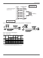
Figure 10: Typical Field Control Wiring Diagram Two Stage Thermostat - Two Stage Gas Heat
Figure 11: Typical Field Power Wiring Diagram
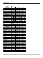
Table 6:
Size
(Tons)
Electrical Data
Volt
RLA LRA
024
(2.0)
036
(3.0)
048
(4.0)
OD Fan
Motors
(each)
Supply
Blower
Motor
MCC
FLA
FLA
Compressors
(each)
MCA1
(Amps)
Max
Fuse2/
Breaker3
Size
(Amps)
208/230-1-60 10.2
52
16
1.4
4.3
18.1
25
208/230-1-60
208/230-3-60
460-3-60
208/230-1-60
208/230-3-60
460-3-60
82
58
29
96
88
41
26
17
7
33
21
10
0.9
0.9
0.5
1.8
1.8
0.9
9.1
9.1
4.6
9.1
9.1
4.6
30.7
23.8
10.7
36.3
26.7
13.0
40
30
15
45
35
15
16.6
11.1
4.5
21.1
13.4
6.4
1. Minimum Circuit Ampacity.
2. Maximum Over Current Protection per standard UL 1995.
3. Fuse or HACR circuit breaker size installed at factory or field installed.
12
Unitary Products Group
279550-YIM-A-0207
DNX024-048 Single Stage Gas Heat
Component
Nominal Tonnage
ARI COOLING PERFORMANCE
Gross Capacity @ ARI A point (Btu)
ARI net capacity (Btu)
EER
SEER
Nominal CFM
System power (KW)
Refrigerant type
Refrigerant charge (lb-oz)
ARI HEATING PERFORMANCE
Heating model
Heat input (K Btu)
Heat output (K Btu)
AFUE %
Steady state efficiency (%)
No. burners
No. stages
Temperature Rise Range (ºF)
Gas Limit Setting (ºF)
Gas piping connection (in.)
DIMENSIONS (inches)
Length
Width
Height
OPERATING WT. (lbs.)
COMPRESSORS
Type
Quantity
CONDENSER COIL DATA
Face area (Sq. Ft.)
Rows
Fins per inch
Tube diameter (in.)
Circuitry Type
EVAPORATOR COIL DATA
Face area (Sq. Ft.)
Rows
Fins per inch
Tube diameter
Circuitry Type
Refrigerant control
CONDENSER FAN DATA
Quantity
Fan diameter (Inch)
Type
Drive type
No. speeds
Number of motors
Motor HP each
RPM
Nominal total CFM
DIRECT DRIVE EVAP FAN DATA
Quantity
Fan Size (Inch)
Type
Motor HP each
RPM
Frame size
FILTERS
Quantity - Size
Unitary Products Group
DNX024
2.0
Models
DNX036
3.0
DNX048
4.0
24.6
24.0
11.5
15.0
800
2.1
R-410A
7-8
38.4
37.0
12.3
16.5
1275
3.0
R-410A
9-12
50.0
48.0
11.2
15.0
1550
4.3
R-410A
9-8
36
45
36
80.0
80
2
1
25-55
140
56
70
56
80.0
80
3
1
30-60
160
65
80
64
80.0
80
3
1
25-55
140
90
108
87
80.0
80
4
1
45-75
160
65
80
64
80.0
80
3
1
25-55
150
1/2
1/2
90
108
87
80.0
80
4
1
35-65
170
1/2
110
135
108
80.0
80
5
1
45-75
160
49 1/8
47 1/4
33 1/2
440
49 1/8
47 1/4
41 1/2
480
49 1/8
47 1/4
41 1/2
500
Scroll 2-spd
1
Scroll 2-spd
1
Scroll 2-spd
1
11.7
2
20
3/8
Interlaced
14.7
2
20
3/8
Interlaced
14.7
2
20
3/8
Interlaced
3.4
2
15
3/8
Interlaced
TXV
4.4
3
16
3/8
Interlaced
TXV
4.4
3
16
3/8
Interlaced
TXV
1
22
Prop
Direct
1
1
1/4
1100
2400
1
22
Prop
Direct
2
1
1/3
900/1100
2400
1
22
Prop
Direct
1
2
1/3
900/1100
3000
1
10 x 8
Centrifugal
1/2
Variable
48
1
11 x 10
Centrifugal
1
Variable
48
1
11 x 10
Centrifugal
1
Variable
48
1 - 20 x 20 x 1
2 - 20 x 12 x 1
2 - 20 x 12 x 1
13
279550-YIM-A-0207
DNX024-048 Two Stage Gas Heat
Component
Nominal Tonnage
ARI COOLING PERFORMANCE
Gross Capacity @ ARI A point (Btu)
ARI net capacity (Btu)
EER
SEER
Nominal CFM
System power (KW)
Refrigerant type
Refrigerant charge (lb-oz)
ARI HEATING PERFORMANCE
Heating model
Heat input (K Btu)
Heat output (K Btu)
AFUE %
Steady state efficiency (%)
No. burners
No. stages
Temperature Rise Range (ºF)
Gas Limit Setting (ºF)
Gas piping connection (in.)
DIMENSIONS (inches)
Length
Width
Height
OPERATING WT. (lbs.)
COMPRESSORS
Type
Quantity
CONDENSER COIL DATA
Face area (Sq. Ft.)
Rows
Fins per inch
Tube diameter (in.)
Circuitry Type
EVAPORATOR COIL DATA
Face area (Sq. Ft.)
Rows
Fins per inch
Tube diameter
Circuitry Type
Refrigerant control
CONDENSER FAN DATA
Quantity
Fan diameter (Inch)
Type
Drive type
No. speeds
Number of motors
Motor HP each
RPM
Nominal total CFM
DIRECT DRIVE EVAP FAN DATA
Quantity
Fan Size (Inch)
Type
Motor HP each
RPM
Frame size
FILTERS
Quantity - Size
14
DNX024
2.0
Models
DNX036
3.0
DNX048
4.0
24.6
24.0
11.5
15.0
800
2.1
R-410A
7-8
38.4
37.0
12.3
16.5
1275
3.0
R-410A
9-12
50.0
48.0
11.2
15.0
1550
4.3
R-410A
9-8
56
70/45.5
56/36.4
80.0
80
3
2
30-60
160
1/2
90
108/70.2
87/56.2
80.0
80
4
2
45-75
175
1/2
90
110
108/70.2 135/87.8
87/56.2 108/70.2
80.0
80.0
80
80
4
5
2
2
35-65
45-75
170
160
1/2
49 1/8
47 1/4
33 1/2
440
49 1/8
47 1/4
41 1/2
480
49 1/8
47 1/4
41 1/2
500
Scroll 2-spd
1
Scroll 2-spd
1
Scroll 2-spd
1
11.7
2
20
3/8
Interlaced
14.7
2
20
3/8
Interlaced
14.7
2
20
3/8
Interlaced
3.4
2
15
3/8
Interlaced
TXV
4.4
3
16
3/8
Interlaced
TXV
4.4
3
16
3/8
Interlaced
TXV
1
22
Prop
Direct
1
1
1/4
1100
2400
1
22
Prop
Direct
2
1
1/3
900/1100
2400
1
22
Prop
Direct
1
2
1/3
900/1100
3000
1
10 x 8
Centrifugal
1/2
Variable
48
1
11 x 10
Centrifugal
1
Variable
48
1
11 x 10
Centrifugal
1
Variable
48
1 - 20 x 20 x 1
2 - 20 x 12 x 1
2 - 20 x 12 x 1
Unitary Products Group
279550-YIM-A-0207
Compressors
The scroll compressor used in this product is specifically
designed to operate with R-410A Refrigerant and cannot be
interchanged.
Scroll compressors require proper rotation to operate
properly. Failure to check and correct rotation may result
in property damage.
Gas Heat
This system uses R-410A Refrigerant which operates at
higher pressures than R-22. No other refrigerant may be
used in this system.
These single or two stage gas-fired heaters have aluminizedsteel tubular heat exchangers with spark to pilot ignition.
Gas Piping
The compressor also uses a polyolester (POE oil), Mobil 3MA
POE. This oil is extremely hydroscopic, meaning it absorbs
water readily. POE oil can absorb 15 times as much water as
other oils designed for HCFC and CFC refrigerants. Take all
necessary precautions to avoid exposure of the oil to the
atmosphere.
Proper sizing of gas piping depends on the cubic feet per hour
of gas flow required, specific gravity of the gas and the length of
run. National Fuel Gas Code Z223.1 or CSA B149.1 should be
followed in all cases unless superseded by local codes or gas
company requirements. Refer to Tables 7 and 8.
The heating value of the gas may differ with locality. The value
should be checked with the local gas utility.
Do not leave the system open to the atmosphere. Unit
damage could occur due to moisture being absorbed by
the POE oil in the system. This type of oil is highly
susceptible to moisture absorption
POE (polyolester) compressor lubricants are known to cause
long term damage to some synthetic roofing materials.
NOTE: There may be a local gas utility requirement specifying
a minimum diameter for gas piping. All units require a
1/2 inch pipe connection at the gas valve.
Gas Connection
The gas supply line can be routed through the hole located on
the left side of the unit. Refer to Figure 3 to locate these access
openings. Typical supply piping arrangements are shown in
Figure 12.
Gas piping requirements:
Exposure, even if immediately cleaned up, may cause
embrittlement (leading to cracking) to occur in one year
or more. When performing any service that may risk
exposure of compressor oil to the roof, take precautions
to protect roofing.
Procedures which risk oil leakage include, but are not limited to,
compressor replacement, repairing refrigerant leaks, replacing
refrigerant components such as filter drier, pressure switch,
metering device or coil.
Units are shipped with compressor mountings which are
factory-adjusted and ready for operation.
1.
A drip leg and a ground joint union must be installed in the
gas piping.
2.
When required by local codes, a manual shut-off valve may
have to be installed outside of the unit.
3.
Use wrought iron or steel pipe for all gas lines. Pipe dope
should be applied sparingly to male threads only.
$8720$7,&*$69$/9(
[81,21
[*$6&2&.
Do not loosen compressor mounting bolts.
Phasing
Three-phase, scroll compressors operate in only one direction.
If the scroll is drawing low amperage, has similar suction and
discharge pressures, or is producing a high noise level, the
scroll is misphased. Change the incoming line connection
phasing to obtain the proper rotation.
137
'5,3/(*
Figure 12: External Supply Connection External Shut-Off
Unitary Products Group
15
279550-YIM-A-0207
Table 7:
Length
In Feet
10
20
30
40
50
60
70
80
90
100
Natural Gas Pipe Sizing Chart1
1/2”
132
92
73
63
56
50
46
43
40
38
Limitations, shown on Page 3. After the gas connections
have been completed, open the main shut-off valve
admitting normal gas pressure to the mains. Check all
joints for leaks with soap solution or other material suitable
for the purpose. NEVER USE A FLAME.
Nominal Inches Iron Pipe Size
3/4”
1”
1-1/4”
278
520
1,050
190
350
730
152
285
590
130
245
500
115
215
440
105
195
400
96
180
370
90
170
350
84
160
320
79
150
305
FIRE OR EXPLOSION HAZARD
Failure to follow the safety warning exactly could result
in serious injury, death or property damage.
Never test for gas leaks with an open flame. use a
commercially available soap solution made specifically
for the detection of leaks to check all connections. A fire
or explosion may result causing property damage,
personal injury or loss of life.
1. Maximum capacity of pipe in cubic feet of gas per hour
(based upon a pressure drop of 0.3 inch water column and
0.6 specific gravity gas).
Table 8:
Length
In Feet
10
20
30
40
50
60
70
80
90
100
Propane (LP) Gas Pipe Sizing Chart1
1/2”
275
189
152
129
114
103
96
89
83
78
Nominal Inches Iron Pipe Size
3/4”
1”
1-1/4”
567
1,071
2,205
393
732
1,496
315
590
1,212
267
504
1,039
237
448
913
217
409
834
196
378
771
185
346
724
173
322
677
162
307
630
6.
The furnace must be isolated from the gas supply piping
system by closing its individual manual shut-off valve
before conducting any pressure testing of the gas supply
piping system at test pressures equal to or less than 1/2
psig (3.48 kPa).
Flue Vent Hood
The flue vent hood with screen is shipped loose. This hood must
be installed to assure proper unit operation. The hood must be
fastened to the outside of the side gas control/electrical
compartment with the screws provided in the bag attached to the
inside of the gas control/electrical compartment, see Figure 13.
1. Maximum capacity of pipe in thousands of BTU per hour
(based upon a pressure drop of 0.5 inch water column).
Flue hood surfaces may be hot.
If flexible stainless steel tubing is allowed by the
authority having jurisdiction, wrought iron or steel pipe
must be installed at the gas valve and extend a
minimum of two (2) inches outside of the unit casing.
Natural gas may contain some propane. Propane being
an excellent solvent, will quickly dissolve white lead or
most standard commercial compounds. Therefore, a
special pipe dope must be applied when wrought iron or
steel pipe is used. Shellac base compounds such as
gaskoloc or stalastic, and compounds such as
rectorseal # 5, Clyde’s or John Crane may be used.
4.
All piping should be cleaned of dirt and scale by
hammering on the outside of the pipe and blowing out the
loose dirt and scale. Before initial start-up, be sure that all
of the gas lines external to the unit have been purged of air.
5.
The gas supply should be a separate line and installed in
accordance with all safety codes as prescribed under
16
9(17287/(76&5((1
)/8(9(17287/(7
$,5+22'
Figure 13: Flue Vent Outlet Air Hood
The flue exhaust hood must be properly installed and
within the recommended clearances. Further communications and action must be given to the home or
building owner(s) to eliminate any unauthorized human
contact around this area during the heating cycle. Flue
hood surface and the immediate area reach high temperatures during the heating cycle.
Unitary Products Group
279550-YIM-A-0207
Table 9:
Natural Gas Application Data-Single Stage
Available On Models
Input
(MBH)1
Output
(MBH)
Gas Rate2
Ft.3/Hr.
Number of
Burners
2 Ton
2 Ton
3,4 Ton
3 Ton
4 Ton
4 Ton
45
70
80
108
108
135
36
56
64
87
87
108
42
65
74
100
100
126
2
3
3
4
4
5
Temp. Rise ºF
At Full Input3
Min.
Max.
25
55
30
60
25
55
45
75
35
65
45
75
1. Heating capacity valid for elevations up to 2000 feet above sea level. For elevations above 2,000 feet, rated capacity should be reduced by
4% for each 1,000 feet above sea level.
2. Based on 1075 BTU/Ft.3.
3. The air flow must be adequate to obtain a temperature rise within the range shown. Continuous return air temperature should not be below 55°F.
Table 10: Natural Gas Application Data-Two Stage
Available On Models
2 Ton
3 Ton
4 Ton
4 Ton
Input
(MBH)1
High Fire/Low Fire
70 / 45.5
108 / 70.2
108 / 70.2
135 / 87.75
Output
(MBH)
High Fire/Low Fire
56 / 36.4
87 / 56.2
87 / 56.2
108 / 70.2
Gas Rate2
Ft.3/Hr.
High Fire/Low Fire
65 / 42
100 / 65
100 / 65
126 / 82
Number of
Burners
3
4
4
5
Temp. Rise ºF
At Full Input3
Min.
Max.
30
60
45
75
35
65
45
75
1. Heating capacity valid for elevations up to 2000 feet above sea level. For elevations above 2,000 feet, rated capacity should be reduced by
4% for each 1,000 feet above sea level.
2. Based on 1075 BTU/Ft.3.
3. The air flow must be adequate to obtain a temperature rise within the range shown. Continuous return air temperature should not be below 55°F.
Table 11: Propane1 (LP) Gas Application Data-Single Stage
Available On Models
Input Capacity
(Mbh)2
Output Capacity
(Mbh)
Gas Rate3
Ft.3/Hr.
Number of Burners
2 Ton
2 Ton
3,4 Ton
3 Ton
4 Ton
4 Ton
45
70
80
108
108
135
36
56
64
87
87
108
18
28
32
43
43
54
2
3
3
4
4
5
Temp. Rise ºF
At Full Input4
Min.
Max.
25
55
30
60
25
55
45
75
35
65
45
75
1. Propane applications are accomplished by field installation of a Propane Conversion Accessory, Model 1NP0807 for 2 Ton unit with 33-1/2”
tall cabinet and Model 1NP0808 for 3 and 4 Ton units with 41-1/2” tall cabinets.
2. Heating capacity valid for elevations up to 2,000 feet above sea level. For elevations above 2,000 feet, rated capacity should be reduced
by 4% for each 1,000 feet above sea level.
3. Based on 2500 BTU/Ft.3.
4. The air flow must be adequate to obtain a temperature rise within the range shown. Continuous return air temperature should not be below 55°F.
Table 12: Propane1 (LP) Gas Application Data-Two Stage
Available On Models
2 Ton
3 Ton
4 Ton
4 Ton
Input Capacity
(Mbh)2
High Fire/Low Fire
70 / 45.5
108 / 70.2
108 / 70.2
135 / 87.75
Output Capacity
(Mbh)
High Fire/Low Fire
56 / 36.4
87 / 56.2
87 / 56.2
108 / 70.2
Gas Rate3
Ft.3/Hr.
High Fire/Low Fire
28 / 18.2
43 / 27.95
43 / 27.95
54 / 35.1
Number of Burners
3
4
4
5
Temp. Rise ºF
At Full Input4
Min.
Max.
30
60
45
75
35
65
45
75
1. Propane applications are accomplished by field installation of a Propane Conversion Accessory, Model 1NP0809 for 2 Ton unit with 33-1/2”
tall cabinet and Model 1NP0810 for 3 and 4 Ton units with 41-1/2” tall cabinets.
2. Heating capacity valid for elevations up to 2,000 feet above sea level. For elevations above 2,000 feet, rated capacity should be reduced
by 4% for each 1,000 feet above sea level.
3. Based on 2500 BTU/Ft.3.
4. The air flow must be adequate to obtain a temperature rise within the range shown. Continuous return air temperature should not be below 55°F.
Unitary Products Group
17
279550-YIM-A-0207
Airflow Performance
Table 13: Side Duct Application
Size
(Tons)
Mode
Low
Cool
High
N036
024
(2.0)
N056
Heat
D056
Low
Cool
High
N065
036
(3.0)
N090
Heat
D090
Low
048
(4.0)
Cool
High
18
Thermostat
Input
Speed
Tap
CFM
Y1
Y1
Y1
Y1
Y1+Y2
Y1+Y2
Y1+Y2
Y1+Y2
W1
W1
W1
W1
W1
W1
W1
W1
W1
W1
W1
W1
W1+W2
W1+W2
W1+W2
W1+W2
Y1
Y1
Y1
Y1
Y1+Y2
Y1+Y2
Y1+Y2
Y1+Y2
W1
W1
W1
W1
W1
W1
W1
W1
W1
W1
W1
W1
W1+W2
W1+W2
W1+W2
W1+W2
Y1
Y1
Y1
Y1
Y1+Y2
Y1+Y2
Y1+Y2
Y1+Y2
COOL-A
COOL-B
COOL-C
COOL-D
COOL-A
COOL-B
COOL-C
COOL-D
HEAT-A
HEAT-B
HEAT-C
HEAT-D
HEAT-A
HEAT-B
HEAT-C
HEAT-D
HEAT-A
HEAT-B
HEAT-C
HEAT-D
HEAT-A
HEAT-B
HEAT-C
HEAT-D
COOL-A
COOL-B
COOL-C
COOL-D
COOL-A
COOL-B
COOL-C
COOL-D
HEAT-A
HEAT-B
HEAT-C
HEAT-D
HEAT-A
HEAT-B
HEAT-C
HEAT-D
HEAT-A
HEAT-B
HEAT-C
HEAT-D
HEAT-A
HEAT-B
HEAT-C
HEAT-D
COOL-A
COOL-B
COOL-C
COOL-D
COOL-A
COOL-B
COOL-C
COOL-D
600
450
530
680
800
600
700
900
670
730
790
850
940
975
1000
1050
670
690
710
750
940
970
1000
1050
900
760
830
970
1250
1050
1150
1350
1200
1300
1400
1500
1150
1225
1275
1350
740
785
825
870
1150
1220
1280
1350
1030
930
1070
1130
1550
1400
1600
1700
External Static Pressure (Inch Water Gauge)
0.2
0.3
0.4
0.5
0.6
0.7
0.8
0.9
1.0
Watts Watts Watts Watts Watts Watts Watts Watts Watts
100
122
145
169
194
221
249
279
310
65
81
100
122
147
176
208
243
281
81
100
121
145
170
197
226
258
291
127
151
176
202
228
256
284
313
342
177
204
232
261
290
320
350
382
414
100
122
145
169
194
221
249
279
310
134
159
184
211
238
265
293
323
352
229
258
288
319
351
385
420
457
494
123
147
172
197
224
251
146
172
198
225
252
280
173
199
227
255
284
314
202
230
259
289
319
351
253
281
312
344
378
274
303
334
368
403
290
319
351
385
422
324
353
386
422
461
123
147
172
197
224
130
155
180
206
233
138
163
189
215
242
155
181
207
235
262
253
281
312
344
378
271
300
331
364
400
290
319
351
385
422
324
353
386
422
461
198
233
272
313
358
406
458
512
569
166
190
222
262
310
366
431
503
584
180
210
245
286
332
384
441
503
571
221
260
302
344
388
434
481
530
579
361
408
454
501
548
594
640
687
733
253
296
340
384
428
472
516
561
605
302
348
394
439
484
528
571
615
657
429
475
522
570
620
671
723
777
831
330
377
423
469
515
560
394
440
487
535
583
631
467
511
558
607
659
713
550
590
635
686
743
804
302
348
394
439
484
528
345
392
439
485
531
577
377
424
471
518
565
612
429
475
522
570
620
671
163
185
216
255
304
362
170
196
230
270
317
372
178
208
243
284
330
382
189
223
260
301
347
396
302
348
394
439
484
528
342
389
436
482
528
573
380
427
474
521
568
616
429
475
522
570
620
671
237
280
323
367
411
455
499
543
588
192
237
282
326
369
413
455
497
539
257
300
343
386
430
475
520
565
611
289
332
375
419
463
509
555
602
649
586
640
696
752
810
869
929
991
1053
466
513
561
611
663
715
770
826
882
630
687
745
804
864
926
988
1052 1116
723
787
851
916
982
1049 1116 1185
-
Unitary Products Group
279550-YIM-A-0207
Table 13: Side Duct Application (Continued)
Size
(Tons)
Mode
Thermostat
Input
Speed
Tap
CFM
W1
W1
W1
W1
W1
W1
W1
W1
W1
W1
W1
W1
W1+W2
W1+W2
W1+W2
W1+W2
W1
W1
W1
W1
W1
W1
W1
W1
W1+W2
W1+W2
W1+W2
W1+W2
HEAT-A
HEAT-B
HEAT-C
HEAT-D
HEAT-A
HEAT-B
HEAT-C
HEAT-D
HEAT-A
HEAT-B
HEAT-C
HEAT-D
HEAT-A
HEAT-B
HEAT-C
HEAT-D
HEAT-A
HEAT-B
HEAT-C
HEAT-D
HEAT-A
HEAT-B
HEAT-C
HEAT-D
HEAT-A
HEAT-B
HEAT-C
HEAT-D
1200
1300
1400
1500
1325
1400
1500
1600
870
920
985
1050
1330
1400
1500
1600
1450
1500
1600
1700
940
970
1050
1100
1450
1500
1600
1700
Thermostat
Input
Speed
Tap
CFM
Y1
Y1
Y1
Y1
Y1+Y2
Y1+Y2
Y1+Y2
Y1+Y2
W1
W1
W1
W1
W1
W1
W1
W1
W1
W1
W1
W1
W1+W2
W1+W2
W1+W2
W1+W2
COOL-A
COOL-B
COOL-C
COOL-D
COOL-A
COOL-B
COOL-C
COOL-D
HEAT-A
HEAT-B
HEAT-C
HEAT-D
HEAT-A
HEAT-B
HEAT-C
HEAT-D
HEAT-A
HEAT-B
HEAT-C
HEAT-D
HEAT-A
HEAT-B
HEAT-C
HEAT-D
600
450
530
680
800
600
700
900
670
730
790
850
940
975
1000
1050
670
690
710
750
940
970
1000
1050
N065
N090
D090
048
(4.0)
Heat
N110
D110
External Static Pressure (Inch Water Gauge)
0.2
0.3
0.4
0.5
0.6
0.7
0.8
0.9
1.0
Watts Watts Watts Watts Watts Watts Watts Watts Watts
330
373
416
461
507
554
394
439
484
531
579
629
466
513
561
611
663
715
544
596
648
702
758
815
412
456
503
550
599
649
466
513
561
611
663
715
544
596
648
702
758
815
630
687
745
804
864
926
168
215
261
306
350
393
188
233
278
322
366
409
216
260
303
347
391
434
247
290
333
376
420
464
415
460
506
554
603
653
466
513
561
611
663
715
544
596
648
702
758
815
630
687
745
804
864
926
504
553
604
656
544
596
648
702
630
687
745
804
723
787
851
916
196
241
285
329
209
253
297
341
247
290
333
376
273
315
358
402
504
553
604
656
544
596
648
702
630
687
745
804
723
787
851
916
-
Table 14: Bottom Duct Application
Size
(Tons)
Mode
Low
Cool
High
N036
024
(2.0)
N056
Heat
D056
Unitary Products Group
External Static Pressure (Inch Water Gauge)
0.2
0.3
0.4
0.5
0.6
0.7
0.8
0.9
1.0
Watts Watts Watts Watts Watts Watts Watts Watts Watts
100
122
145
169
194
221
249
279
310
65
81
100
122
147
176
208
243
281
81
100
121
145
170
197
226
258
291
127
151
176
202
228
256
284
313
342
177
204
232
261
290
320
350
382
414
100
122
145
169
194
221
249
279
310
134
159
184
211
238
265
293
323
352
229
258
288
319
351
385
420
457
494
123
147
172
197
224
251
146
172
198
225
252
280
173
199
227
255
284
314
202
230
259
289
319
351
253
281
312
344
378
274
303
334
368
403
290
319
351
385
422
324
353
386
422
461
123
147
172
197
224
130
155
180
206
233
138
163
189
215
242
155
181
207
235
262
253
281
312
344
378
271
300
331
364
400
290
319
351
385
422
324
353
386
422
461
-
19
279550-YIM-A-0207
Table 14: Bottom Duct Application (Continued)
Size
(Tons)
Mode
Low
Cool
High
N065
036
(3.0)
N090
Heat
D090
Low
Cool
High
N065
N090
048
(4.0)
D090
Heat
N110
D110
20
Thermostat
Input
Speed
Tap
CFM
Y1
Y1
Y1
Y1
Y1+Y2
Y1+Y2
Y1+Y2
Y1+Y2
W1
W1
W1
W1
W1
W1
W1
W1
W1
W1
W1
W1
W1+W2
W1+W2
W1+W2
W1+W2
Y1
Y1
Y1
Y1
Y1+Y2
Y1+Y2
Y1+Y2
Y1+Y2
W1
W1
W1
W1
W1
W1
W1
W1
W1
W1
W1
W1
W1+W2
W1+W2
W1+W2
W1+W2
W1
W1
W1
W1
W1
W1
W1
W1
W1+W2
W1+W2
W1+W2
W1+W2
COOL-A
COOL-B
COOL-C
COOL-D
COOL-A
COOL-B
COOL-C
COOL-D
HEAT-A
HEAT-B
HEAT-C
HEAT-D
HEAT-A
HEAT-B
HEAT-C
HEAT-D
HEAT-A
HEAT-B
HEAT-C
HEAT-D
HEAT-A
HEAT-B
HEAT-C
HEAT-D
COOL-A
COOL-B
COOL-C
COOL-D
COOL-A
COOL-B
COOL-C
COOL-D
HEAT-A
HEAT-B
HEAT-C
HEAT-D
HEAT-A
HEAT-B
HEAT-C
HEAT-D
HEAT-A
HEAT-B
HEAT-C
HEAT-D
HEAT-A
HEAT-B
HEAT-C
HEAT-D
HEAT-A
HEAT-B
HEAT-C
HEAT-D
HEAT-A
HEAT-B
HEAT-C
HEAT-D
HEAT-A
HEAT-B
HEAT-C
HEAT-D
900
760
830
970
1250
1050
1150
1350
1200
1300
1400
1500
1150
1225
1275
1350
740
785
825
870
1150
1220
1280
1350
1030
930
1070
1130
1550
1400
1600
1700
1200
1300
1400
1500
1325
1400
1500
1600
870
920
985
1050
1330
1400
1500
1600
1450
1500
1600
1700
940
970
1050
1100
1450
1500
1600
1700
External Static Pressure (Inch Water Gauge)
0.2
0.3
0.4
0.5
0.6
0.7
0.8
0.9
1.0
Watts Watts Watts Watts Watts Watts Watts Watts Watts
198
233
272
313
358
406
458
512
569
166
190
222
262
310
366
431
503
584
180
210
245
286
332
384
441
503
571
221
260
302
344
388
434
481
530
579
361
408
454
501
548
594
640
687
733
253
296
340
384
428
472
516
561
605
302
348
394
439
484
528
571
615
657
429
475
522
570
620
671
723
777
831
330
377
423
469
515
560
394
440
487
535
583
631
467
511
558
607
659
713
550
590
635
686
743
804
302
348
394
439
484
528
345
392
439
485
531
577
377
424
471
518
565
612
429
475
522
570
620
671
163
185
216
255
304
362
170
196
230
270
317
372
178
208
243
284
330
382
189
223
260
301
347
396
302
348
394
439
484
528
342
389
436
482
528
573
380
427
474
521
568
616
429
475
522
570
620
671
237
280
323
367
411
455
499
543
588
192
237
282
326
369
413
455
497
539
257
300
343
386
430
475
520
565
611
289
332
375
419
463
509
555
602
649
586
640
696
752
810
869
929
991
1053
466
513
561
611
663
715
770
826
882
630
687
745
804
864
926
988
1052 1116
723
787
851
916
982
1049 1116 1185
330
373
416
461
507
554
394
439
484
531
579
629
466
513
561
611
663
715
544
596
648
702
758
815
412
456
503
550
599
649
466
513
561
611
663
715
544
596
648
702
758
815
630
687
745
804
864
926
168
215
261
306
350
393
188
233
278
322
366
409
216
260
303
347
391
434
247
290
333
376
420
464
415
460
506
554
603
653
466
513
561
611
663
715
544
596
648
702
758
815
630
687
745
804
864
926
504
553
604
656
544
596
648
702
630
687
745
804
723
787
851
916
196
241
285
329
209
253
297
341
247
290
333
376
273
315
358
402
504
553
604
656
544
596
648
702
630
687
745
804
723
787
851
916
-
Unitary Products Group
279550-YIM-A-0207
Table 15: Additional Static Resistance
Size
(Tons)
024
(2.0)
036
(3.0)
048
(4.0)
CFM
Wet Indoor Coil
Economizer1
Filter/Frame Kit
Electric Heat
500
0.01
0.00
0.01
-
600
0.01
0.00
0.02
-
700
0.01
0.00
0.04
-
800
0.02
0.01
0.06
-
900
0.03
0.01
0.08
-
1000
0.04
0.01
0.10
-
1100
0.05
0.01
0.13
-
1200
0.06
0.02
0.16
-
700
0.01
0.00
0.04
-
800
0.02
0.01
0.06
-
900
0.03
0.01
0.08
-
1000
0.04
0.01
0.10
-
1100
0.05
0.01
0.13
-
1200
0.06
0.02
0.16
-
1300
0.07
0.03
0.17
-
1400
0.08
0.04
0.18
-
1100
0.02
0.02
0.04
-
1200
0.03
0.02
0.04
-
1300
0.04
0.02
0.05
-
1400
0.05
0.03
0.05
-
1500
0.06
0.04
0.06
-
1600
0.07
0.04
0.07
-
1700
0.07
0.04
0.08
-
1800
0.08
0.04
0.09
-
1900
0.09
0.05
0.10
-
2000
0.09
0.05
0.11
-
1. The pressure drop through the economizer is greater for 100% outdoor air than for 100% return air. If the resistance
of the return air duct is less than 0.25 IWG, the unit will deliver less CFM during full economizer operation.
To Set Cooling CFM for DNX Units:
Table 16: Indoor Blower Specifications
Size
(Tons)
024
(2.0)
036
(3.0)
048
(4.0)
HP
RPM
Motor
Eff.
1/2
Variable
0.8
1.0
48
1
Variable
0.8
1.0
48
1
Variable
0.8
1.0
48
SF
Frame
Refer to Airflow Performance Tables 13 and 14 for the possible
cooling speed CFM selections.
Set “COOL” and “ADJ” Jumpers on the CFM selection board as
indicated in Tables 13, 14 and Figure 14.
NOTE: CFM indicator light flashes once for every 100 CFM
(i.e. 12 flashes = 1200 CFM).
Blower Speed Selection
The variable speed blowers are designed to deliver constant
CFM regardless of the external static pressure (ESP) in the
ductwork. Therefore, if too many supply registers are closed, a
filter becomes clogged, or there is a restriction in the ductwork,
the motor will automatically operate at a higher speed to
compensate for the higher ESP. This may result in a higher
operating sound level.
These units have variable speed motors that automatically
adjust to provide constant CFM from 0.2" to 0.6" w.c. static
pressure. From 0.6" to 1.0" static pressure, CFM is reduced by
2% per 0.1" increase in static. Operation on duct systems with
greater than 1.0" w.c. external static pressure is not
recommended.
Unitary Products Group
Do not change the "ADJ" tab position on the CFM
selection board as this will change your cooling CFM
previously selected.
To Set Delay Profile:
Every unit has multiple cooling “blower off delay” profiles to
optimize system performance and efficiency. Refer to Table 17
for the regional climate in your area. Place the “DELAY” jumper
tap on the CFM selection board on the appropriate pin setting.
Factory Set Gas Heat CFM:
The blower speed required for gas heat is different than for
cooling. The heating CFM is factory set, but is adjustable.
21
279550-YIM-A-0207
The “Heat” Jumper on the CFM selection board should be
set to “A”.
Fan Only CFM:
When the connection is made from “R” to “G”, the fan only
mode is activated. In this mode, the blower will deliver 75% of
the cooling system CFM. This connection is factory set from the
manufacturer, but can be field adjusted.
:
:
5
<<
to close. When the low pressure switch closes, the control
begins Pre-purge period. If the call for heat is lost, the control
de-energizes the inducer without post-purge and returns to
standby.
If the low pressure switch does not close within 10 seconds of
inducer energizing, the control board flashes “2” on the LED. If
the pressure switch does not close within 5 minutes of inducer
energizing, the control shuts off the inducer for 30 seconds,
then energizes the inducer for another 5 minute try to close the
pressure switch. This cycle continues indefinitely until either the
pressure switch is proved closed, or the call for heat ends.
Pre-purge
The control board monitors the low pressure switch and
ensures it remains closed during pre-purge. If the pressure
switch opens, the control goes back to pressure switch proving
mode. The control waits for a 15 second pre-purge period, then
begins the ignition trial
<
Ignition Trial Period
The control board energizes the pilot gas valve and spark
outputs for an 85 second Ignition trial. The control de-energizes
the spark when flame is sensed and enters a flame stabilization
period.
Figure 14: Control Board Speed Tap Location
Table 17: Delay Profile
Delay Tap
Regional Climate Type
Jumper at “A”
Standard Setting
Jumper at “B”
Humid Climate
Jumper at “C”
Dry Climate
Jumper at “D”
Temperate Climate
Operation
The unit is controlled by a conventional heating/cooling thermostat
common to this class of equipment.
If flame is not established within the ignition trial period, the
control de-energizes the spark and gas valve and begins an
inter-purge period before attempting another ignition trial.
If the call for heat is lost during an ignition trial period, the
control immediately de-energizes spark and gas. The control
runs the inducer motor through a post purge period before deenergizing.
If the pressure switch is lost during an ignition trial period, the
control immediately de-energizes spark and gas. The control
begins pressure switch proving before an inter-purge and reignition attempt.
Pilot Flame Stabilization Period
Heating Sequence Of Operation
Heat
The control board begins a call for heat when W1 is energized
(connected to R). The control ignores W2 until pilot ignition has
been established.
The control checks to see if the pressure switch is open. If the
pressure switch is closed, the control board flashes “3” on the
LED and waits indefinitely for it to open. When the pressure
switch is sensed as open, the control begins pressure switch
proving period. If the call for heat is lost, the control goes back
to Standby.
Pressure Switch Proving
The control board energizes the induced draft motor (High
speed for 2 stage model) and waits for the low pressure switch
22
The control board de-energizes the spark output, and waits for
a 2 second flame stabilization period before energizing the
main gas valve.
If flame is lost during the flame stabilization period, the control
board counts it as a flame loss and retries ignition or locks out
flashing a “5” on the LED.
Heat Blower On Delay
The control board waits for 30 seconds and then energizes the
indoor blower heat speed. Blower on delay time begins at the
start of flame proving period in the trial for ignition.
If the thermostat demand for heat is removed, the control deenergizes the gas valve, energizes the blower on heat speed
and initiates a post-purge and heat blower off delay.
Unitary Products Group
279550-YIM-A-0207
Main Burner Operation
Heat Blower Off Delay
High Heat Warm-up
The control board de-energizes the indoor blower motor after a
delay time as selected by movable shunt (60, 90, 120 or 180
seconds). Blower timing begins when the thermostat is satisfied
or heat cycle was interrupted. The control returns to standby
when the blower off delay is complete.
Two stage models run high heat for the first 60 seconds
following Pilot Flame Stabilization period regardless of W2
demand. If W2 is not energized at the end of this 60 second
period the control de energizes the high gas output and steps
the inducer to low speed. If W2 is energized the control remains
on high heat.
If the thermostat call for heat returns before the blower off delay
is complete, the control begins an ignition sequence with prepurge while the blower off delay continues.
There is no high heat warm-up on single stage models.
Lockout
Low Heat
The control board keeps the pilot gas valve, main gas valve and
induced draft motor energized while continuously monitoring
the call for heat, low pressure switch, and flame status.
If the call for heat (W1) is lost, the control de-energizes the gas
valve and begins post purge.
If low pressure switch opens, the control de-energizes the gas
valve and begins pressure switch proving mode.
If flame is lost, the control de-energizes the gas valve within 2.0
second and counts the flame loss. If flame has been lost more
than 16 times within the same call for heat, the control board
locks out flashing “5” on the LED. If flame has been lost less
than 16 times, the control attempts re-ignition after a 300
second inter-purge period.
High Heat
If the W2 terminal was energized more than 1 second before
W1 at the start of the call for heat, and remains continuously
energized through the call for heat, the control considers it to be
connected to a single stage thermostat and implements a 10
minute Auto staging feature. The 2nd stage thermostat call is
ignored until 10 minutes into steady heat (9 minutes after high
heat warm-up ended).
The control recognizes a call for 2nd stage heat when W2 is
energized (connected to “R”). The control energizes the high
gas output and induced draft motor on high speed.
While in lockout, the control board keeps the pilot gas valve,
main gas valve and induced draft motor de-energized.
Lockouts due to failed ignition or flame losses may be reset by
removing the call for heat (W1) for more than 1 second, but less
than 20 seconds, or by removing power from the control for
over 0.25 seconds. The control will automatically reset lockout
after 60 minutes.
Lockouts due to detected internal control faults will reset after
60 minutes or power interruption.
High Temperature Limit Switch
Any time the high temperature limit switch is open the control
board will run the indoor blower motor on heat speed, the
inducer (on high speed for 2 stage models), de-energize the
gas valve, and flash “6” on the LED. When the high temperature
switch closes, the control will restart the ignition sequence
beginning with pre-purge.
Rollout Switch
If the rollout switch opens for more than 0.25 seconds, the
control board will run the inducer (on high speed for 2 stage
models) for a post-purge period, immediately de-energize the
gas valve, and flash “7” on the LED. The blower output will be
energized during an open rollout condition.
If the rollout switch closes, the control shall remain locked out
until power removed or “W” is removed.
If the call for 2nd stage heat goes away and the 1st stage call
remains, the control de energizes the high gas valve, drops
inducer speed to low, and returns to low heat operation.
Rollout switch lockout shall not reset automatically.
Response to loss of W1, low pressure switch, and flame are
identical to low heat operation.
Power interruptions of any duration shall not cause lockout or
any operation requiring manual intervention.
Post Purge
Flame present with Gas off
The control board runs the induced draft motor for a 30 second
post-purge period, and then de-energizes the inducer. If a call
for heat occurs during post-purge, the control finishes the postpurge, drops inducer out to re-prove open pressure switch
before continuing with the heat cycle.
If flame is sensed for longer than 4.0 seconds during a period
when the gas valve should be closed, the control will enter
lockout flashing “8” on the LED. The control will turn on the
inducer blower while the flame is present.
Unitary Products Group
Power Interruptions
23
279550-YIM-A-0207
Welded Gas Valve Relay Response.
Table 18: Ignition Control Board FLASH CODES
If either or both Pilot and Main Gas valve outputs are sensed to
be off for more than 1 seconds when commanded to be on the
control board shuts off all outputs and enters a hard lockout
If the Pilot valve or Main valve output is sensed to be energized
for more than 1 second when commanded to be off, the control
de-energizes the induced draft motor (if flame is not present) to
attempt to open the pressure switch to de-energize the gas
valve. If the pilot or main gas valve is still sensed as energized
after the inducer has been off for 5 seconds, the control reenergizes the inducer to attempt to vent the unburned gas. In
either case, the control enters a hard lockout. If the pilot or main
valve becomes Un-Welded the inducer will de-energize, but the
control will remain in a hard lockout.
During a hard lockout, the control board LED will remain off and
the control will not respond to any thermostat demands.
The only way to recover from a hard lockout is to remove and
then reapply 24VAC power to the control board.
Safety Controls
The control circuit includes the following safety controls:
1. Limit Switch (LS) - This control is located inside the heat
exchanger compartment and is set to open at the
temperature indicated in the Temperature Controls Table
of the unit wiring diagram. It resets automatically. The limit
switch operates when a high temperature condition caused
by inadequate supply air flow occurs, thus shutting down
the ignition control and closing the main gas valve and
energizing the blower.
2.
Pressure Switch (PS) - If the draft motor should fail, the
pressure switch prevents the ignition controls and gas
valves from being energized.
3.
Flame Sensor - The flame sensor and controls are located
per Proper Flame Adjustment Figure 19. If an ignition
control fails to detect a signal from the flame sensor
indicating the pilot flame is properly ignited, then the main
gas valve will not open.
4.
Rollout Switch (RS) - This switch is located in the burner
vestibule. In the event of a sustained main burner flame
rollout, it shuts off the ignition control and closes the main
gas valve.
Flash Code
On Steady
Heart Beat
1 Flash
2 Flashes
3 Flashes
4 Flashes
5 Flashes
6 Flashes
7 Flashes
8 Flashes
Description
Control Failure - Replace Control
Normal Operation
Not Applicable
Pressure / Centrifugal Switch Open with Inducer On
Pressure / Centrifugal Switch Closed with Inducer Off
Not Applicable
Lock Out From Too Many Flame Losses
High Temperature Switch Open (Primary or Aux.)
Rollout Switch Open
Flame Present With Gas OFF
Cooling Sequence Of Operations
When the thermostat calls for first-stage cooling, the thermostat
terminals G and Y1 energize, signaling the compressor, indoor
blower and outdoor fan to operate. The indoor blower will operate
according to the fan delay profile selected using Table 17.
When the thermostat calls for second-stage cooling the
thermostat terminal Y2 energizes, signaling the compressor
bypass ports to close and the indoor blower to increase speed.
If the outdoor fan motor has an ECM controller, Y2 will also
signal the motor to increase speed.
When the thermostat is satisfied, terminals G, Y1 and Y2 are
de-energized, thus stopping operation of the compressor and
outdoor fan. The indoor blower will remain on according to the
fan delay profile selected using Table 17.
Safety Controls
The control circuit includes the following safety controls:
1.
High Pressure Switch (HP)- This switch protects against
excessive discharge pressures due to a blocked
condenser coil or a condenser motor failure (opens at 625
± 25 psig and resets at 500 ± 25 psig).
2.
Low Pressure Switch (LP)- This switch protects against
loss of refrigerant charge (opens at 7 ± 3 psig and resets at
22 ± 5 psig).
The above pressure switches are specifically designed to
operate with R-410A systems. R-22 pressure switches must not
be used as replacements for the R-410A pressure switches.
NOTE: The manual reset Rollout Switch (RS) must be reset
before allowing furnace operation.
5.
24
Auxiliary Limit Switch (ALS) - This control is located
inside the heat exchanger compartment and is set to open
at 160°F. It is a manual reset switch. If ALS trips, then the
primary limit (LS) has not functioned correctly. Replace the
primary limit LS.
The ability to properly perform maintenance on this
equipment requires certain expertise, mechanical
skills, tools and equipment. If you do not possess
these, do not attempt to perform any maintenance
other than those procedures recommended in this
Installation Manual. Failure to heed this warning could
result in serious injury and possible damage to this
equipment.
Unitary Products Group
279550-YIM-A-0207
Circulating Fan
To Turn Off Gas To Unit
When the thermostat calls for FAN, the thermostat terminal G is
energized signaling the circulating fan to run at the heat speed
2 seconds after the G terminal is energized.
1.
Set the thermostat to the OFF position.
2.
Turn off all electric power to the appliance if service is to be
performed.
If a call for HEAT occurs, the circulating fan continues to run at
the heat speed.
3.
Remove the control access panel.
4.
Turn the gas valve switch to the OFF position. DO NOT
FORCE.
5.
Replace the control access panel.
If a call for COOL occurs, the circulating fan switches to cool
speed according to the fan delay profile selected in Table 17.
When the thermostat ends the call for FAN, the thermostat
terminal G is de-energized, de-energizing the circulating fan.
Start-Up
Post Start Check List
After the entire control circuit has been energized and the
heating section is operating, make the following checks:
1.
Check for gas leaks in the unit piping as well as the supply
piping.
2.
Check for correct manifold gas pressures. See Checking
Gas Input.
3.
Check the supply gas pressure. It must be within the limits
shown on rating nameplate. Supply pressure should be
checked with all gas appliances in the building at full fire. At
no time should the standby gas line pressure exceed 13.5",
nor the operating pressure drop below 4.5" for natural gas
units. If gas pressure is outside these limits, contact the
local gas utility for corrective action.
Prestart Check List
Complete the following checks before starting the unit.
1.
2.
Check the type of gas being supplied. Be sure that it is the
same as listed on the unit nameplate.
Make sure that the vent outlet air hood has been properly
installed.
Operating Instructions
1.
STOP! Read the information on the unit safety label.
2.
Set the thermostat to the OFF position.
Manifold Gas Pressure Adjustment
3.
Turn off all electrical power to the unit.
4.
DO NOT try to light the burners by hand. This appliance is
equipped with an ignition device which automatically lights
the burners.
Small adjustments to the gas flow may be made by turning the
pressure regulator adjusting screw on the automatic gas valve.
Refer to Figures 15 and 16.
5.
Remove the access panel.
6.
Turn the gas valve switch to the OFF position.
7.
Wait five (5) minutes to clear out any gas. If you then smell
gas, STOP! Follow B in the information on the unit safety
label. If you don't smell gas, go to the next step.
8.
Turn the gas valve switch to the ON position.
9.
Replace the control access panel.
10. Turn on all electric power to the unit.
11. Set the thermostat to the desired setting.
12. If the unit will not operate, follow the instructions To Turn
Off Gas To Appliance and call your service technician or
gas supplier.
Unitary Products Group
Manual
Gas Switch
Pilot
Adjustment
(Remove Cap)
Manifold
Pressure
Adjustment
(Remove Cap)
Pilot Gas
Connection
Electrical
Connection
½ NPT
(Outlet)
Manifold
Pressure Tap
Figure 15: Single Stage Gas Valve Front
25
279550-YIM-A-0207
Manual
Gas
Switch
Hi Fire
(2nd Stage)
Manifold Pressure
Low Fire
(1st Stage)
Manifold Pressure
Adjustment
Electrical
Connection
Manifold
Pressure
Tap
Pilot
Adjustment
(Remove Cap)
Pilot
Gas
Connect
Figure 16: Two Stage Gas Valve Front
3.
To increase the gas pressure, turn the adjusting screw
clockwise.
NOTE: The correct manifold pressure for natural gas furnaces
is 3.5 IWG high heat and 1.5 IWG low heat. The correct
manifold pressure for propane (LP) is 10.0 IWG high
heat and 4.5 IWG low heat.
Burner Instructions
To check or change the burners, CLOSE THE MAIN MANUAL
SHUT-OFF VALVE AND SHUT OFF ALL POWER TO THE
UNIT.
1. Remove the two (2) #8 screws holding each burner in place.
2.
Remove the burner assembly from the manifold assembly
by moving the burner assembly forward, turn at an angle
and pull back.
3.
Burners are now accessible for service.
½ NPT
(Outlet)
Pilot Instruction
To adjust the pilot flame:
3 8" min.
½ NPT
(Inlet)
Line
Pressure
Tap
Figure 17: Single Stage Gas Valve Rear
Spark Ignitor
Pilot
Flame Sensor
Figure 19: Proper Flame Adjustment
½ NPT
1.
Remove the pilot adjustment cover screw.
2.
Adjust the pilot adjustment screw to achieve the proper
pilot flame.
3.
The pilot flame should envelope 3/8” of the end of the flame
sensor and not contain any yellow color, see Figure 19.
4.
Replace the pilot adjustment cover screw after the pilot
flame is set.
(Inlet)
Line Pressure
Tap
Figure 18: Two Stage Gas Valve Rear
Adjust as follows:
1. Remove the cap from the valve body. See Figures 15 and
16 for location.
2.
26
To decrease the gas pressure, turn the adjusting screw
counterclockwise.
To check, adjust or remove the pilot assembly, CLOSE THE
MAIN MANUAL SHUT-OFF VALVE AND SHUT OFF ALL
POWER TO THE UNIT.
1.
Disconnect the wiring from the control board to the pilot
assembly.
2.
Remove the two (2) #8 screws holding the pilot assembly
in place.
3.
Remove the pilot assembly.
Unitary Products Group
279550-YIM-A-0207
Adjustment of Temperature Rise
After about 20 minutes of high heat operation, determine the
furnace temperature rise. Take readings of both the return air
and the heated air in the ducts about six feet from the furnace
where they will not be affected by radiant heat.
The temperature rise (or temperature difference between the
return air and the heated air from the furnace) must lie within
the range shown on the rating plate and the data in Tables 9
and 11.
After the temperature rise has been determined, the CFM can
be calculated as follows:
'HJUHHV)7HPS5LVH
%78+2XWSXW
[&)0
25
&)0
%78+2XWSXW
['HJUHHV)7HPS5LVH
Direct Drive Blower
All units have direct drive, constant CFM blower motors.
Checking Gas Heat Input
Natural Gas
1.
Turn off all other gas appliances connected to the gas meter.
2.
With the furnace turned on, measure the time needed for
one revolution of the hand on the smallest dial on the
meter. A typical gas meter usually has a 1/2 or a 1 cubic
foot test dial.
3.
Using the number of seconds for each revolution and the
size of the test dial increment, find the cubic feet of gas
consumed per hour from Table 19.
If the actual input is not within 5% of the furnace rating with
allowance being made for the permissible range of the regulator
setting, replace the orifice spuds with spuds of the proper size.
Unitary Products Group
NOTE: To find the BTU input, multiply the number of cubic feet
of gas consumed per hour by the BTU content of the gas
in your particular locality. (Contact your gas company for
this information since it varies widely from city to city.)
Table 19: Gas Rate Cubic Feet Per Hour1
Seconds for
One Rev.
10
12
14
16
18
20
22
24
26
28
30
32
34
36
38
40
42
44
46
48
50
52
54
56
58
60
Size of Test Dial
1/2 cu. ft.
1 cu. ft.
180
360
150
300
129
257
113
225
100
200
90
180
82
164
75
150
69
138
64
129
60
120
56
113
53
106
50
100
47
95
45
90
43
86
41
82
39
78
37
75
36
72
35
69
34
67
32
64
31
62
30
60
1. EXAMPLE: By actual measurement, it takes 38 seconds for the
hand on the 1-cubic foot dial to make a revolution with just a
100,000 BTUH furnace running. Using this information, locate
38 seconds in the first column of Table 19. Read across to the
column headed “1 Cubic Foot,” where you will see that 95 cubic
feet of gas per hour are consumed by the furnace at that rate.
Multiply 95 x 1050 (the BTU rating of the gas obtained from the
local gas company). The result is 99,750 BTUH, which is close
to the 100,000 BTUH rating of the furnace.
27
279550-YIM-A-0207
Typical Wiring Diagrams
Typical DNX024 Cooling Unit with Single Stage Gas Heat 208/230-1-60 volt Wiring Diagram
28
Unitary Products Group
279550-YIM-A-0207
Typical DNX024 Cooling Unit with Two Stage Gas Heat 208/230-1-60 volt Wiring Diagram
Unitary Products Group
29
279550-YIM-A-0207
Typical DNX036-048 Cooling Unit with Single Stage Gas Heat 208/230-1-60 volt Wiring Diagram
30
Unitary Products Group
279550-YIM-A-0207
Typical DNX036-048 Cooling Unit with Two Stage Gas Heat 208/230-1-60 volt Wiring Diagram
Unitary Products Group
31
279550-YIM-A-0207
Typical DNX036-048 Cooling Unit with Single Stage Gas Heat 208/230-3-60 volt Wiring Diagram
32
Unitary Products Group
279550-YIM-A-0207
Typical DNX036-048 Cooling Unit with Two Stage Gas Heat 208/230-3-60 volt Wiring Diagram
Unitary Products Group
33
279550-YIM-A-0207
Typical DNX036-048 Cooling Unit with Single Stage Gas Heat 460-3-60 volt Wiring Diagram
34
Unitary Products Group
279550-YIM-A-0207
Typical DNX036-048 Cooling Unit with Two Stage Gas Heat 460-3-60 volt Wiring Diagram
Unitary Products Group
35
R-410A QUICK REFERENCE GUIDE
Refer to Installation Instructions for specific installation requirements.
R-410A Refrigerant operates at 50 - 70 percent higher pressures than R-22. Be sure that servicing
equipment and replacement components are designed to operate with R-410A.
R-410A Refrigerant cylinders are rose colored.
Recovery cylinder service pressure rating must be 400 psig, DOT 4BA400, or DOT BW400.
Recovery equipment must be rated for R-410A.
Do Not use R-410A service equipment on R-22 systems. All hoses, gages, recovery cylinders, charging
cylinders and recovery equipment must be dedicated for use on R-410A systems only.
Manifold sets must be at least 700 psig high side, and 180 psig low side, with 550 psig retard.
All hoses must have a service pressure rating of 800 psig.
Leak detectors must be designed to detect HFC refrigerants.
Systems must be charged with liquid refrigerant. Use a commercial type metering device in the
manifold hose.
R-410A can only be used with POE type oils.
POE type oils rapidly absorb moisture from the atmosphere.
Vacuum pumps will not remove moisture from POE type oils.
Do not use liquid line driers with a rated working pressure rating less than 600 psig.
Do not install suction line driers in the liquid line.
A liquid line drier is required on every unit.
Do not use a R-22 TXV. If a TXV is to be used, it must be a R-410A TXV.
Never open system to atmosphere when under a vacuum.
If system must be opened for service, evacuate system then break the vacuum with dry nitrogen and
replace all filter driers.
Figure 20: R-410A Quick Reference Guide
Subject to change without notice. Printed in U.S.A.
Copyright © 2007 by Unitary Products Group. All rights reserved.
Unitary
Products
Group
279550-YIM-A-0207
Supersedes: 98811-YIM-C-1006
5005
York
Drive
Norman
OK
73069