1
LogiCORE™ IP
CAN v3.2
Getting Started Guide
UG186 April 19, 2010
Xilinx is providing this product documentation, hereinafter “Information,” to you “AS IS” with no warranty of any kind, express or implied.
Xilinx makes no representation that the Information, or any particular implementation thereof, is free from any claims of infringement. You
are responsible for obtaining any rights you may require for any implementation based on the Information. All specifications are subject to
change without notice.
XILINX EXPRESSLY DISCLAIMS ANY WARRANTY WHATSOEVER WITH RESPECT TO THE ADEQUACY OF THE INFORMATION OR
ANY IMPLEMENTATION BASED THEREON, INCLUDING BUT NOT LIMITED TO ANY WARRANTIES OR REPRESENTATIONS THAT
THIS IMPLEMENTATION IS FREE FROM CLAIMS OF INFRINGEMENT AND ANY IMPLIED WARRANTIES OF MERCHANTABILITY OR
FITNESS FOR A PARTICULAR PURPOSE.
Except as stated herein, none of the Information may be copied, reproduced, distributed, republished, downloaded, displayed, posted, or
transmitted in any form or by any means including, but not limited to, electronic, mechanical, photocopying, recording, or otherwise, without
the prior written consent of Xilinx.
© 2005-2010 Xilinx, Inc. XILINX, the Xilinx logo, Virtex, Spartan, ISE and other designated brands included herein are trademarks of Xilinx
in the United States and other countries. All other trademarks are the property of their respective owners.
Revision History
The following table shows the revision history for the CAN Getting Started Guide.
Version
Revision
08/31/05
1.1
Initial Xilinx release.
11/10/05
1.2
Minor updates, advanced version number to 1.2, updated release date.
1/18/06
2.0
Minor updates, advanced version number, updated release date.
9/21/06
3.0
Updated core version to 1.4, updated release date.
8/08/07
3.5
Updated tools for IP1 Jade Minor release; migrated directory structure chapter to new
template.
04/24/09
4.0
Updated architecture and Operating System support for IP1 Lava release. Other minor
updates.
06/24/09
4.1
Corrected document on page 24.
09/16/09
4.2
Updated core version to 3.1; updated release date.
04/19/10
5.0
Updated core version to 3.2; updated release date.
CAN Getting Started Guide
www.xilinx.com
UG186 April 19, 2010
Table of Contents
Schedule of Figures . . . . . . . . . . . . . . . . . . . . . . . . . . . . . . . . . . . . . . . . . . . . . . . . . . . . . . . . . .
5
Preface: About This Guide
Guide Contents . . . . . . . . . . . . . . . . . . . . . . . . . . . . . . . . . . . . . . . . . . . . . . . . . . . . . . . . . . . . . . 7
Conventions . . . . . . . . . . . . . . . . . . . . . . . . . . . . . . . . . . . . . . . . . . . . . . . . . . . . . . . . . . . . . . . . . 7
Typographical . . . . . . . . . . . . . . . . . . . . . . . . . . . . . . . . . . . . . . . . . . . . . . . . . . . . . . . . . . . . . 7
Online Document . . . . . . . . . . . . . . . . . . . . . . . . . . . . . . . . . . . . . . . . . . . . . . . . . . . . . . . . . . 8
Chapter 1: Introduction
About the Core . . . . . . . . . . . . . . . . . . . . . . . . . . . . . . . . . . . . . . . . . . . . . . . . . . . . . . . . . . . . . . . 9
System Requirements . . . . . . . . . . . . . . . . . . . . . . . . . . . . . . . . . . . . . . . . . . . . . . . . . . . . . . . . 9
Windows . . . . . . . . . . . . . . . . . . . . . . . . . . . . . . . . . . . . . . . . . . . . . . . . . . . . . . . . . . . . . . . . . 9
Linux . . . . . . . . . . . . . . . . . . . . . . . . . . . . . . . . . . . . . . . . . . . . . . . . . . . . . . . . . . . . . . . . . . . . 9
Software . . . . . . . . . . . . . . . . . . . . . . . . . . . . . . . . . . . . . . . . . . . . . . . . . . . . . . . . . . . . . . . . . . 9
Recommended Design Experience . . . . . . . . . . . . . . . . . . . . . . . . . . . . . . . . . . . . . . . . . . .
Additional Core Resources . . . . . . . . . . . . . . . . . . . . . . . . . . . . . . . . . . . . . . . . . . . . . . . . . .
Technical Support . . . . . . . . . . . . . . . . . . . . . . . . . . . . . . . . . . . . . . . . . . . . . . . . . . . . . . . . . . .
Feedback. . . . . . . . . . . . . . . . . . . . . . . . . . . . . . . . . . . . . . . . . . . . . . . . . . . . . . . . . . . . . . . . . . . .
10
10
10
10
Core . . . . . . . . . . . . . . . . . . . . . . . . . . . . . . . . . . . . . . . . . . . . . . . . . . . . . . . . . . . . . . . . . . . . 10
Document . . . . . . . . . . . . . . . . . . . . . . . . . . . . . . . . . . . . . . . . . . . . . . . . . . . . . . . . . . . . . . . 10
Chapter 2: Licensing the Core
Before you Begin . . . . . . . . . . . . . . . . . . . . . . . . . . . . . . . . . . . . . . . . . . . . . . . . . . . . . . . . . . . . 11
License Options . . . . . . . . . . . . . . . . . . . . . . . . . . . . . . . . . . . . . . . . . . . . . . . . . . . . . . . . . . . . . 11
Simulation Only . . . . . . . . . . . . . . . . . . . . . . . . . . . . . . . . . . . . . . . . . . . . . . . . . . . . . . . . . . 11
Full System Hardware Evaluation . . . . . . . . . . . . . . . . . . . . . . . . . . . . . . . . . . . . . . . . . . 11
Full . . . . . . . . . . . . . . . . . . . . . . . . . . . . . . . . . . . . . . . . . . . . . . . . . . . . . . . . . . . . . . . . . . . . . 12
Obtaining Your License Key. . . . . . . . . . . . . . . . . . . . . . . . . . . . . . . . . . . . . . . . . . . . . . . . . 12
Simulation License . . . . . . . . . . . . . . . . . . . . . . . . . . . . . . . . . . . . . . . . . . . . . . . . . . . . . . . . 12
Full System Hardware Evaluation License . . . . . . . . . . . . . . . . . . . . . . . . . . . . . . . . . . . 12
Obtaining a Full License . . . . . . . . . . . . . . . . . . . . . . . . . . . . . . . . . . . . . . . . . . . . . . . . . . . 12
Installing Your License File . . . . . . . . . . . . . . . . . . . . . . . . . . . . . . . . . . . . . . . . . . . . . . . . . 12
Chapter 3: Quick Start Example Design
Overview . . . . . . . . . . . . . . . . . . . . . . . . . . . . . . . . . . . . . . . . . . . . . . . . . . . . . . . . . . . . . . . . . . .
Generating the Core . . . . . . . . . . . . . . . . . . . . . . . . . . . . . . . . . . . . . . . . . . . . . . . . . . . . . . . . .
Implementing the Example Design . . . . . . . . . . . . . . . . . . . . . . . . . . . . . . . . . . . . . . . . . .
Simulating the Example Design . . . . . . . . . . . . . . . . . . . . . . . . . . . . . . . . . . . . . . . . . . . . .
13
14
15
15
Setting up for Simulation . . . . . . . . . . . . . . . . . . . . . . . . . . . . . . . . . . . . . . . . . . . . . . . . . . 15
Functional Simulation . . . . . . . . . . . . . . . . . . . . . . . . . . . . . . . . . . . . . . . . . . . . . . . . . . . . . 16
Timing Simulation . . . . . . . . . . . . . . . . . . . . . . . . . . . . . . . . . . . . . . . . . . . . . . . . . . . . . . . . 16
CAN Getting Started Guide
UG186 April 19, 2010
www.xilinx.com
3
Chapter 4: Detailed Example Design
Directory and File Contents . . . . . . . . . . . . . . . . . . . . . . . . . . . . . . . . . . . . . . . . . . . . . . . . . 18
<project directory> . . . . . . . . . . . . . . . . . . . . . . . . . . . . . . . . . . . . . . . . . . . . . . . . . . . . . . .
<project_directory>/<component name> . . . . . . . . . . . . . . . . . . . . . . . . . . . . . . . . . . . .
<component_name>example design . . . . . . . . . . . . . . . . . . . . . . . . . . . . . . . . . . . . . . . .
<component_name>/doc . . . . . . . . . . . . . . . . . . . . . . . . . . . . . . . . . . . . . . . . . . . . . . . . . .
<component_name>/implement . . . . . . . . . . . . . . . . . . . . . . . . . . . . . . . . . . . . . . . . . . .
<component_name>/implement/results . . . . . . . . . . . . . . . . . . . . . . . . . . . . . . . . . . . .
<component_name>/simulation . . . . . . . . . . . . . . . . . . . . . . . . . . . . . . . . . . . . . . . . . . . .
<component_name>/simulation/functional . . . . . . . . . . . . . . . . . . . . . . . . . . . . . . . . .
simulation/timing . . . . . . . . . . . . . . . . . . . . . . . . . . . . . . . . . . . . . . . . . . . . . . . . . . . . . . . .
18
18
19
19
20
20
20
21
22
Implementation Scripts . . . . . . . . . . . . . . . . . . . . . . . . . . . . . . . . . . . . . . . . . . . . . . . . . . . . . 23
Simulation Scripts . . . . . . . . . . . . . . . . . . . . . . . . . . . . . . . . . . . . . . . . . . . . . . . . . . . . . . . . . . 23
Functional Simulation . . . . . . . . . . . . . . . . . . . . . . . . . . . . . . . . . . . . . . . . . . . . . . . . . . . . . 23
Timing Simulation . . . . . . . . . . . . . . . . . . . . . . . . . . . . . . . . . . . . . . . . . . . . . . . . . . . . . . . . 24
Example Design Configuration . . . . . . . . . . . . . . . . . . . . . . . . . . . . . . . . . . . . . . . . . . . . . . 24
Demonstration Test Bench . . . . . . . . . . . . . . . . . . . . . . . . . . . . . . . . . . . . . . . . . . . . . . . . . . 25
Test Bench Functionality . . . . . . . . . . . . . . . . . . . . . . . . . . . . . . . . . . . . . . . . . . . . . . . . . . . 25
Customizing the Demonstration Test Bench . . . . . . . . . . . . . . . . . . . . . . . . . . . . . . . . . . 27
4
www.xilinx.com
CAN Getting Started Guide
UG186 April 19, 2010
Schedule of Figures
Chapter 1: Introduction
Chapter 2: Licensing the Core
Chapter 3: Quick Start Example Design
Figure 3-1: Example Design . . . . . . . . . . . . . . . . . . . . . . . . . . . . . . . . . . . . . . . . . . . . . . . . . . . . 13
Figure 3-2: CAN Main Screen . . . . . . . . . . . . . . . . . . . . . . . . . . . . . . . . . . . . . . . . . . . . . . . . . . 14
Chapter 4: Detailed Example Design
Figure 4-1: Example Design Configuration. . . . . . . . . . . . . . . . . . . . . . . . . . . . . . . . . . . . . . . 24
Figure 4-2: Demonstration Test Bench . . . . . . . . . . . . . . . . . . . . . . . . . . . . . . . . . . . . . . . . . . . 25
CAN Getting Started Guide
UG186 April 19, 2010
www.xilinx.com
5
6
www.xilinx.com
CAN Getting Started Guide
UG186 April 19, 2010
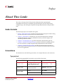
Preface
About This Guide
The CAN v3.2 Getting Started Guide provides information about generating the
LogiCORE™ IP CAN core, customizing and simulating the core with the provided
example design, and running the design files through implementation using the Xilinx
tools.
Guide Contents
The following chapters are included in this guide:
•
Preface, “About This Guide” introduces the organization and purpose of this Getting
Started Guide and the conventions used in this document.
•
Chapter 1, “Introduction” describes the core and related information, including
recommended design experience, additional resources, technical support, and
submitting feedback to Xilinx.
•
Chapter 2, “Licensing the Core” provides information about licensing the core.
•
Chapter 3, “Quick Start Example Design” provides instructions to quickly generate
the core and run the example design through implementation and simulation.
•
Chapter 4, “Detailed Example Design”describes the demonstration test bench in
detail and provides instructions for how to customize the demonstration test bench
for use in an application.
Conventions
This document uses the following conventions. An example illustrates each convention.
Typographical
The following typographical conventions are used in this document:
Convention
Meaning or Use
Example
Courier font
Messages, prompts, and
program files that the system
displays. Signal names also.
speed grade: - 100
Courier bold
Literal commands you enter in a
syntactical statement
ngdbuild design_name
Commands that you select from
a menu
File →Open
Keyboard shortcuts
Ctrl+C
Helvetica bold
CAN Getting Started Guide
UG186 April 19, 2010
www.xilinx.com
7
Preface: About This Guide
Convention
Meaning or Use
Example
Variables in a syntax statement
for which you must supply
values
ngdbuild design_name
References to other manuals
See the User Guide for details.
Emphasis in text
If a wire is drawn so that it
overlaps the pin of a symbol, the
two nets are not connected.
Dark Shading
Items that are not supported or
reserved
This feature is not supported
Square brackets
An optional entry or parameter.
However, in bus specifications,
such as bus[7:0], they are
required.
ngdbuild [option_name]
design_name
A list of items from which you
must choose one or more
lowpwr ={on|off}
Separates items in a list of
choices
lowpwr ={on|off}
User-defined variable or in code
samples
<directory name>
Vertical ellipsis
.
.
.
Repetitive material that has
been omitted
IOB #1: Name = QOUT’
IOB #2: Name = CLKIN’
.
.
.
Horizontal ellipsis . . .
Omitted repetitive material
allow block block_name loc1
loc2 ... locn;
The prefix ‘0x’ or the suffix ‘h’
indicate hexadecimal notation
A read of address 0x00112975
returned 45524943h.
An ‘_n’ means the signal is
active low
usr_teof_n is active low.
Italic font
Braces
[ ]
{ }
Vertical bar
|
Angle brackets < >
Notations
Online Document
The following linking conventions are used in this document:
Convention
8
Meaning or Use
Blue text
Cross-reference link to a
location in the current
document
Blue, underlined text
Hyperlink to a website (URL)
www.xilinx.com
Example
See the section “Guide
Contents” for details.
See “Title Formats” in Chapter 1
for details.
Go to www.xilinx.com for the
latest speed files.
CAN Getting Started Guide
UG186 April 19, 2010
Chapter 1
Introduction
The LogiCORE™ IP CAN v3.2 core is a compact, full-featured targeted design platform
that conforms to ISO 11898-1, CAN2.0A and CAN2.0B standards. Bit rates of up to 1 Mbps
are supported. The core size can be optimized using parameterized configurations for
acceptance filtering and FIFO depth. The example design in this guide is provided in both
Verilog and VHDL.
This chapter introduces the CAN core and provides related information, including system
requirements, recommended design experience, additional resources, technical support,
and submitting feedback to Xilinx.
About the Core
The CAN core is a Xilinx CORE Generator™ IP core, included in the latest IP Update on the
Xilinx IP Center. For detailed information about the core, see
www.xilinx.com/xlnx/xebiz/designResources/ip_product_details. For information
about licensing options, see Chapter 2, “Licensing the Core.”
System Requirements
Windows
•
Windows XP 2000 Professional 32-bit/64-bit
•
Windows Vista Business 32-bit/64-bit
•
Red Hat Enterprise Linux WS v4.0 32-bit/64-bit
•
Red Hat Enterprise Desktop v5.0 32-bit/64-bit (with Workstation Option)
•
SUSE Linux Enterprise (SLE) desktop and server v10.1 32-bit/64-bit
•
ISE® software v12.1
•
Mentor Graphics ModelSim v6.5c and above
•
Cadence Incisive Enterprise Simulator (IES) v9.2 and above
•
Synopsys VCS and VCS MX 2009.12 and above
Linux
Software
CAN Getting Started Guide
UG186 April 19, 2010
www.xilinx.com
9
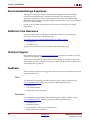
Chapter 1: Introduction
Recommended Design Experience
Although the CAN core is a fully-verified targeted design platform, the challenge
associated with implementing a complete CAN design varies, depending on the
application requirements. For best results, previous experience with building highperformance FPGA designs using Xilinx implementation software and a user constraints
file (UCF) is recommended.
Contact your local Xilinx representative for assistance in evaluating your specific
requirements.
Additional Core Resources
For detailed information and updates related to the CAN core, see the following
documents, located on the CAN product page:
www.xilinx.com/xlnx/xebiz/designResources/ip_product_details.
•
CAN Data Sheet
•
CAN Release Notes
Updates to this document are also available at the CAN product page.
Technical Support
For technical support, visit www.support.xilinx.com. Questions are routed to a team of
engineers with expertise using the CAN core.
Xilinx will provide technical support for use of this product as described in this guide.
Xilinx cannot guarantee timing, functionality, or support of this product for designs that
do not follow these guidelines.
Feedback
Xilinx welcomes comments and suggestions about the CAN core and the documentation
supplied with the core.
Core
For comments or suggestions about the CAN core, please submit a WebCase from
www.support.xilinx.com/. Be sure to include the following information:
•
Product name
•
Core version number
•
Explanation of your comments
Document
For comments or suggestions about this document, please submit a WebCase from
www.support.xilinx.com/. Be sure to include the following information:
10
•
Document title
•
Document number
•
Page number(s) to which your comments refer
•
Explanation of your comments
www.xilinx.com
CAN Getting Started Guide
UG186 April 19, 2010
Chapter 2
Licensing the Core
This chapter provides instructions for obtaining a license for the CAN core, which you
must do before using the core in your designs. The CAN core is provided under the terms
of the Xilinx LogiCORE Site License Agreement, which conforms to the terms of the
SignOnce IP License standard defined by the Common License Consortium. Purchase of
the core entitles you to technical support and access to updates for one year.
Before you Begin
This chapter assumes that you have installed all required software specified on the CAN
product page.
License Options
The CAN core provides three licensing options. After installing the required Xilinx ISE®
software and IP Service Packs, choose a license option.
Simulation Only
The Simulation Only Evaluation license key is provided with the Xilinx CORE Generator™
tool. This key lets you assess core functionality with either the example design provided
with the CAN core, or alongside your own design and demonstrates the various interfaces
to the core in simulation. (Functional simulation is supported by a dynamically generated
HDL structural model.)
Full System Hardware Evaluation
The Full System Hardware Evaluation license is available at no cost and lets you fully
integrate the core into an FPGA design, place-and-route the design, evaluate timing, and
perform functional simulation of the CAN core using the example design and
demonstration test bench provided with the core.
In addition, the license key lets you generate a bitstream from the placed and routed
design, which can then be downloaded to a supported device and tested in hardware. The
core can be tested in the target device for a limited time before timing out (ceasing to
function), at which time it can be reactivated by reconfiguring the device.
Cannot use this in production programs.
CAN Getting Started Guide
UG186 April 19, 2010
www.xilinx.com
11
Chapter 2: Licensing the Core
Full
The Full license key is available when you purchase the core and provides full access to all
core functionality both in simulation and in hardware, including:
•
Gate-level functional simulation support
•
Back annotated gate-level simulation support
•
Functional simulation support
•
Full-implementation support including place and route and bitstream generation
•
Full functionality in the programmed device with no time-outs
Obtaining Your License Key
This section contains information about obtaining a simulation, full system hardware, and
full license keys.
Simulation License
No action is required to obtain the Simulation Only Evaluation license key; it is provided
by default with the Xilinx CORE Generator software.
Full System Hardware Evaluation License
To obtain a Full System Hardware Evaluation license, do the following:
1.
Navigate to the CAN product page for this core.
2.
Click Evaluate.
3.
Follow the instructions to install the required Xilinx ISE software and IP Service Packs.
Obtaining a Full License
To obtain a Full license key, you must purchase a license for the core. After doing so, click
the “Access Core” link on the Xilinx.com IP core product page for further instructions.
Installing Your License File
The Simulation Only Evaluation license key is provided with the ISE CORE Generator
system and does not require installation of an additional license file. For the Full System
Hardware Evaluation license and the Full license, an email will be sent to you containing
instructions for installing your license file. Additional details about IP license key
installation can be found in the ISE Design Suite Installation, Licensing and Release Notes
document.
12
www.xilinx.com
CAN Getting Started Guide
UG186 April 19, 2010
Chapter 3
Quick Start Example Design
This chapter provides instructions to generate a CAN core quickly, run the design through
implementation with the Xilinx tools, and simulate the example design using the provided
demonstration test bench. See the example design in Chapter 4, “Detailed Example
Design.”
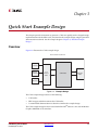
Overview
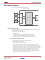
Figure 3-1 illustrates the CAN example design.
X-Ref Target - Figure 3-1
Demonstration Test Bench
CAN Example Design
Clock
Generator
Stimulus
Generator
User
Interface
IOBs
CAN Core
CAN Phy
IOBs
Checker
Figure 3-1:
Example Design
The CAN example design consists of the following:
•
CAN netlist
•
HDL wrapper which instantiates the CAN netlist
•
Customizeable demonstration test bench to simulate the example design
The CAN example design has been tested with Xilinx ISE® software v12.1 and the Mentor
Graphics ModelSim v6.5c simulator.
CAN Getting Started Guide
UG186 April 19, 2010
www.xilinx.com
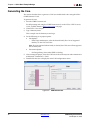
13
Chapter 3: Quick Start Example Design
Generating the Core
This section describes how to generate a CAN core with default values using the Xilinx
CORE Generator™ tool.
To generate the core:
1.
Start the CORE Generator tool.
For help starting and using the CORE Generator tool, see the Xilinx CORE Generator
Guide, available from the ISE documentation web page.
2.
Choose File > New Project.
3.
Type a directory name.
This example uses the directory name design.
4.
Do the following to set project options:
♦
Part Options
-
From Target Architecture, select the desired family. For a list of supported
families, see the CAN Data Sheet.
Note: If an unsupported silicon family is selected, the CAN core will not appear in
the taxonomy tree.
♦
Generation Options
-
For Design Entry, select either VHDL or Verilog.
5.
After creating the project, locate the CAN core in the taxonomy tree under Automotive
& Industrial >Automotive > CAN.
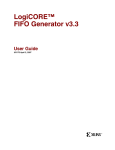
6.
Double-click the core to display the main CAN configuration screen.
X-Ref Target - Figure 3-2
Figure 3-2:
14
www.xilinx.com
CAN Main Screen
CAN Getting Started Guide
UG186 April 19, 2010
Implementing the Example Design
7.
In the Component Name field, enter a name for the core instance.
This example uses the name quickstart.
8.
After selecting the parameters from the GUI screens, click Finish.
The core and its supporting files, including the example design, are generated in the
project directory. For detailed information about the example design files and
directories see Chapter 4, “Detailed Example Design.”
Implementing the Example Design
After generating a core with either a Full-System Hardware Evaluation or Full license, the
netlists and example design can be processed by the Xilinx implementation tools. The
generated output files include scripts to assist you in running the Xilinx software.
To implement the CAN example design, open a command prompt or terminal window
and type the following commands:
For Windows:
ms-dos> cd <proj_dir>\quickstart\implement
ms-dos> implement.bat
For Linux:
Linux-shell% cd <proj_dir>/quickstart/implement
Linux-shell% ./implement.sh
These commands execute a script that synthesizes, builds, maps, and places-and-routes the
example design. The script then generates a post-par simulation model for use in timing
simulation. The resulting files are placed in the results directory.
Simulating the Example Design
The CAN core provides a quick way to simulate and observe the behavior of the core by
using the provided example design. There are two different simulation types: functional
and timing. The simulation models provided will either be in VHDL or Verilog, depending
on the CORE Generator software Design Entry project option.
Setting up for Simulation
The Xilinx UniSim and SimPrim libraries must be mapped into the simulator. If the UniSim
or SimPrim libraries are not set for your environment, go to the Synthesis and Simulation
Guide in the Xilinx Software Manuals for assistance compiling Xilinx simulation models.
Simulation scripts are provided for ModelSim.
CAN Getting Started Guide
UG186 April 19, 2010
www.xilinx.com
15
Chapter 3: Quick Start Example Design
Functional Simulation
This section provides instructions for running a functional simulation of the CAN core
using either VHDL or Verilog. Functional simulation models are provided when the core is
generated. Implementing the core before simulating the functional models is not required.
To run a VHDL or Verilog functional simulation of the example design:
1.
Set the current directory to:
<quickstart>/simulation/functional/
2.
Launch the simulation script.
ModelSim: vsim -do simulate_mti.do
ncsim (ms-dos>): simulate_ncsim.bat
ncsim (Linux-shell%): ./simulate_ncsim.sh
The simulation script compiles the functional simulation models and demonstration test
bench, adds relevant signals to the wave window, and runs the simulation. To observe the
operation of the core, inspect the simulation transcript and the waveform.
Timing Simulation
Timing simulation is supported only for the Full-System Hardware Evaluation and Full
license types, as the core cannot be implemented using a Simulation Only Evaluation
license. This section contains instructions for running a timing simulation of the CAN core
using either VHDL or Verilog. A timing simulation model is generated when the core is
run through the Xilinx tools using the implement script. It is a requirement that the core is
implemented before attempting to run timing simulation.
To run a VHDL or Verilog functional simulation of the example design:
1.
Set the current directory to:
<quickstart>/simulation/timing/
2.
Launch the simulation script:
ModelSim: vsim -do simulate_mti.do
ncsim (ms-dos>): simulate_ncsim.bat
ncsim (Linux-shell%): ./simulate_ncsim.sh
The simulation script compiles the timing simulation model and the demonstration test
bench, adds relevant signals to the wave window, and runs the simulation. To observe the
operation of the core, inspect the simulation transcript and the waveform.
16
www.xilinx.com
CAN Getting Started Guide
UG186 April 19, 2010
Chapter 4
Detailed Example Design
This chapter provides detailed information about the example design, including a
description of files and the directory structure generated by the Xilinx CORE Generator™
software, the purpose and contents of the provided scripts, the contents of the example
HDL wrappers, and the operation of the demonstration test bench.
top directory link - white text invisible
<project directory>
Top-level project directory; name is user-defined
topdirectory
<project_directory>/<component name>
Core release notes file
<component_name>/doc
Product documentation
<component_name>example design
Verilog and VHDL design files
<component_name>/implement
Implementation script files
<component_name>/implement/results
Results directory, created after implementation scripts are run, and
contains implement script results
<component_name>/simulation
Simulation scripts
<component_name>/simulation/functional
Functional simulation files
simulation/timing
Simulation files
CAN Getting Started Guide
UG186 April 19, 2010
www.xilinx.com
17
Chapter 4: Detailed Example Design
Directory and File Contents
The CAN v3.2 core directories and their associated files are defined in the following
sections.
<project directory>
The <project directory> contains all the CORE Generator software project files.
Table 4-1:
Project Directory
Name
Description
<project_dir>
<component_name>.ngc
Top-level netlist
<component_name>.v[hd]
Verilog or VHDL simulation model
<component_name>.xco
CORE Generator software projectspecific option file; can be used as an
input to the CORE Generator software.
<component_name>_flist.txt
List of files delivered with the core.
<component_name>.{veo|vho}
VHDL or Verilog instantiation
template.
Back to Top
<project_directory>/<component name>
The <component name> directory contains the release notes file provided with the core,
which may include last-minute changes and updates.
Table 4-2:
Component Name Directory
Name
Description
<project_dir>/<component_name>
can_release_notes.txt
Core name release notes file.
Back to Top
18
www.xilinx.com
CAN Getting Started Guide
UG186 April 19, 2010
Directory and File Contents
<component_name>example design
The example design directory contains the example design files provided with the core.
Table 4-3:
Example Design Directory
Name
Description
<project_dir>/<component_name>/example_design
<component_name>_top.ucf
Provides example constraints necessary for
processing the CAN core using the Xilinx
implementation tools.
<component_name>_top.v[hd]
The VHDL or Verilog top-level file for the
example design; it instantiates the CAN core.
<component_name>.v
Top-level file for the example design. Only
generated when Verilog design flow is
selected.
Back to Top
<component_name>/doc
The doc directory contains the PDF documentation provided with the core.
Table 4-4:
Doc Directory
Name
Description
<project_dir>/<component_name>/doc
can_ds265.pdf
CAN v3.2 Data Sheet
can_gsg186.pdf
CAN v3.2 Getting Started Guide
Back to Top
CAN Getting Started Guide
UG186 April 19, 2010
www.xilinx.com
19
Chapter 4: Detailed Example Design
<component_name>/implement
The implement directory contains the core implementation script files. Generated for FullSystem Hardware Evaluation and Full license types.
Table 4-5:
Implement Directory
Name
Description
<project_dir>/<component_name>/implement
implement.{bat|sh}
A Windows (.bat) or Linux script that
processes the example design.
xst.prj
The XST project file for the example design
that lists all of the source files to be
synthesized. Only available when the CORE
Generator software project option is set to
ISE® or Other.
xst.scr
The XST script file for the example design
used to synthesize the core. Only available
when the CORE Generator software Vendor
project option is set to ISE or Other.
Back to Top
<component_name>/implement/results
The results directory is created by the implement script, after which the implement script
results are placed in the results directory.
Table 4-6: Results Directory
Name
Description
<project_dir>/<component_name>/implement/results
Implement script result files.
Back to Top
<component_name>/simulation
The simulation directory contains the simulation scripts provided with the core.
Table 4-7: Simulation Directory
Name
Description
<project_dir>/<component_name>/simulation
glbl.v
Verilog test file provided with the
demonstration test bench.
can_v3_2_tb.v[hd]
Verilog/VHDL test file provided with the
demonstration test bench.
Back to Top
20
www.xilinx.com
CAN Getting Started Guide
UG186 April 19, 2010
Directory and File Contents
<component_name>/simulation/functional
The functional directory contains functional simulation scripts provided with the core.
Table 4-8: Functional Directory
Name
Description
<project_dir>/<component_name>/simulation/functional
simulate_mti.do
A macro file for ModelSim that compiles the
HDL sources and runs the simulation.
simulate_ncsim.sh
A macro file for Cadence IES that compiles
the HDL sources and runs the simulation in a
Linux environment.
simulate_ncsim.bat
A macro file for Cadence IES that compiles
the HDL sources and runs the simulation in a
Windows environment.
wave.do
A macro file for ModelSim that opens a wave
window and adds key signals to the wave
viewer. This file is called by the
simulate_mti.do file and is displayed after
the simulation is loaded.
wave.sv
A macro file for Cadence IES that opens a
wave window and adds key signals to the
wave viewer.
Back to Top
CAN Getting Started Guide
UG186 April 19, 2010
www.xilinx.com
21
Chapter 4: Detailed Example Design
simulation/timing
The timing simulation directory is generated only for Full-System Hardware Evaluation
and Full-license types.
Table 4-9:
Timing Directory
Name
Description
<project_dir>/<component_name>/simulation/timing
simulate_mti.do
A macro file for ModelSim that compiles the
post-par timing netlist, demonstration test
bench files, and runs the simulation.
simulate_ncsim.sh
A macro file for Cadence IES that compiles
the post-par timing netlist, demonstration
test bench files, and runs the simulation in a
Linux environment.
simulate_ncsim.bat
A macro file for Cadence IES that compiles
the post-par timing netlist, demonstration
test bench files, and runs the simulation in a
Windows environment.
wave.do
A macro file for ModelSim that opens a wave
window and adds key signals to the wave
viewer. This file is called by the
simulate_mti.do file and is displayed after
the simulation is loaded.
wave.sv
A macro file for Cadence IES that opens a
wave window and adds key signals to the
wave viewer.
Back to Top
22
www.xilinx.com
CAN Getting Started Guide
UG186 April 19, 2010
Implementation Scripts
Implementation Scripts
Note: Present only with a Full license.
The implementation script is either a shell script(.sh) or batch file (.bat) that processes the
example design through the Xilinx tool flow. It is located at:
Linux
<project_dir>/<component_name>/implement/implement.sh
Windows
<project_dir>/<component_name>/implement/implement.bat
When the CORE Generator software is run with the Full System Hardware Evaluation, or
Full license types, the implement script performs the following steps:
•
Synthesizes the HDL example design files using XST
•
Runs NGDBuild to consolidate the core netlist and the example design netlist into the
NGD file containing the entire design
•
Maps the design to the target technology
•
Place-and-routes the design on the target device
•
Performs static timing analysis on the routed design using Timing Analyzer (TRCE)
•
Generates a bitstream
•
Enables Netgen to run on the routed design to generate a VHDL or Verilog netlist (as
appropriate for the Design Entry project setting) and timing information in the form
of SDF files
The Xilinx tool flow generates several output and report files. These are saved in the
following directory which is created by the implement script:
<project_dir>/<component_name>/implement/results
Simulation Scripts
Functional Simulation
The test scripts are ModelSim macros that automate the simulation of the test bench. They
are available from the following location:
<project_dir>/<component_name>/simulation/functional/
The test script performs the following tasks:
•
Compiles the structural UniSim simulation model
•
Compiles HDL Example Design source code
•
Compiles the demonstration test bench
•
Starts a simulation of the test bench
•
Opens a Wave window and adds signals of interest (wave_mti.do/wave_ncsim.sv)
•
Runs the simulation to completion
CAN Getting Started Guide
UG186 April 19, 2010
www.xilinx.com
23
Chapter 4: Detailed Example Design
Timing Simulation
Note: Present only with a Full license.
The test scripts are a ModelSim or a Cadence IES macro that automates the simulation of
the test bench. They are located in:
<project_dir>/<component_name>/simulation/timing/
The test script performs the following tasks:
•
Compiles the SimPrim based gate level netlist simulation model
•
Compiles the demonstration test bench
•
Starts a simulation of the test bench
•
Opens a Wave window and adds signals of interest (wave_mti.do/wave_ncsim.sv)
•
Runs the simulation to completion
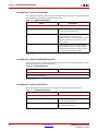
Example Design Configuration
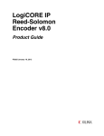
Figure 4-1 illustrates the example design configuration.
X-Ref Target - Figure 4-1
CAN Example Design
User
Interface
IOBs
CAN Core
CAN Phy
IOBs
Figure 4-1: Example Design Configuration
The example design contains the following:
•
An instance of the CAN core
During simulation, the CAN core is instantiated as a black box and replaced with the
CORE Generator software netlist during implementation and the gate-level simulation
model.
•
24
Input and output buffers for top-level port signal
www.xilinx.com
CAN Getting Started Guide
UG186 April 19, 2010
Demonstration Test Bench
Demonstration Test Bench
Figure 4-2 illustrates the demonstration test bench.
X-Ref Target - Figure 4-2
Demonstration Test Bench
CAN Example Design
Clock
Generator
Stimulus
Generator
User
Interface
IOBs
CAN Core
CAN Phy
IOBs
Checker
Figure 4-2:
Demonstration Test Bench
Test Bench Functionality
The demonstration test bench is a straightforward VHDL or Verilog file to exercise the
example design and the core itself.
The test bench consists of the following:
•
Clock Generators
•
Procedure to write to a Configuration Register memory location
•
Procedure to read from a Configuration Register memory location
•
Procedure to display the bits set in the Interrupt Status Register (ISR)
Core with No Acceptance Filtering
The demonstration test bench performs the following tasks:
•
Input clock signals are generated.
•
A reset is applied to the example design.
•
The Baud Rate Prescalar register and Bit Timing registers are written to. These
registers are read from and the values read are compared with the values written.
•
The Interrupt Enable Register is written to enable interrupts for TXBFLL and RXOK
bits. This register is read from and the value read is compared with the value written.
•
The Mode Select Register is written to select Loop Back mode of operation. This
register is read from and the value read is compared with the value written.
•
The Software Reset Register is written to enable CEN bit. This register is read from
and the value written is compared with the value read.
CAN Getting Started Guide
UG186 April 19, 2010
www.xilinx.com
25
Chapter 4: Detailed Example Design
•
Five messages are written in sequence:
1.
The first message is written to the TXHPB and is a standard data frame.
2.
The second message is written to the TX FIFO and is a standard data frame.
3.
The third message is written to the TX FIFO and is a standard remote frame.
4.
The fourth message is written to the TX FIFO and is an extended data frame.
5.
The fifth message is written to the TX FIFO and is an extended remote frame.
After each message is written, the test bench waits for the assertion of the interrupt
line. When the interrupt line is asserted, the following conditions occur:
♦
The bits set in the ISR are displayed.
♦
The RX FIFO is read if the RXOK bit is set. The message received is compared
with the message previously transmitted.
♦
The ICR is written to. This clears the bits in the ISR that are set.
With no acceptance filtering, all five messages are received in the RX FIFO.
Core with Acceptance Filtering
The demonstration test bench performs the following tasks:
•
Input clock signals are generated.
•
A reset is applied to the example design.
•
The Baud Rate Prescalar register and Bit Timing registers are written to. These
registers are read from and the values read are compared with the values written.
•
The Interrupt Enable Register is written to enable interrupts for TXBFLL and RXOK
bits. This register is read from and the value read is compared with the value written.
•
Acceptance Filter ID Register 1 and Acceptance Filter Mask Register 1 are written to.
These registers are read from and the values read are compared with the values
written.
•
The Acceptance Filter Register is written to enable Acceptance Filter pair 1. This
register is read from and the value read is compared with the value written.
•
The Mode Select Register is written to select Loop Back mode. This register is read
from and the value read is compared with the value written.
•
The Software Reset Register is written to enable CEN bit. This register is read from
and the value written is compared with the value read.
•
Five messages are written in a sequence.
1.
The first message is written to the TXHPB and is a standard data frame.
2.
The second message is written to the TX FIFO and is a standard data frame.
3.
The third message is written to the TX FIFO and is a standard remote frame.
4.
The fourth message is written to the TX FIFO and is an extended data frame.
5.
The fifth message is written to the TX FIFO and is an extended remote frame.
After each message is written, the test bench waits for the interrupt line to be asserted.
When the interrupt line is asserted, the following conditions occur:
26
♦
The bits in the ISR that are set are displayed.
♦
The RX FIFO is read if the RXOK bit is set. The message that is received is
compared with the message that was transmitted.
♦
The ICR is written to. This clears the bits in the ISR that are set.
www.xilinx.com
CAN Getting Started Guide
UG186 April 19, 2010
Demonstration Test Bench
•
After the fourth message is transmitted and received, the Interrupt Enable Register is
written to enable interrupts for TXOK, RXOK and TXBFLL. This register is read from
and the value read is compared with the value written.
•
The fifth message does not pass acceptance filtering. Only the TXOK bit in the ISR is
set when the ISR is asserted.
Customizing the Demonstration Test Bench
This section describes the variety of demonstration test bench customization options that
can be used for individual system requirements.
Changing the Data
You can change the contents of the message written to the TX FIFO / TX HPB by changing
the procedure call that writes to the TX FIFO and the TX HPB memory locations. The
relevant fields in the checkers must also be changed to ensure that the message read from
the RX FIFO matches the message that was transmitted.
Changing the CAN Parameters
The values written to the BRPR and the BTR registers can be changed for appropriate bit
timing values. The test bench operates in the Loop Back mode of operation.
Changing the Test Bench Structure
You can add messages using the following steps.
1.
Write the message to the TX FIFO.
2.
Wait for an interrupt and process the interrupt.
3.
Read the received message from the RX FIFO.
CAN Getting Started Guide
UG186 April 19, 2010
www.xilinx.com
27
Chapter 4: Detailed Example Design
28
www.xilinx.com
CAN Getting Started Guide
UG186 April 19, 2010