1
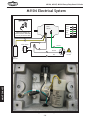
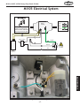
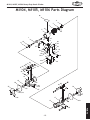
MODELS
M1104 M1105 M1106
HEAVY-DUTY BENCH
GRINDERS
M1106
M1105
M1104
OWNER'S MANUAL
Phone: 360-734-3482 • Online Technical Support: [email protected]
COPYRIGHT © APRIL, 2006 BY WOODSTOCK INTERNATIONAL, INC.
#8120CR
WARNING: NO PORTION OF THIS MANUAL MAY BE REPRODUCED IN ANY SHAPE OR FORM WITHOUT
THE WRITTEN APPROVAL OF WOODSTOCK INTERNATIONAL, INC.
Printed in China
�����������������������������������������������������������������������
��������������������������������������������������������������
����������������������������������������������������������������������
��������������������������������������������������������������������
������������������������
�����������������������������������������������������������������������
������������������������������������������������������������������������
�������������������������������������������������������������������
�����������������������������������������������������������������
����������������������������������������������������������������������
�����������������������������������������������
����������������������������������������������������������������
��������������������������������������������������������������������
�������
��������������������������������������������������������������������
�����������������������������������������������������������������������
����������������������������������������������������������������������
�������������������������������������
�� ����������������������������
�� ������������������������������������������������������������������
�� ����������������������������������������������������
������������������������������������������������������������������
������������������������������������������������������������������
��������������������������������������������������������������������
���������������������������������������������������������������������
��������������������������
SAFETY............................................................................................................3
Standard Safety Instructions ............................................................................. 3
Additional Safety Instructions for Grinders ............................................................ 5
OPERATIONS ................................................................................................... 11
General .....................................................................................................11
Grinding Operations ......................................................................................11
Wheel Selection ...........................................................................................12
Changing Grinding Wheels ...............................................................................13
PARTS
USE THE QUICK GUIDE PAGE LABELS TO SEARCH OUT INFORMATION FAST!
MAINTENANCE
PARTS ........................................................................................................... 19
Warranty ....................................................................................................22
Warranty Registration ....................................................................................23
OPERATIONS
MAINTENANCE ................................................................................................. 14
General .....................................................................................................14
Lubrication & Cleaning ..................................................................................14
Troubleshooting ...........................................................................................15
M1104 Electrical System .................................................................................16
M1105 Electrical System .................................................................................17
M1106 Electrical System .................................................................................18
M1104, M1105, M1106 Parts Diagram ..................................................................19
SET UP
SET UP ............................................................................................................7
Unpacking ................................................................................................... 7
Inventory .................................................................................................... 7
Shop Preparation ........................................................................................... 8
Mounting ..................................................................................................... 8
Tool Rest and Eye Shield.................................................................................. 9
Grinding Wheel Installation .............................................................................. 9
Test Run ....................................................................................................10
ELECTRICAL
ELECTRICAL ......................................................................................................6
110V Operation ............................................................................................. 6
Extension Cords ............................................................................................ 6
Grounding ................................................................................................... 6
SAFETY
INTRODUCTION ..................................................................................................2
Woodstock Technical Support ............................................................................ 2
Specifications ............................................................................................... 2
INTRODUCTION
Contents
INTRODUCTION
M1104, M1105, M1106 Heavy-Duty Bench Grinder
INTRODUCTION
Woodstock Technical Support
Your new SHOP FOX® Bench Grinder has been specially designed to provide many years of trouble-free
service. Close attention to detail, ruggedly built parts and a rigid quality control program assure safe
and reliable operation.
Woodstock International, Inc. is committed to customer satisfaction. Our intent with this manual is to
include the basic information for safety, setup, operation, maintenance, and service of this product.
We stand behind our machines! In the event that questions arise about your machine, please contact
Woodstock International Technical Support at (360) 734-3482 or send e-mail to: tech-support@shopfox.
biz. Our knowledgeable staff will help you troubleshoot problems and process warranty claims.
If you need the latest edition of this manual, you can download it from http://www.shopfox.biz.
If you have comments about this manual, please contact us at:
Woodstock International, Inc.
Attn: Technical Documentation Manager
P.O. Box 2309
Bellingham, WA 98227
M1104:
Specifications
Motor ...................................................... 1⁄2 HP, 110V, Single-Phase, 3450 RPM
Grinding Wheel Size, and Type ....................................... 6" X (1⁄2" to 3⁄4"), Type 1
Arbor Diameter ...................................................................................1⁄2"
Weight ...........................................................................................35 lbs
M1105:
Motor ...................................................... 3⁄4 HP, 110V, Single-Phase, 3450 RPM
Grinding Wheel Size, and Type ................................................... 8" X 1", Type 1
Arbor Diameter ...................................................................................5⁄8"
Weight .......................................................................................... 56 lbs
M1106:
Motor ..................................................... 11⁄2 HP, 110V, Single-Phase, 1725 RPM
Grinding Wheel Size, and Type ..................................................10" X 1", Type 1
Arbor Diameter .................................................................................... 1"
Weight ......................................................................................... 100 lbs
-2-
M1104, M1105, M1106 Heavy-Duty Bench Grinder
SAFETY
Indicates an imminently hazardous situation which, if not avoided, WILL
result in death or serious injury.
Indicates a potentially hazardous situation which, if not avoided, COULD
result in death or serious injury.
Indicates a potentially hazardous situation which, if not avoided, MAY
result in minor or moderate injury.
NOTICE
This symbol is used to alert the user to useful information about proper
operation of the equipment, and/or a situation that may cause damage
to the machinery.
Standard Safety Instructions
1. THOROUGHLY READ THE INSTRUCTION MANUAL BEFORE OPERATING YOUR MACHINE. Learn the
applications, limitations and potential hazards of this machine. Keep the manual in a safe and convenient place for future reference.
2. KEEP WORK AREA CLEAN AND WELL LIGHTED. Clutter and poor lighting invite potential hazards.
3. GROUND ALL TOOLS. If a machine is equipped with a three-prong plug, it must be plugged into a
three-hole grounded electrical receptacle or grounded extension cord. If using an adapter to aid in
accommodating a two-hole receptacle, ground using a screw to a known ground.
4. WEAR EYE PROTECTION AT ALL TIMES. Use safety glasses with side shields or safety goggles that
meet the appropriate standards of the American National Standards Institute (ANSI).
5. AVOID DANGEROUS ENVIRONMENTS. Do not operate this machine in wet or open flame environments. Airborne dust particles could cause an explosion and severe fire hazard.
6. ENSURE ALL GUARDS ARE SECURELY IN PLACE and in working condition.
7. MAKE SURE SWITCH IS IN THE OFF POSITION before connecting power to machine.
8. KEEP WORK AREA CLEAN, free of clutter, grease, etc.
9. KEEP CHILDREN AND VISITORS AWAY. Visitors must be kept at a safe distance while operating
unit.
10. CHILDPROOF YOUR WORKSHOP WITH PADLOCKS, master switches or by removing starter keys.
11. STOP AND DISCONNECT THE MACHINE WHEN CLEANING, ADJUSTING OR SERVICING.
-3-
SAFETY
READ MANUAL BEFORE OPERATING MACHINE.
FAILURE TO FOLLOW INSTRUCTIONS BELOW WILL
RESULT IN PERSONAL INJURY.
M1104, M1105, M1106 Heavy-Duty Bench Grinder
12. DO NOT FORCE TOOL. The machine will do a safer and better job at the rate for which it was
designed.
SAFETY
13. USE CORRECT TOOL. Do not force machine or attachment to do a job for which it was not
designed.
14. WEAR PROPER APPAREL. Do not wear loose clothing, neck ties, gloves, jewelry, and secure long
hair away from moving parts.
15. REMOVE ADJUSTING KEYS, RAGS, AND TOOLS. Before turning the machine on, make it a habit to
check that all adjusting keys and wrenches have been removed.
16. AVOID USING AN EXTENSION CORD. But if you must use one, examine the extension cord to ensure
it is in good condition. Immediately replace a damaged extension cord. Always use an extension
cord that uses a ground pin and connected ground wire. Use an extension cord that meets the amp
rating on the motor nameplate. If the motor is dual voltage, be sure to use the amp rating for the
voltage you will be using. If you use an extension cord with an undersized gauge or one that is too
long, excessive heat will be generated within the circuit, increasing the chance of a fire or damage
to the circuit.
17. KEEP PROPER FOOTING AND BALANCE at all times.
18. DO NOT LEAVE MACHINE UNATTENDED. Wait until it comes to a complete stop before leaving the
area.
19. PERFORM ALL MACHINE MAINTENANCE. Follow lubrication and accessory attachment instructions
in the manual.
20. KEEP MACHINE AWAY FROM OPEN FLAME. Operating machines near pilot lights or open flames
creates a high risk if dust is dispersed in the area. Dust particles and an ignition source may cause
an explosion. Do not operate the machine in high-risk areas, including but not limited to, those
mentioned above.
21. IF AT ANY TIME YOU ARE EXPERIENCING DIFFICULTIES performing the intended operation, stop
using the machine! Then contact our service department or ask a qualified expert how the operation should be performed.
22. HABITS—GOOD AND BAD—ARE HARD TO BREAK. Develop good habits in your shop and safety will
become second-nature to you.
-4-
M1104, M1105, M1106 Heavy-Duty Bench Grinder
Additional Safety Instructions for Grinders
USE this and other machinery with caution
and respect. Always consider safety first,
as it applies to your individual working
conditions. No list of safety guidelines can
be complete—every shop environment is
different. Failure to follow guidelines could
result in serious personal injury, damage
to equipment or poor work results.
1.
EYE PROTECTION. Grinding causes small particles to become airborne at a high rate of speed.
ALWAYS wear safety glasses when using this machine.
2.
MOUNTING TO BENCH/STAND. An unsecured grinder may become dangerously out of control during operation. Make sure grinder is FIRMLY secured to a bench/stand before use.
3.
WHEEL SPEED RATING. Wheels operated at a faster speed than rated for may break or fly apart.
Before mounting a new wheel, be sure the wheel RPM rating is equal or higher than the speed of
the grinder.
4.
WHEEL FLANGES. Only use the flanges included with the grinder when mounting wheels. Other
flanges may not properly secure the wheel and cause an accident.
5.
RING TEST. Perform a “ring test” on grinding wheels before installation to ensure that they are
safe to use. A wheel that does not pass the ring test may break or fly apart during operation.
6.
STARTING GRINDER. If a wheel IS damaged, it will usually fly apart shortly after start-up. To
protect yourself, always stand to the side of the grinder when turning it ON, allow it to gain full
speed and wait for at least 1 minute before standing in front of it.
7.
LUNG PROTECTION. Grinding produces hazardous dust, which may cause long-term respiratory
problems if breathed. Always wear a NIOSH approved dust mask or respirator when grinding.
8.
SIDE GRINDING. Grinding on the side of wheels can cause them to break and fly apart—unless the
wheel is rated for side grinding.
9.
TOP GRINDING. Grinding on the top of wheels greatly increases the risk of workpiece kickback.
Always grind on the downward part of the wheel.
10. HAND/WHEEL CONTACT. Grinding wheels have the capability of removing a lot of skin fast. Keep
a firm grip on the workpiece and position your hands a safe distance away when grinding. Avoid
wearing gloves as they may get caught in the grinding wheel and cause even more serious entanglement injuries.
11. TOOL REST POSITION. If the tool rest is too far away from the wheel, the workpiece may be
pulled down, causing loss of control and pulling your hand into the grinding wheel. Keep the tool
rest within 1⁄8" from the wheel when operating.
-5-
SAFETY
READ and understand this
entire instruction manual
before using this machine.
Serious personal injury
may occur if safety and
operational information is
not understood and followed. DO NOT risk your
safety by not reading!
M1104, M1105, M1106 Heavy-Duty Bench Grinder
ELECTRICAL
SAFETY
110V Operation
Your bench grinder needs a 110 volt power supply. When
choosing a power supply outlet for the Model M1104 and
M1105 bench grinder, use a circuit that is protected with
a 15 amp circuit breaker or fuse. For the Model M1106,
use a circuit that is protected with a 20 amp circuit
breaker or fuse. Keep in mind that a circuit being used
by other machines or tools at the same time will add to
the total load being applied to the circuit. Add up the
load ratings of all machines on the circuit. If this number
exceeds the rating of the circuit breaker or fuse, use a
different circuit.
Extension Cords
This equipment must be grounded.
Verify that any existing electrical outlet and circuit you intend to plug into
is actually grounded. If it is not, it
will be necessary to run a separate 12
AWG copper grounding wire from the
outlet to a known ground. Under no
circumstances should the grounding
pin from any three-pronged plug be
removed or serious injury may occur.
When it is necessary to use an extension cord, use the
following guidelines:
•
•
•
•
•
Use cords rated for Standard Service.
Never exceed a length of 50 feet.
Use cords with 14 ga. wire or bigger.
Insure cord has a ground wire and pin.
Do not use cords in need of repair.
Grounding
This grinder must be grounded! The electrical cord supplied comes with a grounding pin. Do not remove it (see
Figure 2). If your outlet does not accommodate a ground
pin, have it replaced by a qualified electrician or have
an appropriate adapter installed.
Note: When using an adapter, the adapter must be
grounded.
-6-
Figure 2. Never remove the grounding
pin!
M1104, M1105, M1106 Heavy-Duty Bench Grinder
SET UP
Unpacking
Your SHOP FOX® Bench Grinder has been carefully packaged for safe transporting. If you notice the
machine has been damaged, please contact your authorized SHOP FOX® dealer immediately.
NOTICE
If ordering replacement parts, refer to
the parts list and diagram in the back of
the manual.
Inventory
E
A
The following is a description of the main components
shipped with your bench grinder. Lay the components
out and use the list below and Figures 3 & 4 to inventory your package.
Box Inventory:
K
B
C
D
J
Qty.
If any parts are missing, examine the packaging for the
missing parts. For any missing parts, find the part number in the back of this manual and contact Woodstock
International, Inc. at (360) 734-3482 or at [email protected]
-7-
I
H
G
F
Figure 3. Left eye shield assembly.
L
M
N
Figure 4. Left tool rest and hardware.
SET UP
A. Left Lens Hanger (Eye Shield) ...........................1
Right Lens Hanger (Eye Shield) (Not Shown) ..........1
B. Toothed Flange Scr M6-1.25 x 13mm (Eye Shield) ...2
C. Lock Washer 7mm (Eye Shield) .........................2
D. Flat Washer 7mm (Eye Shield) ..........................2
E. Female Knob M6-1.25 (Eye Shield) .....................2
F. Hex Bolt M6-1.25 x 10mm (Eye Shield) ................4
G. Flat Washer 7mm (Eye Shield) ..........................4
H. Left Spark Arrestor (Eye Shield) ........................1
Right Spark Arrestor (Eye Shield) .......................1
I. Lens (Eye shield) (Not Shown)...........................2
J. Nut Plate (Eye Shield) ....................................2
K. Phlp Hd Scr #10-24 x 3⁄8" (Eye Shield) .................4
L. Left Tool Rest .............................................1
Right Tool Rest (Not Shown) .............................1
M. Flat Washer 8mm (Tool Rest) ...........................4
N. Hex Bolt 5⁄16"-18 x 3⁄4" (Tool Rest) ......................4
Heavy-Duty Bench Grinder Unit (Not Shown) .........1
M1104, M1105, M1106 Heavy-Duty Bench Grinder
Shop Preparation
•
Working Clearances: Consider existing and
anticipated needs, size of material to be processed
through the machine, and space for other machinery
when establishing a location for your new machine.
•
Lighting: Lighting should be bright enough to
eliminate shadow and prevent eye strain.
•
Electrical: Electrical circuits must be dedicated or
large enough to handle amperage requirements.
Outlets must be located near each machine, so
power or extension cords are clear of high-traffic
areas. Follow local electrical codes for proper
installation of new lighting, outlets, or circuits.
SET UP
Mounting
The Heavy-Duty Bench Grinder must be mounted to a
workbench to avoid accidental tipping. If you intend on
using the grinder for portable applications, mount it to
a heavy plywood base (at least 1" thick) that is wide
enough to prevent tipping or rocking during use, then
clamp the plywood base to the workbench or table.
MAKE your shop “child safe.” Ensure
that your workplace is inaccessible to
youngsters by closing and locking all
entrances when you are away. NEVER
allow untrained visitors in your shop
when assembling, adjusting or operating equipment.
A
To mount the Heavy-Duty Bench Grinder, do these
steps:
Holes are 5⁄16"
Diameter
1.
Determine the surface or object to which you will
mount your grinder, and obtain the needed hardware for your mounting application.
M1104: A = 6 5⁄16"
M1105: A = 7 5⁄16"
M1106: A = 8 3⁄4"
2.
Fasten the grinder to your supporting surface, using
the dimensions in Figure 5. DO NOT overtighten the
mounting bolts or you will crack the base.
3.
Check the stability of the mounted grinder to make
sure it is stable enough to be used safely.
4.
Always make sure the grinder is bolted or clamped
to the workbench, table, or grinder stand before
use.
-8-
Figure 5. Bench grinder mounting bolt
pattern.
M1104, M1105, M1106 Heavy-Duty Bench Grinder
Tool Rest and Eye Shield
The tool rest supports the workpiece during grinding.
Certain types of grinding may require jigs or accessories
to assure the proper angle of the workpiece against the
wheel.
The eye shield must be installed and positioned between
the grinding wheel and your face during grinding. The
eye shield is NOT a substitute for safety glasses or a
safety face shield. You must wear ANSI approved face
and eye protection.
Using the hardware from the Inventory list on Page
7, assemble the tool rests and eye shields as they are
shown in Figures 6 & 7.
Grinding Wheel
Installation
Always be sure to use a Type 1 wheel that is rated for
operating at 3450 RPM or greater for Models M1104/
M1105, and 1725 RPM or greater for the M1106. Install
the grinding wheel, paper disk, wheel flange, and nut in
the order shown in Figure 7, and then attach the side
cover.
Figure 6. Tool rest and eye shield
assembly.
NEVER assemble a grinding wheel on
the arbor without paper or fiber discs
between the wheel and the mounting flange. Omitting the discs can put
undue stress on the wheel, causing it
to crack and possibly fly apart.
Note: The arbor shaft and nut on the left-hand side of
the grinder is a left-hand thread, so tightening it will
require turning it counterclockwise.
-9-
Figure 7. Grinding wheel installation
order.
SET UP
Before installing the included grinding wheels, you must
check them for integrity by performing a “ring test.”
Hang on a string, then lightly tap the rim of the wheel
with a piece of wood such as the handle of a hammer.
The wheel should have a ringing or harmonic type of
sound. If the wheel responds with a dull thud it may
indicate that the wheel has cracks. Do not use a wheel
which is suspected of having cracks, or if there are visual chips, nicks or dents in the wheel surface. This damage can lead to wheel failure, causing the wheel to fly
apart at operating speed.
M1104, M1105, M1106 Heavy-Duty Bench Grinder
Test Run
Once your machine is mounted and assembled, you should
perform a test run to make sure it works properly.
To perform a test run, do these steps:
1.
Make sure all tools are removed from the grinder
area.
2.
Make sure the switch is in the OFF position.
3.
Plug the grinder into the power source.
4.
Turn the grinder ON. Under normal conditions, the
grinder will make a humming noise, with only minor
vibration.
SET UP
— If you suspect any problems, immediately turn
the grinder OFF and refer to Page 15 to troubleshoot and correct any problems before starting the
grinder again.
— If the source of an unusual noise or vibration is not
readily apparent, contact our technical support
for help at (360) 734-3482 or contact us online at
[email protected].
-10-
DO NOT investigate problems or adjust
the Heavy-Duty Bench Grinder while
it is running. Wait until the machine
is turned OFF, unplugged and the
spindle has come to a complete stop
before proceeding!
M1104, M1105, M1106 Heavy-Duty Bench Grinder
OPERATIONS
General
Your bench grinder will allow you to perform many types
of grinding and buffing operations. However, the following section is not a complete guide for every possible
use.
We strongly recommend that you read books, trade magazines, or seek formal training before attempting any
grinding or buffing operations in which you are not confident with. Above all, your safety should come first.
This recommended research will pay off with increased
safety, improved work results, and the knowledge to be
a better metalworker.
Grinding Operations
NEVER grind non ferrous metals like aluminum,
brass, copper, bronze, and others, or the grinding
wheel will load up, overheat, and can explode during operation.
When mounting a new wheel, or when there is any
concern about wheel integrity, stand away from the line
of rotation of the wheel and then turn the grinder ON.
Allow the grinder operate for one minute. If there is a
problem it will generally occur when the grinder is first
started. If the grinding wheel is OK, rest the workpiece
on the tool rest and ease the workpiece into the grinding
wheel. Begin grinding without holding the workpiece in
one spot or it will cause uneven wear on the stone face.
-11-
DO NOT make adjustments while the
grinder is running. Ensure that the
switch is OFF, power is disconnected
and moving parts have stopped before
making adjustments. Failure to comply
could result in serious injury or
electrical shock hazard.
OPERATIONS
Once the assembly and the test run have been
completed, your Heavy-Duty Bench Grinder is ready for
use.
Operation of this equipment has the
potential to propel debris into the air
which can cause eye injury. Always
wear safety glasses or goggles when
operating a grinder. Everyday glasses
or reading glasses are not safety glasses. Be certain the safety glasses you
wear meet the appropriate standards
of the American National Standards
Institute (ANSI).
M1104, M1105, M1106 Heavy-Duty Bench Grinder
Wheel Selection
Aluminum oxide and silicon carbide wheels are
marked in a somewhat uniform manner by all the
major manufacturers. Understanding these markings
will help you understand the capabilities of various
wheels. Always refer to the manufacturer’s grinding
recommendations when selecting a wheel for your
project.
The basic format for wheel numbering is:
Prefix�Type Abrasive�Type Grit�Type Grade Bond�Type
36
A
60
L
V
The most common abrasive types used are A for
Aluminum Oxide and C for Silicon Carbide, and
occasionally SG for seeded gel. The prefix is the
manufacturer’s designation for a particular type.
The grit size is a number referring to the size of the
abrasive grain in the wheel. The lower the number
the coarser the wheel—10 is a very coarse wheel for
roughing and 220 is usually the upper range for fine
finish work.
OPERATIONS
Grade is an indication of the hardness of the wheel, with
A being softest to Z the hardest.
Bond type refers to the type of bonding material used to
hold the abrasive material. Most general purpose wheels
will have a V indicating vitrified clay is used, providing a
high strength and good porosity. The other most common
is B for resin where synthetic resins are used. These are
used to grind cemented carbide and ceramic materials.
There may be other numbers inserted that have
meaning for a particular type of wheel. Refer to
the manufacturer’s technical data for a complete
explanation.
-12-
DO NOT use this grinder with a liquid
cooling system required for wet grinding wheel operations. Ignoring this
warning can lead to electrocution.
M1104, M1105, M1106 Heavy-Duty Bench Grinder
Changing Grinding
Wheels
Before installing any grinding wheel you must check the
structural integrity by performing a “ring test.” Hang the
wheel on a string, then lightly tap the rim of the wheel
with a piece of wood such as the handle of a hammer.
The wheel should have a ringing or harmonic type of
sound. If the wheel responds with a dull thud it may
indicate that the wheel has cracks. Do not use a wheel
that is suspected of having cracks, or if there are visual
chips, nicks or dents in the wheel surface. This damage
can lead to wheel failure, causing the wheel to fly apart
at operating speed.
Do not use a wheel that is suspected of having cracks,
or if there are visual chips, nicks or dents in the wheel
surface. This damage can lead to wheel failure where
the wheel flies apart at operating speed. Always be sure
to use a wheel which is rated for 3450 RPM or greater.
To change a grinding wheel, do these steps:
1.
DISCONNECT THE GRINDER FROM POWER!
2.
Disassemble grinder to the level shown in Figure 8.
3.
Hold the wheel from turning, and remove the arbor
nut which holds the wheel on.
4.
Install the new wheel in the order shown in Figure
8 and tighten the arbor nut snugly, but do not over
tighten or you will crack the wheel.
5.
Run a new wheel for at least 1 minute while standing clear of the line of rotation. If a wheel does
have defects it will generally fail as soon as it gets
up to full speed.
-13-
NEVER assemble a grinding wheel on
the arbor without paper or fiber discs
between the wheel and the flange.
Omitting the discs can put uneven
stress on the wheel causing it to crack
and possibly fly apart. ALWAYS “ring
test” a wheel before assembly to make
certain it has no cracks or flaws.
OPERATIONS
Note: The arbor shaft and nut on the left hand side
of the grinder is a left hand thread, so loosening it
will require turning it clockwise.
Figure 8. Grinding wheel access.
M1104, M1105, M1106 Heavy-Duty Bench Grinder
MAINTENANCE
General
Check for the following conditions and repair or
replace when necessary:
•
•
•
•
•
Cracked or loose grinding wheel.
Loose mounting bolts.
Worn switch.
Worn or damaged cords and plugs.
Any other condition that could hamper the safe
operation of this machine.
Lubrication & Cleaning
This grinder has sealed bearings that require no user
lubrication.
The grinding wheel should be inspected before every
use. Use the ring test method noted in Changing
Grinding Wheels on Page 13 to verify the structural
integrity. Take care in storing grinding wheels to keep
them free from potential damage by being dropped, or
having other items drop on them.
MAINTENANCE
Replace the wheel when the wheel diameter is reduced
to 4" for the M1104, 5" for the M1105, or 6 1⁄2" for the
M1106. Operating at anything less than this diameter
does not allow the proper surface speed for grinding
or spacing of the tool rest and the eye shield, and the
grinding wheel may fly apart.
Depending on the type of grinding you do, the grinding
wheel may require periodic dressing. There are several
different types of wheel dressing devices available on
the market. Use a suitable diamond or silicon carbide
stick type dresser. Sweep it smoothly and evenly several
times across the face of the wheel. Dressing restores the
abrasive quality of the wheel surface, plus it will bring
the wheel edge back to a square form. Refer to the
instructions that accompany your dressing accessory for
complete detail on wheel dressing.
-14-
MAKE SURE that your machine is
unplugged during all maintenance procedures! If this warning is ignored, serious personal injury may occur.
M1104, M1105, M1106 Heavy-Duty Bench Grinder
Troubleshooting
This section covers the most common problems and corrections with this type of
machine. WARNING! DO NOT make any adjustments until power is disconnected and
moving parts have come to a complete stop!
PROBLEM
POSSIBLE CAUSE
CORRECTIVE ACTION
Motor will not start; fuses
or circuit breakers blow.
1. Open circuit in motor or loose
connections.
2. Start capacitor is at fault.
3. Short circuit in motor or loose
connections.
4. Incorrect fuses or circuit breakers
in power supply.
1. Inspect/repair all lead connections on motor for loose or open
connections.
2. Replace start capacitor.
3. Inspect all connections on motor for loose or shorted terminals or
worn insulation.
4. Install correct fuses or circuit breakers.
Motor overheats, stalls
(resulting in blown fuses or
tripped circuit).
1. Motor overloaded.
1. Reduce load on motor.
2. Short circuit in motor or loose
connections.
2. Inspect connections on motor for loose or shorted terminals or
worn insulation.
3. Depth of cut too great.
3. Slow down the rate of movement of the workpiece into wheel.
1. Machine vibrating.
2. Workpiece is not held in place
firmly.
3. Wheel face uneven.
4. Wheel is too hard.
1. Make sure machine is securely mounted on a solid surface.
2. Use a holding device to firmly retain the workpiece.
Lines on surface of
workpiece.
1. Impurity on wheel surface.
2. Workpiece not being held tightly.
1. Dress the grinding wheel.
2. Use a holding device to firmly retain the workpiece.
Burning spots or cracks in
the workpiece.
1. Improper type of grinding wheel.
2. Improper feed rate.
1. Try a wheel that is softer style or a coarser grit.
2. Slow down the rate of movement of the workpiece into wheel.
1. Depth of cut too great.
2. Wheel is too soft.
1. Slow down the rate of movement of the workpiece into wheel.
2. Wheel too soft for the material being ground, select harder
bond.
3. Replace the wheel.
4. Dress the wheel.
5. Consult manufacturer of grinding wheel.
Wavy condition on surface
of workpiece.
Wheel dulls quickly, grit
falls off.
3. Wheel diameter too small.
4. Bad wheel dress.
5. Defective wheel bonding.
Wheel clogs and workpiece
shows burn marks.
1. Wheel is too hard.
2. Feed rate too slow.
3. Bad wheel dress.
4. Wrong material is being ground.
3. Dress the grinding wheel.
4. Use softer wheel, or reduce the feed rate.
1. Wheel too hard for the material being ground, select softer
bond.
2. Increase the rate of movement of the workpiece into wheel.
3. Dress the wheel.
4. Grind ferrious metals only.
MAINTENANCE
-15-
M1104, M1105, M1106 Heavy-Duty Bench Grinder
M1104 Electrical System
���������
������
�������
��������������������������
�����������������������
���������������������������
������������������������
�����
��
�����
��
�����
��
����
��
������
��
��
��
��
������������
��
������
��
��
��
�������
���
MAINTENANCE
������
���������
Figure 9. M1104 Wiring.
-16-
���������
�������
M1104, M1105, M1106 Heavy-Duty Bench Grinder
M1105 Electrical System
���������
������
�������
�����
��������������������������
�����������������������
���������������������������
������������������������
��
�����
��
�����
��
������
��
��
��
��
������������
��
������
��
��
��
�������
���
���������
�������
������
���������
MAINTENANCE
Figure 10. M1105 Wiring.
-17-
M1104, M1105, M1106 Heavy-Duty Bench Grinder
M1106 Electrical System
���������
������
�������
�����
��������������������������
�����������������������
���������������������������
������������������������
��
��
�����
��
����
��
������
��
���
��
������������
���������������
��
��
��
��
��
��
��
������
��
��
MAINTENANCE
��
�������
���
Figure 11. M1106 Wiring.
-18-
��
�����
���������
�������
M1104, M1105, M1106 Heavy-Duty Bench Grinder
M1104, M1105, M1106 Parts Diagram
��
��
�
�
��
�
��
�
��
��
�
��
��
��
��
�
��
��
��
�
��
�
��
��
��
��
��
��
��
�
��
��
��
��
��
���
�
��
��
��
�
��
�� ��
��
��
��
��
��
��
��
��
��
��
��
��
��
��
��
��
��
��
��
��
��
-19-
PARTS
��
M1104, M1105, M1106 Heavy-Duty Bench Grinder
REF
1
2
3
4
5
6
7
8
9
10
11
12
13
14
15
16
17
18
19
20
21
XM1104001
XM1105001
XM1106001
XPS06
XM1104003
XM1105003
XM1106003
XM1104004
XM1104005
XM1105005
XM1106005
XM1104006
XM1105006
XM1106006
XPSS07
XPW06
XPN05
XM1104010
XM1105010
XM1106010
XP6202
XP6204
XP6206
XM1104012
XM1105012
XM1106012
XM1104013
XM1105013
XM1106013
XM1104014
XM1105014
XM1106014
XPS22
XM1104016
XM1105016
XM1106016
XM1104017
XM1105017
XM1106017
XPS04
XM1104019
XM1105019
XM1106019
XM1104020
XM1105020
XM1106020
XM1104021
XM1105021
XM1106021
XM1104022
XM1105022
XM1106022
DESCRIPTION
REF
ROTOR�AND�SHAFT�(M1104)
ROTOR�AND�SHAFT�(M1105)
ROTOR�AND�SHAFT�(M1106)
PHLP�HD�SCR�10-24�X�3/8
STATOR�(M1104)
STATOR�(M1105)
STATOR�(M1106)
STRAIN�RELIEF
MOTOR�HOUSING�(M1104)
MOTOR�HOUSING�(M1105)
MOTOR�HOUSING�(M1106)
BASE�(M1104)
BASE�(M1105)
BASE�(M1106)
SET�SCREW�1/4-20�X�1/2
FLAT�WASHER�1/4
HEX�NUT�1/4-20
FAN��(M1104)
FAN��(M1105)
FAN��(M1106)
BALL�BEARING�6202ZZ�(M1104)
BALL�BEARING�6204ZZ�(M1105)
BALL�BEARING�6206ZZ�(M1106)
MOTOR�COVER�(M1104)
MOTOR�COVER�(M1105)
MOTOR�COVER�(M1106)
CENTRIFUGAL�SWITCH�ASSY.�(M1104)
CENTRIFUGAL�SWITCH�ASSY.�(M1105)
CENTRIFUGAL�SWITCH�ASSY.�(M1106)
CENTRIFUGAL�SWITCH�PLATE�(M1104)
CENTRIFUGAL�SWITCH�PLATE�(M1105)
CENTRIFUGAL�SWITCH�PLATE�(M1106)
PHLP�HD�SCR�10-24�X�5/8
LEFT�INNER�WHEEL�GUARD�(M1104)
LEFT�INNER�WHEEL�GUARD�(M1105)
LEFT�INNER�WHEEL�GUARD�(M1106)
RIGHT�INNER�WHEEL�GUARD�(M1104)
RIGHT�INNER�WHEEL�GUARD�(M1105)
RIGHT�INNER�WHEEL�GUARD�(M1106)
PHLP�HD�SCR�1/4-20�X�1/2
1/2"�WHEEL�FLANGE��(M1104)
5/8"�WHEEL�FLANGE��(M1105)
1"�WHEEL�FLANGE��(M1106)
1/2"�BORE�A36�GRINDING�WHEEL�(M1104)
5/8"�BORE�A36�GRINDING�WHEEL�(M1105)
1"�BORE�A36�GRINDING�WHEEL�(M1106)
1/2"�BORE�A60�GRINDING�WHEEL�(M1104)
5/8"�BORE�A60�GRINDING�WHEEL�(M1105)
1"�BORE�A60�GRINDING�WHEEL�(M1106)
LEFT�1/2"�ARBOR�NUT�(M1104)
LEFT�5/8"�ARBOR�NUT�(M1105)
LEFT�1"�ARBOR�NUT�(M1106)
23
PARTS
22
PART�#
-20-
24
25
26
27
28
29
30
31
32
33
34
35
36
37
38
39
40
41
42
43
44
45
46
47
48
49
PART�#
XM1104023
XM1105023
XM1106023
XM1104024
XM1105024
XM1106024
XM1104025
XM1105025
XM1106025
XPS04
XM1104027
XM1105027
XM1106027
XM1104028
XM1105028
XM1106028
XPW07
XPB07
XM1104031
XM1104032
XPS18
XPC100
XPC200
XPC300S
XM1104035
XM1106035
XM1104036
XM1106036
XM1104037
XPS18
XM1104039
XPLW01M
XM1104041
XM1105041
XM1104042
XM1105042
XM1104043
XM1105043
XM1106043
XM1104044
XM1105044
XM1106044
XM1104045
XM1104046
XM1106046
XM1104047
XM1106047
XM1104048
XM1106048
XM1104049
XM1106049
DESCRIPTION
RIGHT�1/2"�ARBOR�NUT�(M1104)
RIGHT�5/8"�ARBOR�NUT�(M1105)
RIGHT�1"�ARBOR�NUT�(M1106)
RIGHT�OUTER�WHEEL�GUARD�(M1104)
RIGHT�OUTER�WHEEL�GUARD�(M1105)
RIGHT�OUTER�WHEEL�GUARD�(M1106)
LEFT�OUTER�WHEEL�GUARD�(M1104)
LEFT�OUTER�WHEEL�GUARD�(M1105)
LEFT�OUTER�WHEEL�GUARD�(M1106)
PHLP�HD�SCR�1/4-20�X�1/2
LEFT�TOOL�REST�(M1104)
LEFT�TOOL�REST�(M1105)
LEFT�TOOL�REST�(M1106)
RIGHT�TOOL�REST�(M1104)
RIGHT�TOOL�REST�(M1105)
RIGHT�TOOL�REST�(M1106)
FLAT�WASHER�5/16
HEX�BOLT�5/16-18�X�3/4
STRAIN�RELIEF
WIRE�PLATE
PHLP�HD�SCR�10-24�X�1/4
CAPACITOR�100MFD�125V�(M1104)
CAPACITOR�200MFD�125V�(M1105)
CAPACITOR�300MFD�125V�(M1106)
FIXTURE�CLIP�(M1104/M1105)
FIXTURE�CLIP�(M1106)
CAPACITOR�CAP�(M1104/M1105)
CAPACITOR�CAP�(M1106)
POWER�CORD�110V
PHLP�HD�SCR�10-24�X�1/4
COPPER�WASHER�5MM
LOCK�WASHER�5MM
ROCKER�SWITCH�(M1104)
TOGGLE�SWITCH�RF-1001
(M1105/M1106)
SWITCH�PLATE�(M1104)
SWITCH�PLATE�(M1105/M1106)
BASE�PLATE�(M1104)
BASE�PLATE�(M1105)
BASE�PLATE�(M1106)
RUBBER�FOOT�(M1104)
RUBBER�FOOT�(M1105)
RUBBER�FOOT�(M1106)
ARROW�LABEL�
RIGHT�SPARK�ARRSTR�(M1104/M1105)
RIGHT�SPARK�ARRSTR�(M1106)
LEFT�SPARK�ARRSTR�(M1104/M1105)
LEFT�SPARK�ARRSTR�(M1106)
RIGHT�BRACKET�(M1104/M1105)
RIGHT�BRACKET�(M1106)
LEFT�BRACKET�(M1104/M1105)
LEFT�BRACKET�(M1106)
M1104, M1105, M1106 Heavy-Duty Bench Grinder
REF
50
PART�#
51
52
53
XM1104050
XM1105050
XM1106050
XM1104051
XPB51
XPS18
54
XPS04
XM1104054
DESCRIPTION
REF
EYESHIELD�(M1104)
EYESHIELD�(M1105)
EYESHIELD�(M1106)
NUTPLATE
HEX�BOLT�1/4-20�X�3/8
PHLP�HD�SCR�10-24�X�1/4
(M1104/M1105)
PHLP�HD�SCR�1/4-20�X�1/2�(M1106)
FEMALE�KNOB�1/4-20
55
56
57
59
60
PART�#
XPS06
XPLW02
XPS04
XM1104059
XM1105059
XM1106059
XPW02M
XPW06
DESCRIPTION
PHLP�HD�SCR�10-24�X�3/8
LOCK�WASHER�1/4
PHLP�HD�SCR�1/4-20�X�1/2
DATA/WARNING�LABEL�(M1104)
DATA/WARNING�LABEL�(M1105)
DATA/WARNING�LABEL�(M1106)
FLAT�WASHER�5MM�(M1104/1105)
FLAT�WASHER�1/4�(M1106)
PARTS
-21-
Warranty
Woodstock International, Inc. warrants all SHOP FOX® machinery to be free of defects from workmanship and materials for a period of two years from the date of original purchase by the original
owner. This warranty does not apply to defects due directly or indirectly to misuse, abuse, negligence
or accidents, lack of maintenance, or reimbursement of third party expenses incurred.
Woodstock International, Inc. will repair or replace, at its expense and at its option, the SHOP FOX®
machine or machine part which in normal use has proven to be defective, provided that the original
owner returns the product prepaid to the SHOP FOX® factory service center or authorized repair
facility designated by our Bellingham, WA office, with proof of their purchase of the product within
two years, and provides Woodstock International, Inc. reasonable opportunity to verify the alleged
defect through inspection. If it is determined there is no defect, or that the defect resulted from
causes not within the scope of Woodstock International Inc.'s warranty, then the original owner must
bear the cost of storing and returning the product.
This is Woodstock International, Inc.'s sole written warranty and any and all warranties that may be
implied by law, including any merchantability or fitness, for any particular purpose, are hereby limited
to the duration of this written warranty. We do not warrant that SHOP FOX® machinery complies
with the provisions of any law or acts. In no event shall Woodstock International, Inc.'s liability under
this warranty exceed the purchase price paid for the product, and any legal actions brought against
Woodstock International, Inc. shall be tried in the State of Washington, County of Whatcom. We shall
in no event be liable for death, injuries to persons or property or for incidental, contingent, special or
consequential damages arising from the use of our products.
Every effort has been made to ensure that all SHOP FOX® machinery meets high quality and durability standards. We reserve the right to change specifications at any time because of our commitment to
continuously improve the quality of our products.
Warranty Registration
Name ___________________________________________________________________________________
Street __________________________________________________________________________________
City _________________________ State ___________________________Zip ________________________
Phone # ______________________ Email __________________________Invoice # ___________________
Model #_________Serial #______________Dealer Name__________________Purchase Date___________
CUT ALONG DOTTED LINE
The following information is given on a voluntary basis. It will be used for marketing purposes to help us
develop better products and services. Of course, all information is strictly confidential.
1.
How did you learn about us?
_____ Advertisement
_____ Mail Order Catalog
2.
How long have you been a woodworker/metalworker?
_____ 0-2 Years
_____ 2-8 Years
____ 8-20 Years
_____ 20+ Years
3.
How many of your machines or tools are Shop Fox®?
_____ 0-2
_____ 3-5
____ 6-9
_____ 10+
4.
Do you think your machine represents a good value?
_____ Yes
____ No
5.
Would you recommend Shop Fox® products to a friend? _____ Yes
____ No
6.
What is your age group?
_____ 20-29
_____ 50-59
7.
What is your annual household income?
_____ $20,000-$29,000
____ $30,000-$39,000
_____ $50,000-$59,000
____ $60,000-$69,000
8.
Which of the following magazines do you subscribe to?
____
____
____
____
____
____
____
____
____
____
9.
Cabinet Maker
Family Handyman
Hand Loader
Handy
Home Shop Machinist
Journal of Light Cont.
Live Steam
Model Airplane News
Modeltec
Old House Journal
____ Friend
____ Website
____ Local Store
____ Other:
____ 30-39
____ 60-69
____
____
____
____
____
____
____
____
____
____
Popular Mechanics
Popular Science
Popular Woodworking
Practical Homeowner
Precision Shooter
Projects in Metal
RC Modeler
Rifle
Shop Notes
Shotgun News
____ 40-49
____ 70+
____ $40,000-$49,000
____ $70,000+
____
____
____
____
____
____
____
____
____
Today’s Homeowner
Wood
Wooden Boat
Woodshop News
Woodsmith
Woodwork
Woodworker West
Woodworker’s Journal
Other:
Comments:__________________________________________________________________
_____________________________________________________________________________
_____________________________________________________________________________
_____________________________________________________________________________
FOLD ALONG DOTTED LINE
Place
Stamp
Here
WOODSTOCK INTERNATIONAL INC.
P.O. BOX 2309
BELLINGHAM, WA 98227-2309
FOLD ALONG DOTTED LINE
TAPE ALONG EDGES--PLEASE DO NOT STAPLE