1
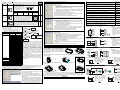
STEP 1: Setting M1184=On on PLC side (start-up MODEM)
STEP 2: Setting M1185=On (start-up PLC’s MODEM initialization)
STEP 3: Check the result of MODEM initialization: M1186=On means succeed to initial. M1187=On
means fail to initial.
STEP 4: After initialing successful, WPL software can be ready for connection on remote PC side. WPL
connection method: setting -> modem connection (you need to install modem’s driver first) -> to
get dial connection dialog box and then fill in dial information as following.
http://www.delta.com.tw/products/plc.asp
DVP-EH
Function Card
If you dial a number to access an outside line, what is it? Please fill in this
field when it is necessary.
Telephone number: if there is any area code or city code, you don’t need
to put anything for distinction. Only key the figure one by one directly.
For example: 88633626301
Instruction Sheet
1
This instruction provides electrical specification, function specification, wiring and basic program
design. For detail program design and instruction explanation information refer to PLC Application
Manual (programming).
power off and have static
electricity protection, such as wear antistatic gloves, to avoid damage those components on
Thank you for choosing DELTA’s PLC extension card of DVP-EP/EH Series. There are analog
memory card. Refer to following table for detail.
Outline
Terminal Layout (DB-9
male)
GND
V. High
Tx
Rx
After dialing connection successfully, dial connection dialog box will disappear automatically. Now,
you can monitor remote PLC via WPL. If there is remote control signal detected on PLC side, M1188
will be On and user can know if PLC is monitored by remote control via this special M.
5
9
4
7
2
MPU built in COM1(RS-232) and COM2(RS-485).
When connecting RS-232 to PC or other peripheral,
such as MODEM, by using COM2, you can use this
extension card. The communication function is the
same as COM2 except communication interface, i.e.
there are Slave mode and Master mode for you to
choose. Note: PLC will set that COM2 is occupied by
RS-232 card and built-in COM2 (RS-232) function will
be invalid after inserting this card. Refer to following for
system connection.
RS-485 is invalid
V. High
6
1
Applicable
Model
EP
EH
Function Explanation
PC
8
3
○
or
V. High: high potential, i.e. logic 1
Note:
Please pay attention for
pin 2 and pin 3 when
connecting this
communication port to
PC or HMI.
(RS-232)
○
DVP EP/EH MPU
extension card for
communication port
DVP-F232 or DVP-F422
select one Master/Slave device
HMI
Device
Function Explanation
Remark
M1184 Start-up MODEM
When M1184=On, following actions are valid.
M1185 Start-up MODEM initialization
This flag will be Off after finishing initialization.
M1186 Fail to initial MODEM
When M1185=On, M1186=Off.
M1187 Succeed to initial MODEM
When M1185=On,M1187=Off.
M1188 Display if MODEM is connected or not On means in connection
4. Additional explanation on PLC side:
a) It must use with RS-232 card when connecting MODEM on PLC side. If not, above special M
are invalid.
b) You must set M1185=On to initial MODEM after MODEM start-up (M1184=On). If not, it can’t
start-up MODEM auto dial function on PLC side.
c) MODEM will enter auto dial mode after initialization.
d) MODEM will enter to ready for dial mode on PLC side after remote PC stops connection. If user
turn MODEM power off now, it should need to initial at the next time when turning on MODEM.
e) The initial format that used to MODEM on PLC side are ATZ and ATS0=1.
User can use COM2 to connect RS-422 and HMI or other
DVP-F422
peripheral for long distance connection. The communication
(RS-422
function is the same as COM2 except communication
card)
interface. Note: PLC will set that COM2 is occupied by RS-422
card and built-in COM2 (RS-485) function will be invalid after
inserting this card. Refer to following for system connection.
Terminal Layout
Wiring example
○ ○
Tx+: transmission PLC COM2
Delta HMI DOPA series
Tx+
(+)
1
6
2
Tx Delta HMI DOPA series: RS-422 is at
Tx-: transmission
COM2, and need to set to MODE 2,
2
7
1
Rx+
Refer to following for setting :
(-)
3
3
8
RxMODE 1: RS-232
Rx+: receive (+)
9
4
4
GND
MODE 2: RS-422
Rx-: receive (-)
MODE 3: RS-485
6
5
1
4
9
DB-9
FEMALE
GND
PC RS-232
serial port
Tx
Rx
3
2
7
8
DVP-F422
PC
HMI
PLC COM2
Tx
3
2 Rx
7
8
6
S.G. 5
1
6
5
1
4
9
4
9
Rl.
DB-9
FEMALE
DVP-F2AD
GND
Delta HMI
DOPA series
Tx
3
Rx
2
7
8
PLC COM2
Tx
3
2 Rx
7
8
6
5
1
6
S.G. 5
1
DB-9
FEMALE
4
9
4
9
DB-9
MALE
DB-9
FEMALE
GND
HITECH HMI
Tx
Rx
2
3
6
8
S.G. 7
4
5
0~10V
telecommunication
network
MODEM
DVP-F232 interface
V0+
CH0
I0+
0~10V
V1+
CH1
I1+
Voltage input
0~20mA
DB-25
MALE
I0+
I1+
COM
V0+
I0+
V1+
0~20mA
current input
5
4
NC
8
NC
7
2
NC
6
1
NC
I1+
Analog signal
Resolution
(12bit)
Input
impedance
update time
for conversion
NC
DC 0~20mA
2.5mV (10/4000)
10uA (20/2000)
40KΩ
250Ω
Note:
Please pay attention to
signal of pin2 and pin3
when this
communication port is
connected to PC or
HMI. Especial that this
definition is different
from DVP-F232 card.
Characteristic
cure
Digital
output
0
Digital value
output
10V
voltage input
D + : signal
(+)
D - : signal
(-)
D+
D-
Current value
20mA
current input
D1056 (CH0) D1057 (CH1)
Average value D1110 (CH0) D1111 (CH1)
User can get A/D conversion value saved in special D by
reading special D that corresponds to current value or average
value. D1118 setting is every update time of current value of
digital value output.
○
○
╳
○
○
○
○
○
D1117 (CH1)
20mA
voltage
output
current
output
digital input
0
4000
4000
digital input
When two built-in COM1(RS-232) and COM2 (RS-485)
are not enough for use, you can add one COM by this card
(number is 3 and is called COM3. There are two interfaces,
RS-232 and RS-485, for you to use. Its general function is the
same as COM1 but communication baud rate is
9600/19200/38400 bps. PLC scan time will be added at least
0.8ms ~ 2ms due to COM3.
Usage limit: PC1 and PC2 can’t execute ladder diagram
monitor function simultaneously when COM2 is slave mode
and connect to PC1 with executing WPLSoft and COM3 also
connects to PC2 with executing WPLSoft. But other
communication function is normal. COM1 is out of this limit.
PC
AC drive or Servo
HMI
Extension card for
communication port
COM2
(RS-485)
COM1
DVP EH MPU
(RS-232)
DVP-F232S or DVP-F485S
HMI
PC 2
Master
This digital DIP switch card provides
ID0
M1104
8 On/Off input signals (DI0~DI7) to
ID1
M1105
ID2
M1106
read value by using instruction API
ID3
M1107
ID4
M1108
109 SWRD. It is general used to be
ID5
M1109
ID6
M1110
input interface of external data setting
ID7
M1111
and doesn’t occupy input point X.
After system finishes every scan time, it will auto to read 8 bits
of digital switch and set each state in special auxiliary relay
M1104~M1111. User can use this 8 special M to operate in the
program. Refer to following example:
M1000
MOV
○
DVP-F4IP
0
D1116 (CH0)
COM3
COM
Input signal limit:
Voltage: less than 12VDC
(Inputting negative voltage
is banned)
Current: less than 30mA
(Inputting negative current
is banned)
D1118 setting (≧K5, unit: ms)
select one Master device
DVP-F8ID
○
Digital
output
5uA (20/4000)
or
DVP-F485S
(RS-485
card)
D1118 setting (≧K5, unit: ms)
2000
2.5mV (10/4000)
PC 1
Current input
DC 0~+10V
4000
CH0
CH1
Voltage input
Less than 0.5Ω
User can move value to D1116(CH0) or D1117(CH1) to get
correspondent output voltage by using instruction MOV.
9
3
Tx
Less than 0.5Ω
0
Terminal Layout (DB-9
female)
Rx
DC 4~20mA
current output
DVP-F232S
(RS-232
card)
NC
Current output
DC 0~+10V
Characteristic
cure
0~20mA
output load: 0~500Ω
GND
Voltage output
10V
0~20mA
V1+
COM2/DB-9
Item
Terminal layout
20
Application example for connecting in Master mode
After inserting DVP-F232 card into MPU, you can use WPL to monitor or upload or download via
MODEM connection. First, you should connect PC and PLC to MODEM separately at the two end of
network and turn MODEM power on to operate by following steps.
DVP-EP/EH series MPU
PC
MODEM
WPLSoft is executing
CH1
Item
Analog signal
Output
impedance
Resolution
(12bit)
Update time
for conversion
Digital value
input
V0+
There are 2 analog input points supported by F2AD card and
their characteristics are shown in the following:
MODEM
Application example for connection in Slave mode
PLC COM2
Tx
3
2 Rx
7
8
CH0
COM
1. Communication baud rate can’t be changed during MODEM connection. MODEM connection
baud rate on PLC side is fixed to 9600bps and can’t be modified.
3. EP/EH series special M definition for MODEM connection: (following special M is valid when PLC is
RUN/STOP.
input/output card (AI/AO), digital input/output card (DI/DO), extension card for communication port and
0~+10V
output load: 1K~2MΩ
This instruction is for DVP series function extension card. Please find out your order model in the
INTRODUCTION
V1+
Voltage output
function extension card caused by statics.
following for correct usage.
0~+10V
COM
2. The MODEM that connected to PLC must provide Auto Answer (AA) function. Communication
baud rate for MODEM at two end should be 9600bps and higher.
2
V0+
I0+
CH1
Note:
This is an OPEN-TYPE. When installing, you should turn MPU
DVP-F232
(RS-232 card)
Terminal layout
CH0
Applicable
Model
EP EH
Function Explanation
There are 2 analog output points supported by F2DA card and
their characteristics are shown in the following:
I1+
Dialing times: setting redial times when it is fail to connect.
After finishing input, execute dialing to start connection.
Always read this manual thoroughly before using Function Extension Card.
Outline
DVP-F2DA
Extension number: Please fill in the field when it is necessary.
WARNING
Model Name
Model Name
Terminal layout and
wiring
+24V
Input signal current
S/S
AX0
M1104
AX1
M1105
AX2
M1106
AX3
M1107
K2M1104
D1120
Setting PLC ID by DIP switch
F4IP card provides 4 digital input points with photo coupler
isolation between PLC. After system finishes scan every time,
it will read 4 bits of these 4 digital input points automatically
and set the states separately in M1104~M1107. User can
operate this four special M in the program directly.
Item
Input Spec.
DC(SINK or SOURCE)
Input type
Action level
About 5mA/DC24V
Off→On, 16VDC and higher
On→Off, 14.4VDC and lower
Model
Name
DVP-F2OT
Outline
There are 2 digital output
points that provided by
F2OT card. Output type is
transistor and user can
driver output points by using
M1112 and M1113.
Item
Output
spec.
DVP-F6VR
DVP-256FM
Applicable
Model
EP EH
Function Explanation
AY0
AC0 AY1
M1112
AC1
.
○
M1113
b) If password in PLC is locked and no matter password in memory card is
locked or not, data and password in PLC will be wrote into memory card
after executing PLC => memory card.
memory card => PLC (PLC must be in STOP mode)
○
There are two built-in analog knob VR0 and
VR1 in EP/EH MPU. You can expand analog
input equip to VR2~VR7 by using this VR card.
Refer to API85 VRRD and API86 VRSC in
application manual (programming) for detail.
VR2
VR3
VR4
VR5
VR6
VR7
256FM is a data backup memory card. There is a switch on it
and PLC will check the state of this switch when PLC is power
on. If this switch is Off, memory card will be invalid. And it is
invalid to change the switch when PLC is power on. All
memory data read/write action will be valid when switch is On.
It will compare password in memory to password in PLC before executing. If
passwords are not the same, it can’t read data.
Note: “Lock state” means password in memory card is locked.
○
╳
○
The flowchart for uploading data to PLC
when installing on MPU and power is on:
check switch
OFF
memory card
is invalid
ON
no password
lock with
password
check if there is
Default
check PLC password in
password
memory
card
All are NOP
lock with password
instruction
no password
Data register
D0~D999
K0
copy
data
in copy password in
correct
password is
memory card memory card to PLC
D1035, D1038 K0
correct or not?
to be as PLC to PLC
D1101
K0
password
incorrect
D1102
K1600
memory card
D1103
K2000
won be active
D1200
K500
D1201
K999
Therefore, 256FM card can be used for data
D1202
K2000
backup and PLC copy. It can write PLC major
D1203
K4095
data block (according to left table) into memory
D1204~D1207 K-1
card according to following two steps. Step 1:
D1208
K100
finish setting program parameters, file register
D1209
K199
parameters or other relative latched parameters
D1210
K220
by using WPLSoft or HPP02. Step 2: choose
D1211
K234
communication -> communication for memory
D1212
K235
card in WPLSoft software. You can insert this
D1213
K255
memory card into other EH MPU to finish PLC
D1214
K500
copy function quickly. After this PLC MPU is
D1215
K899
power on, the data in memory card will upload to
D1216
K200
PLC relative data area. (only for DVP-EH MPU
D1217
K999
(32 points and more))
D1218
K2000
Those data in 256FM card can be read/wrote
D1219
K9999
by using WPLSoft or HPP02 but there is limit for
D2000~D9999 K0
editing or read/write data. For HPP02, it can only
File register
0~4999
K0
read/write the DATA in program area and file
Auxiliary relay
M0~M999
Off
register area.
M1035, M1101 Off
M2000~M4095 Off
Step point
S0~S1023
Off
Timer
T0~T255
K0
Counter
C0~C255
K0
Password
4 words
Off
When inserting memory card in PLC, you can read/write data in memory card by using WPL. The
operations are in the following: (please confirm that switch on memory card is On before PLC is power
on. And also confirm that connection is successful to read/write data in memory card.
Setting range
15872 Steps
Using WPLSoft to select communication ->
communication for memory card
Data is transmitted between WPL working area memory card [program]
Function selection
WPL working area => memory card
a) If you don’t input any words in password field (password field is blank),
password in memory card will be clear after pressing Enter button (no
matter it has password or not before).
b) If you input new password in password field, password in memory card
will be protected by this new password.
memory card => WPL working area
If there is password for memory card, you will be asked to input password
when executing this function. If you don’t input password or input error
password, it will have error message and can’t read data.
Note: “Lock state” means password in memory card is locked.
○
Data transmitted between WPL working area memory card [commentary]
Function selection
WPL working area => memory card
a) You can select devices to save in memory card. Default is all devices.
After you select, all device you select with commentary will save in
memory card.
b) For device M and D, special D(D1000~D1999) and special
M(M1000~M1999) won’t be wrote into memory card.
c) The commentary capacity in memory card is 32KB. It can save 16000
Chinese words or 32000 letters.
Memory card => WPL working area
To upload commentary in memory card to WPL working area for user to edit
or modify.
Note: “Lock state” means password in memory card is locked.
3
It can copy program that edited by WPL to memory
card or copy PLC program in memory card to WPL
working area.
WPL working area memory card [commentary]
It can copy commentary in WPL to memory card or
read commentary from memory card (commentary
in memory card can be only loaded in WPL working
area. It can’t be loaded in PLC EH MPU and there
is no area for saving commentary in EH MPU.)
There is space limit for installing and need to deal with analog signal.
Use DVP-F2AD or
DVP-F2DA
You need 1~2 analog output points to control AC drive speed.
Use DVP-F2DA
Small control system and need 1~2 analog input points.
Use DVP-F2AD
You need to connect PLC to PC and HMI and also control AC drive.
Use DVP-F232S or
DVP-F485S
There are many PLCs and need to download program quickly. (copy PLC) Use DVP-256FM
When parameters want to set by DIP switch without occupy any input Use DVP-F8ID
points.
When built-in COM 2 is RS-485, but what you need is RS-232 or RS-422.
Use DVP-F232 or
DVP-F422
When remote control PLC is by MODEM.
Use DVP-F232
When there are 3~8 variables needed to modify by requirement very Use DVP-F6VR
often.
Following is application for DI/DO card and AI/AO card:
DVP-F4IP application:
Terminal Layout
Explanation
Program
1 The input terminals AX0~AX3
DC24V
M1104
correspond to devices
M10
S/S
switch 1
M1104~M1109
M1105
AX0
M11
switch 2
2 Adding input points AX0~AX3.
M1106
AX1
External switches 1~3 and
switch 3
Y0
detector control M10, M11, Y0
AX2
M1107
and T0 separately according to
K1000
TMR
T0
AX3
program.
detector
DVP-F2OT application:
DC5~30V
F1
Explanation
1 The output terminals AY0~AY1
correspond to devices
M1112~M1113.
2 Adding output points AY0 and
AY1 and connect to load 1 and
load 2 to be controlled by X10
and M10.
Program
Terminal Layout
external load 1
X10
M1112
AY0
F2 external load 2
AC0
M10
AY1
M1113
AC1
DVP-F2AD application:
B
Terminal Layout
Program
M1000
detector (voltage)
V0+
detector (current)
V1+
D1056
D0
MOV
D1110
D1
MOV
D1057
D10
MOV
D1111
D11
M1000
I1+
GND
common terminal
MOV
CH0
I0+
Function card installation – Please put function card into slot vertically and tighten accessory screws into
correct position.
Remove function card
Backup memory card installation (change switch to On or Off by requirement)
and removal
0
= 1472 ×
?
+10V
analog input
Explanation
1 CH0 AD is variable. Current value
is D0 and average value is D1.
2 CH1 AD is variable. Current value
is D10 and average value is D11.
CH1
COM
Conversion calculation of CH0 AD:
Detector (voltage) produces
an input voltage CH0. If the
4000
Digital
value D1 reads is K1472, it
output
means input voltage is
1472
B
10V
= 3.68V
4000
Conversion calculation of CH1 AD:
Detector (current) produces
an input current CH1. If the
2000
value D11 reads is K1234, it
1234
means input current is
digital
output
0
= 1234 ×
? 20mA
analog input
DVP-F2DA application:
Terminal layout
Installation
Removal
Check for finishing installation
After PLC is power on, connect PLC to WPLSoft at PC side. In WPLSoft, select view -> working
area and then select connected model to connect. At this time, WPLSoft will detect configuration of PLC
MPU system and show the result, including categories of function card and state of memory card (On or
Off), in working area. Refer to WPLSoft user manual for detail.
4
Application
All kinds of function card provided by DVP series solve the problem that happened in PLC application.
For example:
20mA
= 12.34mA
2000
Program
M1000
current output
V0+
There are three modes:
PLC memory memory card
You can copy data in memory card to PLC or copy
data in PLC to memory card.
WPL working area memory card [program]
Output point of MPU is relay and you need 1~2 points more with transistor Use DVP-2OT
type.
F1 and F2 are fuses with 0.5A
Installation and Maintenance
Please make sure that PLC is power off and
open extension slot cover before installing or
removing function card or memory card. The
installed position of function card and memory card
are shown at the right side. Please attach terminal
label shipped with package on correct terminal to
avoid error wiring.
solution (correspond to
function card model name)
When system specification is modified, there are not enough points for Use DVP-F4IP or
use. And you need only 1~4 input points or 1~2 output points.
DVP-F2OT
Usage timing and application requirement
Data transmission between PLC memory card
Function selection
PLC => memory card
a) If password in PLC is unlocked but password in memory card is locked,
data will be wrote into memory card and password in memory card will be
disable after executing PLC => memory card.
Current spec. Voltage spec. Max. load Response time
Off→On 20us
0.3A/1point
30VDC
9W/1point
On→Off 30us
It will check password during date copy. If
there is password in memory card, it will also be
copied to PLC and PLC will be locked. See
flowchart at the right side.
There are several sections for copy data in
memory to PLC as shown in the following.
Data block
Program area
Following is the operation for each item and relative cautions:
AC drive 1
MOV
D0
D1116
CH0
MOV
D1
D1117
CH1
AC drive 2
I0+
V1+
ACI
voltage output AVI
M1000
ACM
I1+
ACM
COM
Conversion calculation of CH0 DA:
The current is outputted to
ACI of AC drive to be speed
20mA
control. If you need current
12.34
12.34mA, you should give
analog
D0:
output
0
?
4000
digital output
= 12.34mA ×
4000
= 2468
20mA
Conversion calculation of CH1 DA:
The voltage is outputted
to AVI of AC drive to be
+10V
speed control. If you
5.23
need voltage 5.23V, you
analog
should give D1:
output
0
4000
?
digital input
= 5.23V ×
4000
= 2092
10V