1
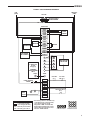
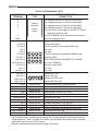
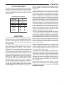
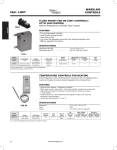
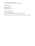
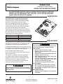
50A65-5165
Integrated Furnace Control
INSTALLATION INSTRUCTIONS
FAILURE TO READ AND FOLLOW ALL INSTRUCTIONS CAREFULLY BEFORE
INSTALLING OR OPERATING THIS CONTROL COULD CAUSE PERSONAL
INJURY AND/OR PROPERTY DAMAGE.
DESCRIPTION
The 50A65-5165 is an automatic gas interrupted
ignition control that employs a microprocessor to
continually monitor, analyze, and control the proper
operation of the gas burner, inducer, and fan.
Signals interpreted during continual surveillance of
the thermostat and flame sensing element initiate
automatic ignition of the burner, sensing of the flame,
and system shut-off during normal operation.
These controls incorporates system fault analysis for
quick gas flow shut-off, coupled with automatic ignition
retry upon sensing a fault correction. It is designed as a
replacement for the following controls:
Trane
White-Rodgers
CNT05164
CNT05165
50A65-475
50A65-476
50A65-5165
PRECAUTIONS
Installation should be done by a qualified heating and
air conditioning contractor or licensed electrician.
If in doubt about whether your wiring is millivolt, line, or
low voltage, have it inspected by a qualified heating and
air conditioning contractor or licensed electrician.
Do not exceed the specification ratings.
All wiring must conform to local and national electrical
codes and ordinances.
This control is a precision instrument, and should
be handled carefully. Rough handling or distorting
components could cause the control to malfunction.
Following installation or replacement, follow
manufacturer’s recommended installation/service
instructions to ensure proper operation.
! CAUTION
Do not short out terminals on gas valve or primary
control. Short or incorrect wiring may damage
the thermostat.
!
WARNING
Failure to comply with the following warnings could
result in personal injury or property damage.
FIRE HAZARD
• Do not exceed the specified voltage.
• Replace existing control with exact model and
dash number.
• Protect the control from direct contact with water
(dripping, spraying, rain, etc.).
• If the control has been in direct contact with
water, replace the control.
• Label all wires before disconnection when
servicing controls. Wiring errors can cause
improper and dangerous operation.
• Route and secure wiring away from flame.
SHOCK HAZARD
• Disconnect electric power before servicing.
• Ensure proper earth grounding of appliance.
• Ensure proper connection of line neutral and
line hot wires.
EXPLOSION HAZARD
• Shut off main gas to appliance until installation
is complete.
www.white-rodgers.com
www.emersonclimate.com
PART NO. 37-7516A
1409
SPECIFICATIONS
ELECTRICAL RATINGS [@ 77°F (25°C)]:
Input Voltage: 25 VAC 50/60 Hz
Max. Input Current @ 25 VAC: 0.45 amp
Relay Load Ratings:
Valve Relay: 1.5 amp @ 25 VAC 50/60 Hz 0.6 pf
Ignitor Relay: 2.0 amp @ 120 VAC 50/60 Hz
(resistive)
Flame Current Requirements:
Minimum current to insure flame detection: 1 µa DC*
Maximum current for non-detection: 0.1 µa DC*
Maximum allowable leakage resistance: 100 M ohms
*Measured with a DC microammeter in the flame probe lead
OPERATING TEMPERATURE RANGE:
-40° to 175°F (-40° to 80°C)
HUMIDITY RANGE:
5% to 93% relative humidity (non-condensing)
MOUNTING:
Surface mount multipoise
Timing Specs: (@ 60 Hz**)
maximum
Flame Establishing Time:
0.8 sec
Flame Failure Response Time:
2.0 sec
**At 50 Hz, all timing specifications should be increased
by 20%
Gases Approved: Natural, Manufactured, Mixed, Liquified
Petroleum, and LP Gas Air Mixtures are all approved for
use.
TIMING SPECIFICATIONS
(All times are in seconds, unless noted otherwise
Pre-Purge
Ignitor Warm-up
Trial for Ignition Period
Ignition Activation Period
Retries
Valve Sequence Period
Interpurge
Post-Purge
Lockout Time
Heat Delay-To-Fan-On
Heat Delay-To-Fan-Off*
Cool Delay-To-Fan-On
Cool Delay-To-Fan-Off*
Humidifier
Electronic Air Cleaner
Auto Reset Purge
50A65-5165
0
20
5
2
2 times
15
60
5
300
45
60/100/140/180
2
0/80
Yes
Yes
15
*These times will vary depending on option switch
position. The control is factory-set at 80 sec. cool
delay-to-fan-off and 180 sec. heat delay-to-fan-off.
See OPERATION section for further information.
INSTALLATION
MOUNTING AND WIRING
All wiring should be installed according to local and national
electrical codes and ordinances.
The control must be secured to an area that will experience
a minimum of vibration and remain below the maximum
ambient temperature rating of 175°F. The control is
approved for minimum ambient temperatures of -40°F.
Any orientation is acceptable.
Refer to the wiring diagram and wiring table when
connecting the 50A65 control to other components of
the system.
UL approved, 105°C rated 18 gauge, stranded, 2/64" thick
insulation wire is recommended for all low voltage safety
circuit connections. Refer to 50A65 specification sheet for
recommended terminals to mate with those on the control.
UL approved 105°C rated 16 gauge min., stranded, 4/64"
thick insulation wire is recommended for all line voltage
connections. Refer to 50A65 specification sheet for
recommended terminals to mate with those on the control.
The 50A65 has only one serviceable part–an automotive
type fuse, which protects the low voltage transformer
from damage if its output is short-circuited. If the fuse
has opened up, remove whatever caused the short circuit
and replace the fuse with only a 5 Amp automotive type
fuse. If the fuse is not the cause of the control’s problem,
replace the entire 50A65 control. There are no other user
serviceable parts.
2
! CAUTION
Do not short out terminals on gas valve or primary
control. Short or incorrect wiring may damage
the thermostat.
!
WARNING
FIRE HAZARD
• Do not exceed the specified voltage.
• Replace existing control with exact model and
dash number.
• Protect the control from direct contact with water
(dripping, spraying, rain, etc.).
• If the control has been in direct contact with water,
replace the control.
• Label all wires before disconnection when servicing controls.Wiring errors can cause improper and
dangerous operation.
• Route and secure wiring away from flame.
SHOCK HAZARD
• Disconnect electric power before servicing.
• Ensure proper earth grounding of appliance.
• Ensure proper connection of line neutral and line
hot wires.
EXPLOSION HAZARD
• Shut off main gas to appliance until installation is
complete.
WIRING
TYPICAL SYSTEM WIRING DIAGRAM
HOT
(LINE)
NEUTRAL
(LINE)
120 VAC
24 VAC CLASS II
TRANSFORMER
TH
24 VAC
TR
50A65-5165
COOL
HEAT
PARK
PARK
LINE
XFMR
EAC
HUM
INDUCER
HUMIDIFIER
IND
IGN
IND N
IGN N
CIRCULATOR
BLOWER
IGNITOR
CIR N
LINE N
XFMR N
HUM N
EAC N
ELECTRONIC
AIR CLEANER
50A65-475
or 50A65-476
in other
furnace(s)
—
TWINNING
APPLICATIONS
ONLY
TWIN*
Y
Y
W
W
G
G
R
R
C
COMPRESSOR
CONTACTOR
THERMOSTAT
TWIN*
HIGH LIMIT
(N. C.)
FLAME SENSOR
PROBE
GAS
VALVE
HLO
FP
TH
Not Used
Not Used
TR
HLI
GND
MV COM
PS
Not Used
MV
AUX. HIGH
LIMIT (N. C.)
PRESSURE SWITCH
(N. O.)
[12-Pin Connector]
LEGEND
Low Voltage (24 VAC)
Line Voltage (120 VAC)
N. C. = Normally closed switch
N. O. = Normally open switch
* The twinning feature is available only
onmodelswithsixscrewterminals;
one of these terminals will be
designated “TWIN”. All 50A65-475,
50A65-476 and 50A65-5165 controls
used in twinning applications must
have the “TWIN” terminal.
IND
IGN
IND
N
IGN
N
4-Pin Connector
HLO
PSO
HLI
FP
RO
OUT
GND
PS
RO
IN
TH
TR
MV
COM
MV
12-Pin Connector
3
WIRING
TYPICAL SYSTEM WIRING TABLE
50A65-5165
TERMINAL
TERMINAL
TYPE
W
G
R
Y
SYSTEM COMPONENT
CONNECTION
low voltage thermostat W terminal (or equivalent)
low voltage thermostat G terminal (or equivalent)
Terminal
block with
low voltage thermostat R terminal (or equivalent)
low voltage thermostat Y terminal (or equivalent)
(2nd wire from Y terminal goes to 24 VAC HOT side of
compressor contactor coil)
captive
screws
C
TWIN*
HLO (Pin 1)
FP (Pin 2)
TH (Pin 3)
(Pin 4)
(Pin 5)
TR (Pin 6)
HLI (Pin 7)
GND (Pin 8)
MV COM (Pin 9)
PS (Pin 10)
(Pin 11)
MV (Pin 12)
IND (Pin 1)
IGN (Pin 2)
IND-N (Pin 3)
IGN-N (Pin 4)
COOL
HEAT
PARK (2 terminals)
24 VAC COMMON side of compressor contactor coil
one wire twinning terminal
high limit OUTPUT
flame sensor probe†
HLO
HLI
FP
GND
TH
IND
TR
MV
COM
IGN
IND
N
PS
MV
IGN
N
24 VAC transformer (low voltage HIGH side)
not used
not used
24 VAC transformer (low voltage COMMON side)
high limit INPUT
MUST BE RELIABLY GROUNDED TO CHASSIS
gas valve COMMON
pressure switch INPUT
not used
gas valve
inducer HOT side
ignitor HOT side
inducer NEUTRAL side
ignitor NEUTRAL side
spade terminal
spade terminal
circulator blower COOL SPEED terminal
circulator blower HEAT SPEED terminal
spade terminal
spade terminal
unused circulator blower terminals
input voltage (120 VAC) HOT side
spade terminal
spade terminal
spade terminal
24 VAC transformer line voltage HOT side
humidifier HOT side
electronic air cleaner HOT side
LINE N
XFMR N
spade terminal
spade terminal
spade terminal
circulator blower NEUTRAL terminal
input voltage (120 VAC) NEUTRAL side
24 VAC transformer line voltage NEUTRAL side
HUM N (optional)
EAC N (optional)
spade terminal
spade terminal
humidifier NEUTRAL side
electronic air cleaner NEUTRAL side
LINE
XFMR
HUM (optional)
EAC (optional)
CIR N
* The twinning feature is available only on models with six screw terminals; one of these terminals
will be designated “TWIN”. All 50A65-475, 50A65-476 and 50A65-5165 controls used in twinning
applications must have the “TWIN” terminal.
† Maximum recommended flame probe wire length is 36 inches.
4
OPERATION
OPTION SWITCHES
The option switches on the 50A65-5165 control are used
to determine the length of the heat delay-to-fan-off periods
and cool delay-to-fan-off period. The following tables
shows the time periods that will result from the various
switch positions.
OPTION SWITCH POSITIONS
COOL delayto-fan-off:
Set switch
#1
0 sec.
80 sec.*
On
Off
HEAT delayto-fan-off:
Set switch
#2
#3
60 sec.
100 sec.
140 sec.
180 sec.*
On
On
Off
Off
Off
On
On
Off
*Factory setting
HEAT MODE
In a typical system, a call for heat is initiated by closing the
thermostat contacts.This starts the 50A65 control’s heating
sequence. The inducer blower and optional humidifier are
energized and the 768A silicon nitride ignitor is powered
within one second.
This control has an adaptive algorithm that reduces the
ignitor temperature to slightly greater than the minimum
temperature required to ignite gas in each particular
application. The control measures the line voltage and
determines an initial ignitor temperature setting based
on the measurement. After each successful ignition, the
control lowers the ignitor temperature slightly for the next
ignition attempt. The control continues to lower the ignitor
temperature until ignition does not occur, and the control
goes into retry mode. For the second attempt to ignite
gas within the same call for heat, the control increases
the ignitor temperature to the value it was on the fourth
previous successful ignition. After ignition is successful,
the control sets the ignition temperature at this value.
The 80 VAC Silicon Nitride ignitor manufactured
by White-Rodgers must be used. These ignitors are
specially designed to operate with the 50A65’s adaptive
ignition routine to ensure the most efficient ignitor
temperature.
At the end of the ignitor warm-up time, both valves in
the 36E manifold gas valve are opened. Flame must be
detected within 4 seconds. If flame is detected, the delayto-fan-on period begins. After the delay-to-fan-on period
ends, the circulator fan is energized at heat speed. If
there is an optional electronic air cleaner on the system,
the electronic air cleaner is also energized. When the
thermostat is satisfied, the gas valve is de-energized. After
proof of flame loss, the delay-to-fan-off period begins and
the inducer blower remains energized to purge the system
for 5 seconds. When the purge is complete, the inducer
blower and humidifier are de-energized. After the delayto-fan-off period ends, the circulator fan and electronic air
cleaner are de-energized. If flame is not detected, both
valves are de-energized, the ignitor is turned off, and the
50A65 control goes into the “retry” sequence.
The “retry” sequence provides a 60-second wait following
an unsuccessful ignition attempt (flame not detected).
After this wait, the ignition sequence is restarted again.
If this ignition attempt is unsuccessful, one more retry
will be made before the control goes into system lockout.
If flame is detected, then lost, the 50A65 control will repeat
the initial ignition sequence for a total of ten “recycles”.
After ten unsuccessful “recycle” attempts, the control will
go into system lockout.
If flame is established for more than 10 seconds after
ignition, the 50A65 controller will clear the ignition attempt
(or retry) counter. If flame is lost after 10 seconds, it will
restart the ignition sequence. This can occur a maximum
of 11 times before system lockout.
A momentary loss of gas supply, flame blowout, or a
shorted or open condition in the flame probe circuit will be
sensed within 2.0 seconds. The gas valve will de-energize
and the control will restart the ignition sequence. A recycle
will begin and the burner will operate normally if the gas
supply returns, or the fault condition is corrected, before
the last ignition attempt. Otherwise, the control will go
into system lockout.
If the control has gone into system lockout, it may be
possible to reset the control by a momentary power
interruption of ten seconds or longer. Refer to SYSTEM
LOCKOUT FEATURES.
5
OPERATION
COOL MODE
In a typical system, a call for cool is initiated by closing the
thermostat contacts.This energizes the 50A65 control and
the compressor. The cool delay-to-fan-on period begins.
After the delay period ends, the optional electronic air
cleaner is energized, and the circulator fan is energized
at cool speed. After the thermostat is satisfied, the
compressor is de-energized and the (optional) cool mode
delay-to-fan-off period begins. After the optional delay-tofan-off period ends, the circulator fan and electronic air
cleaner (optional) are de-energized.
MANUAL FAN ON MODE
If the thermostat fan switch is moved to the ON position,
the circulator fan (heat speed) and optional electronic air
cleaner are energized. When the fan switch is returned
to the AUTO position, the circulator fan and electronic air
cleaner (optional) are de-energized.
TWINNING INTERFACE
If the control has six screw terminals, one of which is
designated TWIN, the control is equipped with a single
wire twinning interface. If twinning is used, either control
will process a call for heat, cool or fan as described above.
However, after the heat-, cool-, or fan-on delay time
expires, both units will energize the circulator blowers at
the same time. Likewise, after the heat-, cool-, or fan-off
delay time expires, both units will de-energize the circulator
blowers at the same time. This allows for proper air flow
to be obtained. To assure proper control operation, both
controls must share a common transformer ground (TR).
To enable twinning, do the following:
1. Power supplied to both furnaces must be from the
same phase of the incoming 120 VAC power.
2. Connect the TWIN screw terminals on the 50A65475, 50A65-476 or 50A65-5165 of the furnaces to
be twinned to each other using a single wire (14-22 AWG).
6
SYSTEM LOCKOUT AND
DIAGNOSTIC FEATURES
SYSTEM LOCKOUT FEATURES
When system lockout occurs, the gas valve is de-energized,
the circulator blower is energized at heat speed, and, if
flame is sensed, the inducer blower is energized. The
diagnostic indicator light will flash or glow continuously
to indicate system status. (System lockout will never
override any precautionary features.)
To reset the control after system lockout, do one of
the following:
1. Interrupt the call for heat or cool at the thermostat for
at least one second but less than 20 seconds (if flame
is sensed with the gas valve de-energized, interrupting
the call for heat at the thermostat will not reset the
control).
2. Interrupt the 24 VAC power at the control for at least
ten seconds. You may also need to reset the flame
rollout sensor switch.
3. After one hour in lockout, the control will automatically
reset itself.
DIAGNOSTIC FEATURES
The 50A65-5165 control continuously monitors its own
operation and the operation of the system. The LED light
on the control will flash slowly (one flash per second)
if there are no failures and no call for heat. If there is
a call for heat, the LED will flash quickly (one flash per
half-second). If a failure occurs, the LED will indicate a
failure code as shown in Troubleshooting section. If the
failure is internal to the control, the light will stay on
continuously. In this case, the entire control should
be replaced, as the control is not field-repairable. If
the LED is continuously off, there may be no power to
the control; the fuse on the control may be open; or there
may be a failure in the control.
If the sensed failure is in the system (external to the
control), the LED will flash in the following flash-pause
sequences to indicate failure status (each flash will last
approximately 0.25 seconds, and each pause will last
approximately 2 seconds).
OPERATION
DEFINITION OF TERMS
Auto Restart – After one (1) hour of internal or external
lockout, the control will automatically reset itself and go
into an auto restart purge for 60 seconds.
Cool Delay-To-Fan-Off – The period of time between the
loss of a call for cool and the deactivation of the blower
motor at Cool speed.
Cool Delay-To-Fan-On – The period of time after a thermostat
demand for cool before energizing the circulator blower
motor at Cool speed.
Flame Failure Response Time (FFRT) – The period of time
between loss of the supervised main burner flame and
the action to shut off the gas supply.
Heat Delay-To-Fan-Off – The period of time between the
loss of a call for heat and the deactivation of the blower
motor at Heat speed.
Heat Delay-To-Fan-On – The period of time between proof
of the supervised main burner flame and the activation of
the blower motor at Heat speed.
Igniter Warm-up Time – The length of time allowed for the
igniter to heat up prior to the initiation of gas flow.
Ignition Activation Period (IAP) – The period of time
between energizing the main gas valve and deactivation
of the ignition means prior to the end of TFI.
Inter-purge – The period of time intended to allow for the
dissipation of any unburned gas or residual products of
combustion between the failed trial for ignition and the
retry period.
Post-purge Time – The period of time intended to allow for
the dissipation of any unburned gas or residual products
of combustion at the end of a furnace burner operating
cycle. Post-purge begins at the loss of flame sense.
Pre-purge Time – The period of time intended to allow for the
dissipation of any unburned gas or residual products of
combustion at the beginning of a furnace operating cycle
prior to initiating ignition.
Recycles – The additional attempts within the same
thermostat cycle for ignition after loss of the supervised
ignition source or the supervised main burner flame.
Retries – The additional attempts within the same thermostat
cycle for ignition when the supervised main burner flame
is not proven within the first trial for ignition period.
Trial for Ignition Period (TFI) – The period of time between
initiation of gas flow and the action to shut off the gas flow
in the event of failure to establish proof of the supervised
ignition source or the supervised main burner flame.
7
TROUBLESHOOTING
Red LED
Flash
Error/Condition
Comments/Troubleshooting
Slow Flash
Normal operation
Normal – no Call for Heat
Fast Flash
Normal operation
Normal – Call for Heat
2
External lockout (exceeded retries)
Failure to sense flame is often caused by carbon deposits on
the flame sensor, a disconnected or shorted flame sensor lead
or a poorly grounded furnace. Carbon deposits can be cleaned
with emery cloth. Verify sensor is not contacting the burner
and is located in a good position to sense flame. Check sensor
lead for shorting and verify furnace is grounded properly. Verify
gas supply to valve, gas valve in "On" position and appliance
lighting properly. Verify flame reaches flame sensor during
ignition attempts and gas pressures are correct.
3
Pressure switch problem, vent on Inducer
problem
Check switch function, verify inducer is working correctly. Refer
to wiring diagram, terminals PS.
4
Open high temperature limit switch
Verify continuity through limit switch circuit. Refer to wiring
diagram terminals, HLO.
5
Flame sensed with gas valve de-energized
Verify the gas valve is operating and shutting down properly.
Flame in burner assembly should extinguish promptly at the
end of the cycle. Check orifices and gas pressure.
6
Reversed polarity
Verify the control and furnace are properly grounded. Check
and reverse polarity (primary or secondary) if incorrect.
7
Gas valve circuit error
Indicates the gas valve relay contacts on the ignition module is
not functioning properly. Replace the ignition module.
8
Low flame sense current
Low flame sense current is often caused by carbon deposits on
the flame sensor, a poorly grounded furnace or a mis-aligned
flame sense probe. Carbon deposits can be cleaned with
emery cloth. Check or improve furnace and module ground.
Verify sensor is located in or very near flame as specified
by the appliance manufacturer. Refer to wiring diagram FS
terminal and GND.
9
Ignition fault
Check ignitor or improper grounding
Continuous
On
Control failure
Replace IFC
Off
Control failure
Verify power to the control
TECHNICAL SUPPORT: 1-888-725-9797
White-Rodgers is a business
of Emerson Electric Co.
The Emerson logo is a
trademark and service mark
of Emerson Electric Co.
www.white-rodgers.com
www.emersonclimate.com