1
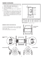
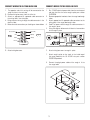
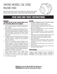
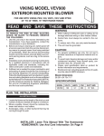
VIKING MODEL VIL1200
INLINE FAN
ONLY FOR USE WITH: VWH, VIH, VBCV, VICV, DTWL AND
DTWN 24"W TO 66"W WALL AND ISLAND HOODS
READ AND SAVE THESE INSTRUCTIONS
WARNING
CAUTION
1. For general ventilating use only. Do not use to exhaust
hazardous or explosive material and vapors.
2. To avoid motor bearing damage and noisy and/or
unbalanced impellers, keep drywall spray, construction
dust, etc. off power unit.
3. Please read specification label on product for additional
information and requirements.
4. Unit has an unguarded impeller. Do not use in locations where
the impeller is readily accessible to people or animals.
5. Screen guards must be installed if impeller is within reach
of personnel, and less than 7 feet above the floor.
6. When handling fan wear hand protection and stay
clear of sharp edges.
7. Because this unit has rotating parts, safety should be
exercised during all phases of installation, operation and
maintenance.
8. The motor is permanently lubricated. Do not oil or disassemble motor.
9. Electrical circuit, including speed control, (if used), must
be rated 5.0 AMPS minimum.
TO REDUCE THE RISK OF FIRE, ELECTRIC SHOCK, OR INJURY TO PERSONS, OBSERVE THE FOLLOWING:
1. Use this unit only in the manner intended by the manufacturer. If you have questions, contact the manufacturer or
your distributor.
2. Before servicing or cleaning unit, switch power off at service panel and lock the service disconnecting means to prevent power from being switched on accidentally. When the
service disconnecting means cannot be locked, securely
fasten a prominent warning device, such as a tag, to the
service panel.
3. Installation work and electrical wiring must be done by
a qualified person(s) in accordance with all applicable
codes and standards, including fire rated construction
codes and standards.
4. Sufficient air is needed for proper combustion and exhausting of gases through the flue (chimney) of fuel
burning equipment to prevent backdrafting. Follow the
heating equipment manufacturer’s guidelines and safety
standards such as those published by the National Fire
Protection Association (NFPA), and the American Society
for Heating, Refrigeration and Air Conditioning Engineers
(ASHRAE), and the local code authorities.
5 When cutting or drilling into wall, or ceiling, do not
damage electrical wiring or other hidden utilities.
6. Ducted fans must always be vented to the outdoors.
7. To reduce risk of fire, use only metal ductwork.
8. This unit must be grounded.
SPECIFICATIONS
MODEL
VOLTS
AMPS
CFM
DUCT SIZE
VIL1200
115
4.84
1200
10” DIA.
INSTALLER: Leave this Manual With The Homeowner
HOMEOWNER: Use And Care Information On Page 4
1
PLANNING THE INSTALLATION
1. Locate the inline fan so that the length of the duct run and
number of elbows needed is kept to a minimum.
2. The inline fan is designed for use with 10” diameter duct.
3. Use rigid metal ductwork.
4. Always install ventilation products with an approved wall
or roof cap.
5. For a truly quiet kitchen ventilation system add a Viking
Inline Duct Silencer part number VSIL10 (sold separately)
to the installation. The simple addition of a inline duct silencer between the range hood and the VIL1200 fan can
typically reduce the perceived sound level of the system
by more than 50%.
�
����
�
�
MODEL
A
B
C
D
E
Weight
VIL1200
†10
1
14
15
8
21 lbs.
All dimensions in inches.
† Duct connections are ¹⁄₈
¹ smaller than the duct size.
MOUNTING THE VIL1200 INLINE FAN
Vertical Installation
with out Kit
To minimize any potential vibration noise it is recommended
that the inline fan be mounted with Viking Vibration Isolation
Kit part number ILVK (sold separately).
Various mounting methods are shown below.
Vertical Installation
with Kit
Horizontal Installation
with Kit
Horizontal Installation
with out Kit
2
CONNECT WIRING TO VIL1200 INLINE FAN
CONNECT WIRING TO THE ROUGH-IN PLATE
1. The opposite end of this wiring will be connected to the
rough-in plate in the next step.
2. Remove wiring box cover from the inline fan.
3. Attach an appropriate UL approved cable connector to
the wiring hole in the wiring box.
4. Bring electrical wiring through the cable connector in the
electrical box.
5. Make electrical connections per the diagram shown below
1.
2.
3.
4.
5.
��������
������������
�����
�����
����
���������
�����
���������
Run 115VAC electrical power cable from the service panel
and from the inline fan to the rough-in plate part number
PV300008.
Remove appropriate knockouts from the range hood rough
in box.
Attach appropriate UL approved cable connectors to the
wiring holes in the range hood rough-in box.
Feed 6” of power cable through the cable connectors in
the rough-in plate.
Using the diagram below make all electrical connections
to the rough-in plate.
115V
������
�
�������
�����
���������
6. Attach wiring box cover.
6.
Attach wiring box cover to rough-in plate.
7.
Attach rough-in plate to the studs at the inside top of
the range hood with the (4) #10-24 nuts part number
PV300146 provided.
8.
Connect the plugin power cables of the rough-in kit to
the range hood.
3
CONNECTING DUCT WORK TO VIL1200 INLINE FAN
USE AND CARE
Two duct clamps part number 001377-000 are included
with this unit and are intended to simplify fan installation
and isolate fan vibration from the rigid metal duct.
Disconnect electrical power supply and lock out service panel
before cleaning or servicing this unit.
Note: The duct clamps are
convenient in installations
where regular removal of the
fan in necessary for inspection and cleaning.
CLEANING
Periodic inspection and cleaning is recommended. The frequency of inspection and cleaning should be adjusted according to the type and amount of cooking.
8mm
neoprene pad
The interior of the fan can to accessed by removing the duct
clamp and gently moving the duct work away from the inlet
of the fan.
The built in hanger tab of the duct clamps are not intended to
support the weight of the inline fan. The inline fan should be
supported with the integral brackets of the inline fans.
If excess build up is present it should be removed from the
interior of the fan and from the impeller of the fan.
If special supports are required in anticipation of earthquakes
the duct clamps that are supplied with the VIL1200 are not
intended to meet these requirements.
MOTOR LUBRICATION
To minimize vibration, leave a 1/4” gap between the inline fan
collars and rigid duct.
The motor is permanently lubricated. Do not oil or disassemble motor.
Tighten the two screws until the fan and duct are snugly attached.
The duct work at the inlet of the inline fan is to be connected
to the rough-in plate.
The duct work at the out box of the inline fan is to be connected to a roof or wall cap.
A inline butterfly damper part number PV300006 is included
with the VIL1200. The damper can be installed anywhere
in the duct system. Damper must be installed so that the
airflow direction will open the butterfly blades. Mounting the
damper in an inverted position may prevent the blades from
closing completely. The preferred installation position is vertical as shown below.
Damper
Airflow
Direction
RSK
Damper
Duct
Collar
VIKING RANGE CORPORATION
GREENWOOD, MISSISSIPPI 38930 USA
ROUGH-IN
PLATE
4
Item #:450355
Date: 060707