1
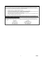
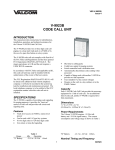
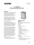
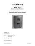
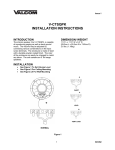
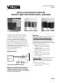
VSP-V-1016,V-1022C-27C
Issue 4
INSTALLATION INSTRUCTIONS FOR
ONE-WAY AMPLIFIED INTERIOR WALL SPEAKERS
V-1022C, V-1024C, V-1026C
V-1016-B, V-1016-W
Valcom One-Way Amplified Interior Speakers,
V-1016-W, V-1016-BK, V-1022C, V-1023C,
V-1024C, V-1025C, V-1026C, V-1026C-W,
V-1027C, are self-amplified and capable of
reproducing paging as well as background music.
These speakers have externally accessible volume
controls that are screwdriver adjustable. The
enclosures are vinyl laminated pressboard with either
a coordinating cloth or woven can grille. All
speakers require -24 Vdc, 50 mA (1 power unit) and
are FCC Part 68 registered under
BAFUSA-69358-KX-N.
Mounting
Ideal mounting heights are 8 to 12 ft. above the floor.
V-1016-BK, V-1016-W, V-1022C, V-1023C:
Remove the screw holding the mounting bracket to
the speaker housing. Mount bracket using appropriate hardware such as #8 pan head screws. After
making the required connections, reattach the speaker
housing to the mounting bracket.
• V-1016 – 9.7”H x 11.5”W x 4.0”D
(24.6cm H x 29.2cm W x 10.16cm D)
• 4.1 lbs. (1.86kg)
• V-1022C – 9.6”H x 11.5”W x 4.2”D
(24.4cm H x 29.2cm W x 10.7cm D)
• 4.5 lbs. (2.04kg)
• V-1023C – 9.6”H x 11.5”W x 4.2”D
(24.4cm H x 29.2cm W x 10.7cm D)
• 4.1 lbs. (1.86kg)
INSTALLATION
(Tip/A)
Page
Out
(Ring/B)
(-24Vdc)
(Gnd)
V-1023C, V-1025C, V-1027C
One-Way
Amplified
Speaker
V-1024C, V-1025C: After making required connections, use appropriate hardware such as an 8d
finishing nail to hang the speaker housing in the
corner.
• 10.5”H x 9.5”W x 6.3”D
(26.7cm H x 24.1cm W x 16cm D)
• 3.6 lbs. (1.63kg)
Valcom Page
Control
Valcom -24 Vdc
Power Supply
Typical Connections
NOTE: Do not connect this speaker directly to a
25/70/100 volt amplifier as damage to both the
amplifier and speaker may occur. A V-1095 may
be used to allow the use of Valcom self-amplified
speakers on 70V speaker lines.
1
947296
V-1026C, V-1026C-W, V-1027C: Remove wing
nuts holding mounting bracket to speaker housing.
Remove bracket and mount using appropriate
hardware such as #8 pan head screws. Reattach
speaker housing to mounting bracket. Remove the 4
screws holding the reverse side grille to the speaker
housing and remove the grille. After making required
connections, reattach the grille to the speaker
housing.
• 10.3”H x 10.3”W x 4.2”D
(26.2cm H x 26.2cm W x 10.7cm D)
• 5.6 lbs. (2.54kg)
COVERAGE
The area covered by a wall speaker is typically 600
square feet.
22 AWG
24 AWG
400
800
1600
100
50
25
60
30
15
1 Watt Interior
Speakers
30
15
7
22 AWG
200 ft.
400 ft.
800 ft.
24 AWG
125 ft.
250 ft.
500 ft.
TECHNICAL ASSISTANCE
When trouble is reported, verify there are no broken
connections. Assistance in troubleshooting is
available from the factory. Call (540) 427-3900 and
ask for Technical Support, or call (540) 427-6000 for
Valcom 24-hour Automated Support or visit our
website at http://www.valcom.com.
Valcom equipment is not field repairable. Valcom,
Inc. maintains service facilities in Roanoke, VA.
Should repairs be necessary, attach a tag to the unit
clearly stating company name, address, phone
number, contact person, and nature of the problem.
Send the unit to:
Valcom, Inc.
Repair & Return Dept.
5614 Hollins Road
Roanoke, VA 24019-5056
Number of Speakers per Audio Run
Wire Run (Ft.)
Number of Speakers per Power Run
TROUBLESHOOTING CHART
1.
SYMPTOM
No audio from
speaker.
1a.
1b.
2.
Low volume from
speaker.
2a.
2b.
2c.
3.
Loud squeal
(feedback).
3a.
3b.
3c.
3d.
ACTION
Check that volume control is turned up (clockwise).
Using a lineman's test set check for the proper audio level on the Tip and Ring
leads, and if necessary also at the source.
Check that volume control is turned up.
Check voltage at the speaker assembly when in use, -18 to -24 Vdc required.
Using a lineman's test set, check for the proper audio level on Tip and Ring
leads. It is possible that some low level audio will be heard with only one side of
Tip and Ring connected.
Turn down (counter-clockwise) volume of the speaker.
Increase the distance between the telephone and speaker.
Install a noise canceling handset on the telephone in severe problem areas.
Add a V-9962 Digital Feedback Eliminator.
2
947296
VALCOM LIMITED WARRANTY
Valcom, Inc. warrants its products to be free from defects in materials and workmanship under conditions of normal use and
service for a period of one year from the date of shipment. The obligation under this warranty shall be limited to the replacement,
repair or refund of any such defective device within the warranty period, provided that:
1.
2.
3.
4.
5.
inspection by Valcom, Inc. indicates the validity of the claim,
the defect is not the result of damage, misuse, or negligence after the original shipment.
the product has not been altered in any way or repaired by others and that factory sealed units are unopened (A service
charge plus parts and labor will be applied to units defaced or physically damaged),
freight charges for the return of products to Valcom are prepaid,
all units ‘out of warranty’ are subject to a service charge. The service charge will cover minor repairs (Major repairs will
be subject to additional charges for parts and labor).
This warranty is in lieu of and excludes all other warranties, expressed or implied, and in no event shall Valcom, Inc. be
liable for any anticipated profits, consequential damages, loss of time or other losses incurred by the buyer in connection
with the purchase, operation, or use of the product.
This warranty specifically excludes damage incurred in shipment. In the event a product is received in damaged condition, the
carrier should be notified immediately. Claims for such damage should be filed with the carrier involved in accordance with the
F.O.B. point.
Headquarters:
In Canada
Valcom, Inc.
CMX Corporation
1111 Industry Avenue
35 Van Kirk Drive #11 and 12
Roanoke, VA 24013
Brampton, Ontario L7A1A5
Phone: (540) 427-3900
Phone: (905) 456-1072
FAX: (540) 427-3517
FAX: (905) 456-2269
3
947296